
...
| Информация |
|---|
Initial data Integration of the ECSS-10 Class 5 software switch (SSW) on 1 physical server with support for SIP with the following parameters per load:
|
According to the technical specification, it is required to determine the hardware platform.
Table 1. Recommended hardware solutions
Example of drafting hardware requirements
Device | Required resource | |
|---|---|---|
Hardware product series | ||
|---|---|---|
Light+
Midi
Heavy
Super Heavy
System specifications
Maximum number of subscribers
5000
10000
20000
40000
Maximum load of simultaneous connections class 5
800
1500
3000
6000
Maximum load of simultaneous connections class 4
2400
4500
9000
20000
Server specifications
Model
HP (Lenovo)
HP (Lenovo)
HP (Lenovo)
HP (Lenovo)
Series
DL20 Gen10 (SR250)/DL 360 Gen10 (SR530)
DL360 Gen10 (SR530/SR630)
DL360 Gen10 (SR630)
DL 360 Gen10 (SR630)
Processor
Intel Xeon E-2276G/Intel Xeon 4214
Intel Xeon 5220
Intel Xeon 6240
Intel Xeon 8268
Number of processors
1
1
2
2
RAM
12 GB
16 GB
24 GB
64 GB
HDD
(from 7200 rpm)
from 3X500 SATA
(from 7200 rpm)
from 3x300 GB SAS (from 10000 rpm)
from 3x600 GB SAS
(from 10000 rpm) 2x150GB SSD
from 6x800 GB SSD, 2x300 GB M.2 SSD
RAID
no raid board
HW Raid, from 1 GB cache+battery
HW Raid, from 1 GB cache+battery
HW Raid, from 2GB Flash cache, RAID-5
Remote management license
optional
+
+
+
Redundant power supply
optional
+
+
+
Conversation records storage
additional HDD combined to RAID-5
HW Raid license with RAID-5 support, additional HDD for storing records
HW Raid license with RAID-5 support, additional HDD for storing records
Table 2. Example of drafting hardware requirements
...
Device
...
Required resource
...
Hardware product series
...
MCL
...
MUL
...
Server 1
...
2000
...
15000
...
Heavy
...
After determining the requirements of the project, create a preliminary network map.
Table 3. An example of components allocation in the address space for a single node
...
Server name (host)
...
Role
...
Interface
...
Address
...
Port
...
Static addresses of the software switch
...
ecss1
...
Core addres (ecss-core)
...
net.20
...
10.0.20.11/24
...
5000
...
ecss2
...
Core addres (ecss-core)
...
net.20
...
10.0.20.12/24
...
5000
...
Internal addresses of the software switch
...
Connecting to network
The topology of connecting the server to the network to ensure redundancy is recommended to be done using 2 switches.
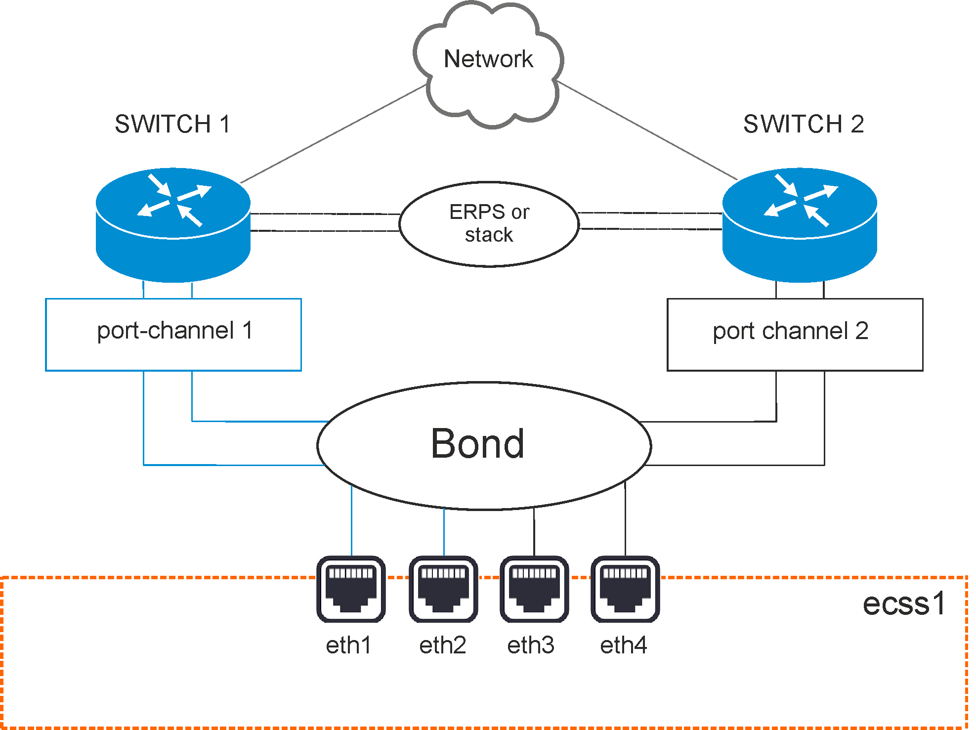
Figure 1 — Network connection diagram
Option 1. Active-backup
The switches are connected in erps ring.
All 4 physical network interfaces are connected into 1 aggregated link (bond). Server port aggregation is configured in active-backup mode, i.e. there is always only 1 network interface in operation. Server network interfaces are included in pairs in switches, on which port aggregation (port-channel) is also configured in active-backup mode. For example, eth0 and eth1 are included in the first switch, and eth2 and eth3 are included in the second.
Option 2. LACP
The switches are connected in stack. The stack must logically operate as a single switch, capable of providing port aggregation between different physical switches in LACP mode. MES-3124 with specialized firmware can be an example.
All 4 physical network interfaces are connected into 1 aggregated link (bond). Server port aggregation is configured in 802.3ad mode. Network cards aggregated groups with same rate and duplex are created. With such a combination, the transmission uses all channels in active aggregation according to the IEEE802.3ad standard. The choice on which interface to send a packet is determined by policy. By default, it is XOR policy, also xmit_hash policy can be used. For more information, see Netplan section.
Requirements:
- Ethtool support in driver to obtain information about speed and duplex on each network interface;
- IEEE802.3ad standard support on switch.
...
MCL | MUL | ||
|---|---|---|---|
Server 1 | 2500 | 15000 | Heavy |
After determining the requirements of the project, create a preliminary network map.
An example of components allocation in the address space for a single node:
Server name (host) | Role | Interface | Address | Port |
|---|---|---|---|---|
Static addresses of the software switch | ||||
| ecss1 | Server address | net.10 (mgm) | 10.0.10.10/24 | - |
| ecss2 | Protocole adapter address | net.20 (voip) | 10.0.20.10/24 | - |
ecss1 | Gateway address | net.10 (mgm) | 10.0.10.1 | - |
ecss2 | DNS server addresses | net.10 (mgm) | 10.0.10.1, 8.8.8.8 | - |
Internal addresses of the software switch | ||||
| ecss1 | Core address (ecss-core) | lo | 127.0.0.1/24 | 5000 |
| ecss2 | Media server address (ecss-media-server (MSR)) | lo | 127.0.0.1/24 | 5040 |
Connecting to network
The topology of connecting the server to the network to ensure redundancy is recommended to be done using 2 switches.
draw.io Diagram border true diagramName stack simpleViewer false width 600 links auto tbstyle top lbox true diagramWidth 1966 revision 1
Figure 1 — Network connection diagram
Option 1. Active-backup
The switches are connected in erps ring.
All 4 physical network interfaces are connected into 1 aggregated link (bond). Server port aggregation is configured in active-backup mode, i.e. there is always only 1 network interface in operation. Server network interfaces are connected in pairs in switches, on which port aggregation (port-channel) is also configured in active-backup mode.
For example, eth0 and eth1 are connected in the first switch, and eth2 and eth3 are connected in the second.
Option 2. LACP
The switches are connected in a stack. The stack must logically operate as a single switch, capable of providing port aggregation between different physical switches in LACP mode. MES-3124 with specialized firmware can be an example.
All 4 physical network interfaces are connected into 1 aggregated link (bond). Server port aggregation is configured in 802.3ad mode. Network cards aggregated groups with same rate and duplex are created. With such a combination, the transmission uses all channels in active aggregation according to the IEEE 802.3ad standard. The choice on which interface to send a packet is determined by policy. By default, it is XOR policy, also xmit_hash policy can be used. For more information, see Netplan section.
Requirements:
- Ethtool support in driver to obtain information about speed and duplex on each network interface;
- IEEE802.3ad standard support on switch.
Server network interfaces are also included in pairs in switches, on which port aggregation (port-channel) is configured in LACP mode. For example, eth0 and eth1 are included to first switch (port-channel 1), and eth2 and eth3 — to the second (port-channel 2).
Installation of ECSS-10 on one server
Installation of ECSS-10 consists of two main parts:
- Preparation: installation of Ubuntu 22.04, Ubuntu packets updating, OS "optimization", installation of additional software packages, preparation of network interfaces, /etc/hosts, ssh-keygen
- Installation of ECSS-10
Preparation
This section describes the operating system installation, as well as required and optional packages. ECSS-10 version 3.18 runs on Ubuntu 22.04.
Preliminary requirements:
- Installation media with the operating system distribution;
- A prepared server with an updated BIOS, ILP (if available), and a connected network for internet access;
- Setting the installation media (USB flash drive or CD/DVD) as the first boot priority in the BIOS;
- Sufficient disk space and memory as specified in the design.
| Якорь | ||||
|---|---|---|---|---|
|
To install the OS, do the following:
- After booting from the installation media, select "Install Ubuntu Server"
- Select the system language and keyboard layout
- Configure the network interface to connect to the Internet
- Create disk partitions according to Table 1
- Configure server and user names
- Install OpenSSH server
- Reboot the successfully installed OS
| Раскрыть | ||||||
|---|---|---|---|---|---|---|
| ||||||
|
Table1 — An option for storing information in a file system on physical media for servers
| 1 | Operating system boot partition (created automatically) | boot | raid 1: hdd1, hdd2 | boot | /boot | ext4 | 1 GB | Primary |
| 2 | Operating system root partition | root | raid 1: hdd1, hdd2 | root | / | ext4 | 30 GB | Logical |
| 3 | Local database information | mnesia | raid 1: hdd1, hdd2 | mnesia | /var/lib/ecss | ext4 | 10 GB | Logical |
| 4 | Distributed database for storing media resources | glusterfs | raid 1: hdd1, hdd2 или hdd3 | glusterfs | /var/lib/ecss/glusterfs* | ext4 | Max GB | Logical |
| 5 | OS subsystem operation logs | log | raid 1: hdd1, hdd2 или hdd3 | log | /var/log | ext4 | 20 GB | Logical |
| 6 | ECSS subsystem operation logs | ecss_log | raid 1: hdd1, hdd2 или hdd3 | ecss_log | /var/log/ecss | ext4 | 20 GB | Logical |
| 7 | Databases | ecss_db | raid 1: hdd1, hdd2 или hdd3 | ecss_db | /srv/ecss/ecss-postgres-bdr-ssw/ | ext4 | 100–400 GB** | Logical |
| 8 | User files | home | raid 1: hdd1, hdd2 или hdd3 | home | /home | ext4 | 10 GB | Logical |
| Примечание |
|---|
* If the server will not work in a cluster, then a partition /var/lib/ecss/restfs is created instead of glusterfs. ** The recommended value for series Light, Light+, Midi is 100 GB. The recommended value for series Heavy is 200 GB, for Super Heavy is 400 GB. |
The system requires at least 256 GB of free space.
It is neccessary to configure "hostname" parameter on the system servers.
It is recommended to specify the same username (anything except ssw) on all servers in the system. The ECSS-10 license is linked to the eToken/ruToken key and the computer hostname. The system user ssw is created when installing the ecss-user package.
| Подсказка |
|---|
When installing the system in a cluster, the recommended value for the first server is ecss1, for the second – ecss2. |
Configuring network
Install the software switch according to the parameters specified in the technical specification. In this example, it is assumed that the required operating system is already installed.
...