|| DeviceType | IP camera |
|| DeviceName1 | SV-BB341Z-E2B |
|| DocTitleAdditional | User manual |
|| fwversion | 1.2.0 | |
|
Notes and warnings
Notes contain additional information on using and configuring the device. |
Tips contain important information, tips or recommendations on device operation and setup. |
Product description
SV-BB341Z-E2B is a camera designed for real-time video surveillance. Due to the FullHD resolution, the transmitted image is clear and detailed. A varifocal lens makes it possible to adjust the field of view to suit a specific location and to change the magnification during observation to examine important objects in detail without losing image quality. PoE technology allows installing the camera everywhere, regardless of the location of the power supply. It also saves on the cost of power cables and makes the installation simple and not time-consuming.
Features and capabilities:
– Night vision provides clear images even in low-light conditions.
– Motion detection notifies you of events as they occur.
– Video archive provides options for saving recordings: to a memory card for local storage or to network storage1. If the local storage fails, all recordings will remain available on the network storage.
– PoE power supply.
1 Support for the function of saving records to network storage is under development. |
Technical specifications
| Interfaces |
|---|
| Ethernet | 1 × 10/100BASE-T (RJ-45), support for PoE |
| Memory card | 1 × MicroSD/SDHC/SDXC up to 512 GB |
| Network |
|---|
| Protocols | TCP/IP, UDP, ICMP, HTTP, HTTPS, SSL/TLS, QoS, DHCP, DNS, RTP, RTSP, RTMP, NTP, SMB, NFS, TFTP |
| API | ONVIF (Profile S, Profile T), WSS API |
| Security | password protection, complex password, HTTPS encryption, WS-Username token, WS-Username basic for ONVIF, TLS1.3 |
| User/host | up to 10 users, 2 user levels: administrator, operator |
| Operating system |
|---|
| Linux SDK |
| Sensor |
|---|
| Type | 1/1,8” progressive scan CMOS |
| Effective pixels | 2 MP |
| Lens and illumination |
|---|
| Focal distance | 2.7–13.5 mm |
| Optical zoom | 4х |
| Aperture | F/1.6–3.3 |
| Field of view (horizontal) | 108–30° |
| Field of view (diagonal) | 131–35° |
| Field of view (vertical) | 56–17° |
| Angle adjustment (tilt) | from 0° to 90° |
| Angle adjustment (rotate) | from 0° to 360° |
| IR illumination | yes |
| IR range | up to 80 m |
| Image |
|---|
| Image | color |
| Maximum resolution | 2688×1520 |
| Maximum frame rate | main stream: 5–50 frames per second (without WDR),
5–25 frames per second (with WDR);
resolution: 1920×1080, 1280×720
sub stream: 5–25 frames per second;
resolution: 1920×1080, 1280×720, 960×540, 640×360
additional stream: 5–25 frames per second;
resolution: 960×540, 640×360, 480×270, 320×180 |
| Bit rate | up tp 10 Mbps |
| Video compression | H.264, H.265 |
| Image quality improvement | DNR 2D/3D, WDR (from 100 dB), BLC, AE, AWB, HLC, ANTI-FLICKER, DEFOG |
| Signal-to-noise ratio | no less than 50 dB |
| ISO | color: 0.005 lx;
bw: 0 lx with IR |
| Audio |
|---|
| Built-in microphone | yes |
| Audio input/output | 1 input/1 output |
| Alarm interface | 1 input/1 output (12 V, 0.3 A) |
| Audio compression | PCM, G.711A (PCMA), G.711U (PCMU), AAC, MP2, MP3 |
| Voice pickup distance | syllable intelligibility: up to 5 meters for the built-in microphone up to 10 meters for an external microphone |
| Physical specifications |
|---|
| Power supply | 12 V DC, PoE 802.3at, Class 4, max. 15 W |
| RAM | 256 MB |
| ROM | 128 MB |
| Casing | metal |
| Form factor | cylindrical camera |
| Mount options | indoor and outdoor |
| Dimensions (W × H × D) | 90 × 85 х 250 mm |
| Weight | 0.78 kg |
| Operating temperature | from -40 to +60° |
| Operating humidity | no more than 90 % (non-condensing) |
| Ingress protection | IP67 |
| Lightning protection | TVS 6000 V (protection against impulse and transient overvoltages)1 |
| Lifetime | no less than 5 years |
1 The protection works only if the device is properly connected to a protective earth (PE). Failure to follow the installation instructions and lack of
grounding significantly reduce the effectiveness of the protection and may cause the device to fail during a lightning strike. |

Design
Front view
The front view of the camera is shown in the figure below.
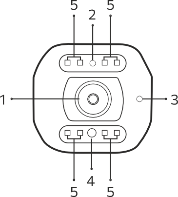
| № | Description |
|---|
| 1 | Lens |
| 2 | Indicator |
| 3 | Microphone |
| 4 | Light sensor |
| 5 | IR indicators |
Top view
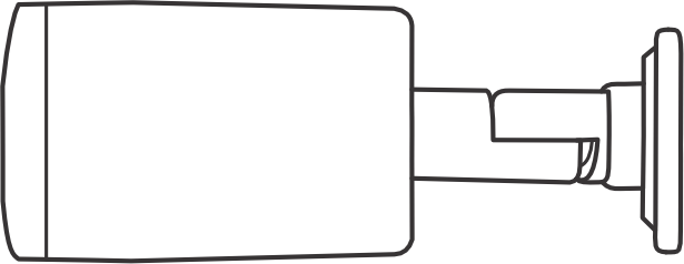
The top view of the camera is shown in the figure below.
Bottom view
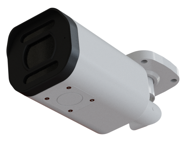
The bottom view of the camera is shown in the figure below.
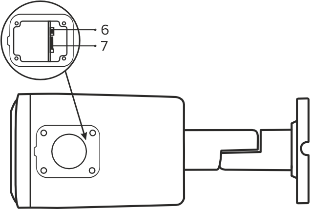
| № | Description |
|---|
| 6 | Reset button |
| 7 | MicroSD card slot |
Base view
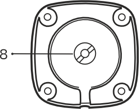
The base view of the camera is shown in the figure below.
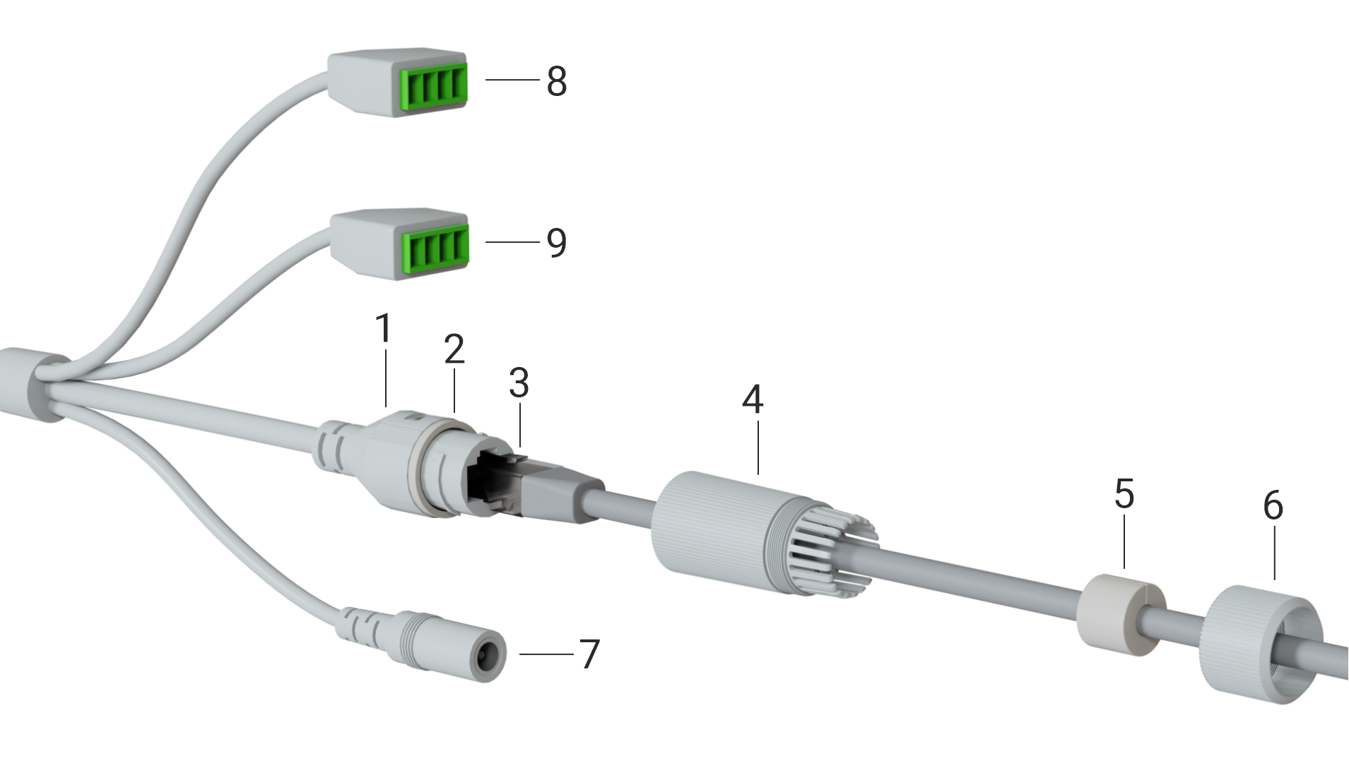
Cable design
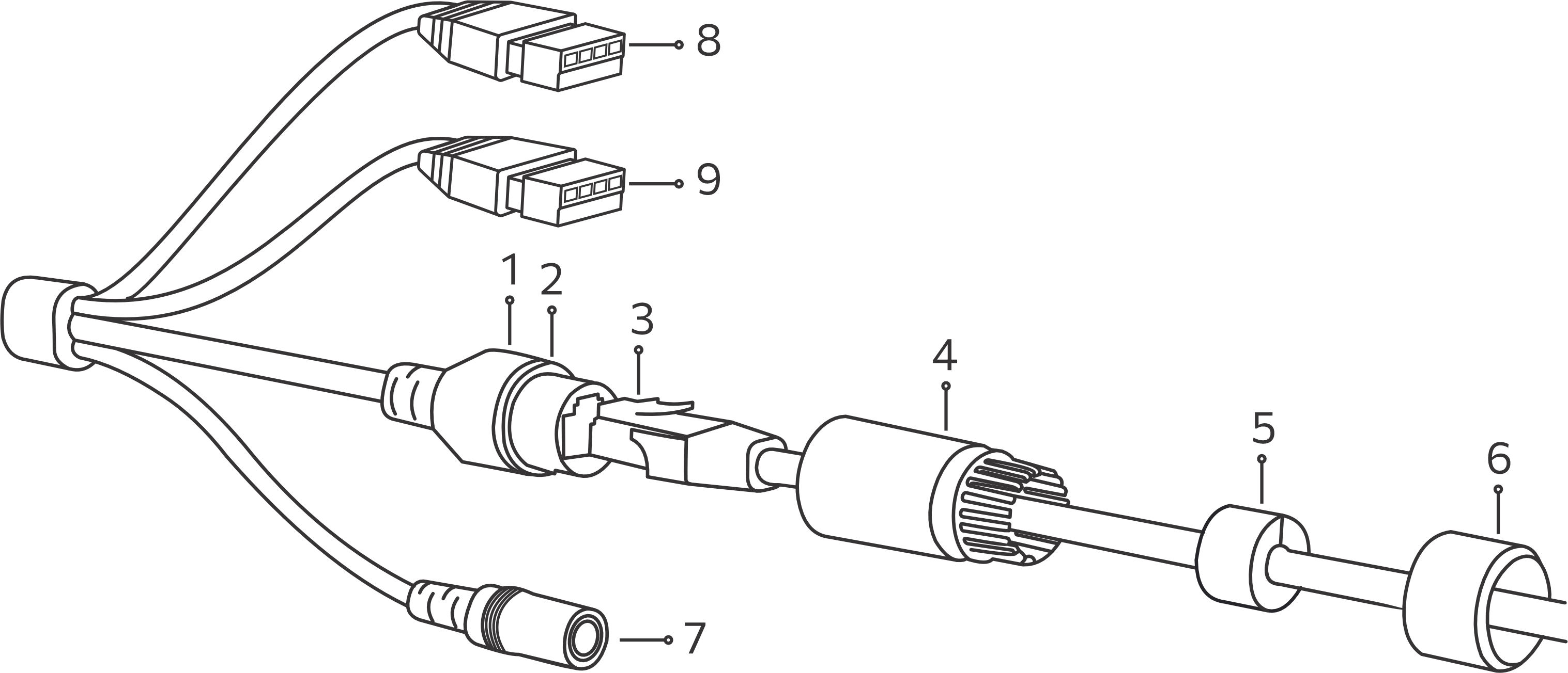
| № | Description |
|---|
| 1 | Network interface |
| 2 | Sealing ring |
| 3 | Ethernet cable |
| 4 | Cable gland |
| 5 | Waterproof ring |
| 6 | Locking nut |
| 7 | Power adapter connector |
| 8 | Alarm input/output |
| 9 | Connector for external speakers and a microphone |
Delivery package
SV-BB341Z-E2B standard delivery package includes:
- SV-BB341Z-E2B IP camera;
- Mounting kit;
- Case mounting template;
- Cable gland;
- Installation and initial configuration guide.
Reset to factory settings
There are two ways to perform a factory reset:
- Software reset. In the device web interface, enter "System settings", select "Configuration" and click "Reset to Factory Default Settings".
- Hardware reset. The reset button is located on the cable. Remove the protective cap, then press and hold the reset button for three seconds. The camera will then reboot.
Operating conditions
- The camera is designed for indoor and outdoor usage.
- Do not install the device near heat sources.
- Do not expose the device to smoke, dust, water or other liquids. Do not mechanically damage the device.
- Do not open the device case. There are no user-serviceable elements inside the camera.
- At the end of its service life, do not dispose of the camera with normal household waste. Take it to an electronics recycling center.
Device installation
Selecting the camera location
- Determine the areas that need to be monitored. Consider that entrance doors, windows, and various objects may obstruct the camera's field of view and reduce it.
- Pay attention to the lighting where the camera is installed to ensure a clear image. Avoid direct sunlight and other bright light sources directed at the camera lens. Also consider light sources that may create shadows or glare in the image.
- Consider the location of the power supply. The use of extension cords or additional cables is not recommended, as this may impair the quality of the power supply.
Mounting using a bracket
The device can be mounted on walls and ceiling. |
- Select a location for the camera based on the recommendations in the "Selecting a camera location" section.
- On the selected surface, mark where the four holes for the bracket will be drilled. Use the supplied template for this purpose.
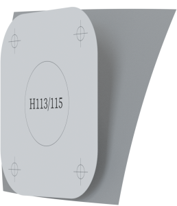
3. Separate the template from the backing and stick it to the wall.
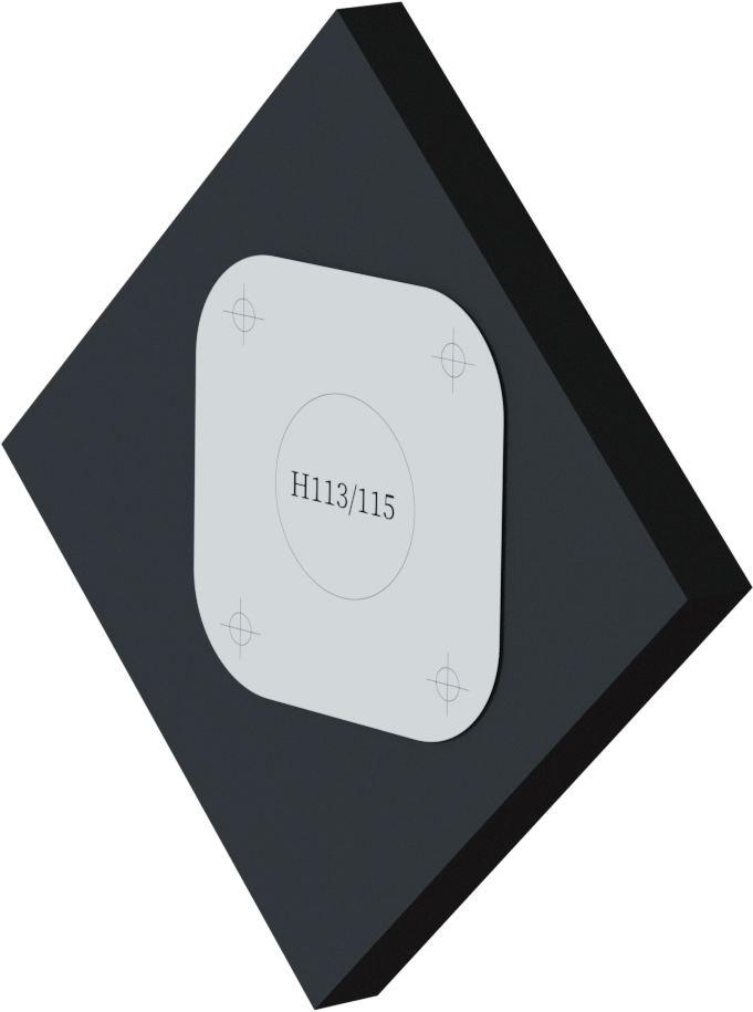
4. Drill four holes according to the template. Use dowels if necessary.
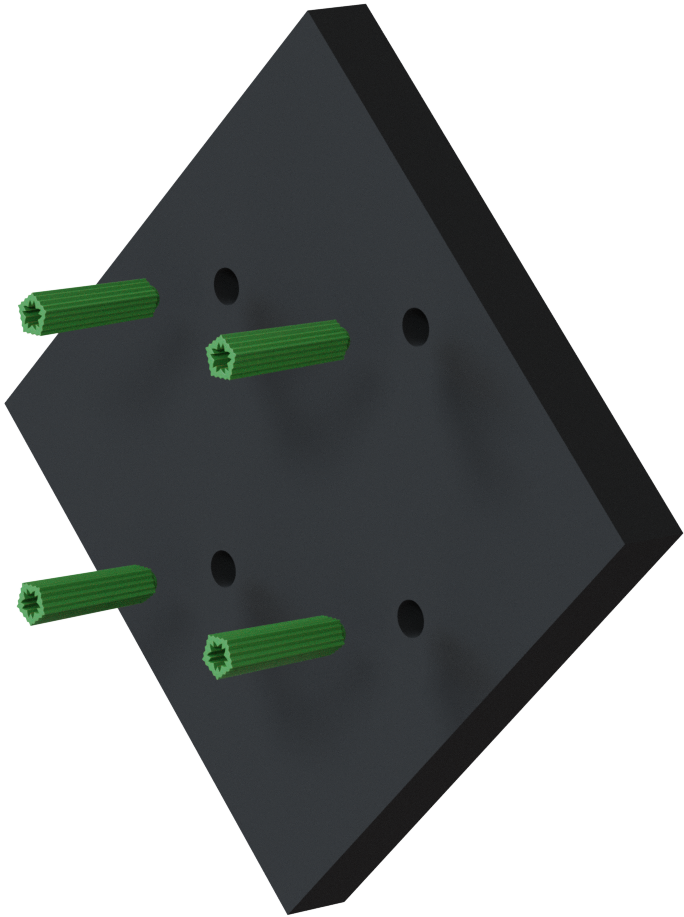
5. Align the holes on the wall with the holes on the bracket and fix the camera with screws.
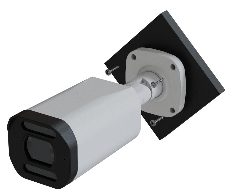
A view of the camera placed on the ceiling is shown in the figure below.
6. Connect the Ethernet cable in the order shown in the image below: slide the O-ring (2) over the sealing cap of the network interface (1). Place the locking nut (6) and the cable gland (4) on the Ethernet cable (3). Insert the Ethernet cable (3) into the network interface. Tighten the cable gland (4) and fix it to the sealing cap (1). Slide the waterproof ring (5) over the sealing ring (4). Make sure that the ring fits snugly over the connector. Tighten the locking nut (6) and fix it to the cable gland (4). Once the Ethernet cable is connected and insulated, connect the power cable to the power connector (7).
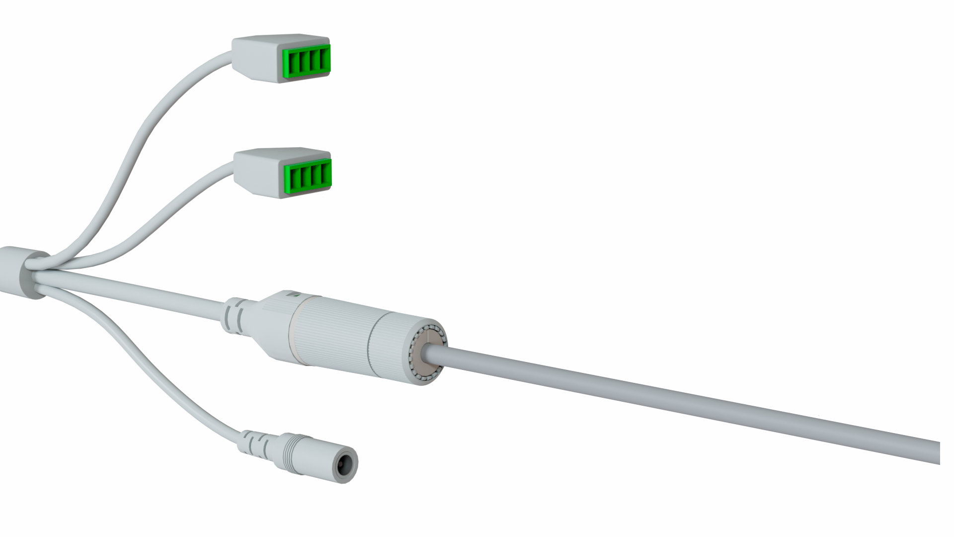
 The assembled cable is shown in the figure below.
Device management via the web interface
Getting started
- Connect the camera to the local network.
- Open a web browser and enter the device's IP address obtained from the DHCP server in the address bar, or the default IP address (192.168.1.123) if there is no DHCP server on the local network.
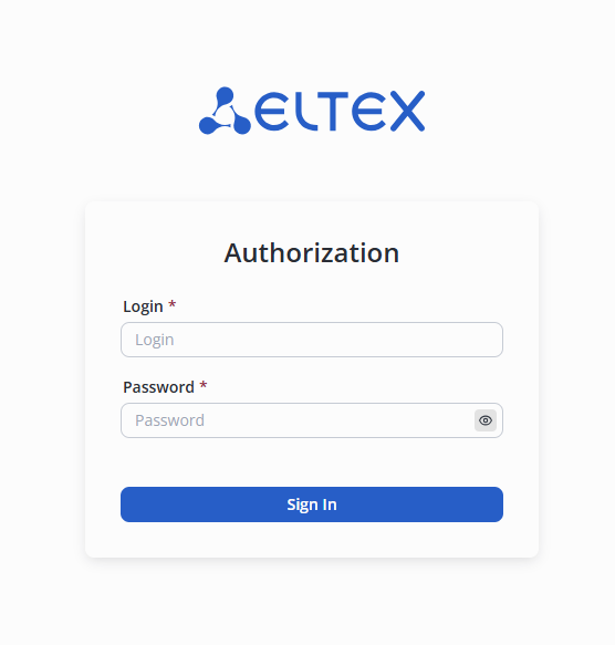
- The authorization page will be displayed in the browser window. Enter the username and password in the appropriate fields. (By default, the login is admin, the password is password).
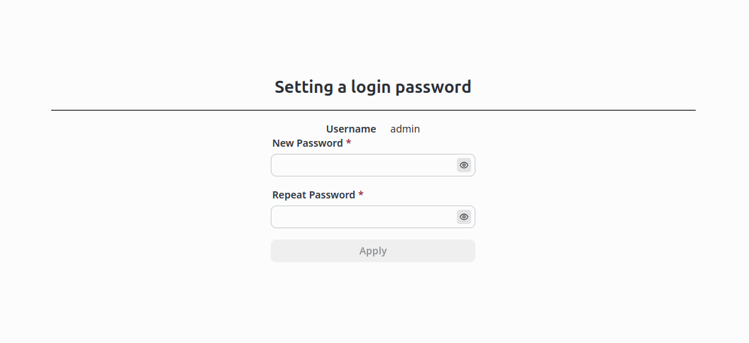
4. Click the "Sign in" button. The "Watch" page will open in the browser window.
5. If the camera has been rebooted or the cache has been cleared, the login and password entry page will open the next time you log in.
"Watch" tab
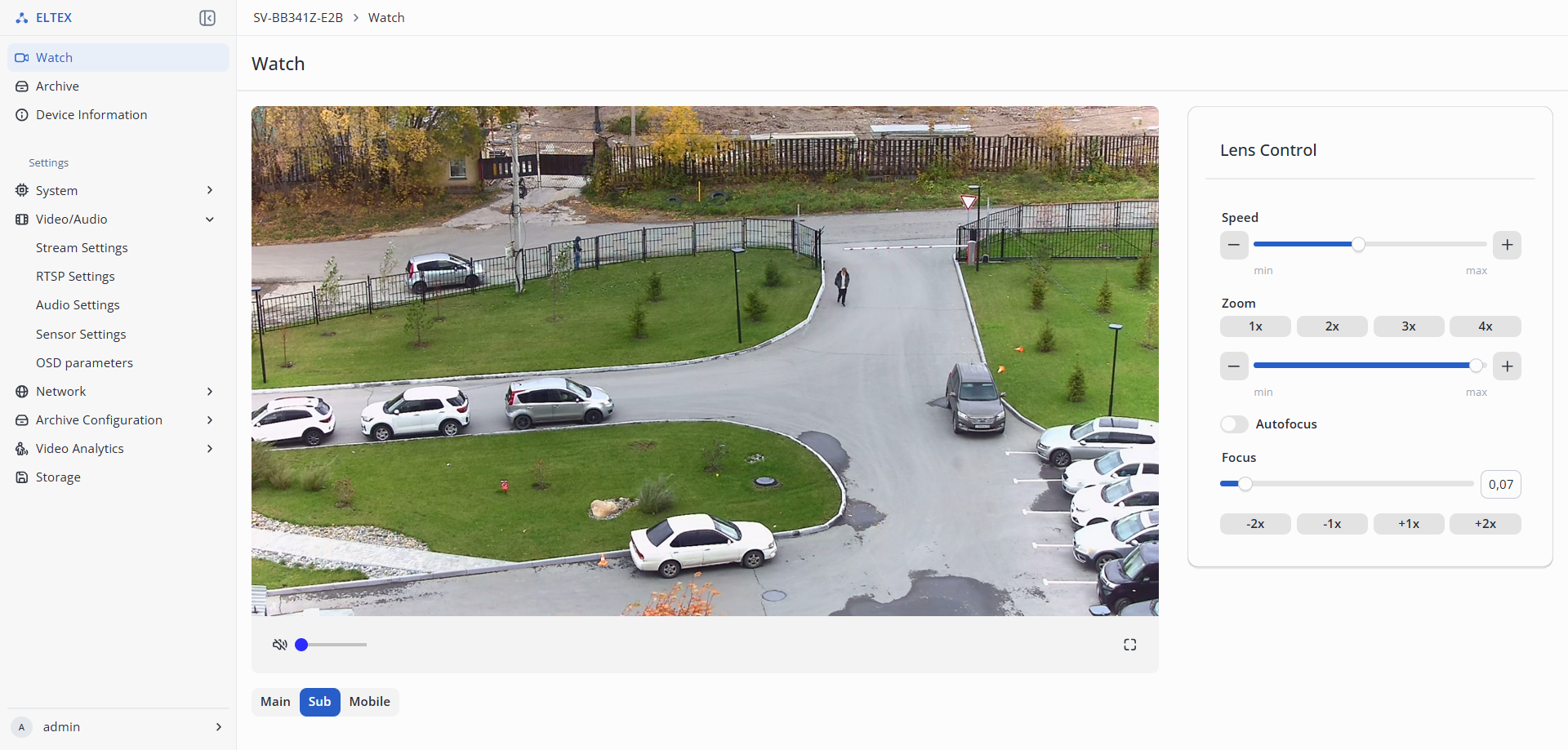
- Streams:
- Main — main stream, has better broadcast quality;
- Sub — secondary stream, has average broadcast quality;
- Mob — mobile stream, has low broadcast quality.
- Lens Control:
- Speed — the lens's focusing speed;
- Zoom — optical image magnification;
- Autofocus — automatic lens focusing;
- Focus — manual lens focusing.
"Archive" tab
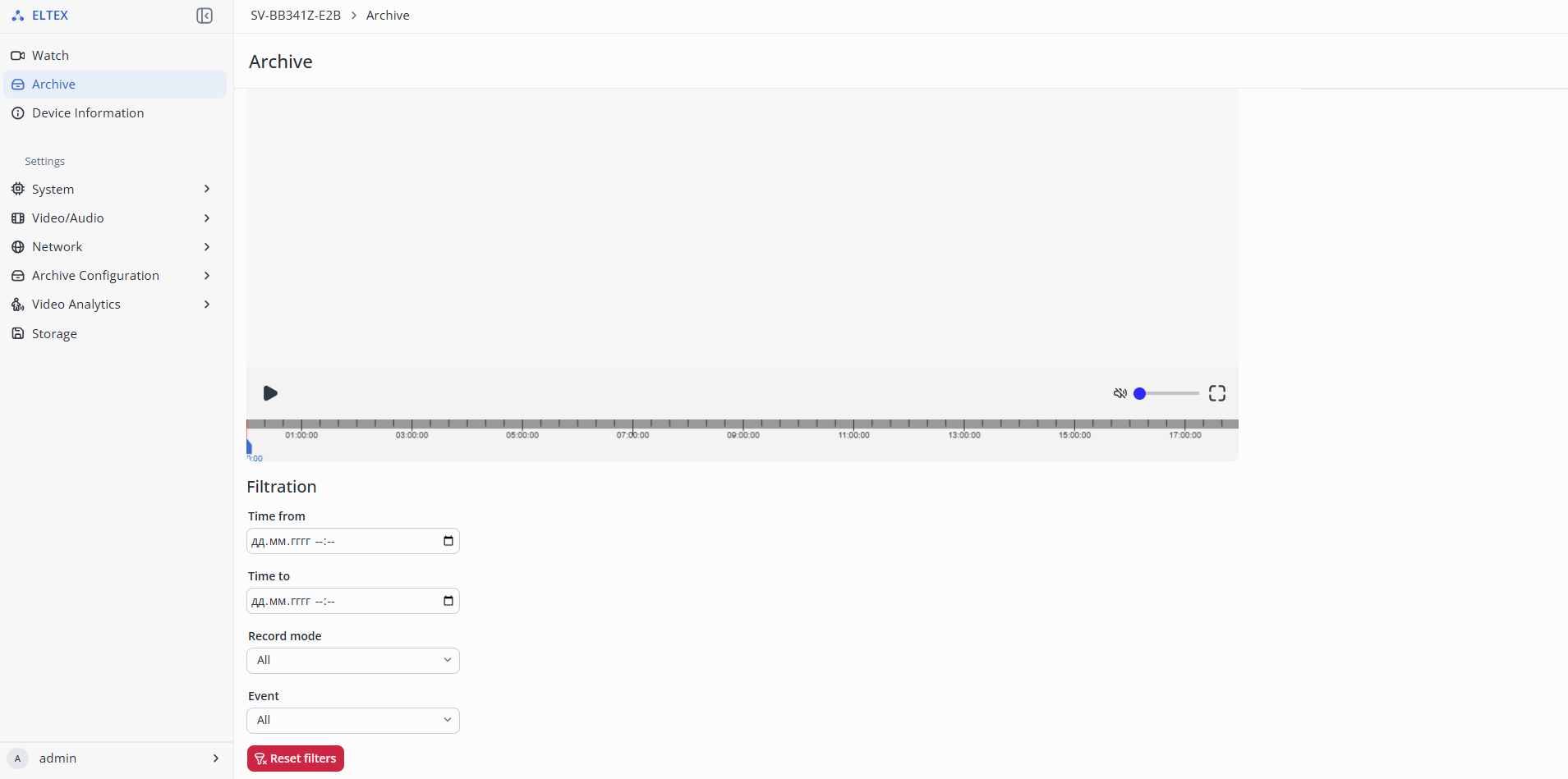
- Filtration — searching for records by specified parameters.
- Time from — filtering media files recorded starting from the specified date and time;
- Time to — filtering media files recorded up to the specified date and time;
- Record mode:
- All — displaying all media files;
- Permanent recording — displaying media files with the "Permanent recording" mode;
- Event recording — displaying media files with the "Event recording" mode.
- Event:
- All — displaying all media files;
- Motion — displaying media files with the "Motion" recording mode.
"Settings" tab
"Device Information" menu
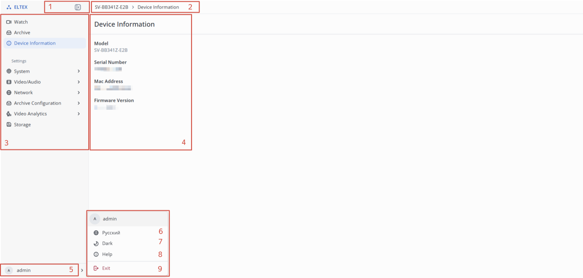
- Collapse the sidebar;
- Menu tabs;
- Menu items;
- Device information:
- Model — device model name;
- Serial Number — device serial number;
- MAC Address — device MAC address;
- Firmware version — current device firmware version.
- Username;
- Web interface language;
- Web interface theme — dark and light;
- Web interface help;
- Logout.
"System" tab
"Date And Time"
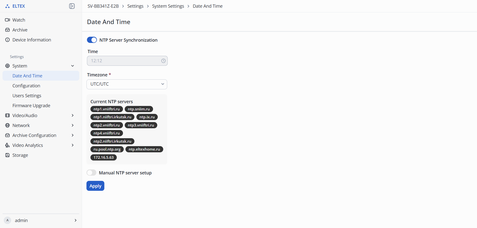
- NTP Server Synchronization — enabling NTP synchronization;
- Time — camera time. Can be edited if synchronization is not enabled;
- Timezone — camera time zone;
- NTP Server — NTP server address.
To save the settings, click the "Apply" button.
"Configuration"
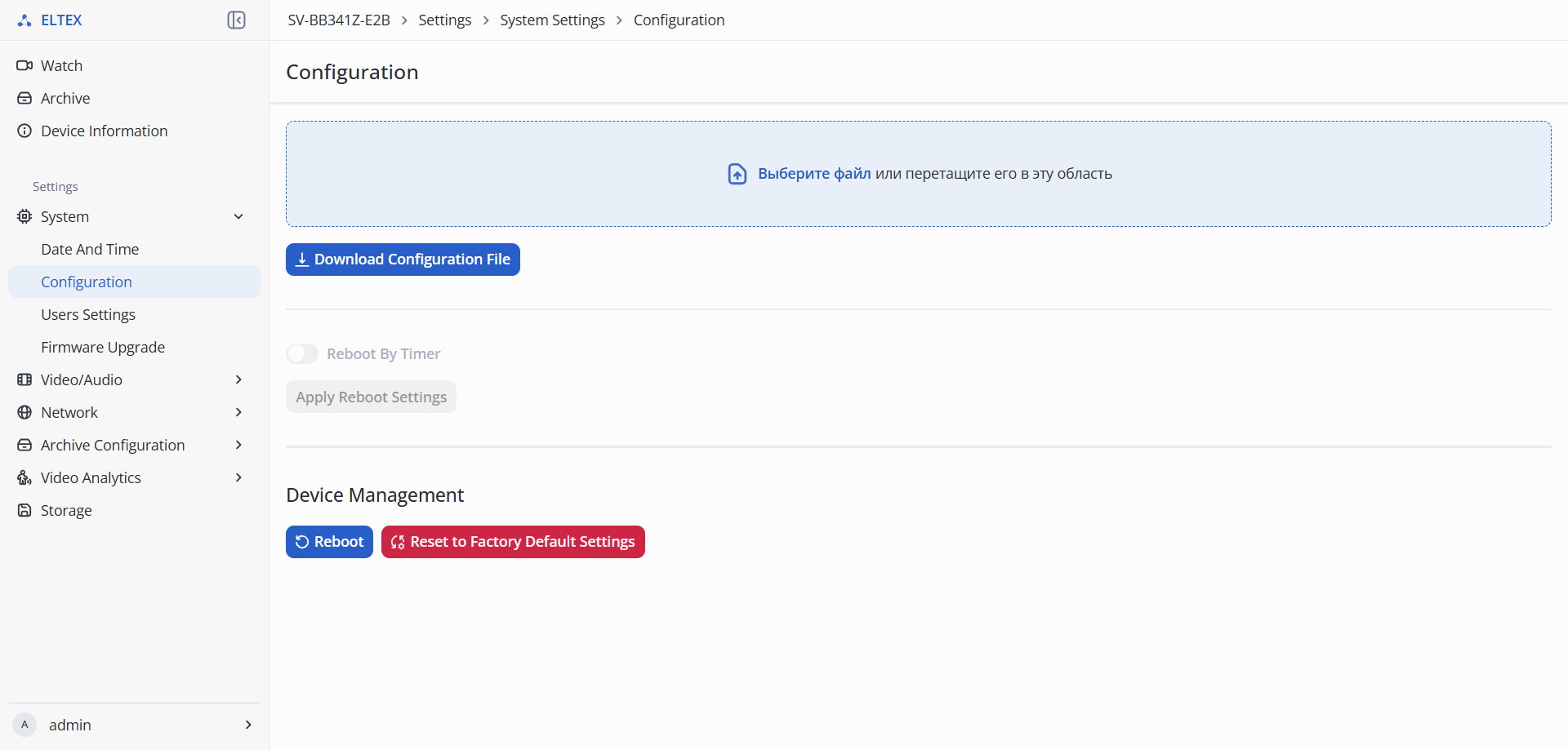
- Configuration — section for working with the device configuration:
- Download Configuration File — export the device configuration for further use.
- Reboot By Timer — section for configuring automatic weekly reboot:
- Day — the day of the week when the reboot will occur;
- Time — the exact time when the reboot will occur.
- Device Management:
- Reboot Device;
- Reset to Factory Default Settings.
To save the settings, click the "Apply" button.
"Users Settings"
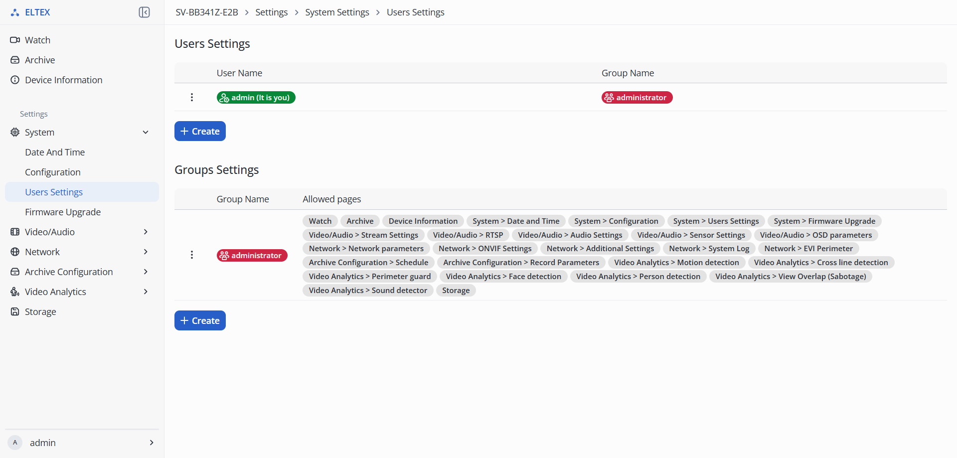
- Users Settings — creating a camera user for interaction with the web interface:
- User Name — user login;
- Group Name — group with specific access rights;
- Actions:
- Edit — change existing user parameters;
- Remove — delete user;
- Create — create a new user group.
- Group Settings — group and access rights settings:
- Group Name — group name;
- Actions:
- Edit — change existing user parameters;
- Remove — delete group.
"Firmware Upgrade"
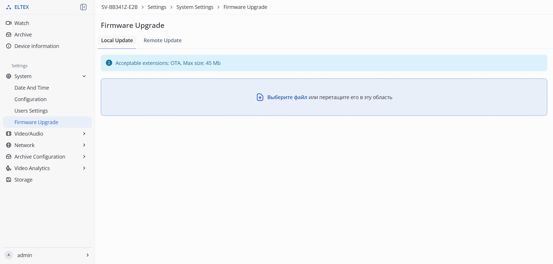
- Local Update — firmware update via a file downloaded to the device.
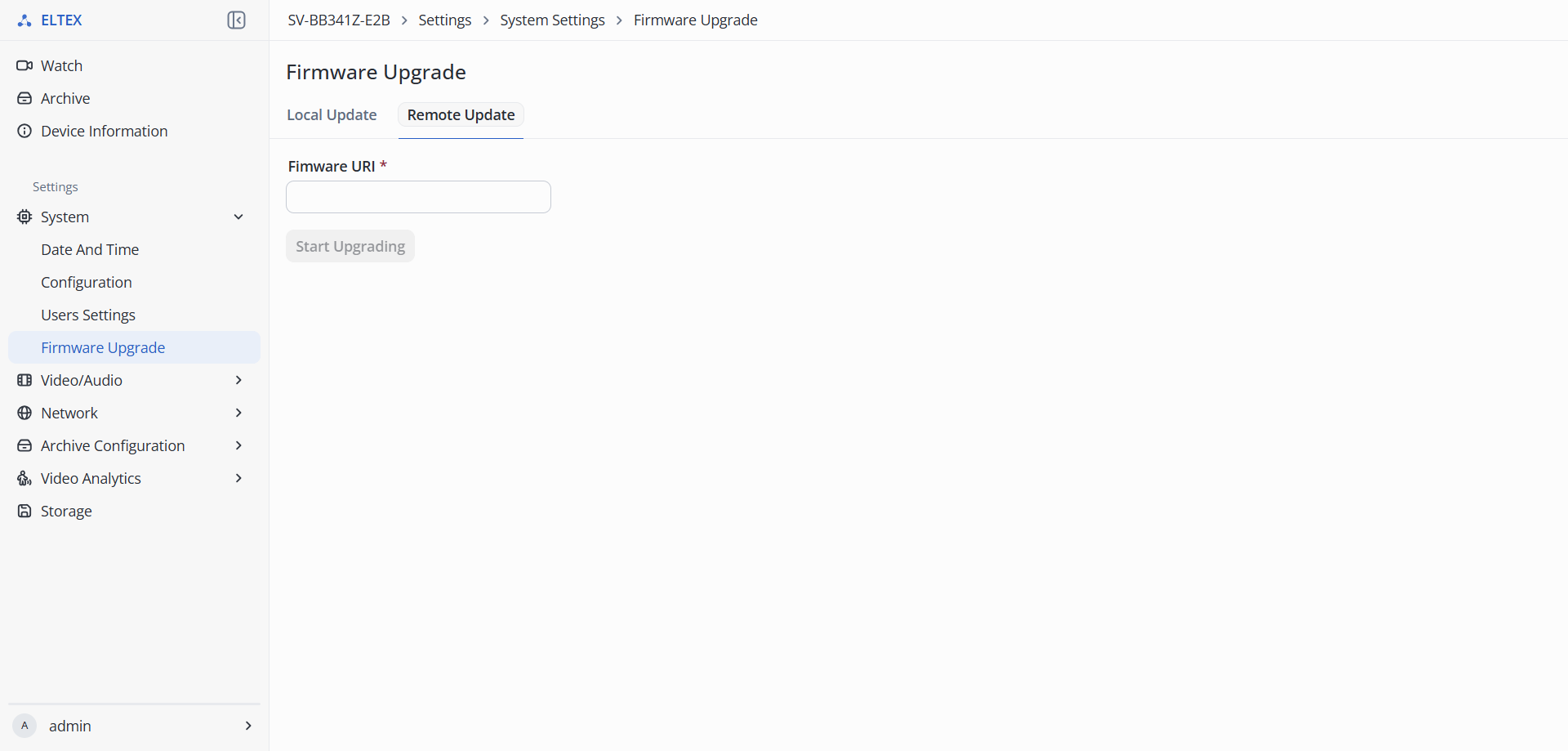
- Remote Update — update via a URI link from which the camera can download the firmware for the update.
To start the update, press the "Start Upgrading" button.
"Video/Audio" menu
"Stream Settings"
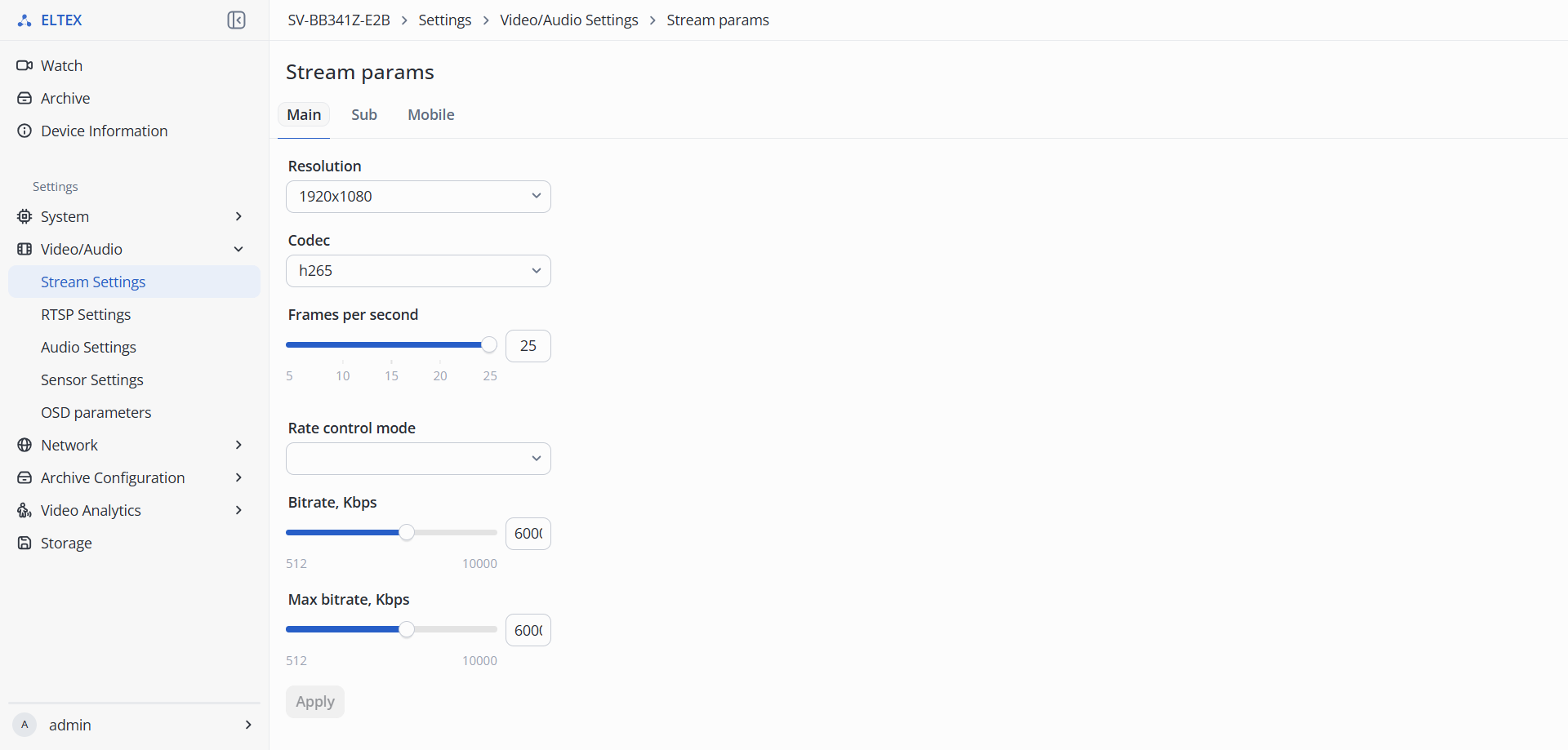
- Streams:
- Main — main stream, has the best broadcast quality;
- Secondary — secondary stream, has average broadcast quality;
- Mobile — mobile stream, has low broadcast quality.
- Stream params:
- Resolution — selection of the image resolution transmitted from the camera:
- Codec — selection of the video compression standard:
- Profile — selection of codec feature set:
- H.264 High Profile;
- H.264 Main Profile.
- Frames per second — number of frames that will be transmitted per second. The maximum frequency is 30 frames per second;
- Rate control mode — stream encoding mode:
- Constant bitrate — mode in which the stream has a constant bitrate set in the "Bitrate" field;
- Variable bitrate — mode in which the stream has a variable bitrate. The bitrate varies with the complexity of the image but does not exceed the "Maximum bitrate" value and on average adheres to the "Bitrate" value.
- Bitrate — amount of information transmitted by the camera. Increasing this parameter proportionally increases the quality of the transmitted image. Maximum bitrate — 6000 kbps.
To save the settings, click the "Apply" button.
"RTSP Settings"
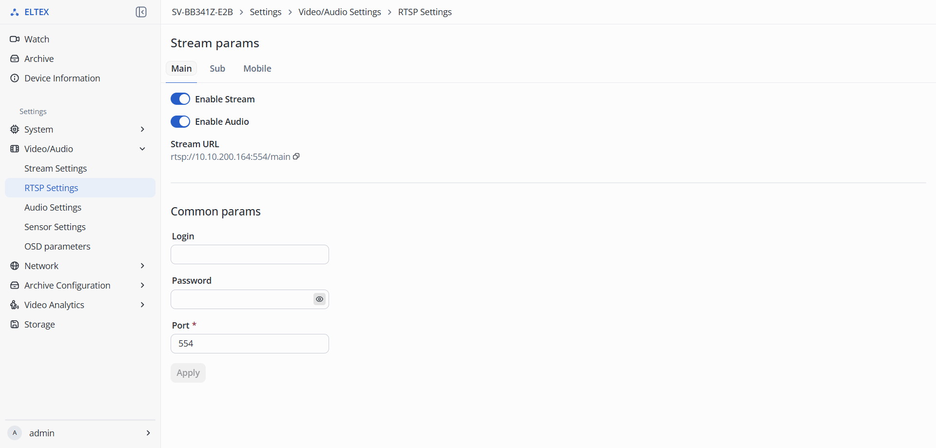
- Streams:
- Main — main stream, has the best broadcast quality;
- Secondary — secondary stream, has average broadcast quality;
- Mobile — mobile stream, has low broadcast quality.
- Sream params — section for configuring RTSP streaming:
- Enabled — enable and disable the stream;
- Audio — enable and disable audio in the stream;
- Stream URL — link to the selected stream considering the fields "Login", "Password", and "Port" in the "Common params" section.
- Common params:
- Login — username up to 63 characters in Latin alphabet and numbers;
- Password — user password up to 63 characters in Latin alphabet and numbers;
- Port — port through which the stream can be obtained from the RTSP server.
To save the settings, click the "Apply" button.
"Audio Settings"
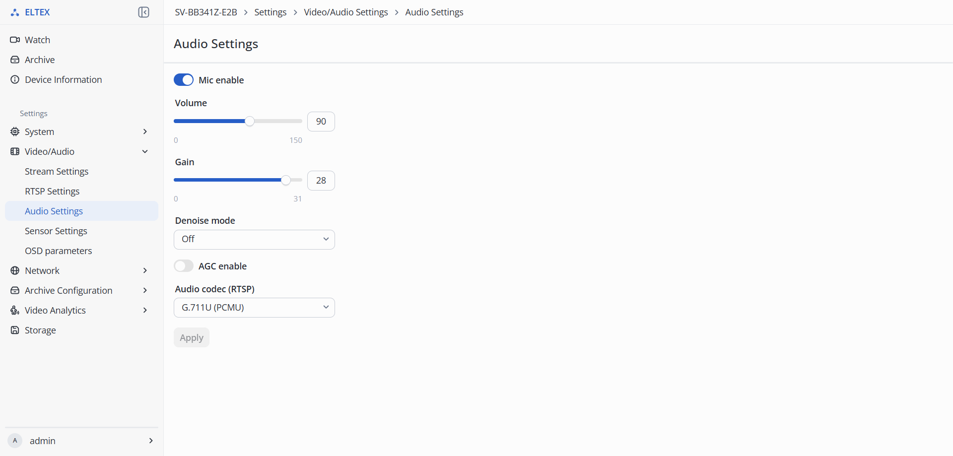
- Mic enable — enabling and disabling the microphone;
- Volume — microphone volume. Maximum value — 150 dB;
- Gain — microphone volume gain. Maximum value — 31 dB;
- Denoise mode:
- Off — noise damping off;
- Low — low noise damping;
- Medium — medium noise damping;
- High — high noise damping;
- Max — maximum noise damping.
- AGC enable:
- Volume — automatic microphone gain volume;
- Gain — microphone volume gain.
- Audio codec (RTSP) — selection of audio compression standard:
To save the settings, click the "Apply" button.
"Sensor Settings"
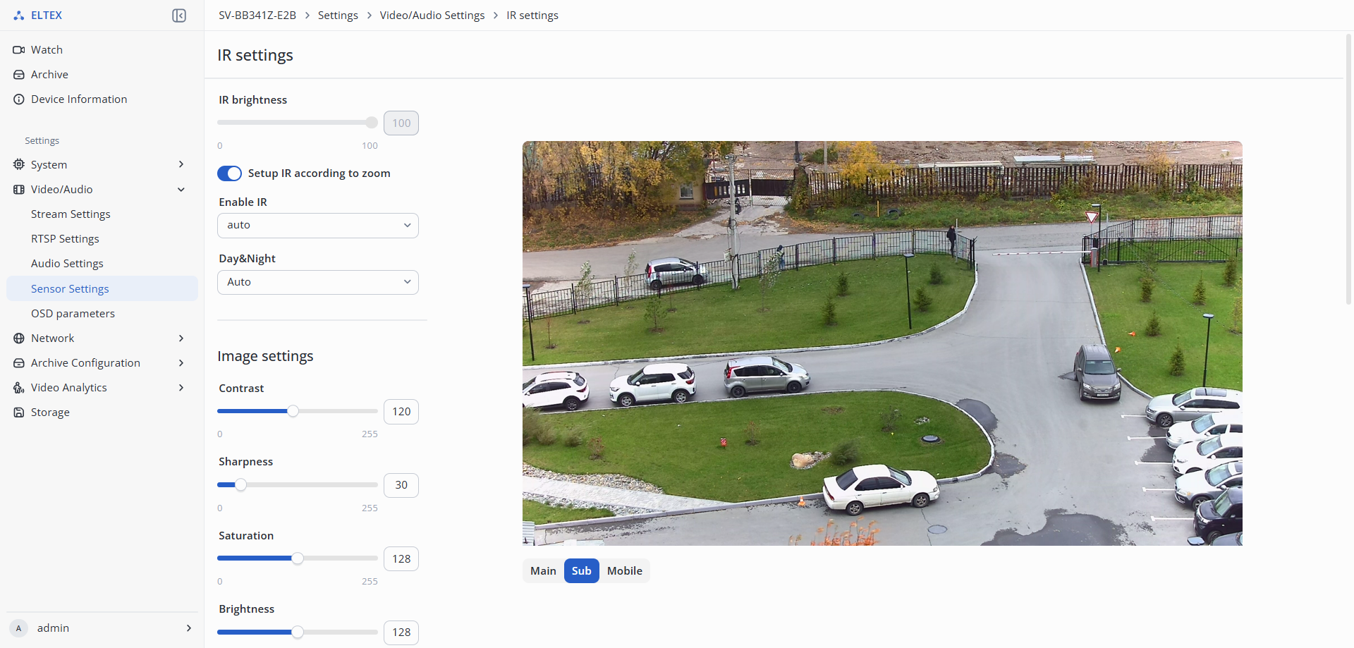
- IR settings:
- IR brightness;
- Enable IR:
- Day&Night — selection of infrared illumination mode:
- Auto — automatic switching between day and night mode based on light level;
- Day — infrared illumination is always off;
- Night — infrared illumination is always on.
- Image settings:
- Contrast — image contrast. It is possible to set a value in the range from 0 to 255. The default value is 128;
- Sharpness — image sharpness. It is possible to set a value in the range from 0 to 255. The default value is 90;
- Saturation — image saturation. It is possible to set a value in the range from 0 to 255. The default value is 128;
- Brightness — image brightness. It is possible to set a value in the range from 0 to 255. The default value is 128;
- White balance — used to adjust the color temperature depending on the environment:
- auto — automatic configuration;
- day — daylight;
- cloud — cloudy;
- inc — incandescent lamp;
- fluo — fluorescent light;
- twi — twilight;
- shade — shade;
- warm_fluo — warm fluorescent light.
- Image orientation — camera image management:
- Default — camera transmits the image as the user sees it with their own eyes;
- Vertical Flip — image is reflected along the vertical axis;
- Horizontal Flip — image is reflected along the horizontal axis;
- 180 Rotation — image is reflected vertically and horizontally, thus providing an image as in "Standard" mode for a physically inverted camera.
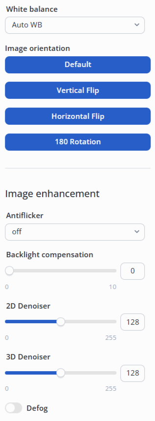
- Image enhancement:
- Antiflicker — compensation for lamp flicker from power grids of different frequencies:
- Backlight compensation — elimination of darkening when the object is against a bright light source. It is possible to set a value in the range from 0 to 10;
- 2D Denoiser — noise damping in each frame by analyzing neighboring pixels. It is possible to set a value in the range from 0 to 255. Default value — 128;
- 3D Denoiser — noise damping by analyzing both neighboring pixels and changes between frames. It is possible to set a value in the range from 0 to 255. Default value — 128;
- Defog — increasing image clarity and contrast in poor visibility conditions caused by fog or haze:
- Strength — it is possible to set a value in the range from 0 to 255. Default value — 128.
- DWDR:
- Enable WDR — improving image visibility with any lighting level fluctuations:
- Strength — degree of brightening dark areas. It is possible to set a value in the range from 0 to 255;
- Hilight — degree of suppression of bright areas. It is possible to set a value in the range from 0 to 10.
"OSD parameters"
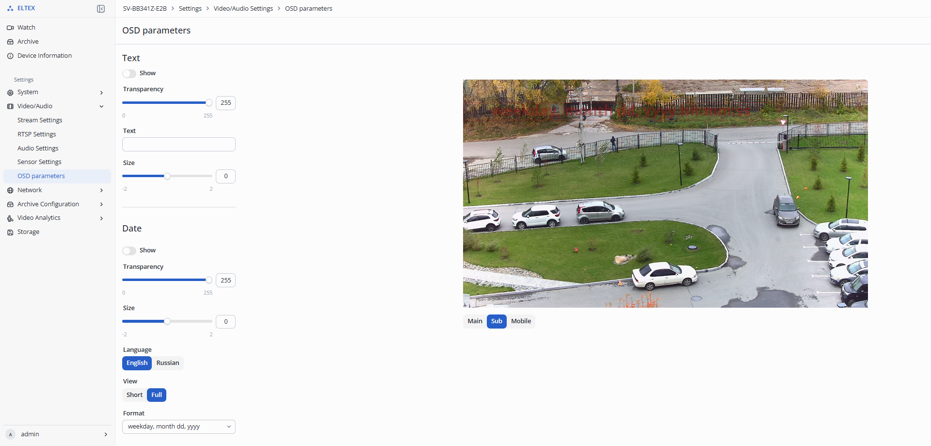
- OSD — On-Screen Display, text displayed on the screen;
- Text:
- Show — enable the display of user text;
- Transparency — transparency of the displayed text. It is possible to set a value in the range from 0 to 255;
- Text — field for entering text to display.
- Date:
- Show — enable the display of the date;
- Transparency — transparency of the displayed date. It is possible to set a value in the range from 0 to 255.
"Network" menu
"Network Parameters"
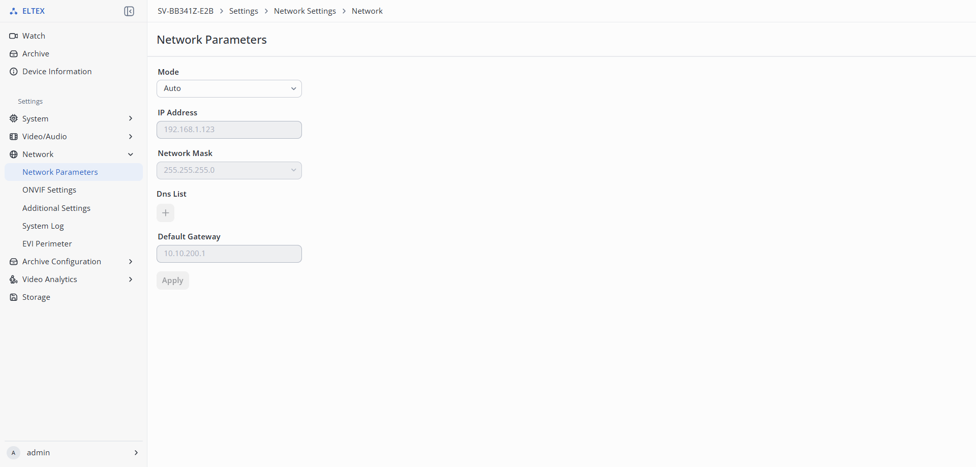
- Mode:
- Auto — obtaining all settings via DHCP;
- Manual — setting all network parameters manually:
- IP Address;
- Network Mask;
- Dns List — addresses of DNS servers;
- + — adding a backup DNS server;
- Default Gateway.
To save the settings, click the "Apply" button.
"ONVIF Settings"
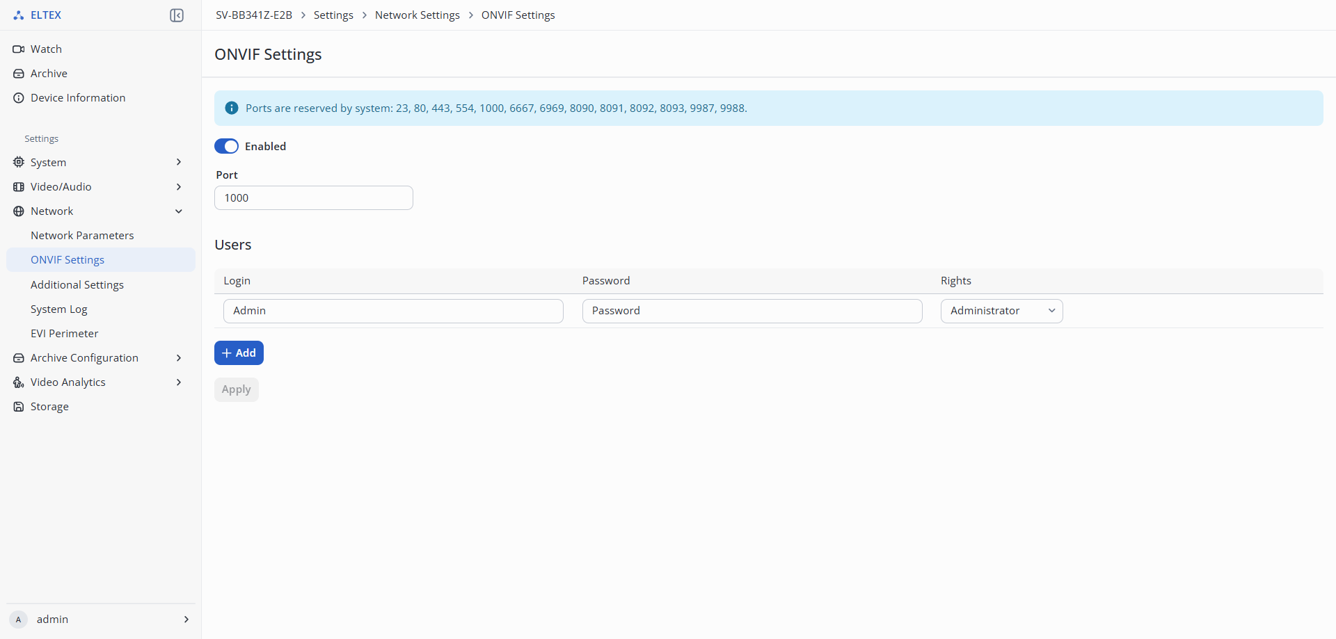
- Enabled — enabling the ONVIF protocol;
- Port — port through which the camera will interact with control systems via the ONVIF protocol. By default, port 1000 is used;
When configuring ports, it is necessary to pay attention to the ports reserved by the system to avoid port conflicts. Ports reserved by the system: 23, 80, 443, 554, 1000, 6667, 6969, 8090, 8091, 8092, 8093, 9987, 9988. |
- Users — creating users with specific access rights:
- Login — user login;
- Password — user password;
- Rights — user access level:
- Administrator — full access to all device functions;
- Operator — access to basic device functions. Cannot change settings or manage users;
- Media user — limited access (view only). No rights to change configuration;
- Anonymous — minimal rights (if allowed in settings). Usually view only without authorization.
To save the settings, click the "Apply" button.
"Additional Settings"
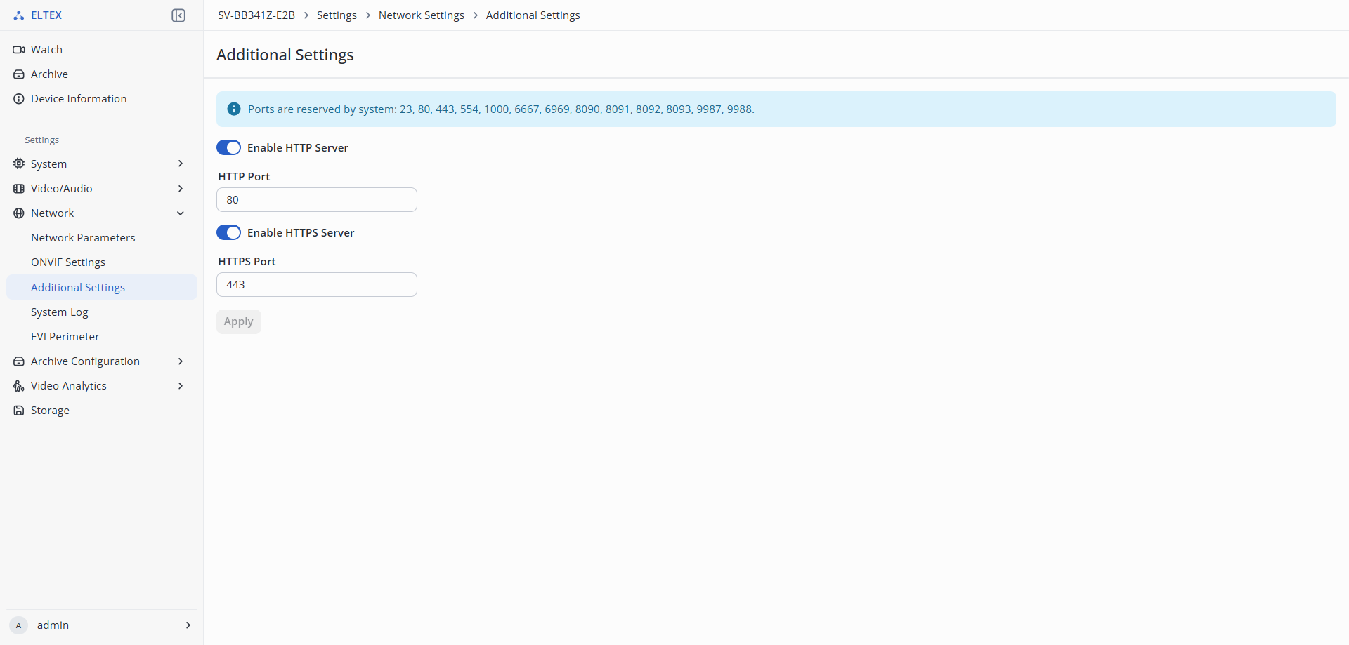
- Enable HTTP Server — access to the camera's web interface via the HTTP protocol;
- HTTP Port — port through which interaction with the camera's web interface via the HTTP protocol will be carried out. By default, port 80 is used;
When configuring ports, it is necessary to pay attention to the ports reserved by the system to avoid port conflicts. Ports reserved by the system: 23, 80, 443, 554, 1000, 8090, 8091, 8092, 8093. |
- Enable HTTPS Server — access to the camera's web interface via the HTTPS protocol;
- HTTPS Port — port through which interaction with the camera's web interface via the HTTPS protocol will be carried out. By default, port 443 is used.
To save the settings, click the "Apply" button.
"System Log"
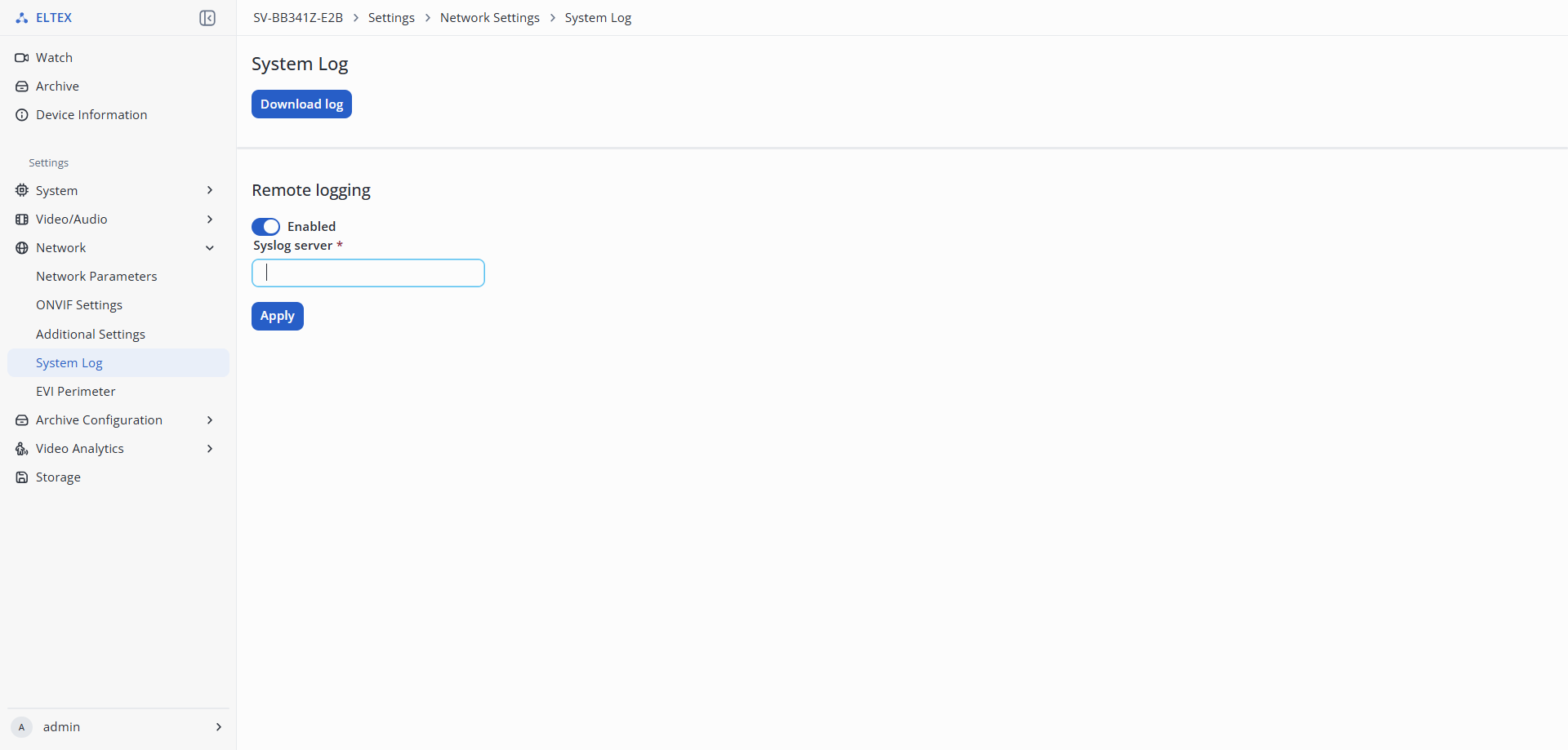
- Download log — download system log;
- Remote logging — section for configuring logs to a remote server:
- Syslog server — address of the remote syslog server.
To save the settings, click the "Apply" button.
«EVI Perimeter»
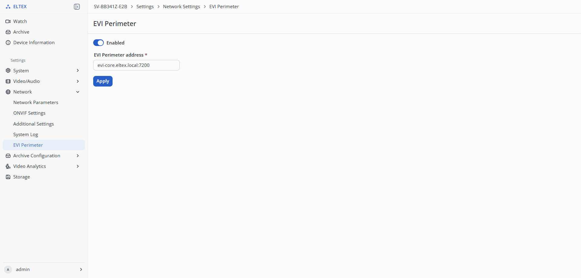
- Enabled — enables integration with EVI Perimeter;
- EVI Perimeter address — the address of the EVI platform.
"Archive Configuration" menu
"Schedule"
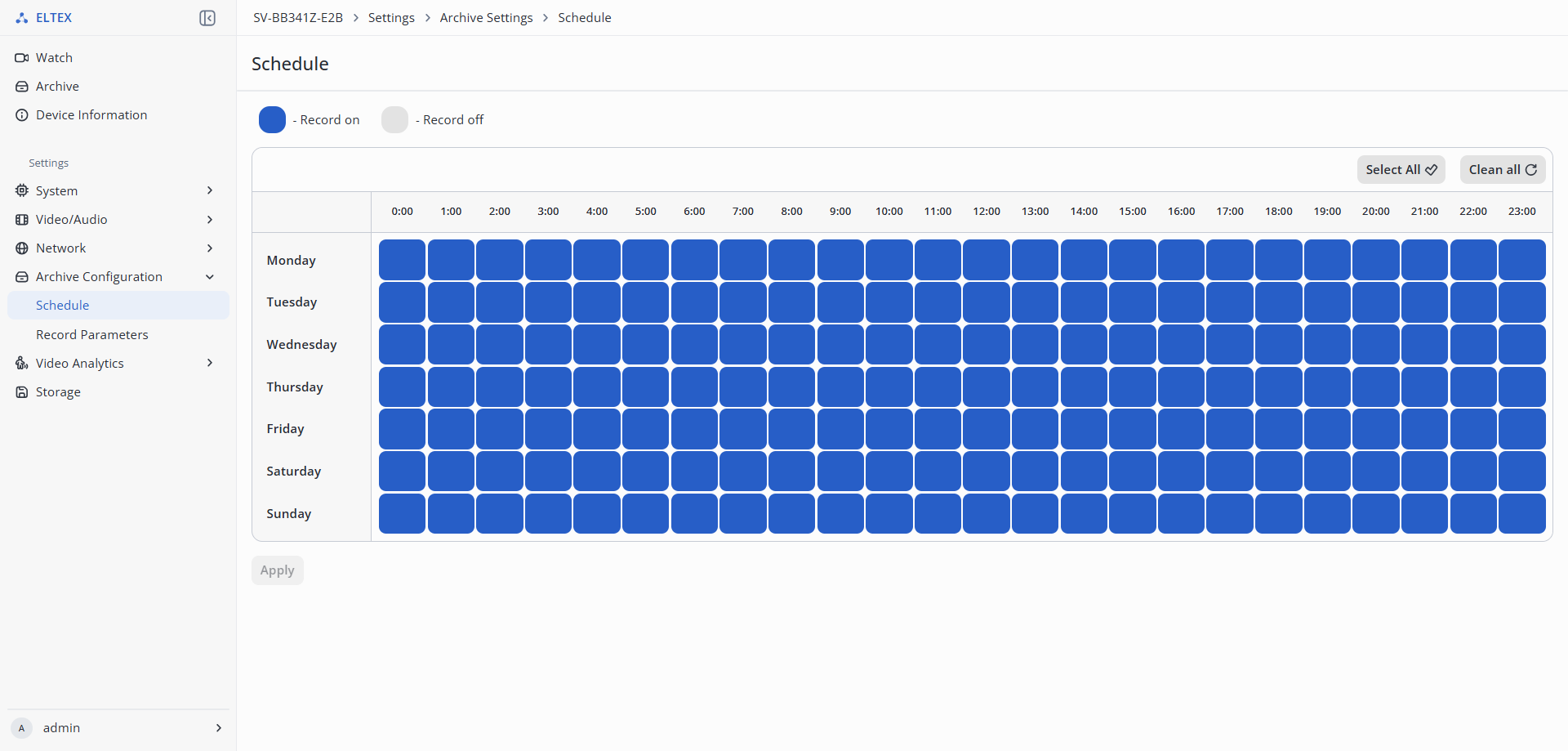
- Schedule — setting the period during which the camera will record. To select the necessary intervals, highlight them by clicking the left mouse button.
To save the settings, click the "Apply" button.
"Record Parameters"
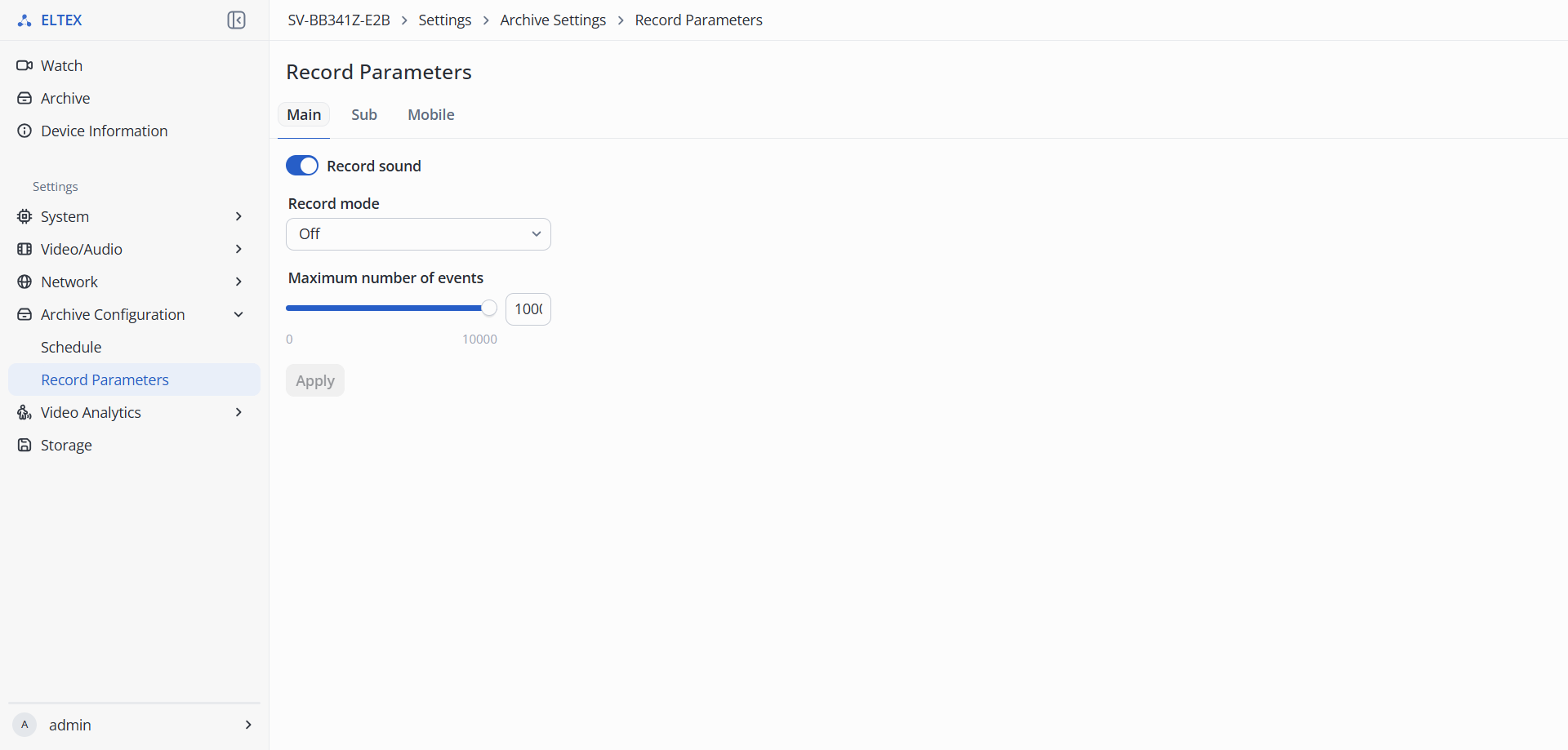
- Streams:
- Main — main stream, has the best broadcast quality;
- Secondary — secondary stream, has average broadcast quality;
- Mobile — mobile stream, has low broadcast quality.
- Record sound — enable/disable the microphone during recording.
- Record:
- Permanent recording — video recording is permanent;
- Event recording — video recording occurs only when an event is detected;
- Off — video recording is not conducted.
- Maximum number of events — saving a set number of events to a MicroSD card. If the number of events is exceeded, old recordings will be overwritten. It is possible to set a value in the range from 0 to 10000;
To save the settings, click the "Apply" button.
"Video Analytics" menu
It is possible to use the “Motion detection”, “Cross line detection”, “Perimeter guard”, and “View obstruction” analytics simultaneously. The “Face detection” and “Person detection” analytics can only be used separately from the analytics listed above. |
"Motion detection"
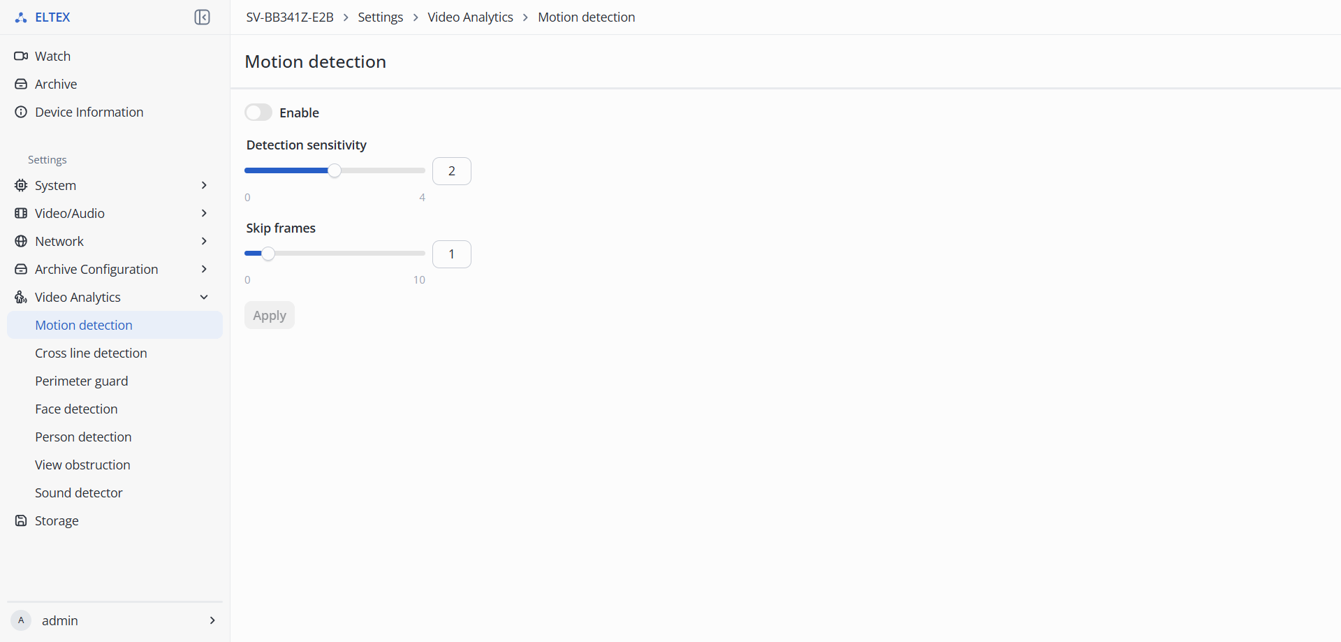
- Motion detection:
- Enable — enable/disable video analytics for Motion detection.
- Detection sensitivity — parameter that controls the sensitivity of motion detection. Sensitivity values range from 0 to 4; the higher the value, the smaller the objects that will be detected.
- Skip frames — parameter that determines how many intermediate frames the algorithm skips between scene analysis points. During scene analysis, every n frame will be used, where n can range from 0 to 10.
To save the settings, click the "Apply" button.
"Cross line detection"
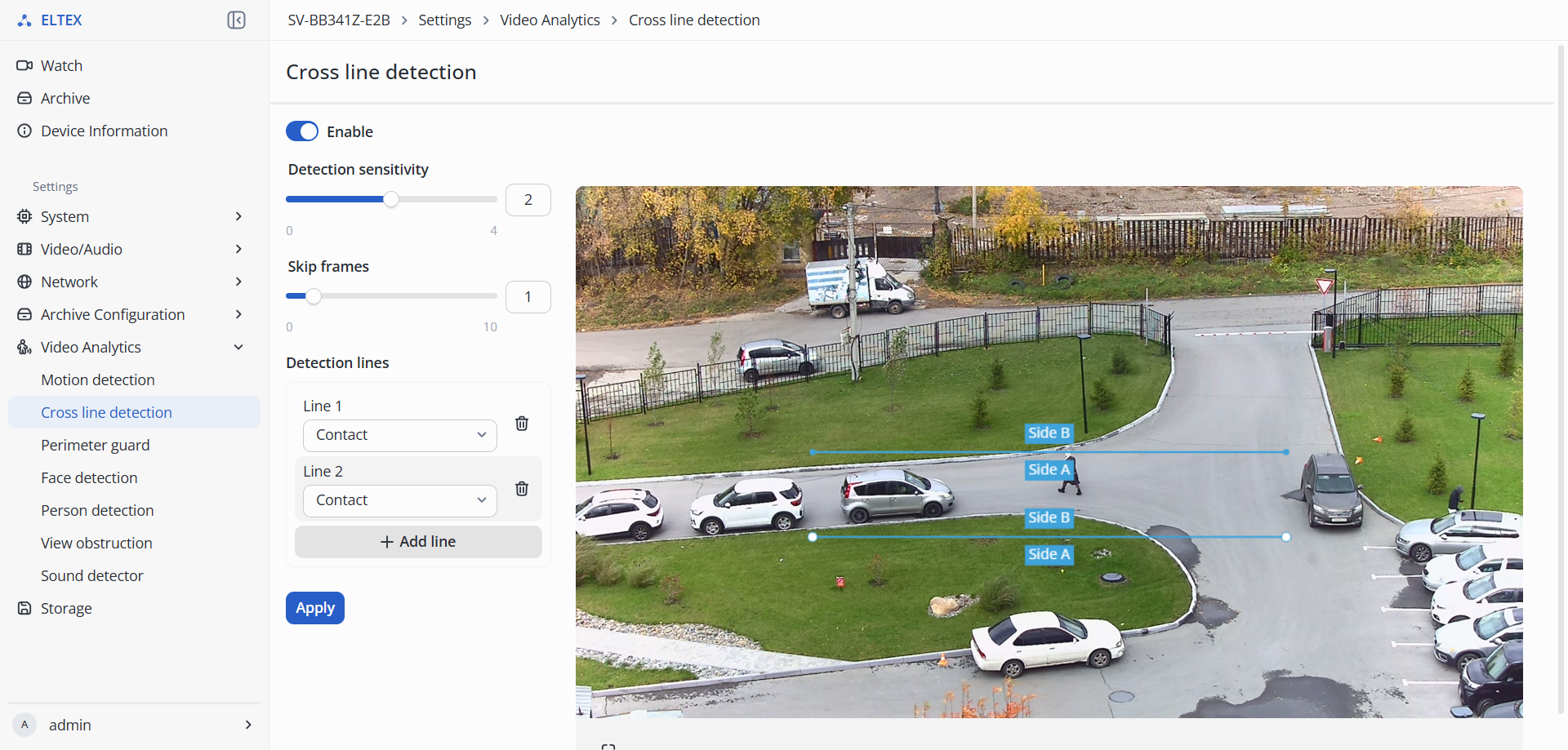
- Cross line detection:
- Enable — enable/disable video analytics for Cross line detection.
- Detection sensitivity — parameter that controls the sensitivity of motion detection. Sensitivity values range from 0 to 4; the higher the value, the smaller the objects that will be detected;
- Skip frames — parameter that determines how many intermediate frames the algorithm skips between scene analysis points. During scene analysis, every n frame will be used, where n can range from 0 to 10;
- Detection lines — list of added lines. In this section, use the “Add line” button to add a line or the trash can button to delete a line;
- Add line — add a line and specify the detection criteria when the line is crossed:
- Contact — object is detected when it contacts the line;
- Two way cross — object is detected when it crosses the line in either direction;
- B→A transition — detection occurs when an object crosses the line from side B toward side A;
- A→B transition — detection occurs when an object crosses the line from side A toward side B.
To save the settings, click the "Apply" button.
"Perimeter guard"
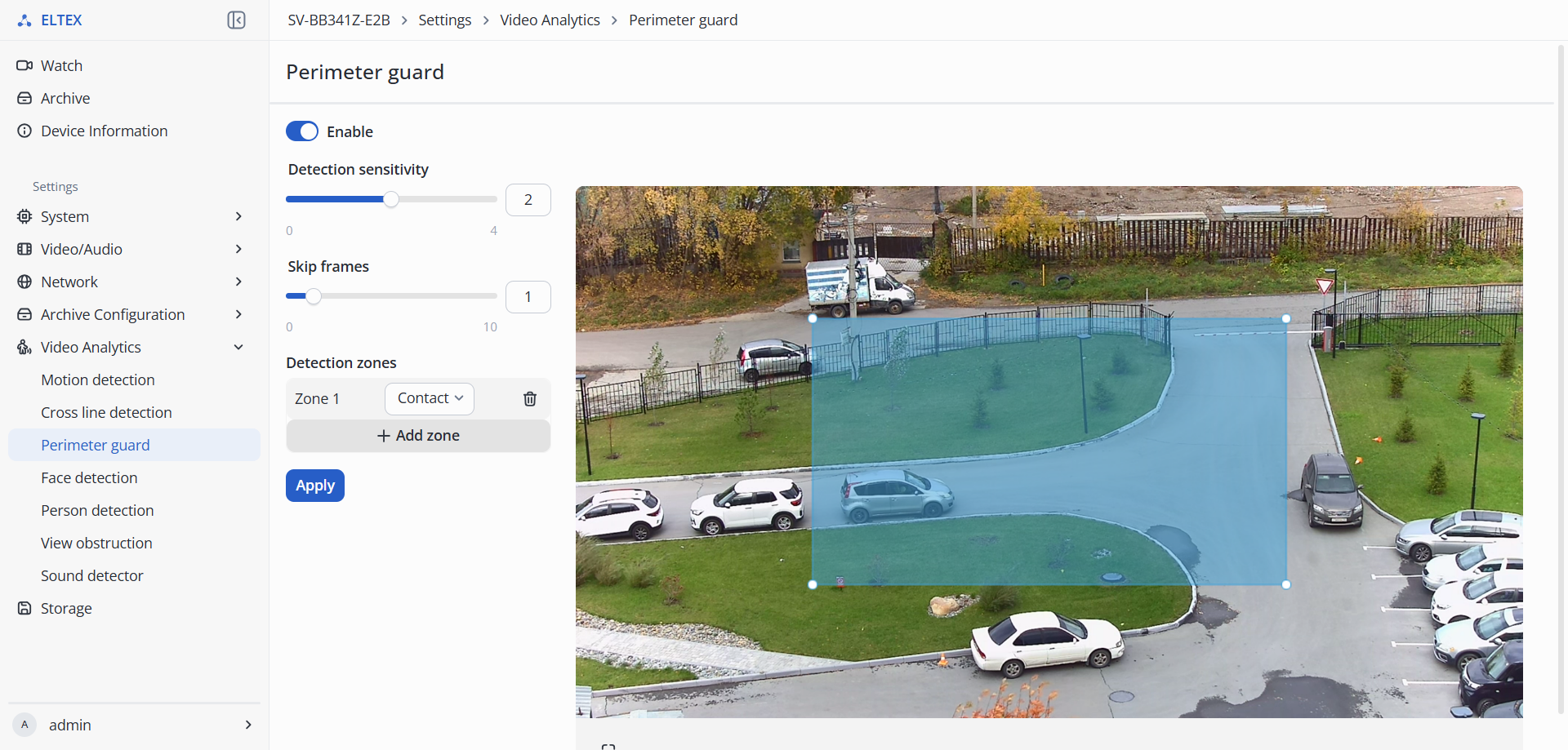
- Perimeter guard:
- Detection sensitivity — parameter that controls the sensitivity of motion detection. Sensitivity values range from 0 to 4; the higher the value, the smaller the objects that will be detected;
- Skip frames — parameter that determines how many intermediate frames the algorithm skips between scene analysis points. During scene analysis, every n frame will be used, where n can range from 0 to 10;
- Detection zones — list of added detection zones. In this section, use the “Add zone” button to add zones or the trash can button to delete a zone;
- Add zone — add a zone and specify the detection criteria for that zone:
- Contact — object is detected when it contacts the perimeter line;
- Inside — object is detected when it enters the zone;
- Outside — object is detected when it exits the zone;
- Two-way — detection occurs when an object enters or exits the zone.
To save the settings, click the "Apply" button.
It is possible to add up to 4 zones. In the preview, set the layout of the zones and adjust their size; click on a zone's edge with the left mouse button to add an additional vertex. The maximum number of vertices is 6. |
"Face detection"
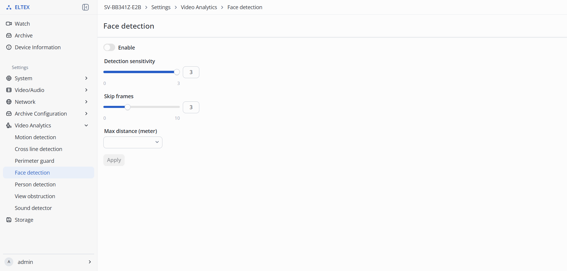
- Enable — enable/disable video analytics for Face detection;
- Detection sensitivity — parameter that controls the sensitivity of face detection. Sensitivity values range from 0 to 3; the higher the value, the smaller the objects that will be detected;
- Skip frames — parameter that determines how many intermediate frames the algorithm skips between scene analysis points. During scene analysis, every n frame will be used, where n can range from 0 to 10;
- Max distance (meter) — maximum distance at which face detection will work; this parameter is specified in meters.
To save the settings, click the "Apply" button.
"Person detection"
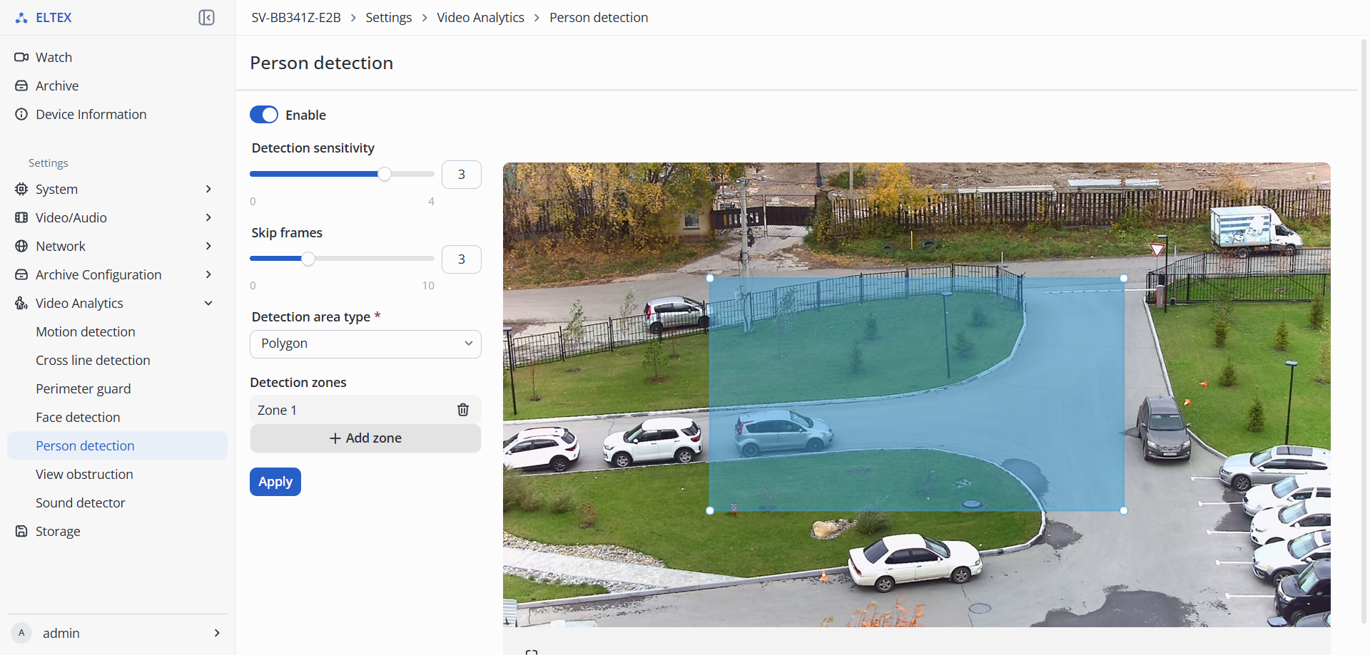
- Person detection:
- Enable — enable/disable video analytics for Person detection
- Detection sensitivity — parameter that controls the sensitivity of person detection. Sensitivity values range from 0 to 4; the higher the value, the smaller the objects that will be detected.
- Skip frames — parameter that determines how many intermediate frames the algorithm skips between scene analysis points. During scene analysis, every n frame will be used, where n can range from 0 to 10.
- Detection area type:
- Polygon — type of detection area consisting of an arbitrary polygon;
- Rectangle — type of detection area consisting of arbitrary rectangles.
- Full screen — detection area that covers the entire screen.
To save the settings, click the "Apply" button.
"View obstruction" menu
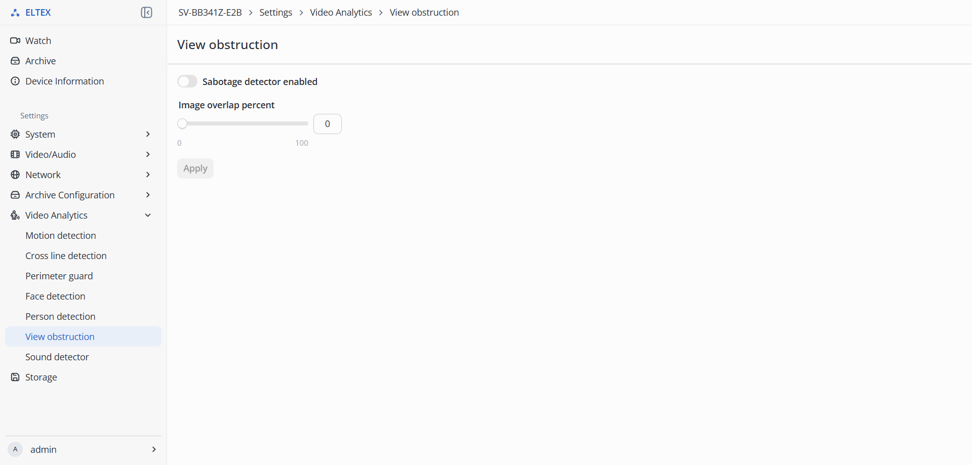
- Sabotage detector enabled — enable/disable video analytics for View obstruction;
- Image overlap percent — the higher the value, the greater the overlap between images required for a view obstruction to be detected.
"Sound detector" menu
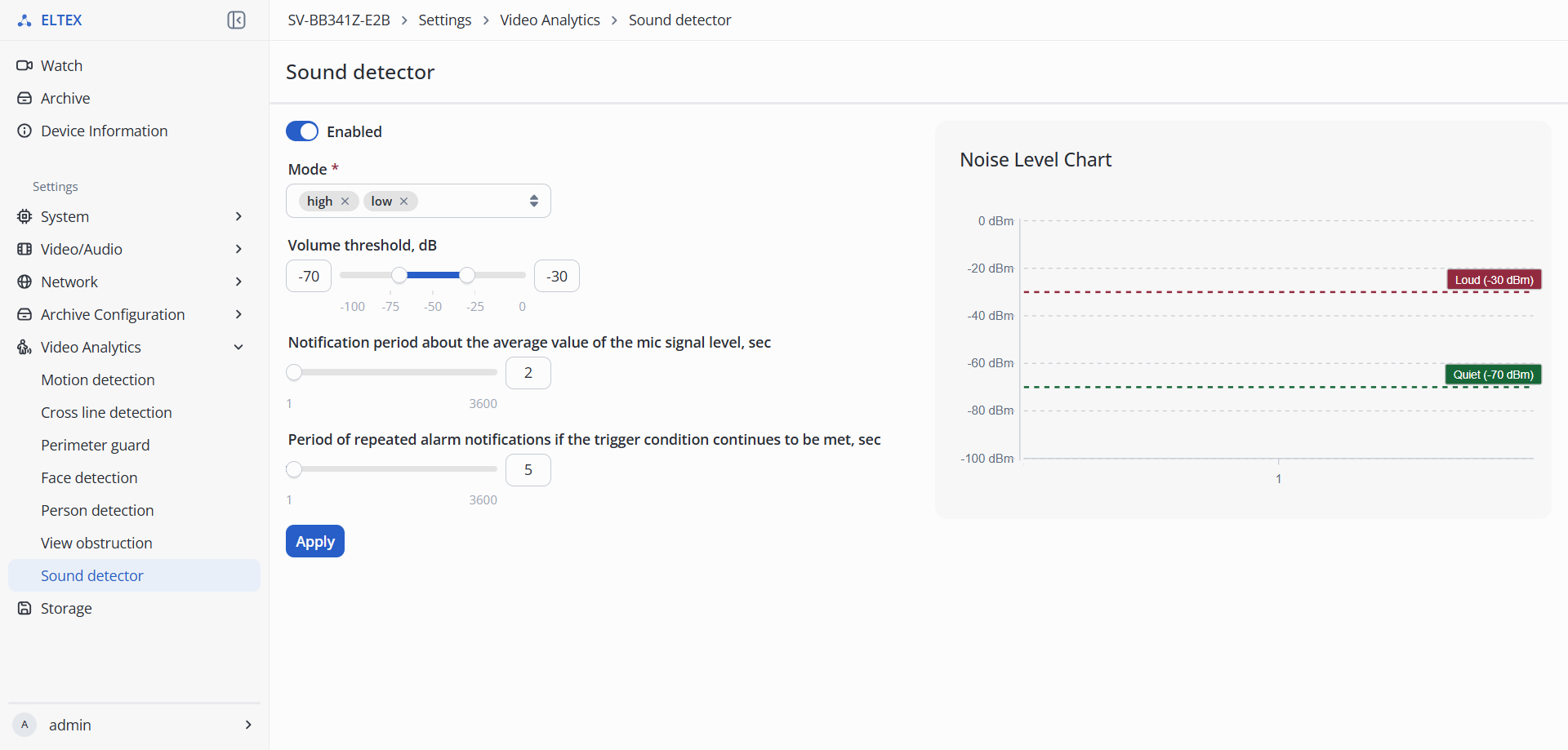
- Enabled — enable/disable video analytics for Sound detector;
- Mode — sound detection mode based on upper and lower thresholds:
- low — lower noise threshold;
- high — upper noise threshold.
- Volume threshold, dB — ability to set the upper and lower noise level thresholds using a slider;
- Notification period about the average value of the mic signal level, sec — frequency of notifications regarding the average microphone signal level;
- Period of repeated alarm notifications if the trigger condition continues to be met, sec — frequency of notifications if the trigger condition continues to be met.
"Storage Settings" menu
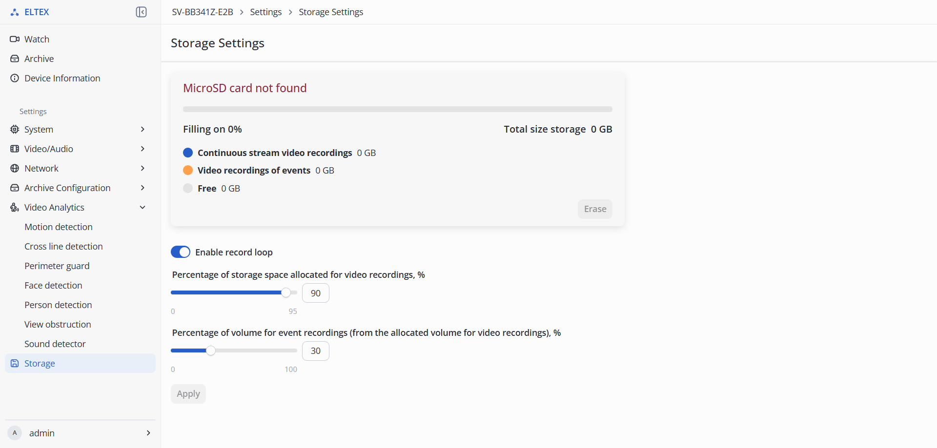
- Erase — formatting the MicroSD card for archive recording;
- Enable record loop — when the storage is full, old recordings will be overwritten with new ones.
- Percentage of storage space allocated for video recordings, % — indicates what part of the total storage volume will be used for storing video. It is possible to set a value in the range from 0 to 100;
- Percentage of volume for event recordings (from the allocated volume for video recordings), % — indicates how much space from this volume will be allocated for event recordings. It is possible to set a value in the range from 0 to 100.
When recording two streams with different recording modes, the storage volume is divided according to the set parameters. |
To save the settings, click the "Apply" button.