
Initial data
According to the technical specification, it is required to determine the hardware platform.
Table 1. Recommended hardware solutions
Requirements for SSW servers | Hardware Product Series | ||||
|---|---|---|---|---|---|
Light+ | Midi | Heavy | Super Heavy | Top (1) | |
System specifications | |||||
Maximum number of subscribers | 5000 | 10000 | 20000 | 40000 | - |
Maximum load of simultaneous connections class 5 | 800 | 1500 | 3000 | 6000 | - |
Maximum load of simultaneous connections class 4 | 2400 | 4500 | 9000 | 20000 | 80000 |
Server specifications | |||||
Model | HP (Lenovo) | HP (Lenovo) | HP (Lenovo) | HP (Lenovo) | HP / Lenovo / Depo |
Series | DL20 Gen10/DL 360 Gen10 (SR530) | DL360 Gen10 (SR530/SR630) | DL360 Gen10 (SR630) | DL360 Gen10 (SR630) | DL360 Gen10 / SR650 V2 / |
Processor | Intel Xeon 4214 | Intel Xeon 5220 | Intel Xeon 6240 | Intel Xeon 8268 | Intel Xeon 8380 |
Number of processors | 1 | 1 | 2 | 2 | 2 |
RAM | 16 GB | 24 GB | 32 GB | 64 GB | 1024 GB |
HDD | From 3X500 SATA | From 3x300 GB SAS | From 3x600 GB SAS | From 6x800 GB SSD, 2x300 GB M.2 SSD | From 6x1.2 TB SSD, 2x300 GB M.2 SSD |
RAID | No raid board | HW Raid, from 1 GB cache+battery | HW Raid, from 1 GB cache+battery | HW Raid, from 2 GB Flash cache, RAID-5 support | HW Raid, from 2 GB Flash cache, RAID-5 support |
Additional server components (not included in the basic set) | |||||
Remote management license | optional | + | + | + | + |
Redundant power supply | optional | + | + | + | + |
Storage of conversation records | Additional HDD combined in RAID-5 | HW Raid license with RAID-5 support, additional HDD for storing records | HW Raid license with RAID-5 support, additional HDD for storing records | HW Raid license with RAID-5 support, additional HDD for storing records | HW Raid license with RAID-5 support, additional HDD for storing records |
Data transmission network bandwidth
The required network bandwidth: no less than 1000 Mbps.
Table 2. Minimal requirements for installing ECSS-10 on virtual machines*
Requirements for SSW servers | Hardware Product Series | |||||
|---|---|---|---|---|---|---|
Light (2)(3) | Light+ | Midi | Heavy | Super Heavy | Top (1) | |
System specifications | ||||||
Maximum number of subscribers | 1000 | 5000 | 10000 | 20000 | 40000 | - |
Maximum load of simultaneous connections class 5 | 250 | 800 | 1500 | 3000 | 6000 | - |
Maximum load of simultaneous connections class 4 | 1000 | 4500 | 900 | 20000 | 80000 | - |
| Server specifications | ||||||
| Number of cores/threads (vCore) | 8C | 12С/24T | 18С/36T | 36С/72T | 48С/96T | 80С/160T and more |
CPU frequency | From 2.4 GHz | From 3 GHz | From 3 GHz | From 3.6 GHz | From 3.4 GHz | From 3.2 GHz |
RAM | 8 GB | 16 GB | 24 GB | 32 GB | from 64 GB | from 512 GB |
HDD | From 50 GB, 75 IOPS | From 500 GB SATA | From 500 GB SAS | From 500 GB SAS | From 800 GB SSD, 300 GB M.2 SSD | From 1.2 TB SSD, 300 GB M.2 SSD |
C — core;
T — thread, vCore;
(1) — Top series is intended for trunk gateway controller (class 4);
(2) — Light series is used for virtual machines calculations only. The minimum recommended series for hardware servers is Light+;
(3) — Light series is the minimum recommended series. It is used for calculations of virtual machines with minor subsciber number (under 1000: 100, 200);
*If it is planned to use services such as call center, call recording, and video calls, then it is necessary to coordinate the requirements with technical support.
Connecting to network
The topology of connecting the server to the network to ensure redundancy is recommended to be done using 2 switches.
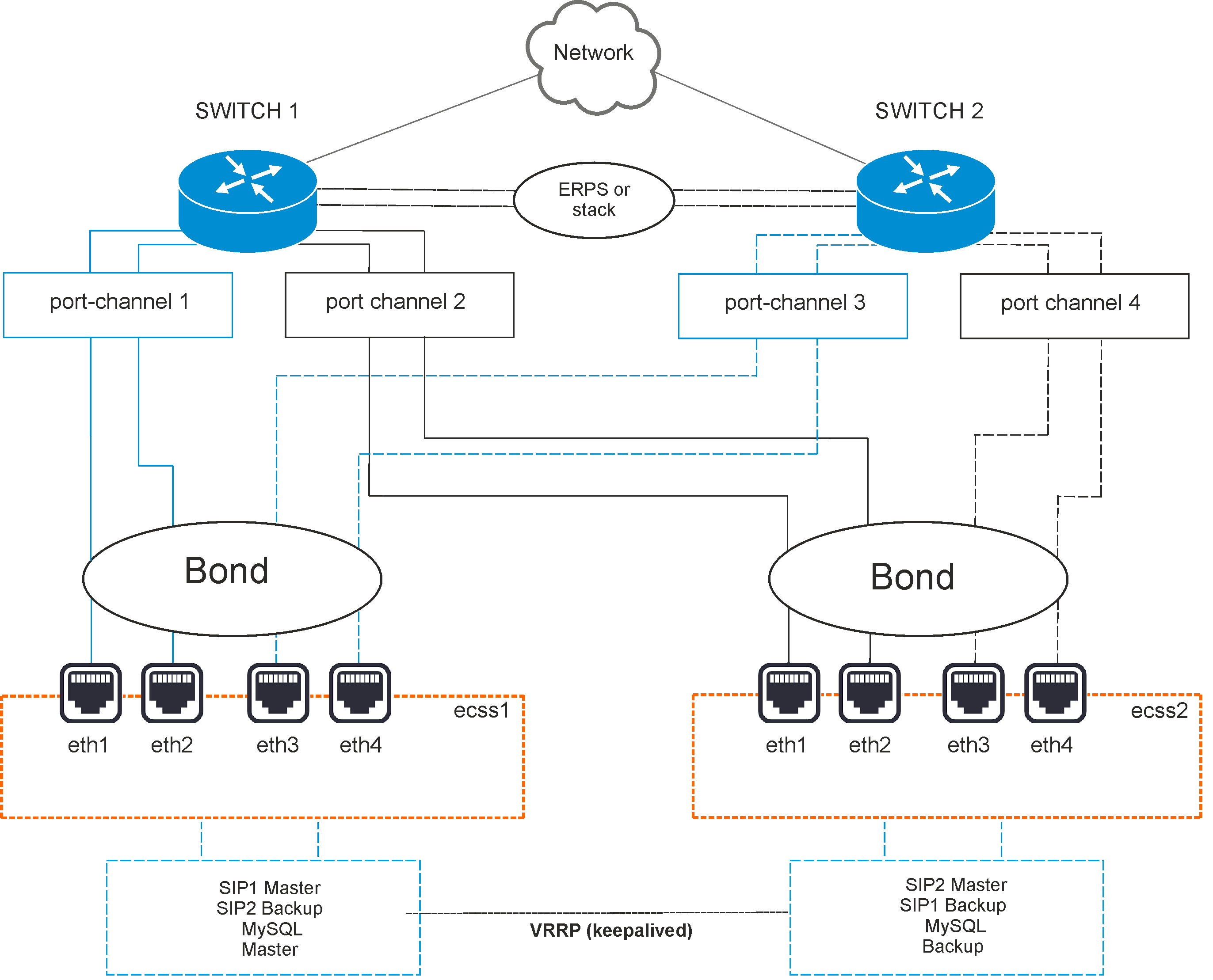
Figure 2 — Network connection diagram
Option 1. Active-backup
The switches are connected in erps ring.
All 4 physical network interfaces are connected into 1 aggregated link (bond). Server port aggregation is configured in active-backup mode, i.e. there is always only 1 network interface in operation. Server network interfaces are connected in pairs in switches, on which port aggregation (port-channel) is also configured in active-backup mode.
For example, eth0 and eth1 of each server are connected in the first switch (port-channel 1 and 2), and eth2 and eth3 (port-channel 3 and 4) are connected in the second one.
Option 2. LACP
The switches are connected in a stack. The stack must logically operate as a single switch, capable of providing port aggregation between different physical switches in LACP mode. MES-3124 with specialized firmware can be an example.
All 4 physical network interfaces are connected into 1 aggregated link (bond). Server port aggregation is configured in 802.3ad mode. Network cards aggregated groups with same rate and duplex are created. With such a combination, the transmission uses all channels in active aggregation according to the IEEE 802.3ad standard. The choice on which interface to send a packet is determined by policy. By default, it is XOR policy, also xmit_hash policy can be used. For more information, see Netplan section.
Requirements:
- Ethtool support in driver to obtain information about speed and duplex on each network interface;
- IEEE 802.3ad standard support on switch.
Server network interfaces are also connected in pairs in switches, on which port aggregation (port-channel) is configured in LACP mode. For example, eth0 and eth1 of each server are connected to first switch (port-channel 1), eth2 and eth3 are connected to the second one (port-channel 3 and 4).
Installation of ECSS-10 in a cluster of two servers
Installation of ECSS-10 consists of two main parts:
- Preparation: installation of Ubuntu 22.04, Ubuntu packets updating, OS "optimization", installation of additional software packages, preparation of network interfaces, /etc/hosts, ssh-keygen
- Installation of ECSS-10
Preparation
This section describes the operating system installation, as well as required and optional packages. ECSS-10 version 3.18 runs on Ubuntu 22.04.
Preliminary requirements:
- Installation media with the operating system distribution;
- A prepared server with an updated BIOS, ILO (if available), and a connected network for internet access;
- Setting the installation media (USB flash drive or CD/DVD) as the first boot priority in the BIOS;
- Sufficient disk space and memory as specified in the design.
OS installation
To install the OS, do the following:
- After booting from the installation media, select "Install Ubuntu Server"
- Select the system language and keyboard layout
- Configure the network interface to connect to the Internet
- Create disk partitions according to Table 1
- Configure server and user names
- Install OpenSSH server
- Reboot the successfully installed OS
Table1 — An option for storing information in a file system on physical media for servers
| 1 | Operating system boot partition (created automatically) | boot | raid 1: hdd1, hdd2 | boot | /boot | ext4 | 1 GB | Primary |
| 2 | Operating system root partition | root | raid 1: hdd1, hdd2 | root | / | ext4 | 30 GB | Logical |
| 3 | Local database information | mnesia | raid 1: hdd1, hdd2 | mnesia | /var/lib/ecss | ext4 | 10 GB | Logical |
| 4 | Distributed database for storing media resources | glusterfs | raid 1: hdd1, hdd2 или hdd3 | glusterfs | /var/lib/ecss/glusterfs* | ext4 | Max GB | Logical |
| 5 | OS subsystem operation logs | log | raid 1: hdd1, hdd2 или hdd3 | log | /var/log | ext4 | 20 GB | Logical |
| 6 | ECSS subsystem operation logs | ecss_log | raid 1: hdd1, hdd2 или hdd3 | ecss_log | /var/log/ecss | ext4 | 20 GB | Logical |
| 7 | Databases | ecss_db | raid 1: hdd1, hdd2 или hdd3 | ecss_db | /srv/ecss/ecss-postgres-bdr-ssw/ | ext4 | 100–400 GB** | Logical |
| 8 | User files | home | raid 1: hdd1, hdd2 или hdd3 | home | /home | ext4 | 10 GB | Logical |
* If the server will not work in a cluster, then a partition /var/lib/ecss/restfs is created instead of glusterfs.
** The recommended value for series Light, Light+, Midi is 100 GB. The recommended value for series Heavy is 200 GB, for Super Heavy is 400 GB.
The system requires at least 256 GB of free space.
It is neccessary to configure "hostname" parameter on the system servers.
It is recommended to specify the same username (anything except ssw) on all servers in the system. The ECSS-10 license is linked to the eToken/ruToken key and the computer hostname. The system user ssw is created when installing the ecss-user package.
When installing the system in a cluster, the recommended value for the first server is ecss1, for the second – ecss2.
Configuring network
Install the software switch according to the parameters specified in the technical specification. In this example, it is assumed that the required operating system is already installed.
It is recommended to split traffic used for different purposes. For example, management traffic and VoIP traffic. To do this, 2 or more VLANs are created. In the minimum case and with a small load, one VLAN can be enough. Hovewer, it will cause inconvenience in the future at traffic dump and its analysis. According to the technical specification, host IP addresses, gateways, DNS, routing in other networks are configured on VLAN.
According to the technical specification, the following addresses are used in a given example (in brackets are differences for ecss2):
- 10.0.10.11(12)/24 — for management, VLAN 10;
- 10.0.20.21(22)/24 — core, VLAN 20;
- 10.0.20.31(32)/24 — virtual addresses (vrrp) for VoIP;
- 10.0.10.10 — virtual address (vrrp) for MySQL server;
- 10.0.10.1 — gateway and dns for access to external network;
- 10.0.20.1 — gateway to 10.0.3.0/24 subnet;
- 10.136.16.211, 10.136.16.212 — NTP server addresses, which are accessed via 10.0.10.1 gateway.
There is an address structure inside the server platform and internal addresses are used for interaction between subsystems (nodes) in the cluster. For example, the internal address for a cluster on one server is 10.0.20.51, while the core (ecss-core) interacts with the multimedia data processing server (ecss-media-server). Their interaction takes place using the same address, but each software part has its own transport port: ecss-core — 5000, ecss-msr — 5040.
A single address for accessing the MySQL database is defined for all cluster nodes, for example, the ecss-mysql address 10.0.10.10. Thus, the uniformity condition is fulfilled, in which all cluster nodes have completely identical data about the current state of the dynamic components of the software switch (for example, call history).
First, the network interfaces are configured. In Ubuntu 22, the netplan utility is used for configuration:
sudo nano /etc/netplan/ecss_netplan.yaml |
In the configurations for each host, the ethernets section is declared first, which describes the existing ethernet interfaces in the system that will be used in the future. It is important for each interface to disable the use of dynamic address allocation (DHCP).
The next section describes aggregated channels — bonds. Depending on chosen network connection option, 1:1 (active - backup) or LACP (802.3ad) backup mode is configured.
Then, VLANs are configured, on which gateways for communication with the outside world and DNS server addresses are defined optionally, as well as IP addresses for each interface.
IMPORTANT
Note that while editing netplan, it is necessary to follow the YAML markup rules:
- Mandatory presence of two spaces before each line (except network).
- Each subsection is additionally shifted by 2 spaces:
→ Section |network
→ Subsection |_'_'bonds:
→ Subsection of the bonds section description |_'_'_'_'bonded_one:
→ etc. |_'_'_'_'...
- There is no space before the ":" sign, after — one space.
- Before the "-" sign, the number of spaces is as if a new subsection begins, after — one space.
Example of netplan for active-backup mode
| Netplan for ecss1 server interfaces (/etc/netplan/ecss_netplan.yaml) | Netplan for ecss2 server interfaces (/etc/netplan/ecss_netplan.yaml) |
|---|---|
# Netplan for the ecss1 host of the software switch
# Pay attention to the mandatory presence of at least two spaces in each line and section (except for the network section line)

network:
  version: 2 # netplan version
  renderer: networkd # netplan configuration executor
  ethernets: # Ethernet interfaces description section
    eth0: # Interface name
      dhcp4: no # Disabling dynamic distribution of IP address on the interfaces
    eth1:
      dhcp4: no
    eth2:
      dhcp4: no
    eth3:
      dhcp4: no

  bonds: # Section describing bonding interfaces.
    bond1: # Bonding interface name
      interfaces: # Section of determining bonding interfaces
		- eth0
		- eth1
		- eth2
		- eth3
      parameters: # Section of defining bonding interface parameters
        primary-reselect-policy: failure # allows for avoiding unnecessary switching.
        gratuitous-arp: 5 # Promotes faster switching
        all-slaves-active: true # accept incoming frames on backup interfaces
        up-delay: 1000 # make a delay of one second
        mode:  active-backup # Backup mode, one active and the rest are backup
        mii-monitor-interval: 100 # interface monitoring interval(ms)
        primary: eth0 # Main interface definition section
      optional: false # Determine whether an interface is required at startup

  vlans:
    net.10: # Management interface
      id: 10
        link: bond1
        addresses: [10.0.10.51/24]
        gateway4: 10.0.10.1 # Gateway address
        nameservers:
          addresses: [10.0.10.1, 8.8.8.8] # DNS servers addresses
        routes: # Routing for NTP subnet
          - to: 10.136.16.0/24
            via: 10.0.10.1 # Gateway address for this subnet
            on-link: true # Determines that the specified routes are directly associated with the interface
    net.20: # Interface for VoIP
        id: 20
        link: bond1
        addresses: [10.0.20.51/24]
        routes:
          - to: 10.0.3.0/24
            via: 10.0.20.1
            on-link: true
| # Netplan for the ecss2 host of the software switch
# Pay attention to the mandatory presence of at least two spaces in each line and section (except for the network section line)
network:
version: 2 # netplan version
renderer: networkd # netplan configuration executor
ethernets: # Ethernet interfaces description section
eth0: # Interface name
dhcp4: no # Disabling dynamic distribution of IP address on the intefaces
eth1:
dhcp4: no
eth2:
dhcp4: no
eth3:
dhcp4: no
bonds: # Section describing bonding interfaces.
bond1: # Bonding interface name
interfaces: # Section of determining bonding interfaces
- eth0
- eth1
- eth2
- eth3
parameters: # Section of defining bonding interface parameters
primary-reselect-policy: failure # allows for avoiding unnecessary switching.
gratuitous-arp: 5 # Promotes faster switching
all-slaves-active: true # accept incoming frames on backup interfaces
up-delay: 1000 # make a delay of one second
mode: active-backup # Backup mode, one active and the rest are backup
mii-monitor-interval: 100 # interface monitoring interval(ms)
primary: eth0 # Main interface definition section
optional: false # Determine whether an interface is required at startup
vlans:
net.10: # Management interface
id: 10
link: bond1
addresses: [10.0.10.52/24]
gateway4: 10.0.10.1 # Gateway address
nameservers:
addresses: [10.0.10.1, 8.8.8.8] # DNS servers addresses
routes: # Routing for NTP subnet
- to: 10.136.16.0/24
via: 10.0.10.1 # Gateway address for this subnet
on-link: true # Determines that the specified routes are directly associated with the interface
net.20: # Interface for VoIP
id: 20
link: bond1
addresses: [10.0.20.52/24]
routes:
- to: 10.0.3.0/24
via: 10.0.20.1
on-link: true
|
The following bond settings are required for the ECSS server to run correctly:
mode: active-backup - specifies the operating mode in which one link is selected as active, while the others remain in backup;
primary-reselect-policy: failure - specifies that a new active link should be selected only when the current active link fails. This avoids unnecessary switching;
gratuitous-arp: 5 - when the active link changes, five gratuitous ARP requests are sent to the switch to update its switching table. This facilitates faster switching;
all-slaves-active: true - forces incoming frames to be accepted on the backup interfaces. This ensures that traffic balancing on the MES does not interfere with operation. Data flows to the server from all links, and the server sends data only from the active link;
mii-monitor-interval: 100 - enables link monitoring via the MII interface and specifies a polling interval of 100 ms;
up-delay: 1000 - specifies that a connected interface should not be considered immediately available for operation, but rather a one-second delay should be applied after the interface has been connected. This is necessary to avoid unnecessary switching when the port repeatedly switches between the "on" and "off" states.
Example of netplan for 802.3ad mode
| Netplan for ecss1 server interfaces (/etc/netplan/ecss_netplan.yaml) | Netplan for ecss2 server interfaces (/etc/netplan/ecss_netplan.yaml) |
|---|---|
# Netplan for the ecss1 host of the software switch
# Pay attention to the mandatory presence of at least two spaces in each line and section (except for the network section line)

network:
  version: 2 # netplan version
  renderer: networkd # netplan configuration executor
  ethernets: # Ethernet interfaces description section
    eth0: # Interface name
      dhcp4: no # Disabling dynamic distribution of IP address on the interfaces
    eth1:
      dhcp4: no
    eth2:
      dhcp4: no
    eth3:
      dhcp4: no

  bonds: # Section describing bonding interfaces.
    bond1: # Bonding interface name
      interfaces: # Section of determining bonding interfaces
		- eth0
		- eth1
		- eth2
		- eth3
      parameters: # Section of defining bonding interface parameters
        mode: 802.3ad # LACP mode
        mii-monitor-interval: 100 # Section of interface monitoring (ms)
        primary: eth0 # Section of determining main interface
      optional: false # Determining if an interface is required at startup

  vlans:
    net.10: # Management interface
      id: 10
        link: bond1
        addresses: [10.0.10.51/24]
        gateway4: 10.0.10.1 # Gateway address
        nameservers:
          addresses: [10.0.10.1, 8.8.8.8] # DNS servers addresses
        routes: # Routing for NTP subnet
          - to: 10.136.16.0/24
            via: 10.0.10.1 # Gateway address for this subnet
            on-link: true # Determines that the specified routes are directly associated with the interface
    net.20: # Interface for VoIP
        id: 20
        link: bond1
        addresses: [10.0.20.51/24]
        routes:
          - to: 10.0.3.0/24
            via: 10.0.20.1
            on-link: true
| # Netplan for the ecss2 host of the software switch
# Pay attention to the mandatory presence of at least two spaces in each line and section (except for the network section line)
network:
version: 2 # netplan version
renderer: networkd # netplan configuration executor
ethernets: # Ethernet interfaces description section
eth0: # Interface name
dhcp4: no # Disabling dynamic distribution of IP address on the interfaces
eth1:
dhcp4: no
eth2:
dhcp4: no
eth3:
dhcp4: no
bonds: # Section describing bonding interfaces.
bond1: # Bonding interface name
interfaces: # Section of determining bonding interfaces
- eth0
- eth1
- eth2
- eth3
parameters: # Section of defining bonding interface parameters
mode: 802.3ad # LACP mode
mii-monitor-interval: 100 # Section of interface monitoring (ms)
primary: eth0 # Section of determining main interface
optional: false # Determining if an interface is required at startup
vlans:
net.10: # Management interface
id: 10
link: bond1
addresses: [10.0.10.52/24]
gateway4: 10.0.10.1 # Gateway address
nameservers:
addresses: [10.0.10.1, 8.8.8.8] # DNS servers addresses
routes: # Routing for NTP subnet
- to: 10.136.16.0/24
via: 10.0.10.1 # Gateway address for this subnet
on-link: true # Determines that the specified routes are directly associated with the interface
net.20: # Interface for VoIP
id: 20
link: bond1
addresses: [10.0.20.52/24]
routes:
- to: 10.0.3.0/24
via: 10.0.20.1
on-link: true
|
It is also recommended to check for any other files in the /etc/netplan/ directory. If other files are present, they should be moved to another directory or deleted. Otherwise, incorrect configuration of network interfaces and incorrect operation of SSW may occur.
Apply parameters with the command:
sudo netplan apply |
You can view the resulting settings using the ifconfig or ip a commands.
It is neccessary to configure "hostname" parameter on the system servers.
It is recommended to specify the same username (anything except ssw) on all servers in the system. The ECSS-10 license is linked to the eToken/ruToken key and the computer hostname. The system user ssw is created when installing the ecss-user package.
When installing the system in a cluster, the recommended value for the first server is ecss1, for the second – ecss2.
Other host names are possible only upon project approval; this will be required to generate licenses.
Specify hostname: ecss1 / ecss2 in file /etc/hostname:
sudo nano /etc/hostname
Configuring /etc/hosts
After configuring netplan, specify that the internal address 10.0.10.Х belongs to the corresponding ecssX server. To do this, configure /etc/hosts.
| Configuring hosts for ecss1 (/etc/hosts) | Configuring hosts for ecss2 (/etc/hosts) |
|---|---|
127.0.0.1 localhost # Local loop address, used by some ecss services 10.0.10.51 ecss1 # Host address | 127.0.0.1 localhost # Local loop address, used by some ecss services 10.0.10.52 ecss2 # Host address |
Now, if you call the ping utility on ecssX, you can contact the neighboring server:
| Accessing ecss2 from ecss1 | Accessing ecss1 from ecss2 |
|---|---|
ping ecss2 PING ecss2 (10.0.10.52) 56(84) bytes of data. 64 bytes from ecss2 (10.0.10.52): icmp_seq=1 ttl=64 time=0.047 ms | ping ecss1 PING ecss1 (10.0.10.51) 56(84) bytes of data. 64 bytes from ecss1 (10.0.10.51): icmp_seq=1 ttl=64 time=0.032 ms |
Next, one should organize access between servers via ssh using RSA keys - without using a password.
Generate an RSA key with the following command (execute the command without sudo so that the key is generated for the current user), when executing the command three questions will be asked, you can use the default value by pressing Enter three times:
ssh-keygen
ssh-copy-id ecss2
The same way on ecss2.
ssh-copy-id ecss1
Check the connection between the servers. From the ecss1 server side - ssh ecss2, the connection should be established without asking for a password. Similarly, from the ecss2 server side - ssh ecss1.
Optimization of the operating system
Set OS settings to performance mode
Use cpufrequtils utility.
sudo apt install -y cpufrequtils
By default, after installation, Ubuntu uses the "ondemand" mode (CPU performance is based on application requests, saving power, but lower performance):
cat /etc/init.d/cpufrequtils | grep GOVERNOR=
In the system output message, the default operating mode after installation is "ondemand":
GOVERNOR="ondemand"
Set the efficiency/performance mode - replace the value "ondemand" with "performance" in the file /etc/init.d/cpufrequtils.
sudo sed -i 's/GOVERNOR="ondemand"/GOVERNOR="performance"/g' /etc/init.d/cpufrequtils
Restart the utility:
sudo /etc/init.d/cpufrequtils restart
Then run the command:
sudo systemctl daemon-reload
Disable SWAP
The Ubuntu SSW server operates in real time, so all necessary data must be in RAM. Using a swap file (/swap.img) can increase the processing time of ECSS10 SSW application calls, which is unacceptable. Disable swap.
Run three commands in sequence:
Disable swap:
sudo swapoff -a
Delete swap.img file.
sudo rm /swap.img
Comment out the line "/swap.img none swap sw 0 0" in the "/etc/fstab" file – change it to "# /swap.img none swap sw 0 0"
or delete this line (/swap.img none swap sw 0 0).
sudo nano /etc/fstab
# /etc/fstab: static file system information.
#
# Use 'blkid' to print the universally unique identifier for a
# device; this may be used with UUID= as a more robust way to name devices
# that works even if disks are added and removed. See fstab(5).
#
# <file system> <mount point> <type> <options> <dump> <pass>
# / was on /dev/sda2 during curtin installation
/dev/disk/by-uuid/731728e2-4d6b-499a-afea-9362fd6726b2 / ext4 defaults 0 1
# /swap.img none swap sw 0 0
To check, run the command free -h:
free -h
Swap size is 0 – that is, it is disabled
free -h
              total        used        free      shared  buff/cache   available
Mem:           3,9G        110M        3,2G        820K        535M        3,5G
Swap:            0B          0B          0B
Setting the time zone
When installing Ubuntu 22, it is not prompted to set a time zone (UTC is the default). One should set it manually (for the rating system, scheduled tasks, etc.) to function correctly. For example:
sudo timedatectl set-timezone Asia/Novosibirsk
If system components are moved to different servers/VMs (ecss-node/ecss-msr), it is necessary to specify a single time zone for all system components.
Improving the performance of high-load servers
It is possible to improve the performance of high-load servers by increasing the open file limit.
To set the open file limit, follow these steps:
Check the current limit with the command:
ulimit -a
Result:
eltex@ecss1:~$ ulimit -a
core file size          (blocks, -c) 0
data seg size           (kbytes, -d) unlimited
scheduling priority             (-e) 0
file size               (blocks, -f) unlimited
pending signals                 (-i) 15515
max locked memory       (kbytes, -l) 65536
max memory size         (kbytes, -m) unlimited
open files                      (-n) 1024
pipe size            (512 bytes, -p) 8
POSIX message queues     (bytes, -q) 819200
real-time priority              (-r) 0
stack size              (kbytes, -s) 8192
cpu time               (seconds, -t) unlimited
max user processes              (-u) 15515
virtual memory          (kbytes, -v) unlimited
file locks                      (-x) unlimited
This limit (open files 1024) is not enough for normal operation of high-load servers.
Set open file limit for each user:
sudo sed -i '55i\* soft nproc 65536\n* hard nproc 131072\n* soft nofile 65536\n* hard nofile 131072\nroot - memlock unlimited' /etc/security/limits.conf
IMPORTANT
Installation of packages must be done NOT under the ssw system user.
Operating system software update
To install the ECSS-10 system, add the ELTEX repository:
sudo sh -c "echo 'deb [arch=amd64] http://archive.eltex.org/ssw/jammy/3.18 stable main extras external' > /etc/apt/sources.list.d/eltex-ecss10-stable.list"
Next, import the key with the following command:
sudo apt-key adv --keyserver keyserver.ubuntu.com --recv-keys 33CB2B750F8BB6A5
To update the OS, run the following commands:
sudo apt update
In case the following system message is displayed
W: http://archive.eltex.org/ssw/jammy/3.18/dists/unstable/InRelease: Key is stored in legacy trusted.gpg keyring (/etc/apt/trusted.gpg), see the DEPRECATION section in apt-key(8) for details.
Run the following command:
sudo cp /etc/apt/trusted.gpg /etc/apt/trusted.gpg.d
sudo apt upgrade
Software installation and configuration
установка пакетов deb
┌ ECSS software version. Currently, it is listed as version 3 in the certification application.
  | It is not changed until the next certification or
  │ the release of a fundamentally new version of the system.
  │
  │     ┌ System Release Version. This is the common version for all components included in a specific release.
  |     | It is changed centrally
  │     │ when decided to launch a new release. Releases are usually not compatible with each other.
┌─┴┐ ┌──┴─┐
ECSS.SysRel.SubMaj.SubMin
            └──┬─┘ └──┬─┘
               │      └ Subsystem minor version. The minor version of a subsystem is set by the subsystem developer.
               |        The minor version
               │        is changed when a patch is added. Minor versions within a single major version are generally
               │        compatible with each other and differ within specific patches.
               │
               └ Subsystem major version. The major version is set by the subsystem developer.
The major version of a subsystem must be updated when significant changes are made to the subsystem.The APT package installation utility analyzes package version from left to right. For example, if we have package 14.14.7.7, the repository contains packages:
14.14.7.8
14.14.7.9
14.14.8.1
14.14.20–14.14.28.
Then, when running the sudo apt install package name command → package 14.14.28 will be automatically checked and installed. Since it is the most recent, the analysis will be performed based on the third position (major), and the fourth position (minor) will not be analyzed (the same applies to sudo apt upgrade command).
If a specific situation requires upgrading from version 14.14.7.7 to version 14.14.7.9, the standard command → sudo apt upgrade will not help, since the newest package will be selected. In this situation, it is needed to explicitly specify which version of the package wanted to be installed. In this example, we should select the command → sudo apt install package name=14.14.7.9. This is usually necessary for testing a specific patch; for standard updates, it is enough to select the usual command to install/update the package.
Install all the proposed packages:
sudo apt install -y ntp ntpdate tcpdump vlan dnsmasq aptitude atop ethtool htop iotop mc minicom mtr-tiny nmap pptpd pv screen ssh tftpd vim sngrep tshark cpanminus gnuplot libgraph-easy-perl debconf-utils
Also install packages for system with redundancy:
sudo apt install -y ifenslave keepalived attr
Before installing the ecss packages, it is needed to ensure that the network's bandwidth meets the requirements.
To do this, run the command sudo ethtool <interface name> for all physical interfaces.
Check the following:
- Advertised auto-negotiation: Yes
- Speed: 1000 Mbps (minimum)
- Duplex: Full
Installing the mandatory ECSS package
Installing the ecss-dns-env package
To install, run the command:
sudo apt install -y ecss-dns-env
The setup wizard will prompt to select sections for configuration based on the questions below. You need to select a broker (for example, 10.0.10.51 and 10.0.10.52).
| Questions ecss-dns-env | Replies for ecss1 | Ответы for ecss2 |
|---|---|---|
| [Primary broker] enter address ([Primary broker] Enter IP) | 10.0.10.51 (required) | 10.0.10.51 (required) |
| [Secondary broker] enter address ([Secondary broker] Enter IP) | 10.0.10.52 (required) | 10.0.10.52 (required) |
IMPORTANT
In case of subsequent correction of IP addresses, the following command should be used:
sudo dpkg-reconfigure ecss-dns-env
Installing Postgres
Note
Before installing ecss-postgres-bdr-ssw, docker must be added to the apt sources on the system. To do this, run the following commands:
sudo install -m 0755 -d /etc/apt/keyrings
sudo curl -fsSL https://download.docker.com/linux/ubuntu/gpg -o /etc/apt/keyrings/docker.asc
sudo chmod a+r /etc/apt/keyrings/docker.asc
echo \
  "deb [arch=$(dpkg --print-architecture) signed-by=/etc/apt/keyrings/docker.asc] https://download.docker.com/linux/ubuntu \
  $(. /etc/os-release && echo "${UBUNTU_CODENAME:-$VERSION_CODENAME}") stable" | \
  sudo tee /etc/apt/sources.list.d/docker.list > /dev/null
sudo apt update && sudo apt upgrade
Installing ecss-postgres-bdr-ssw package
Performed sequentially, first installed on the server running in "Master" mode.
sudo apt install -y ecss-postgres-bdr-ssw
When installing the ecss-postgres-bdr-ssw package, the following questions will be asked:
| Questions ecss-postgres-bdr-ssw | Replies for ecss1 (Master) |
|---|---|
| Current IP address of the network interface. | Select an IP address from the list to use with Postgres |
| Installing in a cluster? | Yes (default value) |
| Is this node a master node? | Yes (required) |
sudo apt install -y ecss-postgres-bdr-ssw
When installing the ecss-postgres-bdr-ssw package, the following questions will be asked:
| Questions ecss-postgres-bdr-ssw | Replies for ecss2 (Slave) |
|---|---|
| Current IP address of the network interface. | Select an IP address from the list to use with Postgres |
| Installing in a cluster? | Yes (default value) |
| Is this node a master node? | Yes (required) |
| IP address used to connect to the cluster: | Specify the IP address of the Master (ecss1) |
Check that the replication settings are correct
When installing, the script postgresbdr_ssw.sh is installed in /srv/ecss/ecss-postgres-bdr-ssw directory.
To check replication, run the following commands:
cd /srv/ecss/ecss-postgres-bdr-ssw
sudo ./postgresbdr_ssw.sh check
The output on the hosts should be the same:
sudo ./postgresbdr_ssw.sh checkEnter master ip pleaseLike 10.150.150.1510.0.10.51Enter slave ip please10.0.10.52Press enter with empty passwordПросто щелкайте Enter не вводя парольq - выход из просмотра таблицы (если необходимо)таблица нод на мастере по ecss_storekeeper_dbтаблица нод на слейве по ecss_storekeeper_dbтаблица коннекций на мастер по ecss_storekeeper_db conn_sysid | conn_dsn ---------------------+--------------------------------------------------------------------------------------- 7569499877813944343 | host=10.0.10.51 port=5439 dbname=ecss_storekeeper_db user=postgres password=postgres1 7569514001040228374 | host=10.0.10.52 port=5439 dbname=ecss_storekeeper_db user=postgres password=postgres1(2 rows)
таблица коннекций на слейве по ecss_storekeeper_db conn_sysid | conn_dsn ---------------------+--------------------------------------------------------------------------------------- 7569499877813944343 | host=10.0.10.51 port=5439 dbname=ecss_storekeeper_db user=postgres password=postgres1 7569514001040228374 | host=10.0.10.52 port=5439 dbname=ecss_storekeeper_db user=postgres password=postgres1(2 rows)
sudo ./postgresbdr_ssw.sh checkEnter master ip pleaseLike 10.150.150.1510.0.10.51Enter slave ip please10.0.10.52Press enter with empty passwordПросто щелкайте Enter не вводя парольq - выход из просмотра таблицы (если необходимо)таблица нод на мастере по ecss_storekeeper_dbтаблица нод на слейве по ecss_storekeeper_dbтаблица коннекций на мастер по ecss_storekeeper_db conn_sysid | conn_dsn ---------------------+--------------------------------------------------------------------------------------- 7569499877813944343 | host=10.0.10.51 port=5439 dbname=ecss_storekeeper_db user=postgres password=postgres1 7569514001040228374 | host=10.0.10.52 port=5439 dbname=ecss_storekeeper_db user=postgres password=postgres1(2 rows)
таблица коннекций на слейве по ecss_storekeeper_db conn_sysid | conn_dsn ---------------------+--------------------------------------------------------------------------------------- 7569499877813944343 | host=10.0.10.51 port=5439 dbname=ecss_storekeeper_db user=postgres password=postgres1 7569514001040228374 | host=10.0.10.52 port=5439 dbname=ecss_storekeeper_db user=postgres password=postgres1(2 rows)
Installing ecss-node
Installation of the required ecss-node package includes installation and initial configuration of the main subsystems.
The ecss-postgres-bdr-ssw package should already be installed on the system.
To install the ecss-node package, run the command:
sudo apt install -y ecss-node
During package installation, the ssw user is created, under which all ecss* services are launched. The necessary directories are created, DNS is configured, and SSL certificates are configured.
During installation, the ecss-user package will also be installed.
Installing on ecss1 server
During installation, it will be prompted to configure the parameters necessary for generating configuration files. Examples of replies are below.
| ecss-user questions | Replies for ecss1 | Пример |
|---|---|---|
| Хотите ли вы использовать стандартные настройки? | Yes (значение по умолчанию) |
|
| Вопросы ecss-node | Ответы для ecss1 | Пример |
Идентификатор ECSS-узла в формате DNS (Настройка имени кластера): (любое уникальное имя, в примере abf.test) | abf.test (необходимо ввести) Формат ECSS_ID [A-Za-z0-9][A-Za-z0-9.-][A-Za-z0-9] |
|
| Хотите ли вы использовать стандартные настройки? | No (необходимо выбрать) |
|
| Выберите пункты, которые хотите настроить: | ntp + cookie (необходимо выбрать) |
|
| Внешние NTP серверы через пробел: | ntp.ubuntu.com (значение по умолчанию) |
|
| NTP: Вы хотите использовать настройки для кластера? | Yes (значение по умолчанию) |
|
| NTP: Установка Startum для кластера: | 7 (значение по умолчанию) |
|
| NTP укажите локальне серверы для синхронизации через пробел: (в примере ecss2 - 10.0.10.52) | 10.0.10.52 (необходимо ввести) |
|
| NTP: Вы хотите определить сети вручную, у которых должен быть доступ до ntp? | Yes (значение по умолчанию) |
|
| NTP: Сети у которых должен быть доступ до ntp через пробел: (в примере 10.0.10.0|255.255.255.0 10.0.20.0|255.255.255.0) | 10.0.10.0|255.255.255.0 10.0.20.0|255.255.255.0 (необходимо ввести) |
|
Cookie для ноды core: (указать уникальный cookie для core , в примере ecss-core-example ) В кластерной конфигурации cooke должны быть одинаковые для нод одного типа
| ecss-core-example (необходимо ввести) |
|
Cookie для ноды ds: (указать уникальный cookie для ds , в примере ecss-ds-example ) В кластерной конфигурации cooke должны быть одинаковые для нод одного типа | ecss-ds-example (необходимо ввести) |
|
Cookie для ноды mediator: (указать уникальный cookie для mediator , в примере ecss-mediator-example ) В кластерной конфигурации cooke должны быть одинаковые для нод одного типа | ecss-mediator-example (необходимо ввести) |
|
Cookie для ноды pa-sip: (указать уникальный cookie для pa-sip , в примере ecss-pa-sip-example) В кластерной конфигурации cooke должны быть одинаковые для нод одного типа | ecss-pa-sip-example (необходимо ввести) |
|
Cookie для ноды mycelium: (указать уникальный cookie для mycelium , в примере ecss-mycelium-example) В кластерной конфигурации cooke должны быть одинаковые для нод одного типа | ecss-mycelium-example (необходимо ввести) |
|
Cookie для ноды sorm: (указать уникальный cookie для sorm , в примере ecss-sorm-example) В кластерной конфигурации cooke должны быть одинаковые для нод одного типа | ecss-sorm-example (необходимо ввести) |
|
| Вопросы ecss-user | Ответы для ecss1 | Пример |
| Максимальный размер несжатого дампа в байтах. | 8G (значение по умолчанию) |
|
| Максимальный размер сжатого дампа в байтах. | 2G (значение по умолчанию) |
|
| Максимальный размер, который может занять каталог /var/lib/systemd/coredump: | default (значение по умолчанию) |
|
| Минимальный объем свободного дискового пространства в байтах. | 30G (значение по умолчанию) |
|
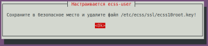
Сохраните в безопасное место и удалите файл /etc/ecss/ssl/ecss10root.key! | Ok (значение по умолчанию) |
|
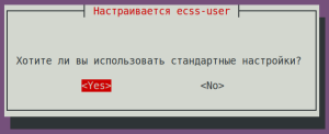
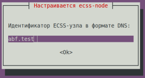
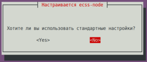
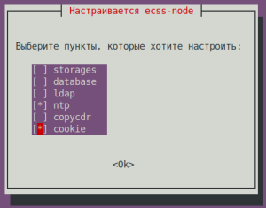
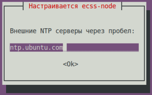
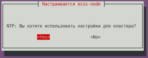
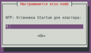
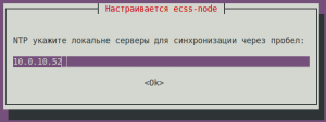
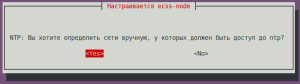
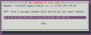
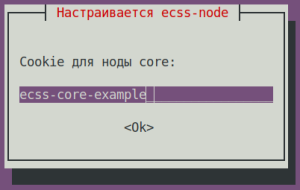
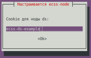
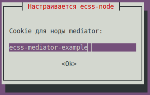
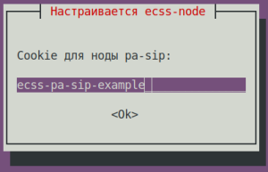
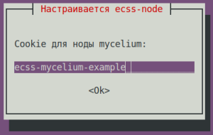
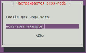
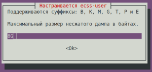
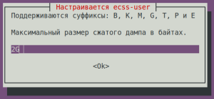

000000000000000000000
Configuring the ecss-mysql package
During installation, the customizer will ask questions, replies are given in the table below. Note that the password is the same for both hosts on which mysql is installed.
| Questions | Replies for ecss1 | Replies for ecss2 |
|---|---|---|
| Address mask for MySQL (IP pattern for MySQL permission) | 192.168.1.% | 192.168.1.% |
| User login (Login for MySQL root) | root | root |
| MySQL user password (Password for MySQL root) | PASSWORD | PASSWORD |
Changing the default path — agree to change the configuration file to enter the path to the ecss-mysql databases by entering "Y".
mysql databases used by the ECSS-10 system will be stored under the path /var/lib/ecss-mysql after installation. Check for files in the folder:
ls -l /var/lib/ecss-mysql/
total 36
drwxr-xr-x 2 mysql mysql 4096 Sep 26 13:36 ecss_address_book
drwxr-xr-x 2 mysql mysql 4096 Sep 26 13:37 ecss_audit
drwxr-xr-x 2 mysql mysql 4096 Sep 26 13:36 ecss_calls_db
drwxr-xr-x 2 mysql mysql 4096 Sep 26 13:36 ecss_dialer_db
drwxr-xr-x 2 mysql mysql 4096 Sep 26 13:36 ecss_meeting_db
drwxr-xr-x 2 mysql mysql 4096 Sep 26 13:36 ecss_statistics
drwxr-xr-x 2 mysql mysql 4096 Sep 26 13:36 ecss_subscribers
drwxr-xr-x 2 mysql mysql 4096 Sep 26 13:36 history_db
drwxr-xr-x 2 mysql mysql 4096 Sep 26 14:32 web_conf
Check that the server is running:
systemctl status mysql.service

● mysql.service - MySQL Community Server
   Loaded: loaded (/lib/systemd/system/mysql.service; enabled; vendor preset: enabled)
  Drop-In: /etc/systemd/system/mysql.service.d
           └─override.conf
   Active: active (running) since Sun 2022-02-06 15:25:15 +07; 3 days ago
  Process: 3766 ExecStart=/usr/sbin/mysqld --daemonize --pid-file=/run/mysqld/mysqld.pid (code=exited, status=0/SUCCESS)
  Process: 3736 ExecStartPre=/usr/share/mysql/mysql-systemd-start pre (code=exited, status=0/SUCCESS)
 Main PID: 3783 (mysqld)
    specifications: 87 (limit: 4915)
   CGroup: /system.slice/mysql.service
           └─3783 /usr/sbin/mysqld --daemonize --pid-file=/run/mysqld/mysqld.pid
Next, support access between servers with ecss-mysql via ssh using rsa keys without password use.
On the ecss1 host, generate rsa key with the following command (run the command without sudo so that the key is generated for the current user):
ssh-keygen
ssh-copy-id tester@ecss2
Generate rsa key on the ecss2 host the same way, replacing the host part with ecss1.
ssh-keygen
ssh-copy-id tester@ecss1
Next, run the mysql database replication script on ecss1:
sudo /usr/lib/ecss/ecss-scripts/mysql-replication/install_replication.sh
Before executing the script, define certain parameters. Example of reply to the questions for different hosts are listed below. Note that the PASSWORD password is the same password that was set above.
| Questions | Replies for ecss1 |
|---|---|
| Login for access to database | root |
| Password for access to database | PASSWORD |
| Login for the replication user | replica |
| Password for the replication user | replica |
| Address of the first host | 10.0.10.11 |
| Address of the second host | 10.0.10.12 |
| Name of the second host | ecss2 |
| Username on the second host | tester |
| Mediator IP | 127.0.0.1 |
| SNMP port | 162 |
| Create keepalived configuration | yes |
After the script is running, you can check that replica@192.168.1 .% and replica@% user has been created in MySQL on both hosts:
mysql -uroot -ppassword
mysql> SELECT user,host FROM mysql.user;
Among all users, you can see such an entry:
+------------------+---------------+
|           user   |      host     |
+------------------+---------------+
| replica          |192.168.1.%    |
+------------------+---------------+
Checking replica status:
sudo mysql -uroot -p -e 'show slave status \G;' | grep -E "Slave_IO_Running:|Slave_SQL_Running:"
Enter password:
Slave_IO_Running: Yes
Slave_SQL_Running: Yes
Editing keepalived.conf
Next step is to edit global configuration file keepalived.conf. The contents are the same on both hosts.
sudo nano /etc/keepalived/keepalived.conf
global_defs {
    vrrp_version 3          # VRRP protocol version (2 or 3)
    script_user nobody      # system user with limited rights, from which accessibility check scripts will be launched
    enable_script_security  # do not run scripts as root if part of the path to them is writable for normal users
}

include /etc/keepalived/sip.conf
include /etc/keepalived/mysql.conf
Since automatic configuration generation for mysql was involved, then in the configuration file there will be only a link to ecss-mysql-replication.conf:
include /etc/keepalived/mysql.conf
Then /etc/keepalived/mysql.conf are created on both hosts.
Creating VRRP for MySQL
| /etc/keepalived/mysql.conf for ecss1 | /etc/keepalived/mysql.conf for ecss2 |
|---|---|
# Configuring mysql for first node:

vrrp_script check_mysql {
    script "/usr/bin/mysql --defaults-file=/etc/mysql/debian.cnf -e 'SELECT 1;'"
    user root
    interval 2
    fall 1
    timeout 2
}

vrrp_instance MySQL {
    state MASTER                     # Initial state at start
    interface net.10                 # Name of the network interface, on which VRRP will operate
    virtual_router_id 10             # Unique router id (0..255)
    priority 100                     # Priority (0..255) the higher the more
    advert_int 1                     # Notification sending interval (sec)
    preempt_delay 60                 # Master wait interval at daemon start (sec) at BACKUP initial state

    unicast_src_ip  10.0.10.11       # Own real IP address
    unicast_peer {
         10.0.10.12                  # Neighbour real IP address
    }

    virtual_ipaddress {
        # Virtual IP address and a mask
        # dev - network interface on which virtual address will operate
        # label - virtual interface label (for ease of identification)
        10.0.10.10/24 dev net.10 label net.10:mysql
   }

    track_script {
        check_mysql
    }
} | # Configuring mysql for the second node:
vrrp_script check_mysql {
script "/usr/bin/mysql --defaults-file=/etc/mysql/debian.cnf -e 'SELECT 1;'"
user root
interval 2
fall 1
timeout 2
}
vrrp_instance MySQL {
state MASTER # Initial state at start
interface net.10 # Name of the network interface, on which VRRP will operate
virtual_router_id 10 # Unique router id (0..255)
priority 50 # Priority (0..255) the higher the more
advert_int 1 # Notification sending interval (sec)
preempt_delay 60 # Master wait interval at daemon start (sec) at BACKUP initial state
unicast_src_ip 10.0.10.12 # Own real IP address
unicast_peer {
10.0.10.12 # Neighbour real IP address
}
virtual_ipaddress {
# Virtual IP address and a mask
# dev - network interface on which virtual address will operate
# label - virtual interface label (for ease of identification)
10.0.10.10/24 dev net.10 label net.10:mysql
}
track_script {
check_mysql
}
} |
In this configuration, the ID for the virtual router is set, which will be the balancer for its host. It is important that virtual_router_id matches for both hosts.
After checking, restart the keepalived service:
sudo systemctl restart keepalived.service |
By calling ifconfig after reboot, you can see that the vlan2:mysql interface has appeared on one of the hosts.
ifconfig |
Installing the ecss-node package
Installing the ecss-node package:
sudo apt install ecss-node
During installation, you will be prompted to configure some parameters, an example of replies follows below.
For more information about configuring NTP, see "Time synchronization on servers".
| Questions | Replies for ecss1 | Replies for ecss2 |
|---|---|---|
| Do you want turn off apt-daily update? | Yes | Yes |
| Set DB config to default? | Yes | Yes |
| Set alarm true when MYSQL DB overloads? | Yes | Yes |
| NTP: Do you want use settings for cluster? | Yes | Yes |
| NTP: Set stratum for cluster | 7 | 7 |
| External NTP servers through a space | 10.136.16.211 10.136.16.212 | |
| NTP: Do you want to use other servers for time synchronization? | Yes | Yes |
| NTP: Indicate local servers for synchronization separated a space: | 10.0.10.12 | 10.0.10.11 |
| NTP: Addresses and Masks of Network, which must have access to the ntp through a space | Enter list of subnets from which access from this NTP server will be, eg: 10.0.10.0|255.255.255.0 | |
| NTP: Do you want to define manually which networks should have access to ntp? | Yes | Yes |
NTP: Networks that should have access to ntp separated by space: Format: <network address>|mask (x.x.x.x|255.255.255.0) | 10.0.10.0|255.255.255.0 | 10.0.10.0|255.255.255.0 |
| Install utilities for working with cdr | No | No |
Select manual mode for certificates generation. All questions can be answered with default answers by clicking "Enter" for all questions.
Installing and configuring the remaining ecss packages
Next, install all the necessary packages on both hosts (for more information on installing necessary and additional packages, see "Installation of ECSS packages"):
sudo apt install ecss-media-server ecss-media-resources ecss-web-conf ecss-restfs
To write media server (ecss-media-server / MSR) initial configuration parameters to the configuration file, configure transport-port, transport bind-addr, mcc bind-addres, and mcc bind-port:
| Questions for ecss-media-server | Replies for ecss1 | Replies for ecss2 |
|---|---|---|
| Enter port (Enter) | 5040 | 5040 |
| Enter bind-ip address(Enter) | 10.0.20.11 | 10.0.20.12 |
| Enter the control channel address (bind-addr) | 10.0.20.11 | 10.0.20.12 |
| Enter the control channel port | 5700 | 5700 |
Select configuration mode (Choose config mode) | auto | auto |
| Set default settings: | yes | yes |
| Enter name (Enter) | msr.ecss1 | msr.ecss2 |
| Enter address (Entrer) | 10.0.20.11 | 10.0.20.12 |
| Enter port (Entrer) | 5000 | 5000 |
After forming default configurations, go to the directory where the configurations are located and check them:
cd /etc/ecss/ecss-media-server/ |
There is a configuration for msr: config.xml, the conf.d directory contains the configuration default.xml. At its core, default.xml is an addition to config.xml, which defines the accounts section. This is done in order for this configuration to remain unchanged after package updates.
Example of config.xml:
<?xml version="1.0" encoding="utf-8"?>
<config date="10:48:15 21.02.2022">
  <general log-level="3" log-rotate="yes" max-calls="8192" max-in-group="512" load-sensor="media" load-delta="10" calls-delta="100" spool-dir-size="100M" log-name="msr.log" log-path="/var/log/ecss/media-server" use-srtp="disabled" suspicious-mode="no"/>
  <transport bind-addr="10.0.20.11" port="5040" transport="udp+tcp"/>
  <!-- By default configured public TURN-server -->
  <turn-server use-turn="no" host="numb.viagenie.ca" user="webrtc@live.com" password="muazkh"/>
  <media mixer-clock-rate="8000" use-vad="no" cng-level="0" jb-size="60" rtcp-timeout="0" rtp-timeout="350" udp-src-check="no" cn-multiplier="3" port-start="12000" port-range="2048" tias-in-sdp="no" thread-cnt="2" silence-threshold="-30" dtmf-flash-disable="no" video-dscp="0" other-dscp="0" dummy-video-src="/usr/share/ecss-media-server/video/dummy_video.yuv" video-enc-width="1280" video-enc-height="720" finalsilence="1000" rtcp-stat-dump="yes"/>
  <codec pcma="1" pcmu="2" ilbc="0" gsm="0" g722="3" g729="0" speex="0" l16="0" g7221="0" opus="0" h264="1" h263-1998="2" t38="1" tel-event-pt="0"/>
  <accounts>
    <!-- <dynamic msr_name="msr.name"
            realm="sip:127.0.0.1:5000"
            dtmf_mode="rfc+inband+info"
            auth_name="user"
            auth_password="password" /> -->
  </accounts>
  <pbyte>
    <mcc bind-addr="10.0.20.11" port="5700"/>
  </pbyte>
  <conf_dir path="/etc/ecss/ecss-media-server/conf.d"/>
  <rtp>
    <auto addr-v4=""/>
  </rtp>
</config>
Example of accounts section (default.xml file):
| Configuring msr for ecss1 (/etc/ecss/ecss-media-server/conf.d/default.xml) | Configuring msr for ecss2 (/etc/ecss/ecss-media-server/conf.d/default.xml) |
|---|---|
<?xml version="1.0"?>
<config>
      <accounts>
            <dynamic msr_name="msr.ecss1" realm="sip:10.0.20.11:5000" dtmf_mode="rfc+inband+info" auth_name="user" auth_password="password"/>
            <dynamic msr_name="msr.ecss1" realm="sip:10.0.20.12:5000" dtmf_mode="rfc+inband+info" auth_name="user" auth_password="password"/>
      </accounts>
</config>
| <?xml version="1.0"?>
<config>
<accounts>
<dynamic msr_name="msr.ecss2" realm="sip:10.0.20.11:5000" dtmf_mode="rfc+inband+info" auth_name="user" auth_password="password"/>
<dynamic msr_name="msr.ecss2" realm="sip:10.0.20.12:5000" dtmf_mode="rfc+inband+info" auth_name="user" auth_password="password"/>
</accounts>
</config>
|
It contains current settings according to which the msr is registered on core.
The main parameters are: msr_name and realm.
- msr_name is a parameter that defines the name of the msr. (it is recommended to set the name of the msr. and the host to which it belongs, for example, msr.ecss1);
- realm — defines the address for registration on the core. Default entry point: port 5000.
Configuring VRRP for SIP adapter
To configure VRRP for SIP adapter, create on both servers files, the view of which is shown below:
sudo nano /etc/keepalived/sip.conf |
| etc/keepalived/sip.conf для ecss1 | etc/keepalived/sip.conf для ecss2 |
|---|---|
vrrp_script check_sip {
script "/usr/bin/ecss_pa_sip_port 65535"
interval 2
timeout 2
}
# Configuring address for the first SIP adapter virtual address
vrrp_instance SIP1 {
state MASTER # Initial state at start
interface net.20 # Name of the network interface, on which VRRP will operate
virtual_router_id 31 # Unique router id (0..255)
priority 100 # Priority (0..255) the higher the more
advert_int 1 # Notification sending interval (sec)
preempt_delay 60 # Master wait interval at daemon start (sec) at BACKUP initial state
unicast_src_ip 10.0.20.11 # Own real IP address
unicast_peer {
10.0.20.12 # Neighbour real IP address
}
virtual_ipaddress {
# Virtual IP address and a mask
# dev - network interface on which virtual address will operate
# label - virtual interface label (for ease of identification)
10.0.10.31/24 dev net.20 label net.20:SIP1
} | vrrp_script check_sip {
script "/usr/bin/ecss_pa_sip_port 65535"
interval 2
timeout 2
}
# Configuring address for the first SIP adapter virtual address
vrrp_instance SIP1 {
state BACKUP # Initial state at start
interface net.20 # Name of the network interface, on which VRRP will operate
virtual_router_id 31 # Unique router id (0..255)
priority 50 # Priority (0..255) the higher the more
advert_int 1 # Notification sending interval (sec)
preempt_delay 60 # Master wait interval at daemon start (sec) at BACKUP initial state
unicast_src_ip 10.0.20.12 # Own real IP address
unicast_peer {
10.0.10.11 # Neighbour real IP address
}
virtual_ipaddress {
# Virtual IP address and a mask
# dev - network interface on which virtual address will operate
# label - virtual interface label (for ease of identification)
10.0.20.31/24 dev net.20 label net.20:SIP1
} |
In this case, support for virtual interfaces with Master-Backup communication has been added. For ecss1, the main interface is net.20:SIP1, and the backup is net.20:SIP2, respectively. It is important to note that the configuration takes into account the use of address variables. In the interface section, specify on which interface VRRP messages will be listened to, and specify the interface on which the virtual address will be restored in the virtual_ipaddress section.
Restart keepalived:
sudo systemctl restart keepalived.service |
Further configuring of the software switch
mycelium.config
Cluster name is set in the ecss-mycelium /etc/ecss/ecss-mycelium/mycelium.config package configuration:
sudo nano /etc/ecss/ecss- mycelium/mycelium1.config |
Perform configuring on both hosts.
| Configuring cluster name (/etc/ecss/ecss-mycelium/mycelium1.config) |
|---|
%%% -*- mode:erlang -*- |
epmd
Configuring epmd:
systemctl edit epmd.service |
Creating a new service and editing it:
| Configuring epmd ecss1 | Configuring epmd ecss2 |
|---|---|
[Service] Environment="ERL_EPMD_ADDRESS=127.0.1.1,192.168.1.1" | [Service] Environment="ERL_EPMD_ADDRESS=127.0.1.1,192.168.1.2" |
Restart services:
systemctl daemon-reload systemctl restart epmd.service |
glusterfs
Configure glusterfs for ecss-restfs on the first host (ecss1), to do this, install the glusterfs-server and attr packages on both hosts:
sudo aptitude install glusterfs-server attr |
After installation, create a connection with remote virtual host:
sudo gluster peer probe 192.168.1.2 |
Check the presence of the created connection:
sudo gluster peer status |
Next, create a cluster for replication, start replication and check its status:
sudo gluster volume create ecss_volume replica 2 transport tcp 192.168.1.1:/var/lib/ecss/glusterfs 192.168.1.2:/var/lib/ecss/glusterfs force |
Thus, the replication status will look as follows:
Volume Name: ecss_volume |
Mount glusterfs partition, for this purpose create a new service:
/etc/systemd/system/ecss-glusterfs-mount.service |
Add the following configuration to it:
| Configuring /etc/systemd/system/ecss-glusterfs-mount.service |
|---|
[Unit] Description=mount glusterfs After=network.target Requires=network.target [Service] RemainAfterExit=no Type=forking RestartSec=10s Restart=always ExecStart=/sbin/mount.glusterfs localhost:/ecss_volume /var/lib/ecss/restfs -o fetch-attempts=10 ExecStop=/bin/umount /var/lib/ecss/restfs [Install] WantedBy=multi-user.target |
Restart services:
sudo systemctl daemon-reload |
Check that the partition is mounted:
df -h <...> |
Configuring security. SSH
Configuring SSH server:
sudo nano /etc/ssh/sshd_config
In the configuration file, specify the port and address where you can access the server:
| Configuring ssh for ecss1(/etc/ssh/sshd_config) | Configuring ssh for ecss2 (/etc/ssh/sshd_config) |
|---|---|
# This is the sshd server system-wide configuration file. See # This sshd was compiled with PATH=/usr/bin:/bin:/usr/sbin:/sbin # The strategy used for options in the default sshd_config shipped with Port 2000 <...> | # This is the sshd server system-wide configuration file. See # This sshd was compiled with PATH=/usr/bin:/bin:/usr/sbin:/sbin # The strategy used for options in the default sshd_config shipped with Port 2000 <...> |
Restart ssh:
systemctl restart ssh.service
Configuring ecss-node package cluster
Start the necessary services:
IMPORTANT
Before starting work, check the presence of Token in the system.
Run the ecss-mycelium and ecss-ds packages on the first host:
sudo systemctl start ecss-mycelium
sudo systemctl start ecss-ds
Go to the CLI:
ssh admin@localhost -p 8023
password: password
Check system status:
admin@ds1@ecss1:/$ system-status
Checking...
┌─┬───────────────┬──────────────────────────┬───────────────┬─────────────┬──────┐
│ │     Node      │         Release          │ Erlang nodes  │Mnesia nodes │Uptime│
├─┼───────────────┼──────────────────────────┼───────────────┼─────────────┼──────┤
│ │ds1@ecss1      │ecss-ds-3.14.10.222       │ds1@ecss1      │ds1@ecss1    │0h 9m │
│ │mycelium1@ecss1│ecss-mycelium-3.14.10.222 │mycelium1@ecss1│not running  │0h 9m │
└─┴───────────────┴──────────────────────────┴───────────────┴─────────────┴──────┘
Next, upload your passport and licenses to the system:
cluster/storage/ds1/licence/set-passport <ssw passport>
ok
cluster/storage/ds1/licence/add <ssw licence>
ok
Exit and start the rest of the services on the first and second host.
ecss1:
sudo systemctl start ecss-core ecss-pa-sip ecss-mediator ecss-media-server ecss-restfs ecss-web-conf
ecss2:
sudo systemctl start ecss-mycelium ecss-ds ecss-core ecss-pa-sip ecss-mediator ecss-media-server ecss-restfs ecss-web-conf
Return to CLI:
ssh admin@localhost -p 8023
password: password
Next, connect the MSR- and Core-subsystems. To do this, use the following command:
admin@[mycelium1@ecss1]:/$ /system/media/resource/declare core1@ecss1 iface msr.ecss1 bond1_ecss1_pa default local true |
After all the services have started, the nodes will be establishing communication for some time. As soon as all nodes are loaded into system-status, the following information will be output:
admin@mycelium1@ecss1:/$ system-status
Checking...
┌─┬───────────────┬──────────────────────────┬───────────────────────────────┬───────────────────────────┬───────┐
│ │     Node      │         Release          │         Erlang nodes          │       Mnesia nodes        │Uptime │
├─┼───────────────┼──────────────────────────┼───────────────────────────────┼───────────────────────────┼───────┤
│ │core1@ecss1    │ecss-core-3.14.10.222     │core1@ecss1,core1@ecss2        │not running                │34m 28s│
│ │core1@ecss2    │ecss-core-3.14.10.222     │core1@ecss1,core1@ecss2        │not running                │6m     │
│ │ds1@ecss1      │ecss-ds-3.14.10.222       │ds1@ecss1,ds1@ecss2            │ds1@ecss1,ds1@ecss2        │34m 29s│
│ │ds1@ecss2      │ecss-ds-3.14.10.222       │ds1@ecss1,ds1@ecss2            │ds1@ecss1,ds1@ecss2        │6m     │
│ │md1@ecss1      │ecss-mediator-3.14.10.222 │md1@ecss1,md1@ecss2            │md1@ecss1,md1@ecss2        │33m 54s│
│ │md1@ecss2      │ecss-mediator-3.14.10.222 │md1@ecss1,md1@ecss2            │md1@ecss1,md1@ecss2        │6m     │
│ │mycelium1@ecss1│ecss-mycelium-3.14.10.222 │mycelium1@ecss1,mycelium1@ecss2│not running                │34m 49s│
│ │mycelium1@ecss2│ecss-mycelium-3.14.10.222 │mycelium1@ecss1,mycelium1@ecss2│not running                │6m     │
│ │sip1@ecss1     │ecss-pa-sip-3.14.10.222   │sip1@ecss1,sip1@ecss2          │sip1@ecss1,sip1@ecss2      │33m 54s│
│ │sip1@ecss2     │ecss-pa-sip-3.14.10.222   │sip1@ecss1,sip1@ecss2          │sip1@ecss1,sip1@ecss2      │6m     │
└─┴───────────────┴──────────────────────────┴───────────────────────────────┴───────────────────────────┴───────┘

All services are started.

  Active media resource selected list specific:
┌─────────────┬───────────┬────────────┬───────────┬───────────┐
│    Node     │  MSR      │    MSR     │ Cc-status │ Cc-uptime │
│             │           │  version   │           │           │
├─────────────┼───────────┼────────────┼───────────┼───────────┤
│ core1@ecss1 │ msr.ecss1 │ 3.14.10.67 │ connected │ 00:32:03  │
│             │ msr.ecss2 │ 3.14.10.67 │ connected │ 00:23:56  │
│ core1@ecss2 │ msr.ecss1 │ 3.14.10.67 │ connected │ 00:02:39  │
│             │ msr.ecss2 │ 3.14.10.67 │ connected │ 00:02:38  │
└─────────────┴───────────┴────────────┴───────────┴───────────┘
It can be seen that the nodes have entered the cluster and the MSR has registered on the ecss-core node.
Configuring group of IP addresses (IP-set)
Configure SIP adapter according to the technical specification:
/cluster/adapter/sip1/sip/network/set ip_set test_set node-ip node = sip1@ecss1 ip = 10.0.20.31
Property "ip_set" successfully changed from:
to
test_set: no ports set
test_set: sip1@ecss1 10.0.20.31
test_set: dscp 0.


cluster/adapter/sip1/sip/network/set ip_set test_set node-ip node = sip1@ecss2 ip = 10.0.20.32
Property "ip_set" successfully changed from:
to
test_set: no ports set
test_set: sip1@ecss1 10.0.20.31
test_set: sip1@ecss2 10.0.20.32
test_set: dscp 0.

/cluster/adapter/sip1/sip/network/set ip_set test_set listen-ports list = [5062]
Property "ip_set" successfully changed from:
ipset1:
ipset1: sip1@ecss1 10.0.20.31
ipset1: sip1@ecss2 10.0.20.32
ipset1: dscp 0
   to
ipset1: 5062
ipset1: sip1@ecss1 10.0.20.31
ipset1: sip1@ecss2 10.0.20.32
ipset1: dscp 0
Next, create a domain and assign to it the created group (IP-set) of the SIP adapter settings:
domain/declare test_domain --add-domain-admin-privileges --add-domain-user-privileges
New domain test_domain is declared


domain/test_domain/sip/network/set ip_set [test_set]

Property "ip_set" successfully changed from:

[] to ["test_set"].
After creating the domain, configure:
- routing;
- users;
- subscribers;
- trunks.
Example of a primary system configuration using web configurator
Initial data
- System installation is complete;
- System is ready for further configuring;
- Interfaces are running.
It is recommended to use the latest available browser versions. Recommended browsers: Opera, Chrome.
To start configuring the system, go to the web configurator.
To determine and register in the system, the following are planned:
- Subscribers with numbers 101, 102 , 103, 104 ,105, 106, 107, 108, 109, 110;
- Trunk towards the gateway.
Preparation for work
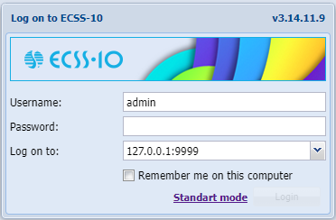
Figure 1 — Log in to the web configurator (authorization window)
In the authorization window, enter the values defined during the installation of the web configurator.
Default values for authorization:
Login: admin
Password: password
After logging in, the main workspace with application icons will be visible, as well as status bar with available options, in particular:
- 1 — log out of the system;
- 2 — domain selection;
- 3 — language selection.

Figure 2 —View of the web configurator workspace
Creating an operator account
After authorization, in order to increase security during the operation of the software switch, it is recommended to create accounts for operators, as well as to change the password for the admin user.
To create a new operator account, use User manager application:
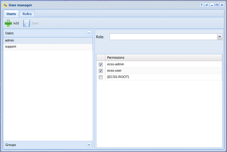
Figure 3 — Application view "User Manager"
Click the "Add" button  . In the window that opens, define a new account, for this:
- In the "Name" field, enter the login of the account, for example, "test";
- In the "Password" field and "Confirmation" field enter the password for the user, for example "testpassword";
- Define level of access rights for the user by selecting current permissions or using roles, for example ecss-user.
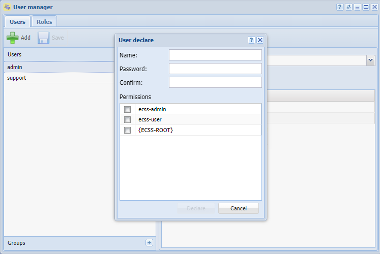
Figure 4 — Operator account creation dialog box
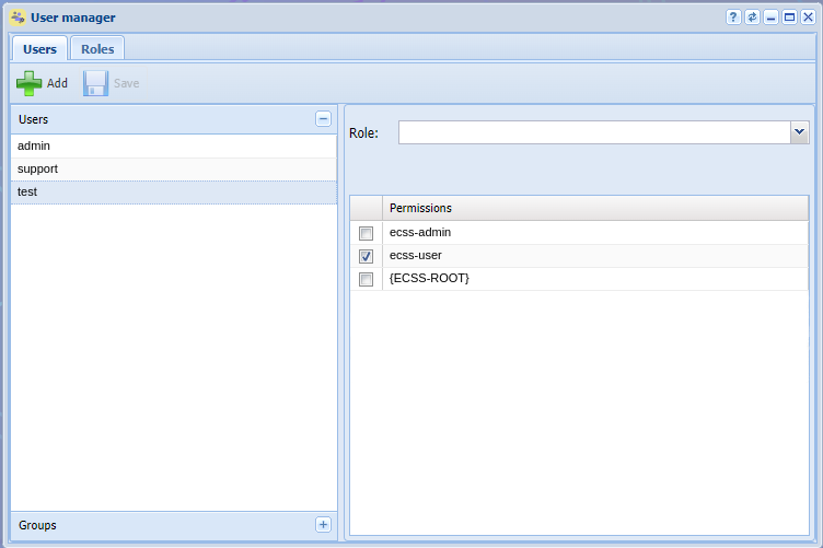
Figure 5 — Application view with created operator account
To change the password, click the edit button next to the user name. In the dialog box that opens, enter:
- Old password (for the admin user, the default password is password);
- New password;
- Confirm new password.
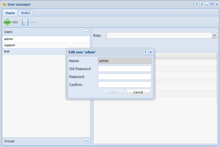
Figure 6 — Edit user dialog box
Creating a domain
To create a domain, log in to the Domains application. In the window that opens, create a domain, for this:
1. Click the Add domain button:
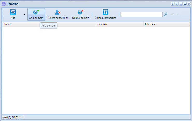
Figure 7 — Adding domain to the system
2. The following settings are available in the dialog box that opens:
- Name — individual name of the virtual PBX;
- Service profile (SS profile) — system profile of additional services. This profile will be copiedwith the same name to newly created domain and all services from this profile will be automatically allowed access via access-list;
- IVR profile (IVR profile) — the IVR profile specified in the IVR Constraints Editor application.
Enter the domain name, for example "test_domain";
3. Click Ok:
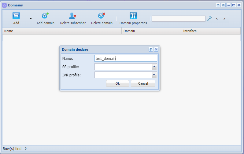
Figure 8 — Domain declare
4. Click the Update button.
Created domain will be displayed in the current configuration:
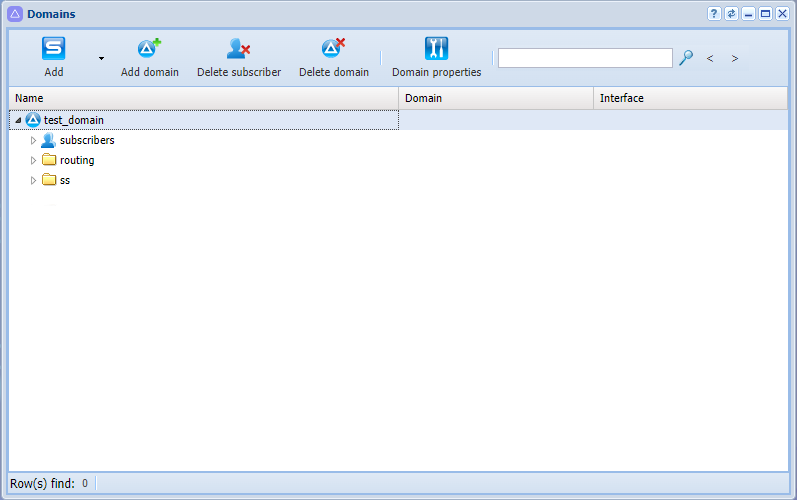
Figure 9 — Displaying created domain
To edit current domain, it must be selected in the system. To switch to a domain, use the domain selection option (see point 2 in the figure View of the web configurator workspace).
After selecting the domain, according to the current system configuration, all applications will be available:
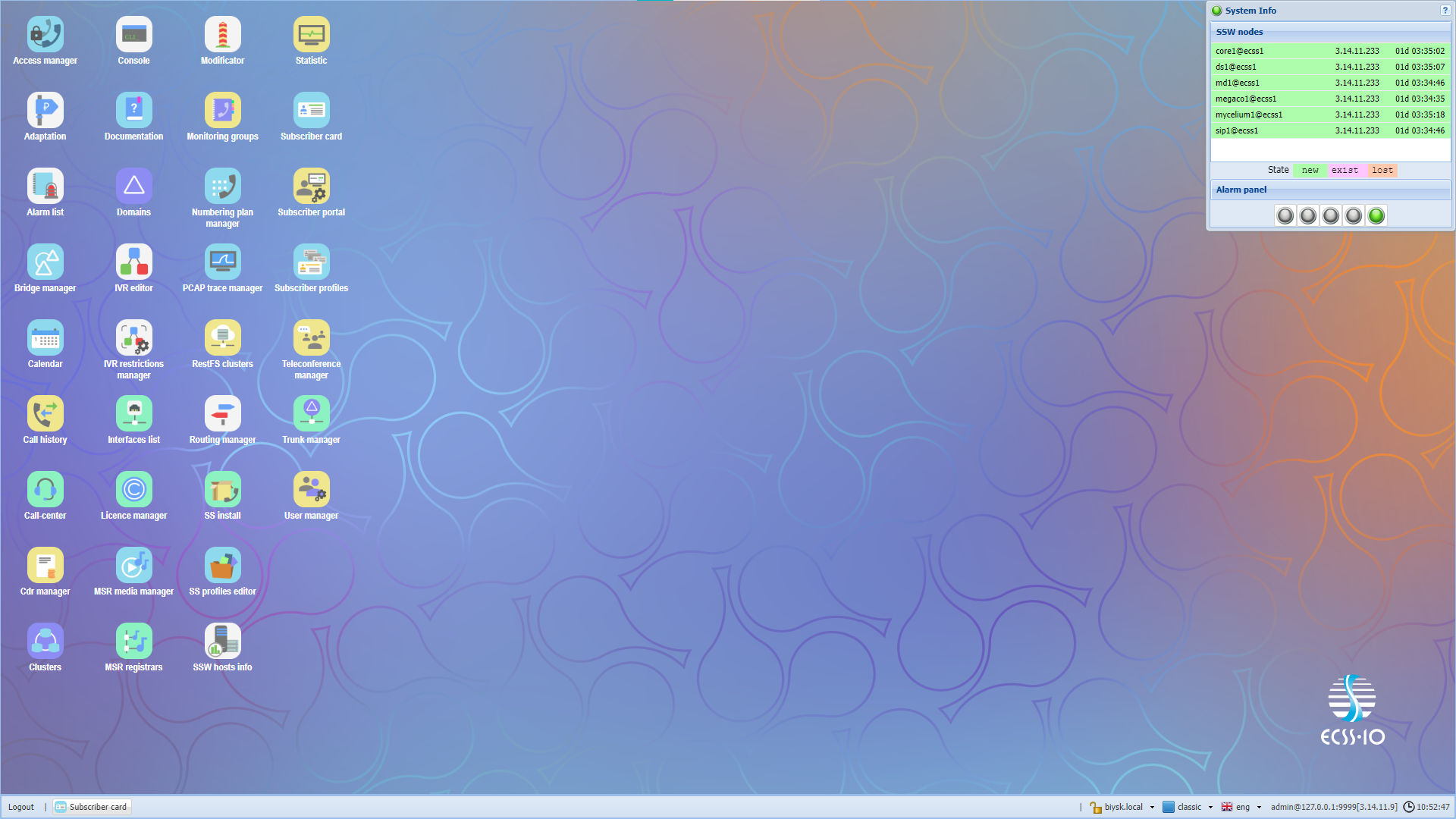
Figure 10 — Displaying applications in current system configuration
Creating IP-set (sip transport) and assigning it to a domain
To configure an interface, open the Clusters application.
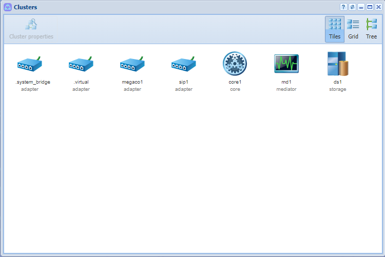
Figure 11 — Clusters application view
To create a new IP address group (IP-set), select the SIP adapter cluster "sip1" and click on the Cluster Properties button (or double-click on the cluster icon with left mouse button).
In the dialog box that appears, go to the Transport tab. Next, click on Add button. New group will appear. To edit the fields, double-click the one you need:
- Rename an address group (IP-set), for example "test_set";
- Specify the port on which the domain will be accessed, for example 5062;
- Expand newly created group by clicking on the triangle to the left of the group name;
- Define the address for the SIP adapter node, according to the configuration example:
For a system without redundancy, specify 10.0.3.238 and 10.0.3.241:
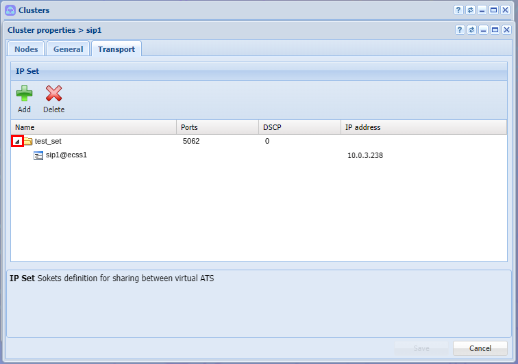
Figure 12 — Assigning an IP address in SIP adapter settings for a single adapter
For a redundant system, specify 10.0.3.238 and 10.0.3.241:
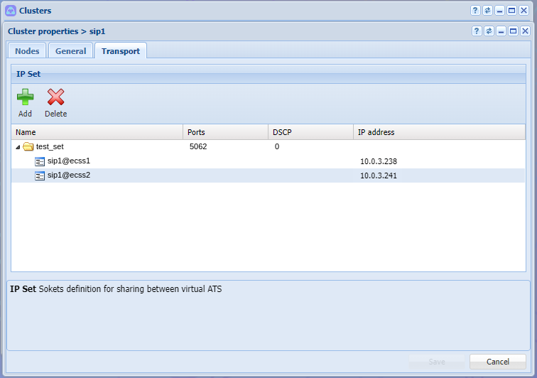
Figure 13 — Assigning a group of IP addresses in SIP adapter settings for two adapters, click Save to apply the settings.
In order to link a group of addresses to a domain, return to Domains application, select the domain and go to settings by clicking the Domain Properties or by double-clicking the left mouse button on the domain.
In the open list settings, open SIP branch, then SIP transport, and then select created group of addresses in IP set field. Click Save to apply the settings.
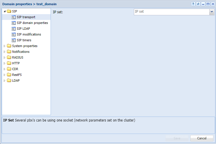
Figure 14 — Configuration window for SIP transport
Creating subscribers
The Subscriber card application is used to create and edit subscriber parameters in the system.
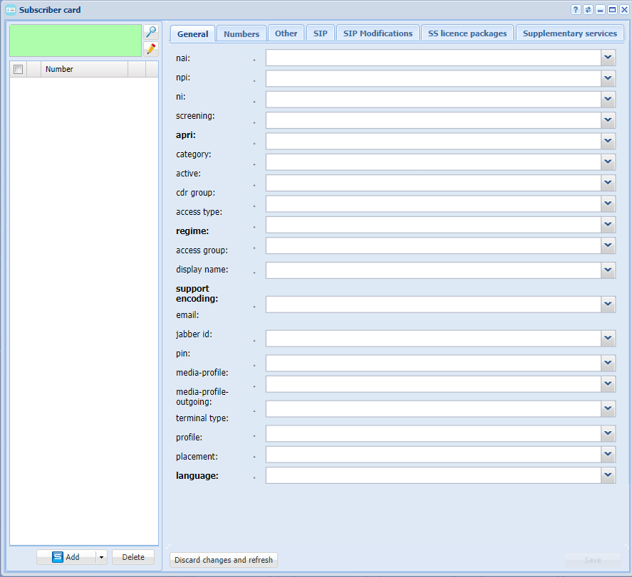
Figure 15 — Subscriber card application view
It is possible to create SIP subscribers and virtual subscribers in the application.
For users with a physical termination, the functionality of the SIP subscriber is used, while the virtual subscriber is used when functionality without physical endings is needed. For example, the number for accessing the ivr script.
To create new subscribers, click on the Add button.
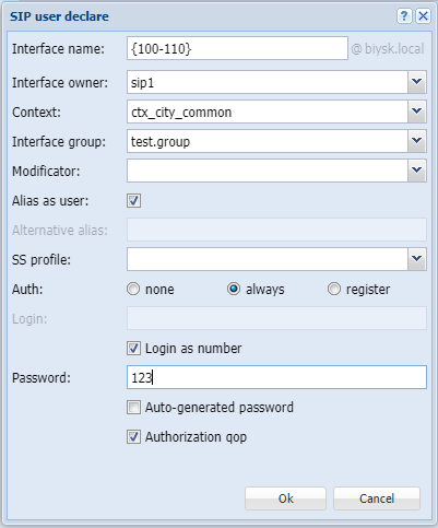
In the dialog box that opens, specify the following parameters:
- Context — routing context, select the one that you created, for example "test_name";
- Interface name — number or group of numbers that is assigned to the subscriber, for example {100-110};
- Alias as user — setting that binds entity number, alias and user with the same name, in the example the setting is activated;
- Authorization — procedure for verifying the authenticity of the user's rights to access data, in the example always is used.
- Login — use WHATEVER.
- Password — can be set or used generated by the system.
 ->
->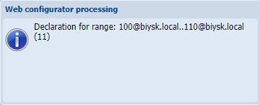
Figure 16 — Example of identifying subscribers in a domain
Creating and applying routing contexts for a domain
Routing is responsible for finding the number and then addressing the call. At least one routing context must be configured for the system to operate correctly.
Routing is configured in Routing Manager application.
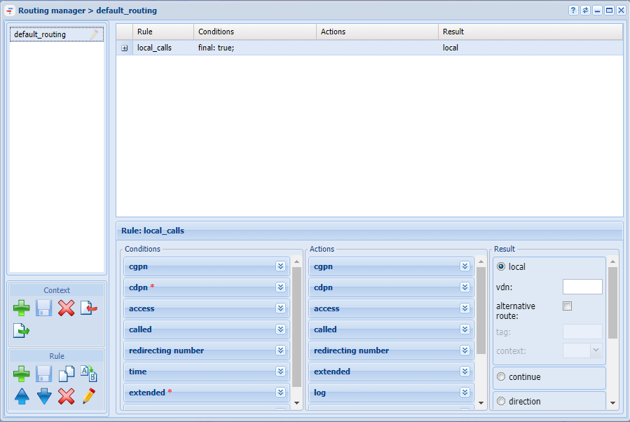
Figure 17 — Routing manager application view
Example of creating a context and a few rules in it:
- In the left part of the window in the Context section click the Create context button;
- In the dialog box that opens, indicate the name of the context as well as the type of context — empty context:
1. In the left part of the window in the Context section click the Create context button ;
2. In the dialog box that opens, indicate the name of the context, as well as the type of context — empty context:
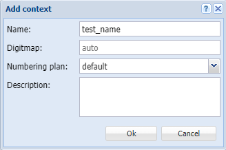
3. Click Save context  ;
;
Create 4 rules in this context:
- rule1 — rule for accessing TAU-72 trunk;
- rule2 — local routing rule for numbers 101-105;
- rule3 — rule for entering the ivr;
- rule4 — exception rule.
To create a new rule, select the created context and click Create rule. In the window that appears, enter name of the rule. Then save the newly created rules.
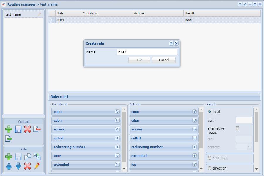
Figure 18 — Creating routing context rule
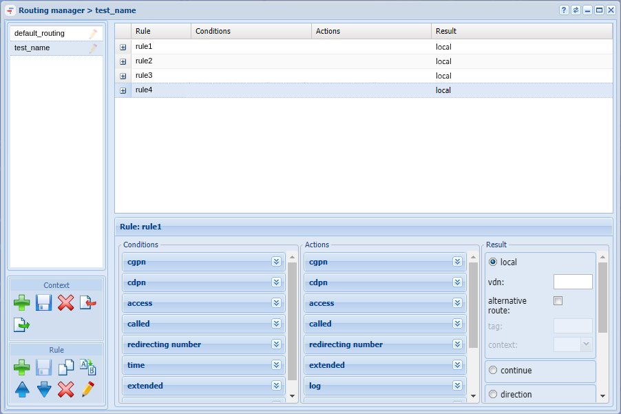
Figure 19 — Defining rules
At the moment, the trunk that can be referred in a rule is not defined, however it is possible to specify the numbers by which the selection will be made.
Go to the lower part of the screen by clicking on the rule1, where the areas for editing the routing context are located. It is conditionally defined in the example that selection for entering the trunk will be carried out based on the characteristics of the called subscriber number (CDPN), and the numbers in the trunk should start with digit 4.
Functionally, the routing context is divided into three parts:
- Condition — section defining the expressions for selection according to the proposed criteria;
- Action — section that converts the signs of numbers to a specific value;
- Result — section that completes the routing and determines its result.
rule1: To access the trunk, edit each part correctly:
- In the conditions section, go to the CDPN tab. Enter the phone numbers that are assigned to the trunk in the Number field. For example, to define numbers from 106 to 107, enter condition 10(6-7);
- In the actions section, go to the CDPN tab. Enter a mask to change the number in the Number field. For example, to add number 4 before the number, fill in the field with the following expression 4{1,2,3};
- Click Save rule and Save Context buttons to apply changes.
To configure the result field, the trunk must be defined in the system, so return to configuring this rule a little later.
Configure remaining rules in the same way.
For rule2:
- In CDPN tab in conditions section, enter phone numbers that are behind the trunk in "Number" field. For example, to define numbers from 101 to 105, enter condition 10(1-5);
- In the result section, define the result as local (e. local routing);
- Click Save rule and Save Context buttons to apply changes.
For rule 3, assume that subscribers with numbers 108, 109 and 110 get into the informant ivr script before calling further.
- In CDPN tab in conditions section, enter the phone numbers for which the selection will be in the field "Number", for example 1(10.08-09).
- Click Save rule and Save Context buttons to apply changes.
To configure the result field, ivr script must be defined in the system, so return to configuring this rule a little later.
For rule 4, define an exception rule — this is a rule that works in case any other rules fail.
- By default, this rule is created in the system in default_routing context. The % symbol is written to the called number in the conditions, and the result is local routing, however, it is recommended to create this rule at the end if assigning to the subscriber a context other than default_routing.
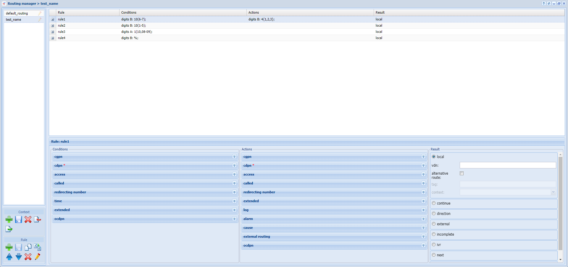
Figure 20 — Example of configuring routing context
Creating trunk
To create and edit trunk parameters in the system, use the Trunk manager application.
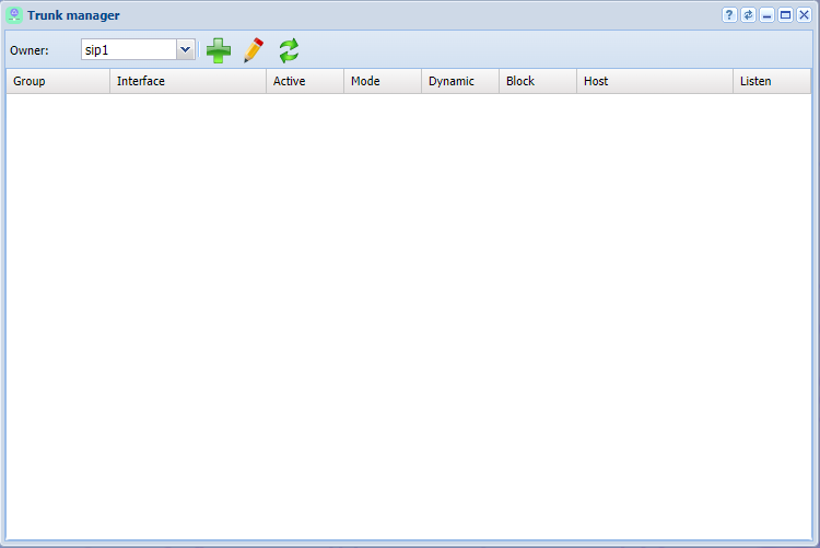
Figure 21 — Trunk Manager application view
To define a trunk in the system, click on the Trunk declare button, define parameters in the dialog box that opens:
- Name — assign trunk name by which it can be identified in the system;
- Context — apply previously created test_name routing context;
- Group — select the interface group created when defining 'test.group' subscribers;
- IP address group (IPSet) — 'ipset1' address group created on the domain;
- Registration — if trunk is used, then enable this parameter, it is not used in the example;
- Host [:port] — destination IP address of the trunk — 10.0.3.100;
- Listen port — transport port where traffic from the trunk will be listened to, corresponds to the port assigned to the IP address group.
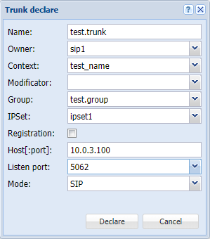 →
→
Figure 22 — Creating a trunk
Creating IVR script
To create IVR, use the IVR editor application.
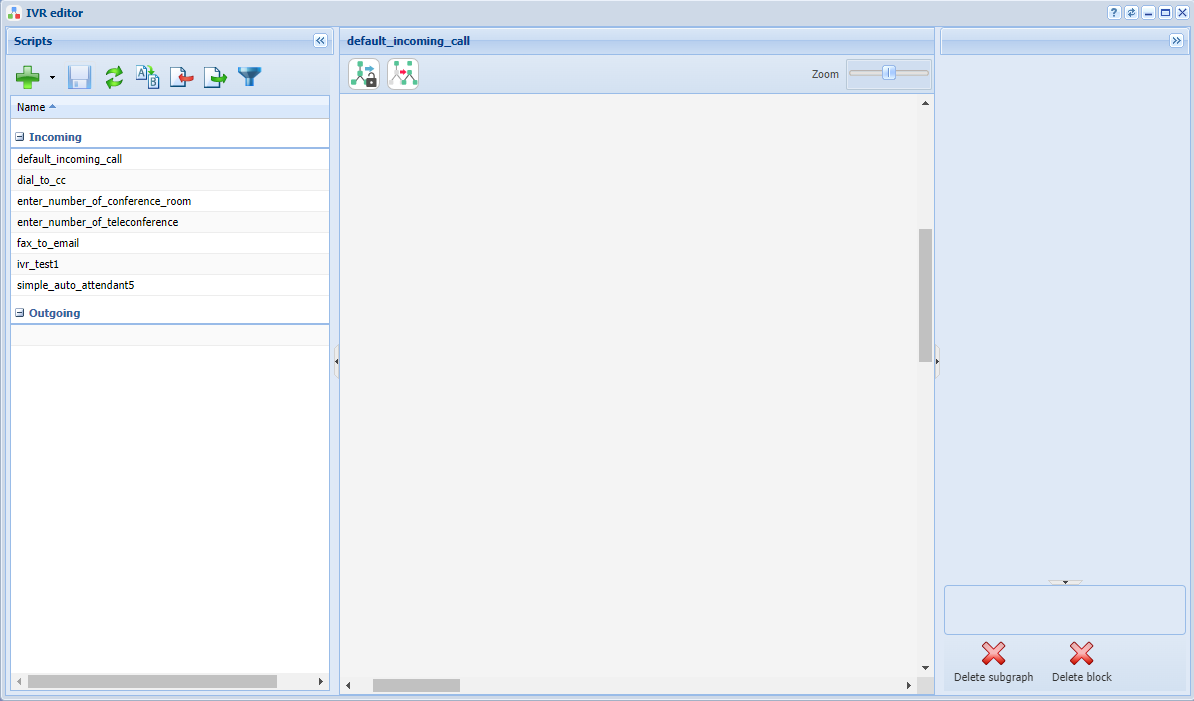
Figure 23 — IVR editor application view
To create a script, click on the Add button, select script type (in this case there is a script for incoming calls), specify the name of the script in the dialog box, for example "test_ivr".
After creating the script, a flowchart will appear in the main editor window.
In figures below is shown an example of making a script that plays a pre-recorded phrase to the caller when triggered, and then continues the call.
- Info — block that plays messages until the user responds. A tone generator is used as a recorded phrase:
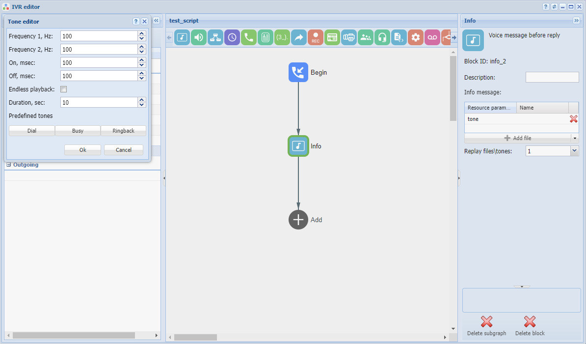
Figure 24 — View of the IVR workspace with the Info block settings
- Dial — block that makes a call to a given number. To continue the call, apply the predefined CDPN variable:
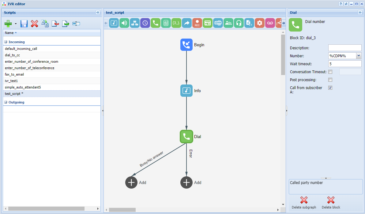
Figure 25 — View of the IVR workspace
Completing routing configuration
To complete routing, open Routing manager application and in rules rule1 and rule3 adjust the corresponding routing results, and follow the steps below:
- rule1: select the "external" sub-item in the Result section. In the Value field of the Directions table add the trunk created earlier, then save the rule .
- rule3: select the "ivr" sub-item in the Result section. In the script field add the previously created ivr script, then save the rule and the context .
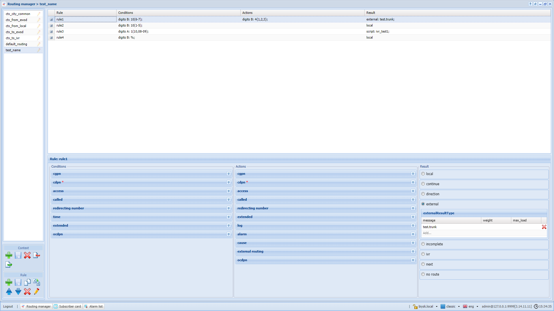
Figure 26 —Type of routing context
Configuring services
To configure the services, perform several actions:
- Install services via СoСon;
- Add services for the domain to the access list (access-list) via СoСon;
- Then any service in the access list becomes applicable on the subscriber or trunk.
To log in to the СoСon CLI, use the terminal or Console application.
After logging in to CoCon, write the following commands:
- To install services in the system:
cluster/storage/ds1/ss/install ds1@ecss1 *
- After successful installation of the services, enter the following line to add access to them:
cluster/storage/ds1/ss/access-list add test_domain *
The "*" symbol means that the command will be applied to all available elements in the system. If you need to install a specific service, enter its name instead of "*".
To connect the services, the subscriber must open the subscriber card, select the subscriber from the list and go to the Additional services tab.
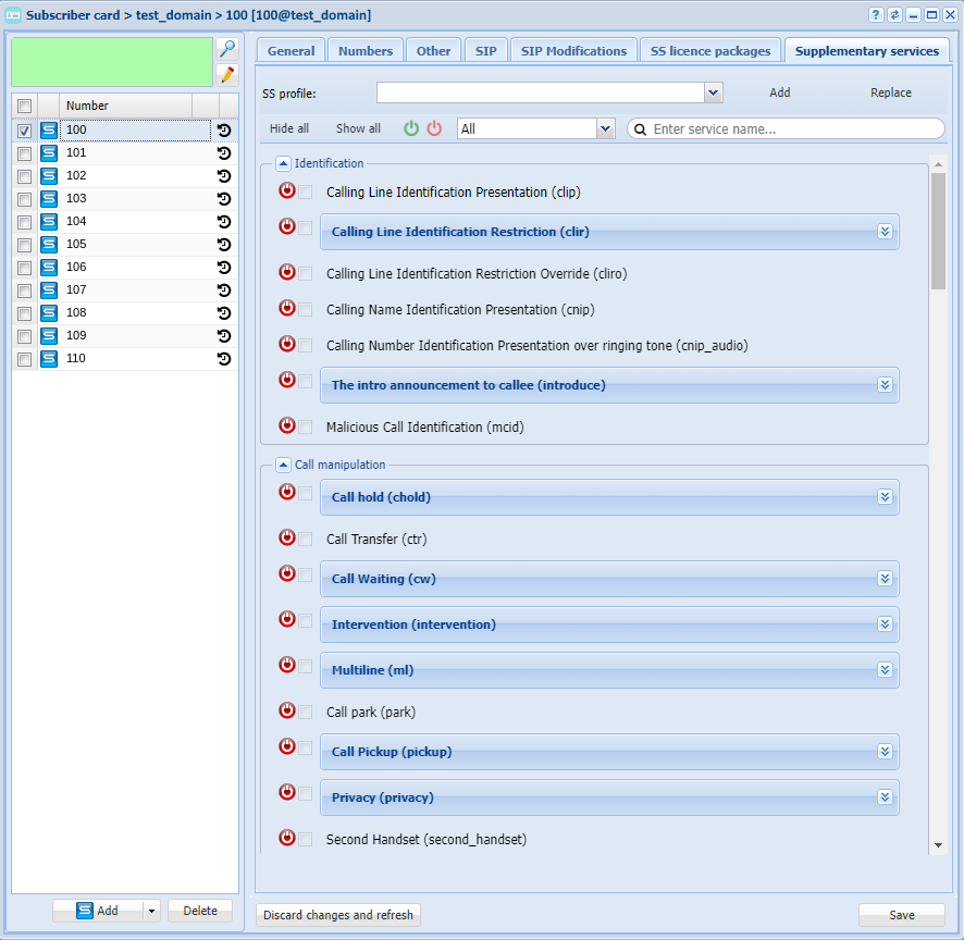
Figure 27 — Example of configuring services
To activate subscriber services, connect them by clicking the button  , then activate and configure (you can read more in the Subscriber card application section).