General information
SoftWLC is a Wi-Fi software controller which includes a number of modules performing various functions to provide a comprehensive solution for organizing centralized Wi-Fi networks with Portal and Enterprise authorization. According to project requirements, certain modules can be included in the system or excluded from it.
Key features of SoftWLC:
- Management and monitoring of Eltex network equipment on which the Wi-Fi solution is based.
- Flexible distribution of administrative policies of access of SoftWLC users to various objects and functions within a carrier's distributed hierarchy.
- Organization of a Hotspot with portal authorization, within which it is possible to:
- Integrate advertising providers' resources into the portal
- Provide integration with payment systems
- Provide branding the portal design according to customer requirements
- Enterprise authorization
- Integration with external Active Directory
- Providing the end customer with a web tool for managing the service, portal branding and creating user accounts
- SSID scheduling
Main modules of SoftWLC
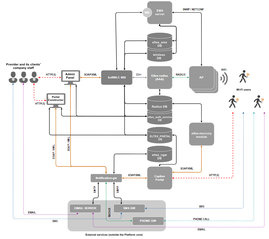
- EMS server — the central component of the SoftWLC, which provides management and monitoring of other system modules, provides the operator with a GUI for working with SoftWLC.
- SoftWLC NBI — interface for integration with the carrier's OSS.
- WEB portal (Captive Portal) — a web-based module that provides a set of WEB portals for user authorization in hotspot networks, as well as the Portal Constructor for their customization. The list of WEB portal features includes integration with notification gateway, autogeneration of Wi-Fi user accounts in the database (implemented via eltex-mercury).
- B2B Admin Panel — a web resource designed to provide the user with a convenient interface for creating accounts for new Wi-Fi subscribers and basic service management operations, for example, changing the SSID name. Can be used by provider or provider clients' employees.
- Database — a single database of SoftWLC, based on MySQL. It contains all the data about the system: from hardware configuration to user activity statistics. The module consists of several databases.
- RADIUS server — a module intended for AAA operations (Authentication, Authorization, Accounting) based on freeRADIUS.
- DHCP server — a module intended for issuing dynamic IP addresses to user points and Wi-Fi clients. It is based on isc-dhcp-server. Optionally carriers can use their own DHCP-servers.
- APB service — a service designed for centralized synchronization of user status information between access points. It is required for seamless customer roaming between Hotspots.
- Notification Gateway — provides centralized exchange of platform elements with external systems allowing sending SMS and email messages and performing call-based authorization. This module interacts with B2B Admin Panel and WEB portal.
- PCRF — required for SoftWLC and ESR-1000 interaction in BRAS mode, when ESR-1000 implements Wi-Fi subscribers' Internet access policies and redirects users to the authorization portal, and for establishing sogtGRE data tunnels to access points.
Typical connection diagrams
The simplest minimal diagram
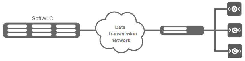
In the minimum configuration, the solution is deployed on two servers: each server hosts all modules with Active-Active redundancy. SoftWLC servers are included in the operator's data transmission network. L3 connectivity is organized between them and the access points. This is enough to start using the product. Management interfaces are configured on the access points to interact with SoftWLC in a separate management VLAN. Client data goes from APs in client VLANs (usually a separate VLAN for each SSID) to the operator's network and then to the Internet.
Global distributed diagram for large carriers
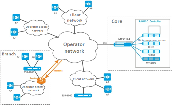
This diagram is typical for large distributed networks deployed within several cities or regions. SoftWLC is deployed on several servers depending on the planned load. In the maximum configuration, the solution is deployed on 10 servers: EMS, WEB portal and APB are installed on the first pair of servers, Database – on the second pair, RADIUS – on the third pair, DHCP – on the fourth pair. It is recommended to set Admin Panel on a separate redundant front-end server with maximum security settings. All servers are connected to the switch pair working in the stack which in its turn is connected to the redundant router pair in the operator's network. In case the customer wishes to terminate subscriber sessions on their premises, it is possible to relocate one or more ESR-1000s to the customer's network. If the operator has a globally distributed network structure united by trunk lines, it is possible to relocate ESR-1000 routers to branches of the network.
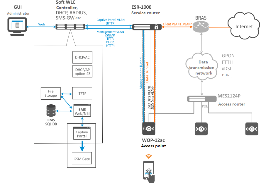
Diagram with usage of ESR-1000 service routers
ESR-1000 service routers are used in the network for several purposes:
- removing the load of terminating subscriber sessions from the carrier's network;
- organizing automatic tunneling (L2 over GRE) between ESR-1000 and access points. The need for tunneling is due to the requirement for isolation of subscriber traffic and management traffic. Due to the use of tunnels, a point can be included in a customer's or third-party operator's access network, as well as included in ports using access mode when processing L2-level headers.
- Network security by configuring the firewall built in ESR-1000.
- NAT (optional).
- VRF organization.
Access points can be connected both to the operator's own access network and included in the customer's access network. When enabled, access points build Soft GRE tunnels to ESR-1000 service routers in the carrier's network, through which further data is routed to SoftWLC or to the Internet.
Soft GRE tunnels are made between the ESR-1000 and the access points through the operator's L3 infrastructure. Two tunnels are formed from each access point: Management tunnel to transmit management traffic and Data tunnel to transmit subscriber traffic.
Inside the Management tunnel, the management traffic of the access point is transmitted in a separate management network. This subnet is invisible to the operator's L3 segment due to the GRE tunnel headers. Within the Data tunnel, subscriber traffic is transmitted. This traffic is terminated at ESR-1000 and further routed to the operator's network (towards its NAT).
 System requirements for SoftWLC server
The SoftWLC software controller must be installed on a server powered by Ubuntu Server 16.04 LTS / Ubuntu Server 18.04 LTS / Astra Linux Common Edition 2.12.44 / Debian 9 / Astra Linux Special Edition 1.7.1
Support is provided only for Ubuntu Server 16.04 LTS / Ubuntu Server 18.04 LTS / Astra Linux Common Edition 2.12.44 / Debian 9 / Astra Linux Special Edition 1.7.1
When selecting a server, the following system requirements must be taken into account (requirements are provided for the VM without taking into account system redundancy):
Number of devices | VM name | CPU core, Xeon | RAM, GB | HDD, GB |
|---|---|---|---|---|
10 – 200 APs | SoftWLC | 4, 64-bit x86 CPUs | 8 | 200 |
| 200 – 500 APs | SoftWLC | 4, 64-bit x86 CPUs | 16 | 200 |
| 500 – 1000 APs | SoftWLC | 6, 64-bit x86 CPUs | 12 | 200 |
| DataBase | 4, 64-bit x86 CPUs | 16 | 200 | |
| 1000 – 2000 APs | EMS | 6, 64-bit x86 CPUs | 14 | 200 |
| RADIUS | 4, 64-bit x86 CPUs | 6 | 100 | |
| WEB-Portal | 4, 64-bit x86 CPUs | 8 | 40 | |
MySQL | 4, 64-bit x86 CPUs | 24 | 500 | |
| MongoDB | 4, 64-bit x86 CPUs | 10 | 200 |