Installation and connection
This section describes installation of the device into a rack and connection to a power supply.
Support brackets mounting
The delivery package includes support brackets for rack installation and mounting screws to fix the device case on the brackets. To install the support brackets:
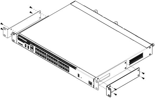
Figure 60 – Support brackets mounting
- Align four mounting holes in the support bracket with the corresponding holes in the side panel of the device.
- Use a screwdriver to screw the support bracket to the case.
- Repeat steps 1 and 2 for the second support bracket.
Device rack installation
To install the device to the rack:
- Attach the device to the vertical guides of the rack.
- Align mounting holes in the support bracket with the corresponding holes in the rack guides. Use the holes of the same level on both sides of the guides to ensure the device horizontal installation.
- Use a screwdriver to screw the router to the rack.
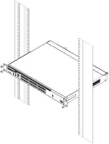
Figure 62 – Device rack installation
Device ventilation system is implemented using 'front-rear' layout. Vents are located on the front and side panels of the device; ventilation modules are located at the rear. Do not block air inlet and outlet vents to avoid components overheating and subsequent device malfunction.
Connection to the vESR
To install and connect to vESR, go to the vESR documentation section.
ESR-1000, ESR-1200, ESR-1500, ESR-1511, ESR-1700, ESR-3100, ESR-3200 power module installation
ESR-1000/1200/1500/1511/1700/3100/3200 routers can operate with one or two power modules. The second power module installation is necessary when the device operates under strict reliability requirements.
From the electric point of view, both places for power module installation are identical. In the context of device operation, the power module can be in the main and reserve slot. For information on priority see table 'Description of connectors, LEDs and controls located on router'. Power modules can be inserted and removed without powering the device off. When additional power module is inserted or removed, the router continues operation without reboot.
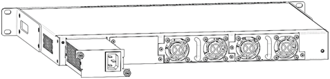
Figure 63 – Power module installation
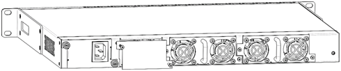
Figure 64 – Plug installation
Power module fault indication may be caused not only by the module failure, but also by the absence of the primary power supply.
The state of power modules can be checked by the indication on the front panel of the router (see Light indication section) or by diagnostics, available through the router management interfaces.
Connection to Power Supply
- Ground the case of the device prior to connecting it to the power supply. An insulated multiconductor wire should be used for earthing. The device grounding and the earthing wire cross-section should comply with Electric Installation Code.
- If a PC or another device is supposed to be connected to the router console port, the device should be also securely grounded.
- Connect the power supply cable to the device. Depending on the delivery package, the device can be powered by AC or DC electrical network. To connect the device to AC power supply, use the cable from the delivery package. To connect the device to DC power supply, use wires with a minimum cross-section of 1 mm2.
- Turn the device on and check the front panel LEDs to make sure the terminal is in normal operating conditions.
SFP transceiver installation and removal
Optical modules can be installed when the terminal is turned on or off.
Transceiver installation
1. Insert the top SFP module into a slot with its open side down, and the bottom SFP module with its open side up.
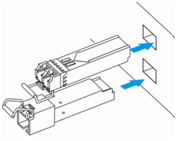
Figure 65 – SFP transceivers installation
2. Push the module into the device housing until it is secured with a clicking sound.
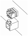
Figure 66 – Installed SFP transceivers
Transceiver removal
1. Flip the module handle to unlock the latch.
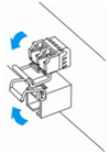
Figure 67 – Opening SFP transceiver latch
2. Remove the module from the slot.
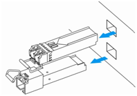
Figure 68 – SFP transceivers removal