Product description
Purpose
ESR series devices are the high performance multi-purpose network routers. Device combines traditional network features with a complex multi-tier approach to routing security, and ensures robust corporate environment protection.
Device has a built-in firewall that enables protection of your and organization network environment and supports latest data security, encryption, authentication and intrusion prevention features.
Device contains software and hardware means of data processing. Top performance is achieved through optimal distribution of data processing tasks between different subsets of the device.
Functions
Interface functions
Table 1 lists interface functions of the device.
Table 1 – Device interface functions
Cable connection polarity detection | Automatic cable type detection – crossover cable or straight-through cable.
|
| The backpressure routing method is utilized in half-duplex connections for management of data streams, coming from the opposite devices, by means of collisions. This method allows to avoid buffer overruns and the loss of data. |
Flow control | Flow control allows to interconnect the low-speed and the high-speed devices. To avoid buffer overrun, the low-speed device gains the ability to send PAUSE packets, that will force the high-speed device to pause the packet transmission. |
| Link aggregation allows to increase the communication link bandwidth and robustness. Router supports static and dynamic link aggregation. For dynamic aggregation, link group management is performed via LACP protocol. |
MAC table functions
Table 2 lists MAC address processing functions of the device.
Table 2 – MAC address processing functions
MAC table | MAC address table sets the correspondence between MAC addresses and device interfaces and is used for data packet routing. Routers support table capacity up to 128K of MAC addresses and reserve specific MAC addresses for the system use. |
Learning mode | MAC address table may contain either static addresses or addresses learnt during data packet transition through the device. Learning involves registration of packet source MAC addresses with their binding to ports and VLANs. Afterwards, this data is used for incoming packet routing. Registered MAC address lifetime is limited. Administrator may adjust this setting. If destination MAC address specified in the packet that was received by the device is not listed in the table, this packet will be sent further as a broadcast packet within L2 segment of the network. |
Second-layer functions of OSI model
Table 3 lists second-layer functions and special aspects (OSI Layer 2).
Table 3 – Second-layer functions description (OSI Layer 2)
VLAN support | VLAN (Virtual Local Area Network) is a solution used for splitting a network into separate segments on L2 level. VLAN utilization allows to increase the operation stability for large networks by splitting them into smaller networks, isolate diversified data traffic by type and solve many other tasks. Routers support various VLAN management methods:
|
Spanning Tree Protocol1 | The main task of Spanning Tree Protocol is to exclude redundant network links and convert network topology into the tree-like structure. Common areas of protocol application involve the prevention of network traffic loops and establishing of redundant communication links. |
1 In the current firmware version, this functionality is supported only by ESR-1000 router.
Third-layer functions of OSI model
Table 4 lists third-layer functions (OSI Layer 3).
Table 4 – Third-layer functions description (OSI Layer 3)
Static IP routes | Administrator of the router can add or remove static entries into/from the routing table. |
Dynamic routing
| With dynamic routing protocols, the device will be able to exchange the routing information with neighbouring routers and automatically create a routing table. Router supports the following protocols: RIPv2, RIPng, OSPFv2, OSPFv3, IS-IS, BGP. |
ARP table | ARP (Address Resolution Protocol) is a protocol used for resolution of the network and data-link layer addresses. ARP table contains information on the established correspondence. Correspondence is established on the basis of the network device response analysis; device addresses are requested with broadcast packets. |
DHCP client
| DHCP (Dynamic Host Configuration Protocol) protocol enables automation of the network device management process. DHCP client allows the router to obtain the network address and additional settings from the external DHCP server. As a rule, this method is used for obtaining network settings of a public network operator (WAN). |
DHCP server | DHCP server enables automation and centralization of the network device configuration process. DHCP server allocated on a router allows for a complete solution for the local area network support. DHCP server integrated into the router assigns IP addresses to network devices and transfers additional network settings, e.g. server addresses, network gateway addresses and other necessary settings. |
DHCP Relay | The DHCP Relay functionality is designed to redirect broadcast DHCP Discover packets from one broadcast domain to unicast DHCP Discover packets in another broadcast domain. |
NAT, Network Address Translation | Network address translation is a mechanism that translates IP addresses and port numbers for transit packets. NAT function allows to minimize the quantity of IP address used through translation of multiple internal network IP addresses into a single external public IP address. NAT conceals local area network internal structure and allows to enhance its security. Routers support the following NAT options:
|
Traffic tunneling functions
Table 5 – Traffic tunneling functions
Tunneling protocols | Tunneling is a method of packet conversion during their network transfer that involves the replacement, modification and addition of a new packet network header. This method may be used for negotiation of transport protocols when the data is transferred through the transit network as well as for creation of secured connections where tunneled data is being encrypted. Routers support the following types of tunnels:
|
Management and configuration functions
Table 6 – Basic management and configuration functions
Configuration file download and upload | Device parameters are saved into the configuration file that contains configuration data for the specific device ports as well as for the whole system. The following protocols may be used for file transfers: TFTP, FTP, and SCP. |
Command line interface (CLI) | CLI management is performed locally via serial port RS-232, or remotely via Telnet, SSH. Console command line interface (CLI) is the industrial standard. CLI interpreter contains the list of commands and keywords that will help the user and reduce the amount of input data. |
Syslog | Syslog protocol is designed for transmission of system event messages and event logging. |
Ping, traceroute | Ping and traceroute utilities allow you to check the availability of network devices and identify data transfer routes in IP networks. |
Controlled access management – privilege levels | Routers support system access level management for users. Access levels enable responsibility areas management for device administrators. Access levels are numbered from 1 to 15; Level 15 stands for full access to device management features. |
Authentication | Authentication is a user identity check procedure. Routers support the following authentication methods:
|
SSH Server/ | SSH and Telnet server features allow you to establish connection to the device and perform device management. |
Automatic configuration restore | Device features automatic configuration restore system designed to prevent remote access loss after re-configuration. If the configuration change is not confirmed in the specified time, configuration will be rolled back to the last known state. |
Network security functions
Table 7 lists network security functions of the device.
Table 7 – Network security functions
Security zones | All router interfaces are distributed by security areas. For each zone pair, you can set the rules that determine the possibility of data transmission between zones, data traffic filtering rules. |
Data filtering | For each zone pair, you can specify the rule set that manages the filtering process for data transmitted through the router. Device command interface provides appropriate means for detailed configuration of the traffic classification rules and to apply the resulting solution for traffic transmission. |
Main specifications
Table 8 lists main specifications of the router.
Table 8 – Main specifications
General parameters | ||
|---|---|---|
Interfaces | ESR-3200 | 12 × 1000BASE-X/10GBASE-R/25GBASE-R 1 × Console RS-232 (RJ-45) 1 × OOB port 1 × USB 2.0 1 × microSD card slot |
| ESR-3100 | 8 × Combo Ethernet 10/100/1000BASE-T/1000BASE-X 8 × 10GBASE-R/1000BASE-X (SFP+/SFP) 1 × Console RS-232 (RJ-45) 2 × USB 3.0 1 × SD card slot | |
ESR-1700 | 4 × Combo Ethernet 10/100/1000BASE-T/1000BASE-X 8 × 10GBASE-R/1000BASE-X (SFP+/SFP) 2 × Hard disk installation slot 1 × Console RS-232 (RJ-45) 1 × OOB port 2 × USB 2.0 | |
ESR-1511 | 4 × Combo Ethernet 10/100/1000BASE-T/1000BASE-X 4 × Ethernet 10/100/1000BASE-T (RJ-45) 4 × 10GBASE-R/1000BASE-X (SFP+/SFP) 2 × 40GBASE-X (QSFP+) 1 × Console RS-232 (RJ-45) 1 × OOB port 2 × USB 2.0 1 × SD card slot | |
ESR-1500 | 4 × Combo Ethernet 10/100/1000BASE-T/1000BASE-X 4 × Ethernet 10/100/1000BASE-T (RJ-45) 4 × 10GBASE-R/1000BASE-X (SFP+/SFP) 1 × Console RS-232 (RJ-45) 1 × OOB port 2 × USB 2.0 1 × SD card slot | |
ESR-1200 | 4 × Combo Ethernet 10/100/1000BASE-T/1000BASE-X 12 × Ethernet 10/100/1000BASE-T (RJ-45) 8 × 10GBASE-R/1000BASE-X (SFP+/SFP) 1 × Console RS-232 (RJ-45) 2 × USB 2.0 1 × SD card slot | |
ESR-1000 | 24 × Ethernet 10/100/1000BASE-T (RJ-45) 2 × 10GBASE-R/1000BASE-X (SFP+/SFP) 1 × Console RS-232 (RJ-45) 2 × USB 2.0 1 × SD card slot | |
ESR-200 | 4 × Combo Ethernet 10/100/1000BASE-T/1000BASE-X 4 × Ethernet 10/100/1000BASE-T (RJ-45) 1 × Console RJ-45 1 × USB 3.0 1 × USB 2.0 1 × SD card slot | |
ESR-100 | 4 × Combo Ethernet 10/100/1000BASE-T/1000BASE-X 1 × Console RS-232 (RJ-45) 1 × USB 3.0 1 × USB 2.0 1 × SD card slot | |
| ESR-30 | 4 × Ethernet 10/100/1000BASE-T (RJ-45) 2 × 10GBASE-R/1000BASE-X (SFP+/SFP) 1 × Console RS-232 (RJ-45) 1 × USB 3.0 1 × USB 2.0 1 × microSD card slot | |
ESR-21 | 8 × Ethernet 10/100/1000BASE-T (RJ-45) 4 × 1000BASE-X (SFP) 3 × Serial port RS-232 1 × Console RS-232 (RJ-45) 1 × USB 3.0 1 × USB 2.0 1 × SD card slot | |
ESR-20 | 2 × Combo Ethernet 10/100/1000BASE-T/1000BASE-X 2 × Ethernet 10/100/1000BASE-T (RJ-45) 1 × Console RS-232 (RJ-45) 1 × USB 3.0 1 × USB 2.0 1 × SD card slot | |
| ESR-15 | 4 × Ethernet 10/100/1000BASE-T (RJ-45) 2 × 1000BASE-X (SFP) 1 × Console RS-232 (RJ-45) 2 × USB 2.0 | |
ESR-14VF | 8 × Ethernet 10/100/1000BASE-T (RJ-45) 1 × 1000BASE-X (SFP) 1 × Console RS-232 (RJ-45) 4 × FXS 2 × USB 2.0 | |
ESR-12VF | 8 × Ethernet 10/100/1000BASE-T (RJ-45) 1 × 1000BASE-X (SFP) 1 × Console RS-232 (RJ-45) 3 × FXS 1 × FXO 2 × USB 2.0 | |
ESR-12V | 8 × Ethernet 10/100/1000BASE-T (RJ-45) 1 × Console RS-232 (RJ-45) 3 × FXS 1 × FXO 2 × USB 2.0 | |
ESR-10 | 4 × Ethernet 10/100/1000BASE-T (RJ-45) 2 × 1000BASE-X (SFP) 1 × Console RS-232 (RJ-45) 2 × USB 2.0 | |
Types of optical transceivers | ESR-3200 | 1000BASE-X SFP 10GBASE-R SFP+ 25GBASE-R SFP28 |
| ESR-1511 | 1000BASE-X SFP 10GBASE-R SFP+ 40GBASE-X QSFP+ | |
ESR-1700 ESR-3100 ESR-1500 ESR-1200 ESR-1000 ESR-30 | 1000BASE-X SFP 10GBASE-R SFP+ | |
ESR-200 ESR-100 ESR-21 ESR-20 ESR-15 ESR-14VF ESR-12VF ESR-10 | 1000BASE-X SFP | |
| ESR-15 | 1000BASE-R SFP+ | |
Duplex or half-duplex interface modes |
| |
Maximum bandwidth in | ESR-1700 ESR-1511 ESR-1500 ESR-1200 | 160 Gbps |
ESR-1000 | 88 Gbps | |
Data transfer rate | ESR-3200 |
|
| ESR-1511 |
| |
ESR-3100 ESR-1700 ESR-1500 ESR-1200 ESR-1000 |
| |
ESR-200 ESR-100 ESR-21 ESR-20 ESR-15 ESR-14VF ESR-12V(F) ESR-10 |
| |
Number of VPN tunnels | ESR-3200 ESR-3100 ESR-1700 ESR-1511 ESR-1500 ESR-1200 ESR-1000 | 500 |
ESR-200 ESR-100 ESR-30 ESR-21 ESR-20 | 250 | |
ESR-15 ESR-14VF ESR-12V(F) ESR-10 | 10 | |
Number of static routes | ESR-3200 ESR-3100 ESR-1700 ESR-1511 ESR-1500 ESR-1200 ESR-1000 ESR-200 ESR-100 ESR-30 ESR-21 ESR-20 | 11k |
ESR-15 ESR-14VF ESR-12V(F) ESR-10 | 1k | |
Number of concurrent sessions | ESR-3200 ESR-3100 ESR-1700 ESR-1511 ESR-1500 ESR-1200 ESR-1000 | 512k |
ESR-200 ESR-100 ESR-30 ESR-21 ESR-20 | 256k | |
ESR-15 ESR-14VF ESR-12V(F) ESR-10 | 4k | |
VLAN support | up to 4k active VLANs according to 802.1Q | |
Number of BGPv4/BGPv6 routes | ESR-3200 ESR-3100 ESR-1700 ESR-1511 ESR-1500 ESR-1200 ESR-1000 | 5M |
ESR-200 ESR-100 ESR-30 ESR-21 ESR-20 | 2.5M | |
ESR-15 ESR-14VF ESR-12V(F) ESR-10 | 1M | |
Number of OSPFv2/OSPFv3/IS-IS routes | ESR-3200 ESR-3100 ESR-1700 ESR-1511 ESR-1500 ESR-1200 ESR-1000 | 500k |
ESR-200 ESR-100 | 300k | |
ESR-30 ESR-21 ESR-20 ESR-15 ESR-14VF ESR-12V(F) ESR-10 | 30k | |
Number of RIP/RIPng routes | ESR-3200 ESR-3100 ESR-1700 ESR-1511 ESR-1500 ESR-1200 ESR-1000 ESR-200 ESR-100 ESR-30 ESR-21 ESR-20 | 10k |
ESR-15 ESR-14VF ESR-12V(F) ESR-10 | 1k | |
MAC address table | ESR-1700 ESR-1511 ESR-1500 ESR-1200 | 128k entries |
ESR-3200 ESR-1000 | 16k entries | |
ESR-3100 ESR-200 ESR-100 ESR-30 ESR-21 ESR-20 ESR-15 ESR-14VF ESR-12V(F) ESR-10 | 2k bridge entries | |
FIB size | ESR-1700 | 3.0M |
ESR-3200 ESR-3100 ESR-1511 ESR-1500 ESR-1200 ESR-1000 | 1.7M | |
ESR-200 ESR-100 ESR-30 ESR-21 ESR-20 | 1.4M | |
ESR-15 ESR-14VF ESR-12V(F) ESR-10 | 800k | |
VRF Lite | 32 | |
L3 interfaces | ESR-3200 ESR-3100 ESR-1700 ESR-1500 ESR-1511 ESR-1200 ESR-1000 ESR-200 ESR-100 ESR-30 ESR-21 ESR-20 | 4000 |
ESR-15 ESR-14VF ESR-12V(F) ESR-10 | 200 | |
Compliance | IEEE 802.3 10BASE-T Ethernet IEEE 802.3u 100BASE-T Fast Ethernet IEEE 802.3ab 1000BASE-T Gigabit Ethernet IEEE 802.3z Fiber Gigabit Ethernet IEEE 802.3ba 40GBASE-SR4, 40GBASE-LR4 ANSI/IEEE 802.3 Speed autodetection IEEE 802.3x Data flow control IEEE 802.3ad LACP link aggregation IEEE 802.1q VLAN virtual local networks IEEE 802.1v IEEE 802.3ac IEEE 802.3ae IEEE 802.1D IEEE 802.1w IEEE 802.1s | |
Control | ||
Local control | CLI | |
Remote control | TELNET, SSH | |
Physical specifications and ambient conditions | ||
Power supply | ESR-1700 | AC: 176–264 V, 50–60 Hz DC: 36–72 V Power options:
|
ESR-3200 ESR-3100 ESR-1511 ESR-1500 ESR-1200 ESR-1000 | AC: 100–240 V, 50–60 Hz DC: 36–72 V Power options:
| |
ESR-200 ESR-100 ESR-30 ESR-21 ESR-20 ESR-14VF ESR-12V(F) | AC: 100–264 V, 50–60 Hz | |
| ESR-15 | 220 V/12 V, 2 A DC power adapter | |
ESR-10 | 220 V/12 V, 1.5 A DC power adapter | |
Maximum power consumption: | ESR-3200 | 118 W |
| ESR-3100 | 123 W | |
ESR-1700 | 250 W | |
ESR-1511 | 128 W | |
ESR-1500 | 125 W | |
ESR-1200 | 85 W | |
ESR-1000 | 75 W | |
ESR-200 | 25 W | |
ESR-100 | 20 W | |
| ESR-30 | 26 W | |
ESR-21 | 32 W | |
ESR-20 | 25 W | |
| ESR-15 | 18 W | |
ESR-14VF ESR-12V(F) | 22 W | |
ESR-10 | 9 W | |
Weight | ESR-3200 | 5 kg |
ESR-3100 | 4.34 kg | |
| ESR-1700 | 12 kg | |
ESR-1511 ESR-1500 | 7 kg | |
ESR-1200 | 5.5 kg | |
ESR-1000 | 3.6 kg | |
ESR-200 ESR-100 | 2.5 kg | |
| ESR-30 | 1.8 kg | |
ESR-21 | 3.15 kg | |
ESR-20 | 2 kg | |
| ESR-15 | 0.325 kg | |
ESR-14VF ESR-12V(F) ESR-10 | 1 kg | |
Dimensions (W × H × D) | ESR-3200 ESR-3100 | 430 × 44 × 330 mm |
| ESR-1700 | 440 × 88 × 490 mm | |
ESR-1511 ESR-1500 | 430 × 44 × 425 mm | |
ESR-1200 ESR-1000 | 430 × 44 × 352 mm | |
ESR-200 ESR-100 | 310 × 44 × 240 mm | |
ESR-21 | 430 × 44 × 225 mm | |
ESR-30 ESR-20 | 267 × 44 × 212 mm | |
| ESR-15 | 230 × 32 × 133 mm | |
ESR-14VF ESR-12V(F) | 267 × 43.6 × 160.5 mm | |
ESR-10 | 185 × 32 × 118 mm | |
Operating temperature range | ESR-3200 ESR-3100 ESR-1700 ESR-1511 ESR-1500 ESR-1200 ESR-1000 ESR-200 ESR-100 ESR-30 ESR-21 ESR-20 | -10 to +45 °C |
ESR-15 ESR-14VF ESR-12V(F) ESR-10 | 0 to +40 °C | |
Storage temperature range | -40 to +70 °C | |
Operation relative humidity (non-condensing) | up to 80 % | |
Storage relative humidity (non-condensing) | from 10 to 95 % | |
Lifetime | at least 15 years | |
Design
This section describes the design of the device. Depicted front, rear, and side panels of the device, connectors, LED indicators and controls.
The device has a metal-enclosed design for 1U 19" racks; housing size is 1U.
ESR-3200 design
ESR-3200 front panel
The front panel layout is depicted in Figure 1.
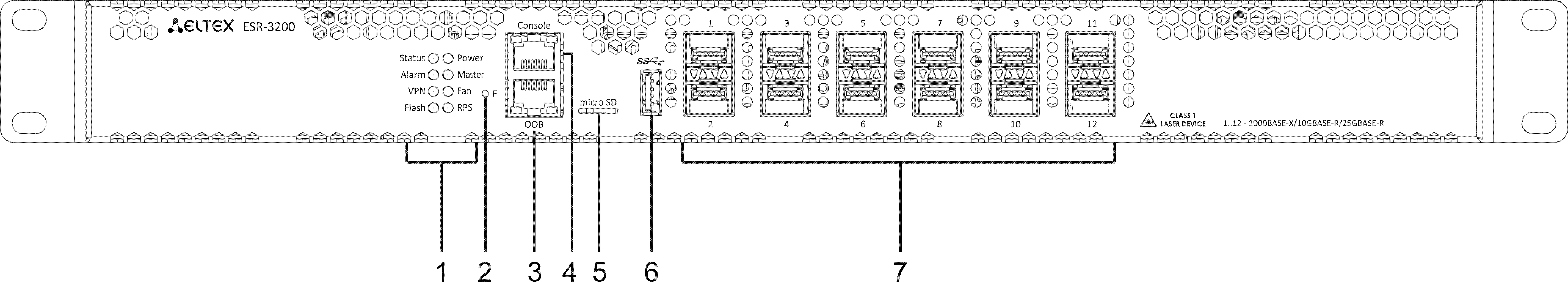
Figure 1 – ESR-3200 front panel
Table 9 lists connectors, LEDs and controls located on the front panel of ESR-3100.
Table 9 – Description of connectors, LEDs and controls located on ESR-3100 front panel
№ | Front panel element | Description |
|---|---|---|
1 | Status | Current device status LED. |
Alarm | Alarm LED. | |
VPN | VPN gateway operation mode LED. | |
Flash | Activity of exchange with data storage – SD card or USB Flash. | |
Power | Device power LED. | |
Master | Failover mode operation LED (is not supported in the current version). | |
Fan | Fan operation LED. | |
RPS | Redundant power supply LED. | |
2 | F | Functional key that reboots the device and resets it to factory default configuration:
|
| 3 | OOB | Ethernet port for router management. |
4 | Console | Console port RS-232 (RJ-45) for local management of the device. |
5 | microSD | microSD-card port. |
6 | USB1 | USB 2.0 port for USB devices connection. |
7 | [1 .. 12] | Slots for installing 25G SFP28/10G SFP+/1G SFP transceivers. |
ESR-3200 rear panel
The rear panel of ESR-3200 is depicted in Figure 2.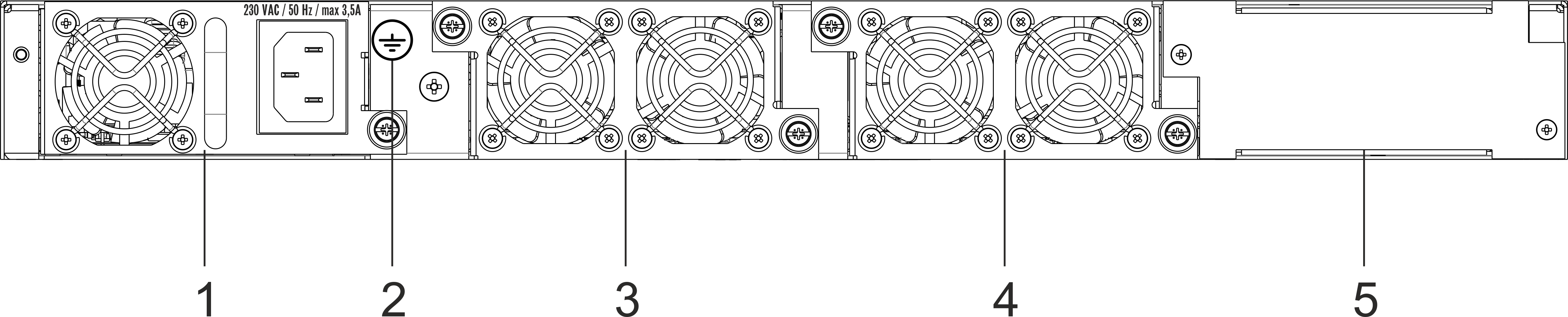
Figure 2 – ESR-3200 rear panel
Table 10 lists rear panel connectors of the router.
Table 10 – Rear panel connectors description
№ | Description |
|---|---|
1 | Main power supply. |
2 | Earth bonding point of the device. |
3 | Hot-swappable removable ventilation modules. |
4 | |
5 | Place for installation of a redundant power supply. |
ESR-3200 side panels
The side panel layout of ESR-3200 is depicted in figures 3 and 4.
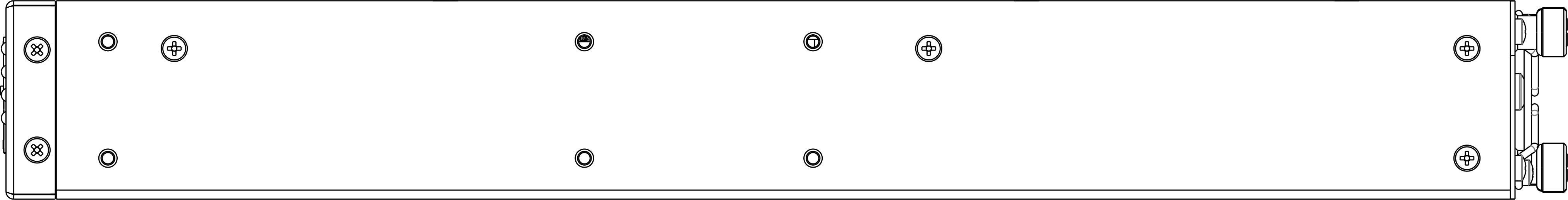
Figure 3 – ESR-3200 right side panel

Figure 4 – ESR-3200 left side panel
Side panels of the device have air vents for heat removal. Do not block air vents. This may cause the components to overheat, which may result in device malfunction. For recommendations on device installation, see section Installation and connection.
ESR-3100 design
ESR-3100 front panel
The front panel layout is depicted in 5.
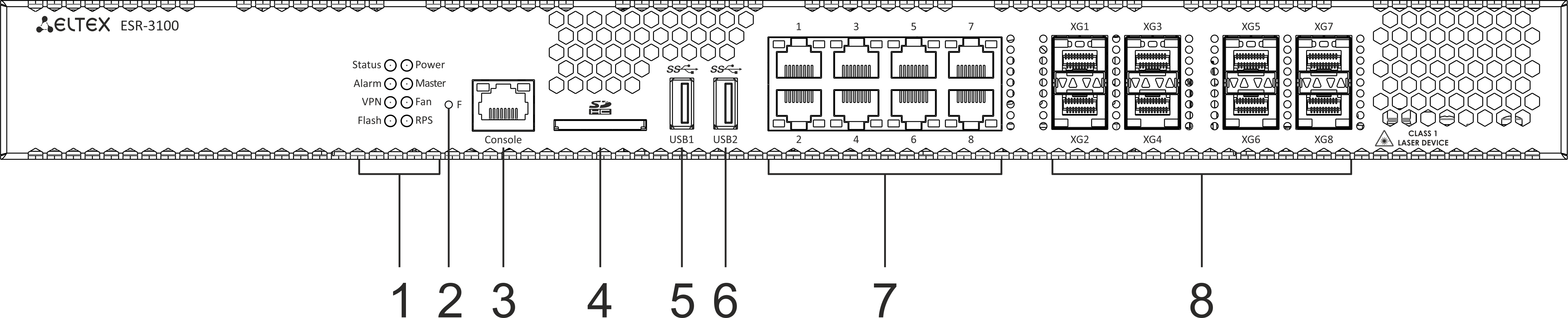
Figure 5 – ESR-3100 front panel
Table 11 lists connectors, LEDs and controls located on the front panel of ESR-3100.
Table 11 – Description of connectors, LEDs and controls located on ESR-3100 front panel
№ | Front panel element | Description |
|---|---|---|
1 | Status | Current device status LED. |
Alarm | Alarm LED. | |
VPN | VPN gateway operation mode LED. | |
Flash | Activity of exchange with data storage – SD card or USB Flash. | |
Power | Device power LED. | |
Master | Failover mode operation LED (is not supported in the current version). | |
Fan | Fan operation LED. | |
RPS | Redundant power supply LED. | |
2 | F | Functional key that reboots the device and resets it to factory default configuration:
|
3 | Console | Console port RS-232 (RJ-45) for local management of the device. |
4 | SD | SD-card connector. |
5 | USB1 | USB 3.0 port for USB device connection. |
6 | USB2 | USB 3.0 port for USB device connection. |
7 | [1 .. 8] | 8 ports of Gigabit Ethernet 10/100/1000BASE-T (RJ-45). |
8 | XG1 – XG8 | Slots for 10G SFP+/1G SFP transceivers. |
ESR-3100 rear panel
The rear panel of ESR-3100 is depicted in the figure below.
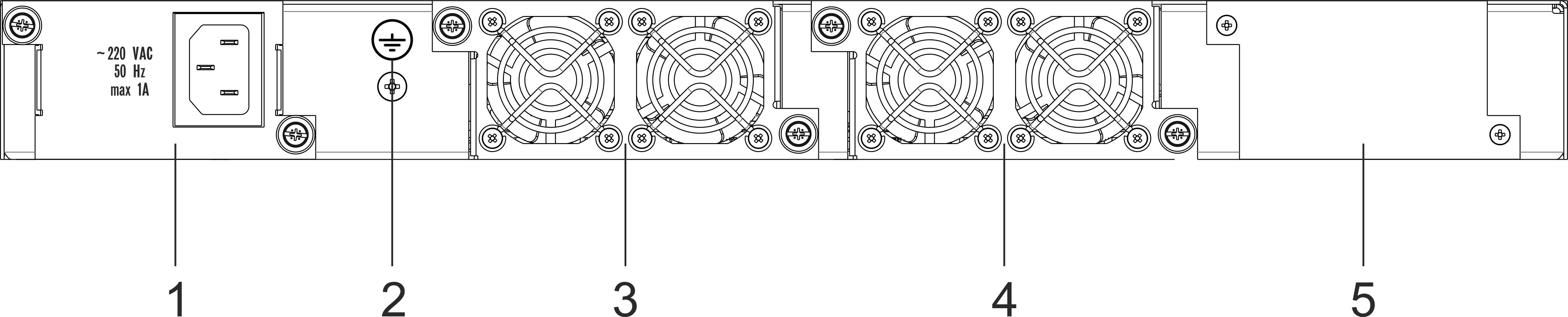
Figure 6 – ESR-3100 rear panel
Table 12 lists rear panel connectors of the router.
Table 12 – Rear panel connectors description
№ | Description |
|---|---|
1 | Main power supply. |
2 | Earth bonding point of the device. |
3 | Hot-swappable removable ventilation modules. |
4 | |
5 | Place for installation of a redundant power supply. |
ESR-3100 side panels
The side panel layout of ESR-3100 is depicted in figures 7 and 8.
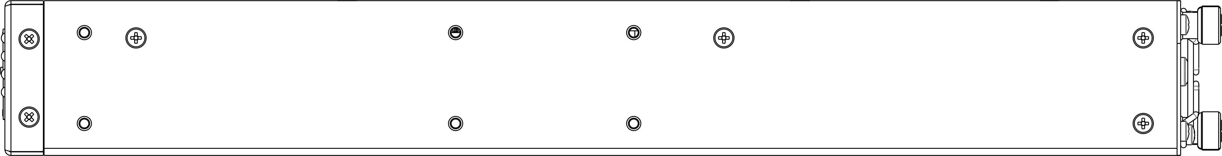
Figure 7 – ESR-3100 right side panel
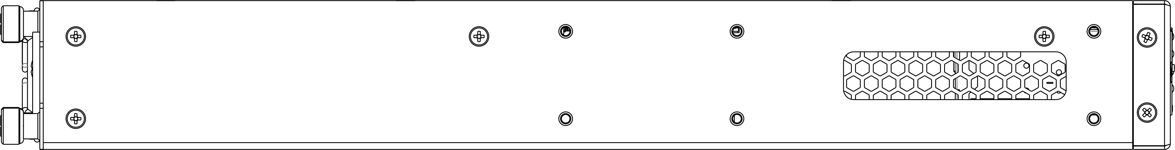
Figure 8 – ESR-3100 left side panel
Side panels of the device have air vents for heat removal. Do not block air vents. This may cause the components to overheat, which may result in device malfunction. For recommendations on device installation, see section Installation and connection.
ESR-1700 design
ESR-1700 front panel
The front panel layout is depicted in figure 9.
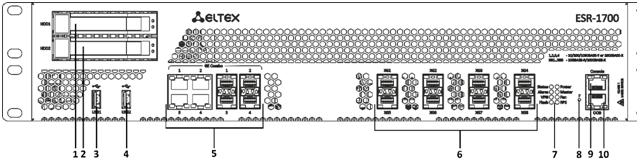
Figure 9 – ESR-1700 front panel
Table 13 lists connectors, LEDs and controls located on the front panel of ESR-1700.
Table 13 – Description of ESR-1700 connectors, LEDs and front panel controls
№ | Front panel element | Description |
|---|---|---|
1 | HDD1 | Connector for HDD installation. |
2 | HDD2 | Connector for HDD installation. |
3 | USB1 | Port for USB device connection. |
4 | USB2 | Port for USB device connection. |
5 | Combo Ports [1 .. 4] | 4 ports of Gigabit Ethernet 10/100/1000BASE-X (SFP). |
6 | XG1 – XG8 | Slots for 10G SFP+/1G SFP transceivers. |
7 | Status | Current device status LED. |
Alarm | Alarm LED. | |
VPN | VPN gateway operation mode LED (is not supported in the current version). | |
Flash | Activity of exchange with data storage – SD card or USB Flash. | |
Power | Device power LED. | |
Master | Failover mode operation LED (is not supported in the current version). | |
Fan | Fan operation LED. | |
RPS | Redundant power supply LED. | |
8 | F | Functional key that reboots the device and resets it to factory default configuration:
|
9 | Console | Console port RS-232 for local management of the device. |
10 | OOB | Ethernet port for router management. |
ESR-1700 rear panel
The rear panel of ESR-1700 is shown in the picture below.
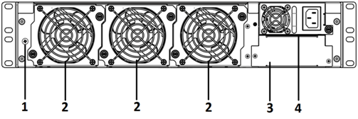
Figure 10 – ESR-1700 rear panel
Table 14 lists rear panel connectors of the router.
Table 14 – Rear panel connectors description
№ | Description |
|---|---|
1 | Earth bonding point of the device. |
2 | Hot-swappable removable ventilation modules. |
3 | Main power supply. |
4 | Place for installation of a redundant power supply. |
ESR-1700 side panels
The side panel layout of ESR-1700 is depicted in figures 3 and 4.
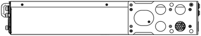
Figure 11 – ESR-1700 right side panel
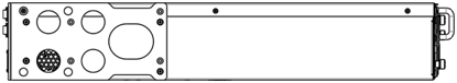
Figure 12 – ESR-1700 left side panel
Side panels of the device have air vents for heat removal. Do not block air vents. This may cause the components to overheat, which may result in device malfunction. For recommendations on device installation, see section Installation and connection.
ESR-1511, ESR-1510 design
ESR-1511 front panel
The front panel layout is depicted in figure 9.
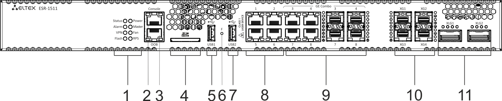
Figure 13 – ESR-1511 front panel
Table 15 lists connectors, LEDs and controls located on the front panel of ESR-1511.
Table 15 – Description of connectors, LEDs and controls located on ESR-1511 front panel
№ | Front panel element | Description |
|---|---|---|
1 | Status | Current device status LED. |
Alarm | Alarm LED. | |
VPN | VPN gateway operation mode LED (is not supported in the current version). | |
Flash | Activity of exchange with data storage – SD card or USB Flash. | |
Power | Device power LED. | |
Master | Failover mode operation LED (is not supported in the current version). | |
Fan | Fan operation LED. | |
RPS | Redundant power supply LED. | |
2 | Console | Console port RS-232 for local management of the device. |
3 | OOB | Ethernet port for router management. |
4 | SD | SD-card connector. |
5 | USB1 | Port for USB device connection. |
6 | F | Functional key that reboots the device and resets it to factory default configuration:
|
7 | USB2 | Port for USB device connection. |
8 | Ethernet | 4 ports of Ethernet 10/100/1000BASE-T. |
9 | Combo Ports [1 .. 4] | 4 ports of Gigabit Ethernet 10/100/1000BASE-X (SFP). |
10 | XG1 – XG4 | Slots for 10G SFP+/1G SFP transceivers. |
11 | XLG1 – XLG2 | Slots for 40G QSFP+ transceivers. |
ESR-1500 front panel
The front panel layout is depicted in figure 14.

Figure 14 – ESR-1500 front panel
Table 16 lists connectors, LEDs and controls located on the front panel of ESR-1500.
Table 16 – Description of ESR-1500 connectors, LEDs and front panel controls
№ | Front panel element | Description |
|---|---|---|
1 | Status | Current device status LED. |
Alarm | Alarm LED. | |
VPN | VPN gateway operation mode LED (is not supported in the current version). | |
Flash | Activity of exchange with data storage – SD card or USB Flash. | |
Power | Device power LED. | |
Master | Failover mode operation LED (is not supported in the current version). | |
Fan | Fan operation LED. | |
RPS | Redundant power supply LED. | |
2 | Console | Console port RS-232 for local management of the device. |
3 | OOB | Ethernet port for router management. |
4 | SD | SD-card connector. |
5 | USB1 | Port for USB device connection. |
6 | F | Functional key that reboots the device and resets it to factory default configuration:
|
7 | USB2 | Port for USB device connection. |
8 | Ethernet | 4 ports of Ethernet 10/100/1000BASE-T. |
9 | Combo Ports [1 .. 4] | 4 ports of Gigabit Ethernet 10/100/1000BASE-X (SFP). |
10 | XG1 – XG4 | Slots for 10G SFP+/1G SFP transceivers. |
ESR-1511, ESR-1500 rear panel
The rear panel layout of ESR-1511 and ESR-1500 routers is depicted in figure 15.
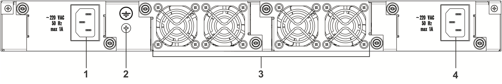
Figure 15 – ESR-1511, ESR-1500 rear panel
Table 17 lists rear panel connectors of the router.
Table 17 – Rear panel connectors description
№ | Description |
|---|---|
1 | Main power supply. |
2 | Earth bonding point of the device. |
3 | Hot-swappable removable ventilation modules. |
4 | Place for installation of a redundant power supply. |
ESR-1511, ESR-1500 side panels
The side panel layout of ESR-1511, ESR-1500 is depicted in Figures 16 and 17.
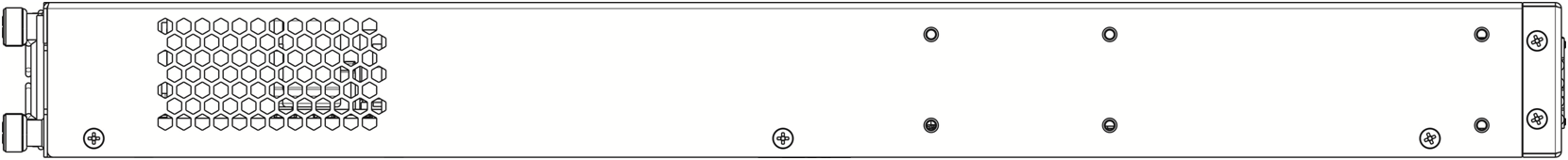
Figure 16 – ESR-1511, ESR-1500 right side panel
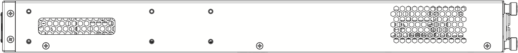
Figure 17 – ESR-1511, ESR-1500 left side panel
Side panels of the device have air vents for heat removal. Do not block air vents. This may cause the components to overheat, which may result in device malfunction. For recommendations on device installation, see section Installation and connection.
ESR-1200, ESR-1000 design
ESR-1200 front panel
The front panel layout is depicted in 18.
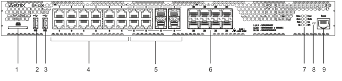
Figure 18 – ESR-1200 front panel
Table 18 lists connectors, LEDs and controls located on the front panel of ESR-1200.
Table 18 – Description of connectors, LEDs and controls located on the front panel of ESR-1200
№ | Front panel element | Description |
|---|---|---|
1 | SD | SD-card connector. |
2 | USB1 | Port for USB device connection. |
3 | USB2 | Port for USB device connection. |
4 | [1 .. 12] | 12 ports of Gigabit Ethernet 10/100/1000BASE-T (RJ-45). |
5 | Combo Ports | 4 ports of Gigabit Ethernet 10/100/1000BASE-X (SFP). |
6 | XG1 – XG8 | Slots for installation of 10G SFP+/1G SFP transceivers. |
7 | Status | Current device status LED. |
Alarm | Alarm LED. | |
HA | HA operation mode LED. | |
Flash | Activity indicator of exchange with data storages (SD-card or USB Flash). | |
Power | Device power LED. | |
Master | Indicator of failover modes operation. | |
Fan | Fan operation LED. | |
RPS | Redundant power supply LED. | |
8 | F | Functional key that reboots the device and resets it to factory default configuration:
|
9 | Console | Console port RS-232 for local management of the device. |
ESR-1000 front panel
The front panel layout is depicted in 19.
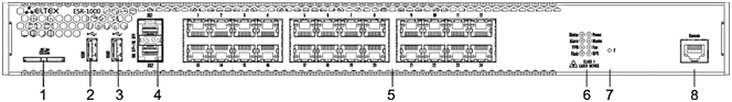
Figure 19 – ESR-1000 front panel
Table 19 lists sizes, LEDs and controls located on ESR-1000 front panel.
Table 19 – Description of connectors, LEDs and controls located on ESR-1000 front panel
№ | Front panel element | Description |
|---|---|---|
1 | SD | SD-card connector. |
2 | USB1 | Port for USB device connection. |
3 | USB2 | Port for USB device connection. |
4 | XG1, XG2 | Slots for 10G SFP+/1G SFP transceivers. |
5 | [1 .. 24] | 24 ports of Gigabit Ethernet 10/100/1000BASE-T (RJ-45). |
6 | Status | Current device status LED. |
Alarm | Alarm LED. | |
VPN | Active VPN sessions indicator. | |
Flash | Activity indicator of exchange with data storages (SD-card or USB Flash). | |
Power | Device power LED. | |
Master | Indicator of failover modes operation. | |
Fan | Fan operation LED. | |
RPS | Redundant power supply LED. | |
7 | F | Functional key that reboots the device and resets it to factory default configuration:
|
8 | Console | Console port RS-232 for local management of the device. |
ESR-1200, 1000 rear panel
The rear panel of ESR-1000 is depicted in the figure below.
The figure shows the router delivery package with a single AC power supply.
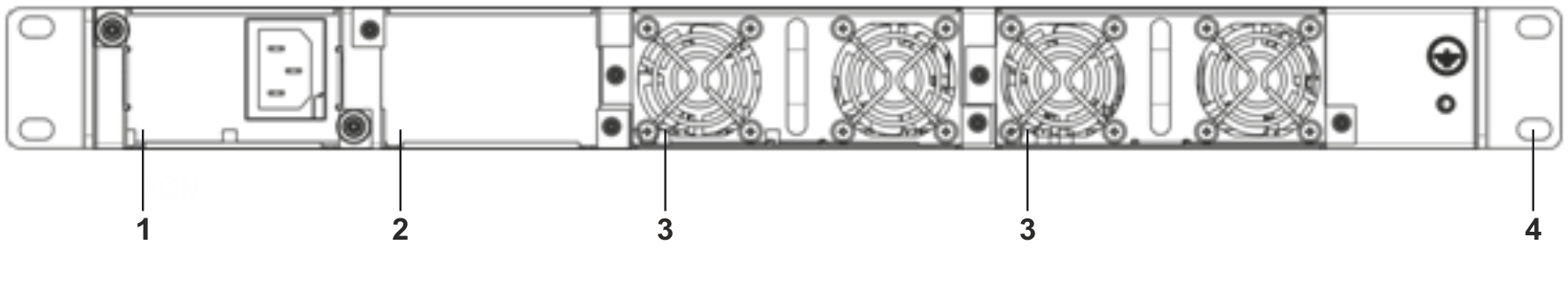
Figure 20 – ESR-1000 rear panel
Table 20 lists rear panel connectors of the router.
Table 20 – Rear panel connectors description
№ | Description |
|---|---|
1 | Main power supply. |
2 | Place for installation of a redundant power supply. |
3 | Hot-swappable removable ventilation modules. |
4 | Earth bonding point of the device. |
ESR-1200, ESR-1000 side panels
The side panel layout of ESR-1200, ESR-1000 is depicted in Figures 21 and 22.
Figure 21 – ESR-1200, 1000 right side panel
Figure 22 – ESR-1200, 1000 left side panel
Side panels of the device have air vents for heat removal. Do not block air vents. This may cause the components to overheat, which may result in device malfunction. For recommendations on device installation, see section Installation and connection.
ESR-200, ESR-100 design
ESR-100, ESR-200 front panel
The front panel layout of ESR-200 is depicted in figure 23.
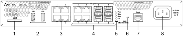
Figure 23 – ESR-200 front panel
The front panel layout of ESR-100 is depicted in figure 24.
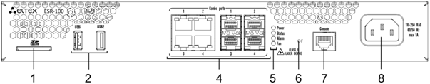
Figure 24 – ESR-100 front panel
Table 21 lists connectors, LEDs and controls located on the front panel of ESR-100 and ESR-200 routers.
Table 21 – Description of connectors, LEDs and controls located on ESR-200, ESR-100 front panel
№ | Front panel element | Description |
|---|---|---|
1 | SD | SD-card connector. |
2 | USB1, USB2 | 2 × USB-enabled devices connection port. |
3 | [1 .. 4] | 4 ports of Gigabit Ethernet 10/100/1000BASE-T (RJ-45). |
4 | Combo Ports | 4 ports of Gigabit Ethernet 10/100/1000BASE-X (SFP). |
5 | Power | Device power LED. |
Status | Current device status LED. | |
Alarm | Alarm LED. | |
Fan | Fan operation LED. | |
6 | F | Functional key that reboots the device and resets it to factory default configuration:
|
7 | Console | Console port RS-232 for local management of the device. |
8 | 110-250 VAC | Power supply. |
ESR-200, ESR-100 rear panel
The rear panel layout of ESR-200 and ESR-100 routers is depicted in figure 25.
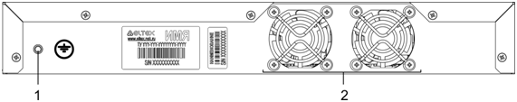
Figure 25 – ESR-200, ESR-100 rear panel
Table 22 lists rear panel connectors of the router.
Table 22 – Rear panel connectors description
№ | Description |
|---|---|
1 | Earth bonding point of the device. |
2 | Ventilation module. |
ESR-100, ESR-200 side panels
The side panel layout of ESR-200, ESR-100 is depicted in Figures 26 and 27.
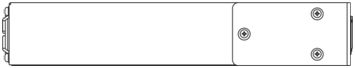
Figure 26 – ESR-100 and ESR-200 right side panel
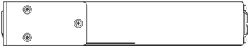
Figure 27 – ESR-100 and ESR-200 left side panel
ESR-21 design
The device has a metal-enclosed design for 1U 19" racks.
ESR-21 front panel
The front panel layout of ESR-21 is depicted in figure 28.
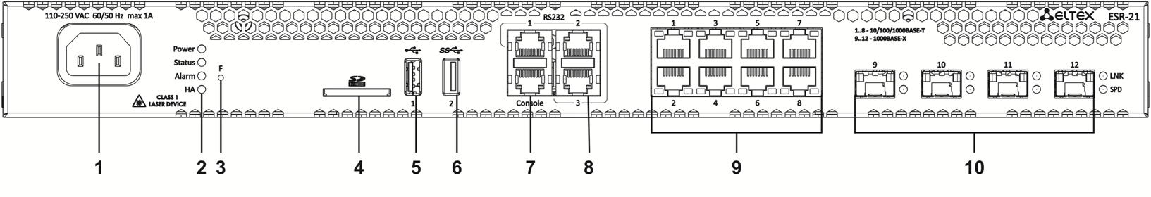
Figure 28 – ESR-21 front panel
Table 23 lists sizes, LEDs and controls located on ESR-21 front panel.
Table 23 – Description of connectors, LEDs and controls located on ESR-21 front panel
№ | Front panel element | Description |
|---|---|---|
1 | 220V AC | Power supply |
2 | Power | Device power LED |
Status | Device status LED | |
Alarm | Device alarm presence and level LED | |
HA | HA operation mode LED (is not supported in the current version) | |
3 | F | Functional key that reboots the device and resets it to factory default configuration: - pressing the key for less than 10 seconds reboots the device. – pressing the key for more than 10 seconds resets the device to factory default configuration. |
4 | SD | SD-card connector |
5 | USB1 | USB 2.0 connector for connecting external USB devices |
6 | USB2 | USB 3.0 connector for connecting external USB devices |
7 | Console | Console port for local management of the device |
8 | RS-232 | 3 serial ports |
9 | [1 .. 8] | 8 ports of Gigabit Ethernet 10/100/1000BASE-T (RJ-45) |
10 | Optical Port | 4 ports of Gigabit Ethernet 10/100/1000BASE-X (SFP) |
ESR-21 rear panel
The rear panel layout of ESR-21 is depicted in figure 29.
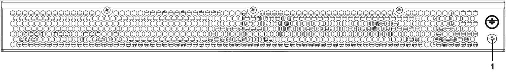
Figure 29 – ESR-21 rear panel
Table 24 lists rear panel connectors of the router.
Table 24 – Rear panel connectors description
№ | Description |
|---|---|
1 | Earth bonding point of the device. |
ESR-21 side panels
The side panel layout of ESR-21 is depicted in figures 30 and 31.
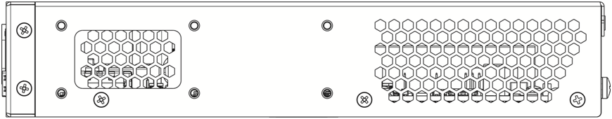
Figure 30 – ESR-21 left side panel
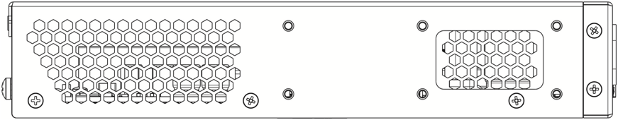
Figure 31 – ESR-21 right side panel
Side panels of the device have air vents for heat removal. Do not block air vents. This may cause the components to overheat, which may result in device malfunction. For recommendations on device installation, see section Installation and connection.
ESR-30, ESR-20 design
The device has a metal-enclosed design for 1U 19" racks.
ESR-30 front panel
The front panel layout is depicted in figure 32.
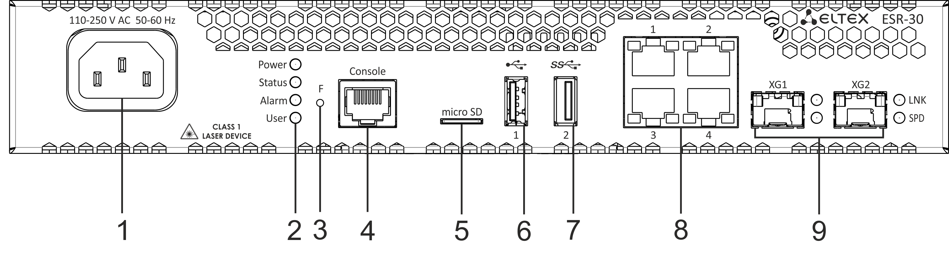
Figure 32 – ESR-20 front panel
Table 25 lists connectors, LEDs and controls located on the front panel of ESR-30.
Table 25 – Description of connectors, LEDs and controls located on ESR-30 front panel
№ | Front panel element | Description |
|---|---|---|
1 | 110-250 VAC | Power supply. |
2 | Power | Device power LED. |
Status | Current device status LED. | |
Alarm | Alarm LED. | |
User | LED for custom scenarios that can be assigned in device configuration mode. | |
3 | F | Functional key that reboots the device and resets it to factory default configuration: - pressing the key for less than 10 seconds reboots the device. – pressing the key for more than 10 seconds resets the device to factory default configuration. |
4 | Console | Console port RS-232 (RJ-45) for local management of the device. |
5 | microSD | microSD-card connector. |
6 | USB1 | USB 2.0 connector for connecting external USB devices. |
7 | USB2 | USB 3.0 connector for connecting external USB devices. |
| 8 | [1 .. 4] | 4 ports of 10/100/1000BASE-T. |
9 | 1, 2 | 2 ports of10GBASE-R (SPF+)/1000BASE-X. |
ESR-20 front panel
The front panel layout is depicted in figure 33.
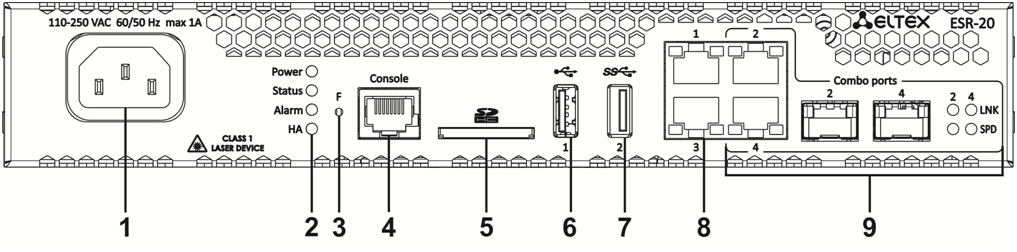
Figure 33 – ESR-20 front panel
Table 26 lists connectors, LEDs and controls located on the front panel of ESR-20.
Table 26 – Description of connectors, LEDs and controls located on ESR-20 front panel
№ | Front panel element | Description |
|---|---|---|
1 | 110-250 VAC | Power supply. |
2 | Power | Device power LED. |
Status | Current device status LED. | |
Alarm | Alarm LED. | |
HA | HA operation mode LED (is not supported in the current version). | |
3 | F | Functional key that reboots the device and resets it to factory default configuration: - pressing the key for less than 10 seconds reboots the device. – pressing the key for more than 10 seconds resets the device to factory default configuration. |
4 | Console | Console port RS-232 (RJ-45) for local management of the device. |
5 | SD | SD-card connector. |
6 | USB1 | USB 2.0 connector for connecting external USB devices. |
7 | USB2 | USB 3.0 connector for connecting external USB devices. |
8 | 1, 2 | 2 ports of Gigabit Ethernet 10/100/1000BASE-T (RJ-45). |
9 | [1 .. 4] | 2 Combo ports of Ethernet 10/100/1000BASE-X/10/100/1000BASE-T. |
ESR-20, ESR-30 rear panel
The rear panel layout of ESR-20 and ESR-30 is depicted in figure 34.
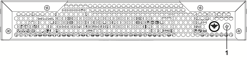
Figure 34 – ESR-20, ESR-30 rear panel
Table 27 lists rear panel connectors of the routers.
Table 27 – Rear panel connectors description
№ | Description |
|---|---|
1 | Earth bonding point of the device. |
ESR-20, ESR-30 side panels
The side panel layout of ESR-20 and ESR-30 is depicted in figures 35 and 36.
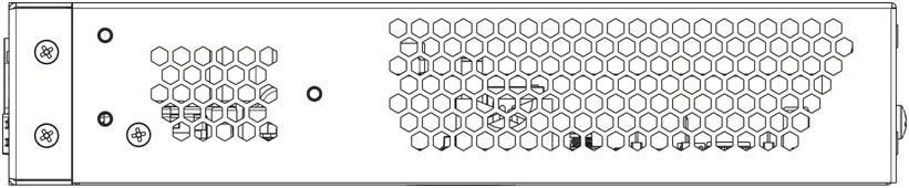
Figure 35 – ESR-20, ESR-30 left side panel
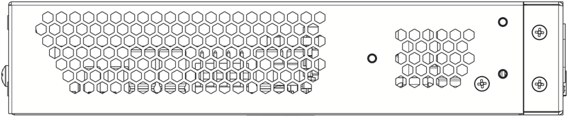
Figure 36 – ESR-20, ESR-30 right side panel
Side panels of the device have air vents for heat removal. Do not block air vents. This may cause the components to overheat, which may result in device malfunction. For recommendations on device installation, see section Installation and connection.
ESR-15 design
The device has a metal-enclosed design for 1U 19" racks.
ESR-15 front panel
The front panel layout is depicted in figure 37.
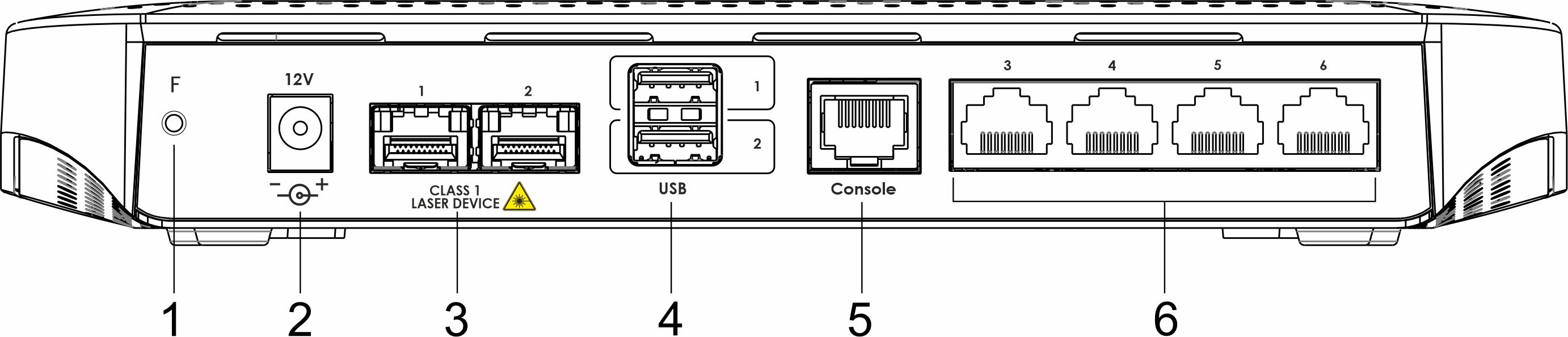
Figure 37 – ESR-15 front panel
Table 28 lists connectors, LEDs and controls located on the front panel of ESR-15 router.
Table 28 – Description of connectors, LEDs and controls located on ESR-15 front panel
№ | Front panel element | Description |
|---|---|---|
| 1 | F | Functional key that reboots the device and resets it to factory default configuration:
|
| 2 | 12V DC | Power supply. |
| 3 | Optical ports | 2 ports of Gigabit Ethernet – 1000BASE-X (SFP). |
| 4 | USB1, USB2 | 2 USB connectors for connecting external USB devices. |
3 | Console | Console port RS-232 (RJ-45) for local management of the device. |
9 | [1 .. 4] | 4 ports of Gigabit Ethernet 10/100/1000BASE-T (RJ-45). |
ESR-15 top panel
The top panel layout of ESR-10 is depicted in figure 38.
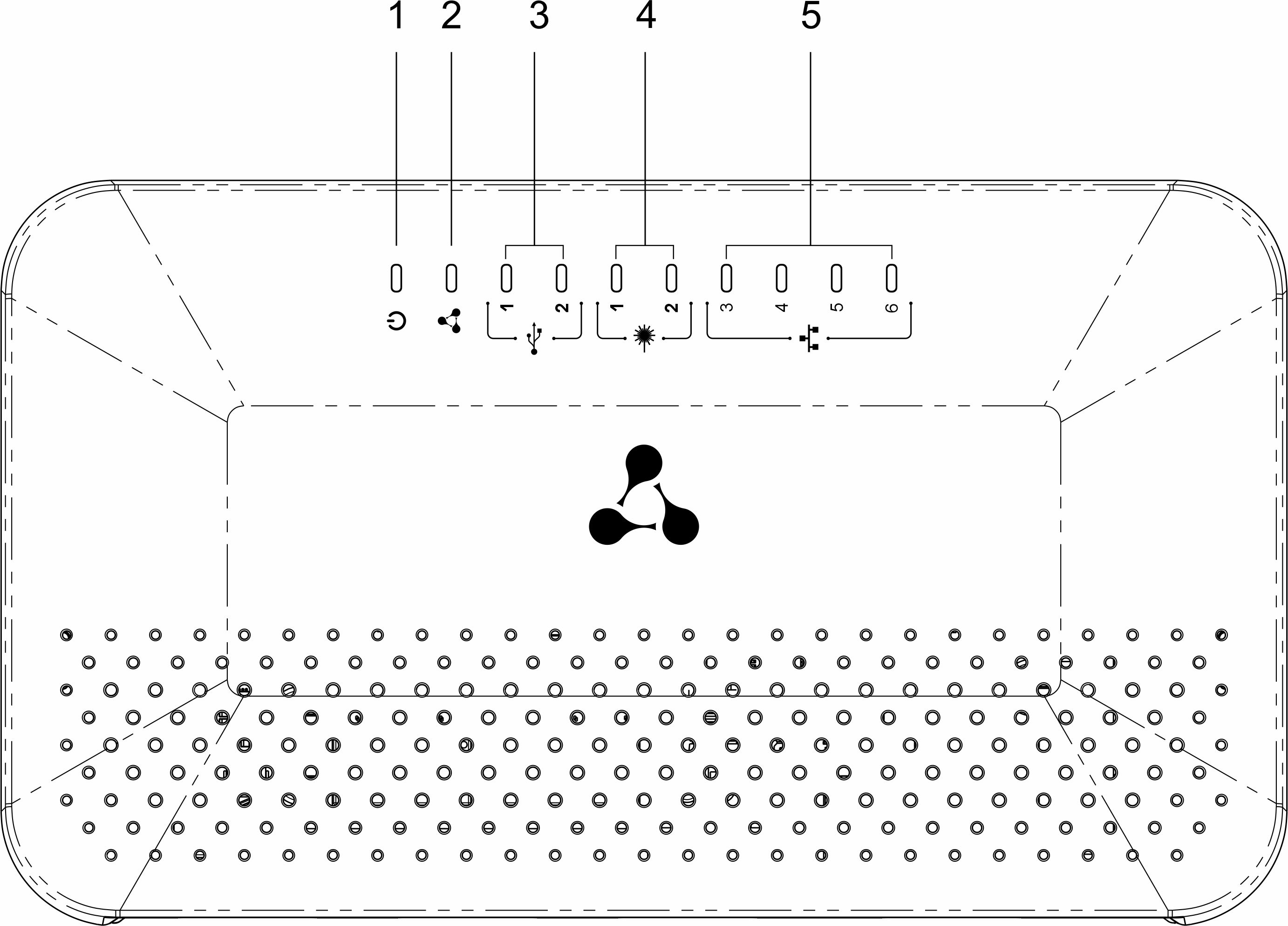
Table 29 lists LEDs located on ESR-15 top panel.
Table 29 – Description of front panel LEDs
№ | Top panel element | Description |
|---|---|---|
1 | Power | Device power and operation status LED |
2 | - | The LED is not used |
3 | USB1, USB2 | External USB devices LED |
4 | [1 .. 2] | Ethernet ports LED |
5 | [3 .. 6] | Optical interfaces LED |
ESR-14VF, ESR-12VF design
The device has a metal-enclosed design for 1U 19" racks.
ESR-14VF, ESR-12VF front panel
The front panel layout is depicted in figure 39.
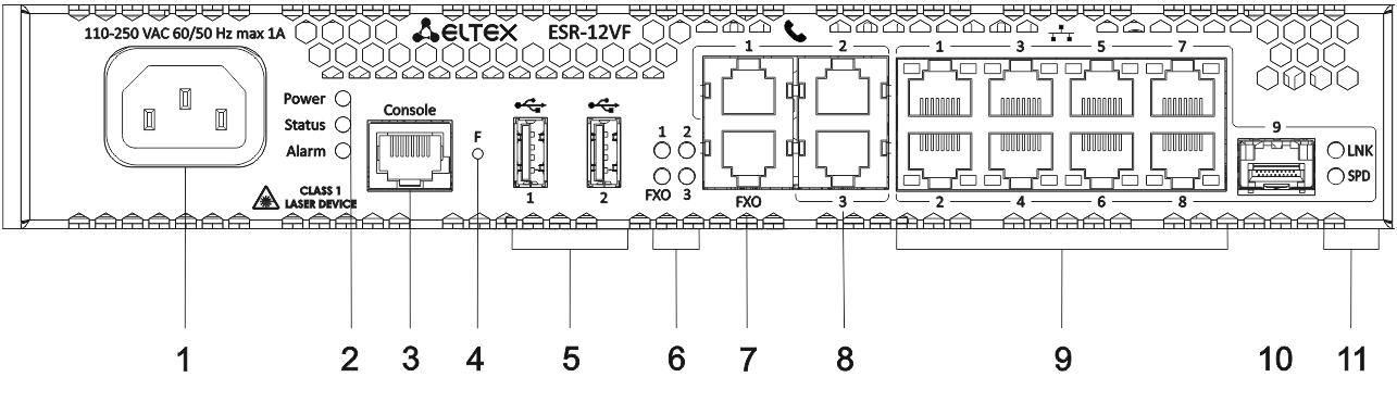
Figure 39 – ESR-14VF, ESR-12VF front panel
Table 30 lists connectors, LEDs and controls located on the front panel of ESR-14VF and ESR-12VF routers.
Table 30 – Description of connectors, LEDs and controls located on ESR-14VF, ESR-12VF front panel
№ | Front panel element | Description |
|---|---|---|
1 | 220V AC | Power supply. |
2 | Power | Device power LED. |
3 | Console | Console port RS-232 (RJ-45) for local management of the device. |
4 | F | Functional key that reboots the device and resets it to factory default configuration: - pressing the key for less than 10 seconds reboots the device. – pressing the key for more than 10 seconds resets the device to factory default configuration. |
5 | USB1, USB2 | 2 USB connectors for connecting external USB devices. |
6 | FXO | PSTN external subscriber line LED. |
1,2,3 | Internal subscriber terminals LED. | |
7 | FXO | 1 FXO connector for connection PSTN external subscriber line (only for ESR-12VF). |
8 | FXS 1, FXS 2, FXS 3 | 3 connectors for internal subscriber terminals (for ESR-12VF). |
FXS 1, FXS 2, FXS 3 | 4 connectors for internal subscriber terminals (for ESR-14VF). | |
9 | [1 .. 8] | 8 ports of Gigabit Ethernet 10/100/1000BASE-T (RJ-45). |
10 | Optical Port | 1 port of Gigabit Ethernet-100/1000BASE-X (SFP). |
11 | 1,2 | Optical interfaces LED. |
ESR-14VF, ESR-12VF rear panel
The rear panel layout of ESR-12VF, ESR-14-VF is depicted in figure 40.
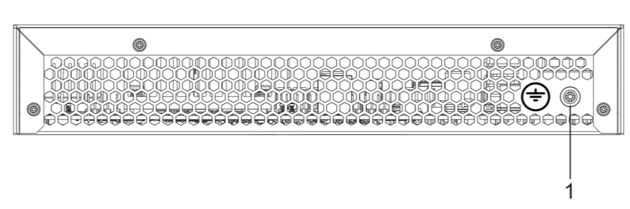
Figure 40 – ESR-12VF, ESR-14VF rear panel
Table 31 lists rear panel connectors of the router.
Table 31 – Rear panel connectors description
№ | Description |
|---|---|
1 | Earth bonding point of the device. |
ESR-12VF, ESR-14VF side panels
The side panel layout of ESR-12VF, ESR-14VF is depicted in Figures 41 and 42.
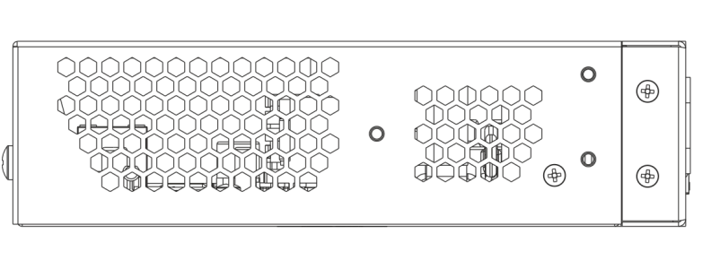
Figure 41 – ESR-12VF, ESR-14VF left side panel

Figure 42 – ESR-12VF, ESR-14VF right side panel
Side panels of the device have air vents for heat removal. Do not block air vents. This may cause the components to overheat, which may result in device malfunction. For recommendations on device installation, see section Installation and connection.
ESR-12V design
The device has a metal-enclosed design for 1U 19" racks.
ESR-12V front panel
The front panel layout is depicted in figure 43.
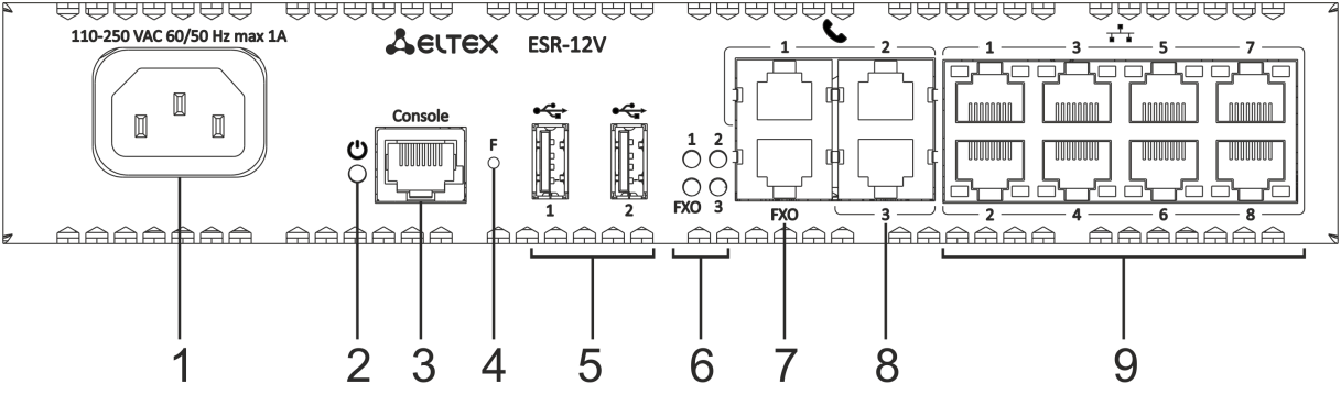
Figure 43 – ESR-12V front panel
Table 32 lists connectors, LEDs and controls located on the front panel of ESR-12VF router.
Table 32 – Description of connectors, LEDs and controls located on ESR-12V front panel
№ | Front panel element | Description |
|---|---|---|
1 | 220V AC | Power supply. |
2 | Power | Device power LED. |
3 | Console | Console port RS-232 (RJ-45) for local management of the device. |
4 | F | Functional key that reboots the device and resets it to factory default configuration: - pressing the key for less than 10 seconds reboots the device. – pressing the key for more than 10 seconds resets the device to factory default configuration. |
5 | USB1, USB2 | 2 USB connectors for connecting external USB devices. |
6 | FXO | PSTN external subscriber line LED. |
1,2,3 | Internal subscriber terminals LED. | |
7 | FXO | 1 FXO connector for connection PSTN external subscriber line. |
8 | FXS 1, FXS 2, FXS 3 | 3 connectors for internal subscriber terminals. |
9 | [1 .. 8] | 8 ports of Gigabit Ethernet 10/100/1000BASE-T (RJ-45). |
ESR-12V rear panel
The rear panel layout of ESR-12V is depicted in 44.

Figure 44 – ESR-12V rear panel
Table 33 lists rear panel connectors of the router.
Table 33 – Rear panel connectors description
№ | Description |
|---|---|
1 | Earth bonding point of the device. |
ESR-12V side panels
The side panel layout of ESR-12V is depicted in figures 45 and 46.

Figure 45 – ESR-12V left side panel
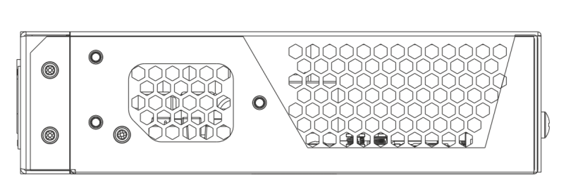
Figure 46 – ESR-12V right side panel
Side panels of the device have air vents for heat removal. Do not block air vents. This may cause the components to overheat, which may result in device malfunction. For recommendations on device installation, see section Installation and connection.
ESR-10 design
ESR-10 rear panel
The rear panel layout of the device is depicted in figure 47.
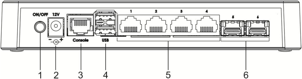
Figure 47 – ESR-10 rear panel
Table 34 lists connectors, LEDs and controls located on the rear panel of ESR-10.
Table 34 – Description of connectors, LEDs and controls located on ESR-10 rear panel
№ | Front panel element | Description |
|---|---|---|
1 | ON/OFF | Power on/off button. |
2 | 12V DC | Connector for power adapter connection. |
3 | Console | Console port RS-232 (RJ-45) for local management of the device. |
4 | USB1, USB2 | 2 USB connectors for connecting external USB devices. |
5 | [1.. 4] | 4 ports of Gigabit Ethernet – 10/100/1000BASE-T (RJ-45). |
6 | Optical Ports | 2 ports of Gigabit Ethernet-100/1000BASE-X (SFP). |
ESR-10 side panels
The side panel layout of ESR-10 is depicted in figure 48.
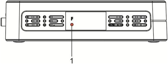
Figure 48 – ESR-10 side panel
Table 35 lists right panel controls of the router.
Table 35 – Right panel connectors description
№ | Side panel element | Description |
|---|---|---|
1 | F | Functional key that reboots the device and resets it to factory default configuration:
|
ESR-10 top panel
The top panel layout of ESR-10 is depicted in figure 49.
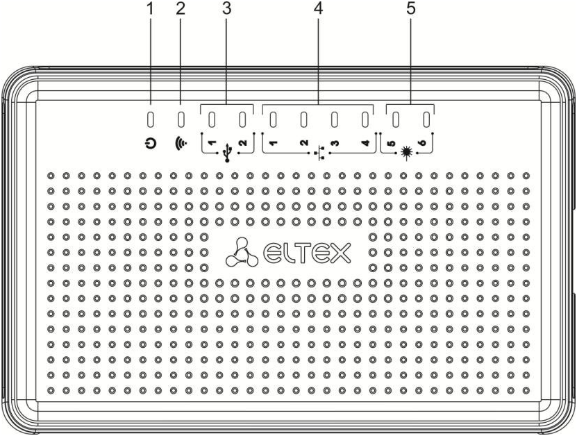
Figure 49 – ESR-10 top panel
Table 36 lists LEDs located on ESR-10 top panel.
Table 36 – Description of front panel LEDs
№ | Top panel element | Description |
|---|---|---|
1 | Power | Device power and operation status LED. |
2 | - | The LED is not used. |
3 | USB1, USB2 | External USB devices LED. |
4 | [1 .. 4] | Ethernet ports LED. |
5 | [5 .. 6] | Optical interfaces LED. |
Light Indication
ESR-1700, ESR-1200, ESR-1000 light indication
Gigabit Ethernet copper interface statuses are represented by two LEDs – green LINK/ACT LED and amber SPEED LED. Location of the copper interface LEDs is depicted in figure 50. SFP interface status is represented by two LEDs – RX/ACT and TX/ACT – depicted in figure 51. For light indication meaning, see Tables 37 and 38 respectively.
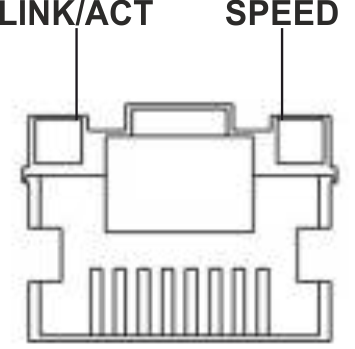
Figure 50 – Location of RJ-45 connector indicators
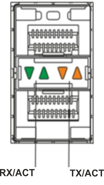
Figure 51 – Location of optical interface indicators
Table 37 – Light indication of copper interface status
SPEED indicator is lit | LINK/ACT indicator is lit | Ethernet interface state |
|---|---|---|
Off | Off | The port is disabled or connection is not established. |
Off | Solid on | 10Mbps or 100Mbps connection is established. |
Solid on | Solid on | 1000Mbps connection is established. |
X | Flashes | Data transfer is in progress. |
Table 38 – Light indication of SFP/SFP+/QSFP+ interface status
RX/ACT indicator is lit | TX/ACT indicator is lit | Ethernet interface state |
|---|---|---|
Off | Off | The port is disabled or connection is not established. |
Solid on | Solid on | Connection established. |
Flashes | X | Data reception in progress. |
X | Flashes | Data transfer is in progress. |
The following table lists description of system indicator statuses and meanings.
Table 39 – Status of system indicators
Indicator name | Indicator function | LED State | Device State |
|---|---|---|---|
Status | Current device status LED. | Green | Device is in normal operation state. |
Red | The device is in the firmware download state. | ||
Alarm | Alarm LED. | - | - |
VPN | Active VPN sessions indicator. | - | - |
Flash | Activity indicator of exchange with data storages: SD-card or USB Flash. | Green | Read/write operation execution with 'copy' command. |
Power | Device power LED. | Green | Device power is normal. Main power supply, if installed, is operational. |
Orange | Main power supply failure, fault, or the primary network is missing. | ||
Off | Device internal power supply failure. | ||
Master | Indicator of failover modes operation. | - | - |
Fan | Cooling fan status. | Off | All fans are operational. |
Red | One or more fans has failed. Possible cause of failure: at least one of the fans has stopped or is working at lower rpm. | ||
RPS | Backup power supply operation mode. | Green | Backup power supply is installed and operational. |
Off | Backup power supply is not installed. | ||
Red | Backup power supply is missing or failed. |
ESR-3200, ESR-3100, ESR-1511, ESR-1500 light indication
Gigabit Ethernet copper interface and SFP interface statuses are represented by two LEDs – green LINK/ACT LED and amber SPEED LED. Location of the copper interface LEDs is depicted in figure 52. SFP interface status is depicted in figure 53. For light indication meaning, see Tables 40 and 41 respectively.
Figure 52 – Location of RJ-45 connector indicators
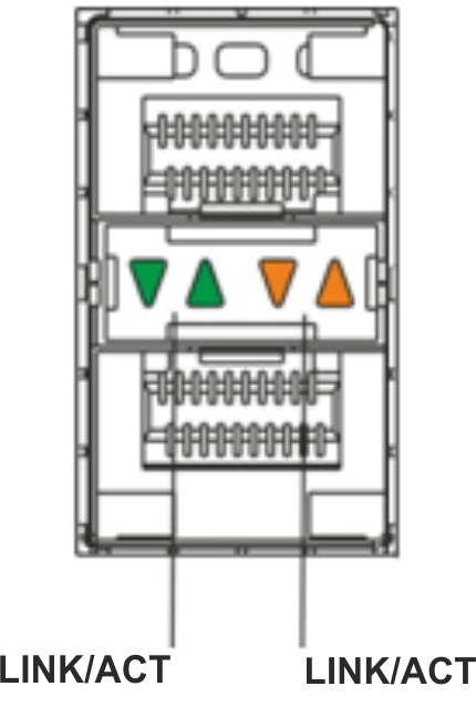
Figure 53 – Location of optical interface indicators
Table 40 – Light indication of copper interfaces status
SPEED indicator is lit | LINK/ACT indicator is lit | Ethernet interface state |
|---|---|---|
Off | Off | The port is disabled or connection is not established. |
Off | Solid on | 10 Mbps or 100 Mbps connection is established. |
Solid on | Solid on | 1000 Mbps connection is established. |
X | Flashes | Data transfer is in progress. |
Table 41 – Light indication of SFP/SFP+/QSFP+ status
SPEED indicator is lit | LINK/ACT indicator is lit | Ethernet interface state |
|---|---|---|
Off | Off | The port is disabled or connection is not established. |
Solid on | Solid on | Connection is established. |
Flashes | X | Data reception is in progress. |
X | Flashes | Data transfer is in progress. |
The following table describes the states of the system LEDs on the device and their meanings.
Table 42 – Status of system indicators
Indicator name | Indicator function | LED State | Device State |
|---|---|---|---|
Status | Current device status LED. | Green | Device is in normal operation state. |
Orange | Device is booting up the software. | ||
Alarm | Device alarm presence and level indicator. | - | - |
| VPN | Active VPN sessions indicator. | - | - |
| Flash | Activity indicator of exchange with data storages: SD-card or USB Flash. | Orange | Read/write operation execution with 'copy' command. |
Power | Device power LED. | Green | Device power is OK. Main power supply, if installed, is operational. |
Orange | Main power supply failure, fault, or the primary network is missing. | ||
Off | Device internal power supply failure. | ||
| Master | Indicator of failover modes operation. | - | - |
Fan | Cooling fan status. | Off | All fans are operational. |
Red | One or more fans has failed. Possible cause of failure: at least one of the fans has stopped or is working at lower rpm. | ||
| RPS | Backup power supply operation mode. | Green | Backup power supply is installed and operational. |
| Off | Backup power supply is not installed. | ||
| Red | Backup power supply is missing or failed. |
ESR-200/ESR-100 light indication
Gigabit Ethernet copper interface and SFP interface statuses are represented by two LEDs – green LINK/ACT LED and amber SPEED LED. Location of the copper interface LEDs is depicted in figure 50. SFP interface status is depicted in figure 54. For light indication meaning, see Table 43.
Figure 54 – Location of optical interface indicators
Table 43 – Light indication of copper and SFP interfaces status
SPEED indicator is lit | LINK/ACT indicator is lit | Ethernet interface state |
|---|---|---|
Off | Off | The port is disabled or connection is not established. |
Off | Solid on | 10 Mbps or 100 Mbps connection is established. |
Solid on | Solid on | 1000 Mbps connection is established. |
X | Flashes | Data transfer is in progress. |
The following table describes the states of the system LEDs on the device and their meanings.
Table 44 – Status of system indicators
Indicator name | Indicator function | LED State | Device State |
|---|---|---|---|
Status | Current device status LED. | Green | Device is in normal operation state. |
Red | Device is booting up the software. | ||
Alarm | Device alarm presence and level indicator1. | - | - |
Power | Device power LED. | Green | Device power is OK. Main power supply, if installed, is operational. |
Red | Main power supply failure, fault, or the primary network is missing. | ||
Off | Device internal power supply failure. | ||
Fan | Cooling fan status. | Off | All fans are operational. |
Red | One or more fans has failed. Possible cause of failure: at least one of the fans has stopped or is working at lower rpm. |
1 Not supported in current firmware version.
ESR-21/ESR-20 light indication
Gigabit Ethernet copper interface statuses are represented by two LEDs – green LINK/ACT LED and amber SPEED LED.
Table 45 – Light indication of copper and SFP interfaces status
SPEED indicator is lit | LINK/ACT indicator is lit | Ethernet interface state |
|---|---|---|
Off | Off | The port is disabled or connection is not established. |
Off | Solid on | 10 Mbps or 100 Mbps connection is established. |
Solid on | Solid on | 1000 Mbps connection is established. |
X | Flashes | Data transfer is in progress. |
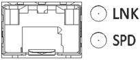
Figure 55 – Location of SFP connector indicators
Figure 56 – Location of RJ-45 connector indicators
The following table lists description of system indicator statuses and meanings.
Table 46 – Status of system indicators
Indicator name | Indicator function | LED State | Device State |
|---|---|---|---|
Power | Device power LED. | Green | Device power is normal operation state. Main power supply, if installed, is operational. The main software is uploaded. |
Red | The main software is not loaded. | ||
Off | Device internal power supply failure. | ||
Status | Current device status LED. | Green | Device is in normal operation state. |
Orange | Device is booting up the software. | ||
Alarm | Alarm LED. | - | - |
HA | HA operation mode LED (not supported in the current version) | - | - |
ESR-30 light indication
Gigabit Ethernet copper interface statuses are represented by two LEDs – green LINK/ACT LED and amber SPEED LED.
Table 47 – Light indication of copper and SFP interfaces status
SPEED indicator is lit | LINK/ACT indicator is lit | Ethernet interface state |
|---|---|---|
Off | Off | The port is disabled or connection is not established. |
Off | Solid on | 10 Mbps or 100 Mbps connection is established. |
Solid on | Solid on | 1000 Mbps connection is established. |
X | Flashes | Data transfer is in progress. |
Figure 57 – Location of SFP connector indicators
Figure 58 – Location of RJ-45 connector indicator
The following table lists description of system indicator statuses and meanings.
Table 48 – Status of system indicators
Indicator name | Indicator function | LED State | Device State |
|---|---|---|---|
Power | Device power LED. | Green | Device power is normal operation state. Main power supply, if installed, is operational. The main software is uploaded. |
Red | The main software is not loaded. | ||
Off | Device internal power supply failure. | ||
Status | Current device status LED. | Green | Device is in normal operation state. |
Flashes green | Device is booting up the software. | ||
Alarm | Alarm LED. | - | - |
HA | HA operation mode LED (not supported in the current version) | - | - |
ESR-15 light indication
Gigabit Ethernet copper interfaces statuses are represented by amber SPEED LED.
Table 49 – Light indication of copper interface status
SPEED indicator is lit | Ethernet interface state |
|---|---|
Off | Port is disabled or connection is not established |
Solid amber on | 1000 Mbps connection is established |
| Solid green on | 10 Mbps or 100 Mbps connection is established |
Flashes | Data transfer is in progress |
The following table lists description of system indicator statuses and meanings.
Table 50 – Status of system indicators
Indicator name | Indicator function | LED State | Device State |
|---|---|---|---|
Power | Device power LED. | Green | Device power is normal operation state. Main power supply, if installed, is operational. The main software is uploaded. |
Red | The main software is not loaded. | ||
Off | Device internal power supply failure. | ||
| USB1, USB2 | Indicators of operation of external USB devices. | Green | USB device is connected. |
Flashes green | Read/write operation execution. | ||
| Off | No devices connected or connectivity issues. |
ESR-12V(F) light indication
Gigabit Ethernet copper interface statuses are represented by two LEDs – green LINK/ACT LED and amber SPEED LED.
Table 51 – Light indication of copper and SFP interface status
SPEED indicator is lit | LINK/ACT indicator is lit | Ethernet interface state |
|---|---|---|
Off | Off | Port is disabled or connection is not established |
Off | Solid on | 10 Mbps or 100 Mbps connection is established |
Solid on | Solid on | 1000 Mbps connection is established |
X | Flashes | Data transfer is in progress |
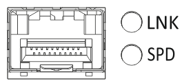
Figure 57 – Location of SFP connector indicators (only for ESR-12VF, ESR-14VF)
Figure 58 – Location of RJ-45 connector indicators
The following table lists description of system indicator statuses and meanings.
Table 52 – Status of system indicators
Indicator name | Indicator function | LED State | Device State |
|---|---|---|---|
Power | Device power LED. | Green | Device power is normal. Main power supply, if installed, is operational. The main software is uploaded. |
Red | The main software is not uploaded. | ||
Off | Device internal power supply failure. |
ESR-10 light indication
Gigabit Ethernet copper interfaces statuses are represented by amber SPEED LED.
Table 53 – Light indication of copper interface status
SPEED indicator is lit | Ethernet interface state |
|---|---|
Off | Port is disabled or connection is not established |
Solid amber on | 1000 Mbps connection is established |
| Solid green on | 10 Mbps or 100 Mbps connection is established |
Flashes | Data transfer is in progress |
Table 54 – Status of system indicators
Indicator name | Indicator function | LED State | Device State |
|---|---|---|---|
Power | Device power LED. | Green | Device power is normal operation state. Main power supply, if installed, is operational. The main software is uploaded. |
Red | The main software is not loaded. | ||
Off | Device internal power supply failure. | ||
| USB1, USB2 | Indicators of operation of external USB devices. | Green | USB device is connected. |
Flashes green | Read/write operation execution. | ||
| Off | No devices connected or connectivity issues. |
Delivery package
ESR-10 standard delivery package includes:
- ESR-10 router;
- 220 VAC/12 VDC, 1.5 A power adapter;
- Conformity certificate;
- Documentation (optional).
ESR-12V standard delivery package includes:
- ESR-12V router;
- Power cable;
- Console cable;
- 19” rack mounting kit;
- Conformity certificate;
- Documentation (optional).
ESR-12VF standard delivery package includes:
- ESR-12VF router;
- Power cable;
- Console cable;
- 19” rack mounting kit;
- Conformity certificate;
- Documentation (optional).
ESR-14VF standard delivery package includes:
- ESR-14VF router;
- Power cable;
- 19” rack mounting kit;
- Conformity certificate;
- Documentation (optional).
ESR-15 standard delivery package includes:
- ESR-15 router;
- 220 VAC/12 VDC, 1.5 A power adapter;
- Conformity certificate;
- Documentation (optional).
ESR-20 standard delivery package includes:
- ESR-20 router;
- Power cable;
- Console cable;
- 19” rack mounting kit;
- Conformity certificate;
- Documentation (optional).
ESR-21 standard delivery package includes:
- ESR-21 router;
- Power cable;
- Console cable;
- 19” rack mounting kit;
- Conformity certificate;
- Documentation (optional).
ESR-30 standard delivery package includes:
- ESR-21 router;
- Power cable;
- Console cable;
- 19” rack mounting kit;
- Conformity certificate;
- Documentation (optional).
ESR-100 standard delivery package includes:
- ESR-100 router;
- Power cable;
- Console cable;
- 19” rack mounting kit;
- Conformity certificate;
- Documentation (optional).
ESR-200 standard delivery package includes:
- ESR-200 router;
- Power cable;
- Console cable;
- 19” rack mounting kit;
- Conformity certificate;
- Documentation (optional).
ESR-1000 standard delivery package includes:
- ESR-1000 router;
- Console cable;
- 19” rack mounting kit;
- Conformity certificate;
- Documentation (optional).
ESR-1200 standard delivery package includes:
- ESR-1200 router;
- Console cable;
- 19” rack mounting kit;
- Conformity certificate;
- Documentation (optional).
ESR-1500 standard delivery package includes:
- ESR-1500 router;
- Console cable;
- 19” rack mounting kit;
- Conformity certificate;
- Documentation (optional).
ESR-1511 standard delivery package includes:
- ESR-1511 router;
- Console cable;
- 19” rack mounting kit;
- Conformity certificate;
- Documentation (optional).
ESR-1700 standard delivery package includes:
- ESR-1700 router;
- Console cable;
- 19” rack mounting kit;
- Conformity certificate;
- Documentation (optional).
ESR-3100 standard delivery package includes:
- ESR-3100 router;
- Console cable;
- 19” rack mounting kit;
- Conformity certificate;
- Documentation (optional).
ESR-3200 standard delivery package includes:
- ESR-3200 router;
- Console cable;
- 19” rack mounting kit;
- Conformity certificate;
- Documentation (optional).
Power module (PM-160-220/12 or PM-100-48/12) may be included in the ESR-1000, ESR-1200 delivery package on the customer's request.
Power module (PM-160-220/12) may be included in the ESR-1500, ESR-1511, ESR-3100, ESR-3200 delivery package on the customer's request.
Power module (PM-350-220/12 or PM-350-48/12) may be included in the ESR-1700 delivery package on the customer's request.
SFP/SFP+ transceivers may be included in the delivery package on the customer's request.