С ЧИПОМ. Redundancy management
VRRP configuration
VRRP ( Virtual Router Redundancy Protocol) is a network protocol designed for increased availability of routers, acting as a default gateway. This is performed by aggregation of a router group into a single virtual router and assigning a shared IP address, that will be used as a default gateway for computers in the network.
Configuration algorithm
Step | Description | Command | Keys |
|---|---|---|---|
1 | Switch to the interface/tunnel/network bridge configuration mode for which it is necessary to configure VRRP | esr(config)# interface <IF-TYPE><IF-NUM> | <IF-TYPE> – interface type; <IF-NUM> – F/S/P – F frame (1), S – slot (0), P – port. |
esr(config)# tunnel <TUN-TYPE><TUN-NUM> | <TUN-TYPE> – tunnel type; <TUN-NUM> – tunnel number. | ||
esr(config)# bridge <BR-NUM> | <BR-NUM> – bridge number. | ||
2 | Configure the required parameters on the interface/tunnel/network bridge including IP address | ||
3 | Enable VRRP process on IP interface. | esr(config-if-gi)# vrrp | |
esr(config-if-gi)# ipv6 vrrp | |||
4 | Set virtual IP address of VRRP router. | esr(config-if-gi)# vrrp ip <ADDR/LEN> | <ADDR/LEN> – virtual IP address, defined as AAA.BBB.CCC.DDD/EE where each part AAA-DDD takes values of [0..255] and EE takes values of [1..32]. You can specify several IP addresses separated by commas. Up to 4 IP addresses can be assigned to the interface. |
esr(config-if-gi)# ipv6 vrrp ip <IPV6-ADDR> | <IPV6-ADDR> – virtual IPv6 address, defined as X:X:X:X::X where each part takes values in hexadecimal format [0..FFFF]. You can specify up to 8 IPv6 addresses separated by commas. | ||
5 | Set the VRRP router identifier. | esr(config-if-gi)# vrrp id <VRID> | <VRID> – VRRP router identifier, takes values in the range of [1..255]. |
esr(config-if-gi)# ipv6 vrrp id <VRID> | |||
6 | Set the VRRP router priority (optionally). | esr(config-if-gi)# vrrp priority <PR> | <PR> – VRRP router priority, takes values in the range of [1..254]. Default value: 100. |
esr(config-if-gi)# ipv6 vrrp priority <PR> | |||
7 | Identify the VRRP router’s inherence to a group. The group provides the ability to synchronize several VRRP processes, so if in one of the processes there is a wizard change, then in another process roles will also be changed (optionally). | esr(config-if-gi)# vrrp group <GRID> | <GRID> – VRRP router group identifier, takes values in the range of [1..32]. |
esr(config-if-gi)# ipv6 vrrp group <GRID> | |||
8 | Set the IP address that will be used as a source IP address for VRRP messages (optionally). | esr(config-if-gi)# vrrp source-ip <IP> | <ADDR> – sender IP address, defined as AAA.BBB.CCC.DDD where each part takes values of [0..255]; |
esr(config-if-gi)# ipv6 vrrp source-ip <IPV6> | <IPV6> – source IPv6 address, defined as X:X:X:X::X where each part takes values in hexadecimal format [0..FFFF]. | ||
9 | Set the interval between sending VRRP messages (optionally). | esr(config-if-gi)# vrrp timers advertise <TIME> | <TIME> – time in seconds, takes values of [1..40]. Default value: 1 second. |
esr(config-if-gi)# ipv6 vrrp timers advertise <TIME> | |||
10 | Set the interval after which GratuituousARP messages are sent when switching the router to the Master status (optionally). | esr(config-if-gi)# vrrp timers garp delay <TIME> | <TIME> – time in seconds, takes values of [1..60]. Default value: 5 seconds. |
11 | Set the amount of GratuituousARP messages that will be sent when switching the router to the Master status (optionally). | esr(config-if-gi)# vrrp timers garp repeat <COUNT> | <COUNT> – amount of messages, takes values of [1..60]. Default value: 5. |
12 | Set the interval after which GratuituousARP messages will be sent periodically while the router is in the Master status (optionally). | esr(config-if-gi)# vrrp timers garp refresh <TIME> | <TIME> – time in seconds, takes values of [1..65535]. Default value: Periodic sending is disabled. |
13 | Set the amount of GratuituousARP messages that will be sent with the garprefresh period while the router is in the Master status (optionally). | esr(config-if-gi)# vrrp timers garp refresh-repeat <COUNT> | <COUNT> – amount of messages, takes values of [1..60]. Default value: 1. |
14 | Specify whether the higher priority Backup router would try to take the Master role from the current lower priority Master router (optionally). | esr(config-if-gi)# vrrp preemption disable | |
esr(config-if-gi)# ipv6 vrrp preemption disable | |||
15 | Set the time interval after which the higher priority Backup route will try to take the Master role from the current lower priority Master router (optionally). | esr(config-if-gi)# vrrp preemption delay <TIME> | <TIME> – timeout, takes value in seconds [1..1000]. Default value: 0 |
esr(config-if-gi)# ipv6 vrrp preemption delay <TIME> | |||
16 | Set the password for neighbour authentication (optionally). | esr(config-if-gi)# vrrp authentication key ascii-text | <CLEAR-TEXT> – password, set by the string of 8 to 16 characters; <ENCRYPTED-TEXT> – encrypted password of 8 to 16 bytes (from 16 to 32 characters) in hexadecimal format (0xYYYY ...) or (YYYY ...). |
17 | Specify authentication algorithm (optionally). | esr(config-if-gi)# vrrp authentication algorithm <ALGORITHM> | <ALGORITHM> – authentication algorithm:
|
18 | Specify VRRP version (optionally). | esr(config-if-gi)# vrrp version <VERSION> | <VERSION> – VRRP version: 2, 3. |
19 | Set the mode when vrrp IP address remains in the UP status regardless of the status of the interface itself. (optionally) | esr(config-if-gi)# vrrp force-up | |
20 | Specify the delay between the assignment of MASTER status to ipv6 vrrp and the start of ND messages distribution (optionally). | esr(config-if-gi)# ipv6 vrrp timers nd delay <TIME> | <TIME> – time in seconds, takes values of [1..60]. Default value: 5 |
21 | Specify the period of ND protocol information update for ipv6 vrrp in MASTER status (optionally). | esr(config-if-gi)# ipv6 vrrp timers nd refresh <TIME> | <TIME> – time in seconds, takes values of [1..65535]. Default value: 5 |
22 | Specify the amount of ND messages sent in the update period for ipv6 vrrp in MASTER status (optionally). | esr(config-if-gi)# ipv6 vrrp timers nd refresh-repeat <NUM> | <NUM> – amount, takes values of [1..60]. Default value: 0 |
23 | Specify the amount of ND packets sendings after setting ipv6 vrrp to the MASTER status (optionally). | esr(config-if-gi)# ipv6 vrrp timers nd repeat <NUM> | <NUM> – amount, takes values of [1..60]. Default value: 1 |
Configuration example 1
Objective:
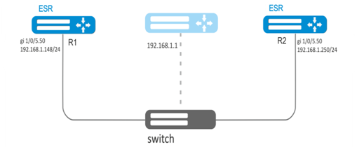
Establish LAN virtual gateway in VLAN 50 using VRRP. IP address 192.168.1.1 is used as a local virtual gateway.
Solution:
First, do the following:
- create a correspond sub interface;
- configure a zone for the sub-interface;
- specify IP address for the sub-interface.
Main configuration step:
Configure R1 router.
Configure VRRP in the created sub-interface. Specify unique VRRP identifier:
R1(config)#interface gi 1/0/5.50
R1(config-subif)# vrrp id 10Specify virtual gateway IP address 192.168.1.1/24:
R1(config-subif)# vrrp ip 192.168.1.1Enable VRRP:
R1(config-subif)# vrrp
R1(config-subif)# exitAfter that it is necessary to make the same settings on R2.
Configuration example 2
Objective:
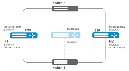
Establish virtual gateways for 192.168.20.0/24 subnet in VLAN 50 and 192.168.1.0/24 in VLAN 60 using VRRP with Master sync feature. To do this, you have to group VRRP processes. IP addresses 192.168.1.1 and 192.168.20.1 are used as virtual gateways.
Solution:
First, do the following:
- create correspond sub interfaces;
- configure a zone for the sub-interfaces;
- specify IP addresses for the sub-interfaces.
Main configuration step:
Configure R1 router.
Configure VRRP for 192.168.1.0/24 subnet in the created sub-interface.
Specify unique VRRP identifier:
R1(config-sub)#interface gi 1/0/5.50
R1(config-subif)# vrrp id 10Specify virtual gateway IP address 192.168.1.1:
R1(config-subif)# vrrp ip 192.168.1.1Specify VRRP group identifier:
R1(config-subif)# vrrp group 5Enable VRRP:
R1(config-subif)# vrrp
R1(config-subif)# exitConfigure VRRP for 192.168.20.0/24 subnet in the created sub-interface.
Specify unique VRRP identifier:
R1(config-sub)#interface gi 1/0/6.60
R1(config-subif)# vrrp id 20Specify virtual gateway IP address 192.168.1.20:
R1(config-subif)# vrrp ip 192.168.20.1Specify VRRP group identifier:
R1(config-subif)# vrrp group 5Enable VRRP:
R1(config-subif)# vrrp
R1(config-subif)# exitConfigure R2 in the same manner.
In addition to tunnel creation, you should enable VRRP protocol (112) in the firewall.
VRRP tracking configuration
VRRP tracking is a mechanism, which allows activating static routes, depending on VRRP state.
Configuration algorithm
Step | Description | Command | Keys |
|---|---|---|---|
1 | Configure VRRP according to the section «VRRP configuration algorithm». |
| |
2 | Add Tracking object to the system and switch to the Tracking object parameters configuration mode. | esr(config)#tracking <ID> | <ID> – Tracking object number, takes values of [1..60]. |
3 | Specify a rule for keeping track of VRRP process status. | esr(config-tracking)# vrrp <VRID> [not] state { master | backup | fault } | <VRID> – trackable VRRP router identifier, takes values in the range of [1..255]. |
4 | Enable Tracking object. | esr(config-tracking)#enable | |
5 | Create a static IP route to the specified subnet indicating the Tracking object. | esr(config)# ip route [ vrf <VRF> ] <SUBNET> { <NEXTHOP> [ resolve ] | | <VRF> – VRF name, set by the string of up to 31 characters. <SUBNET> – destination address, can be specified in the following formats: AAA.BBB.CCC.DDD – host IP address, where each part takes values of [0..255]. AAA.BBB.CCC.DDD/NN – network IP address with prefix mask, where AAA-DDD take values of [0..255] and NN takes values of [1..32]. <NEXTHOP> – gateway IP address, defined as AAA.BBB.CCC.DDD where each part takes values of [0..255];
<IF> – an IP interface name specified in the form described in Section Types and naming order of router interfaces; <TUN> – the name of the tunnel is specified as described in section Types and naming order of router tunnels; <RULE> – wan rule number, set in the range of [1..50];
<METRIC> – route metric, takes values of [0..255]; <TRACK-ID> – Tracking object identifier. If the router is bound to the Tracking object, it will appear in the system only after meeting all requirements specified in the object. |
6 | Configure IP address, the availability of which is checked by sending pings. It is necessary to allow ICMP on the Firewall. | esr(config-bridge)# vrrp track-ip <AAA.BBB.CCC.DDD> | AAA.BBB.CCC.DDD – host IP address, where each part takes values of [0..255]. |
7 | The interval at which pings are sent. | esr(config-bridge)# vrrp track-ip <seconds> | <seconds> – time interval in seconds [3..60]. Default |
8 | The number of pings that are sent when monitoring a remote | esr(config-bridge)# vrrp track-ip packets <packets> | <packets> – number of packets to be sent [1..5]. Default value: 5 |
Configuration example
Objective:
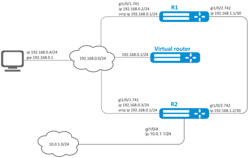
Virtual gateway 192.168.0.1/24 is organized for 192.168.0.0/24 subnet, using VRRP protocol and routers R1 and R2. There is a link with a singular subnet 192.168.1.0/30 between R1 and R2 routers. Subnet 10.0.1.0/24 is terminated only on R2 router. PC has IP address - 192.168.0.4/24 and default gateway 192.168.1.1.
When router R1 is in vrrp backup state, traffic from PC will be transmitted without any additional settings. When router R1 is in vrrp master state, additional route is necessary for subnet 10.0.1.0/24 through interface 192.168.1.2.
Initial configurations of the routers:
R1 router
hostname R1
interface gigabitethernet 1/0/1
  switchport forbidden default-vlan
exit
interface gigabitethernet 1/0/1.741
  ip firewall disable
  ip address 192.168.0.2/24
  vrrp id 10
  vrrp ip 192.168.0.1/24
  vrrp
exit
interface gigabitethernet 1/0/2
  switchport forbidden default-vlan
exit
interface gigabitethernet 1/0/2.742
  ip firewall disable
  ip address 192.168.1.1/30
exitR2 router
hostname R2
interface gigabitethernet 1/0/1
  switchport forbidden default-vlan
exit
interface gigabitethernet 1/0/1.741
  ip firewall disable
  ip address 192.168.0.3/24
  vrrp id 10
  vrrp ip 192.168.0.1/24
  vrrp
exit
interface gigabitethernet 1/0/2
  switchport forbidden default-vlan
exit
interface gigabitethernet 1/0/2.742
  ip firewall disable
  ip address 192.168.1.2/30
exit
interface gigabitethernet 1/0/4
  ip firewall disable
  ip address 10.0.1.1/24
exitSolution:
There is no need in any changes in router R2, since subnet 10.0.1.0/24 is terminated on it and as soon as router R2 is vrrp master, packets will be transmitted to corresponding interface. As soon as R1 becomes vrrp master, route for packets must be created with destination IP address from network 10.0.1.0/24.
Create tracking-object with corresponding condition:
R1(config)# tracking 1
R1(config-tracking)# vrrp 10 state master
R1(config-tracking)# enable
R1(config-tracking)# exitCreate static route to subnet 10.0.1.0/24 through 192.168.1.2, which will work in case of satisfying of tracking 1 condition:
R1(config)# ip route 10.0.1.0/24 192.168.1.2 track 1