| Scroll pdf ignore |
|---|
Base station |
| A Shared Block | |||||
|---|---|---|---|---|---|
| |||||
|
| Оглавление | ||||||
|---|---|---|---|---|---|---|
|
Introduction
Annotation
Modern trends of telecommunication development make operators find the most optimal technologies in order to satisfy rapidly growing needs of subscribers, at the same time maintaining consistency of business processes and flexibility in development, as well as reducing the costs of various services provision. Wireless technologies are gaining momentum and have evolved very quickly from unstable low-speed small radius communication networks to broadband networks comparable in speed to wired networks with high criteria for the quality of provided services.
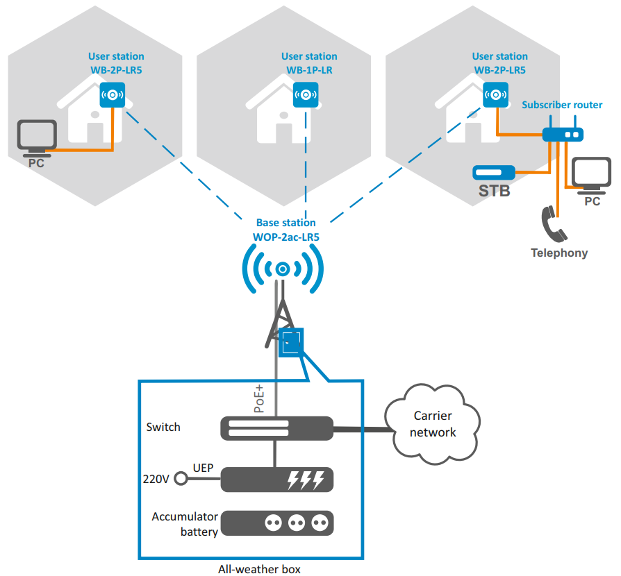
WOP-2ac-LR5 is indended for organization of broadband networks in private housing. The device provides clients with wireless Internet access in the range of up to 3 km and Triple Play services. The device is a good choice for wireless network construction in any climatic conditions: in a wide operating temperature range and in high humidity. The device allows connecting different sectoral antennas.
This manual specifies intended purpose, main technical parameters, design, installation procedure and instructions for configuring, monitoring and updating of WOP-2ac-LR5 base station.
Explanation of the symbols used
Notes and warnings
| Подсказка |
|---|
Notes contain important information, tips or recommendations on device operation and setup. |
| Предупреждение |
|---|
Warnings inform users about hazardous conditions, which may cause injuries or device damage and may lead to the device malfunctioning or data loss. |
Device description
Purpose
The base station WOP-2ac-LR5 (hereinafter 'the device') has been designed to provide subscribers with wireless Internet access in the range of up to 3 km and to organize wireless bridges (WDS).
The device provides access to modern interactive services: Internet, IPTV, VoIP.
The base station WOP-2ac-LR5 – an up-to-date flexible solution that provides extending coverage zone due to the power of its transmitter (up to 28 dBm) and the use of sectoral antennas. It is possible to deploy wireless IT infrastructure fast and easily by virtue of high-performance hardware, scalability and intuitive interface.
The PoE+ technology makes it possible to install the equipment anywhere, regardless of the power supply location, reduces total cost by discarding power cables and makes installation easier and faster.
Device specification
Interfaces:
- 1 Combo port 10/100/1000BASE-T (Ethernet)/100/1000Base-X (SFP);
- 2 SMA (female) connectors for external antennas. The choice of a model depends on the intended use of the access point: for wireless bridges, it is preferable to choose narrow-band antennas, and in the base station mode, sectoral antennas with a wider directional pattern are should be chosen;
- Wi-Fi 5-6 GHz IEEE 802.11a/n/ac.
The power is supplied via a PoE injector (IEEE 802.3at-2009).
Functions:
WLAN capabilities:
- support for IEEE 802.11a/n/ac;
- data aggregation, including A-MPDU (Tx /Rx) and A-MSDU (Rx);
- WMM-based priorities and packet planning;
- support for hidden SSID;
- 4 virtual access points;
- MAC ACL;
- external access points detection;
- APSD;
- spectrum analyzer;
- support for wireless bridges (WDS);
- Polling;
- support for fixed center frequency;
- intersectoral synchronization (PTP) 1 .
Network functions:
- autonegotiation of speed, duplex mode and switching between MDI and MDI-X modes;
- support for VLAN (Access, Trunk, General);
- DHCP client;
- VLAN mapping;
- support for NTP;
- support for Syslog;
- DHCP snooping;
- IGMP snooping (with possibility to limit the number of groups);
- BPDU filtering.
| Якорь | ||||
|---|---|---|---|---|
|
| Scroll Pagebreak |
|---|
QoS functions:
- bandwidth limiting for each SSID;
- client data rate limiting for each SSID;
- changing WMM parameters for each radio interface;
- support for CoS, DSCP and VLAN ID prioritization.
Security:
- centralized authorization via RADIUS server (WPA Enterprise);
- WPA/WPA2 data encryption;
- 64/128/152-bit WEP data encryption;
Fig. 1 shows an operation diagram for WOP-2ac-LR5.
| Якорь | ||||
|---|---|---|---|---|
|
Technical Features
Table 1 shows main specifications of the device.
Table 1 – Main specifications
Ethernet interface parameters | |
|---|---|
Number of ports | 1 |
Electrical connector | RJ-45/SFP |
Data rate, Mbps | 10/100/1000, auto-negotiation |
Standards | BASE-T/BASE-X |
Port features | Combo port |
Wireless interface parameters | |
Standards | 802.11a/n/ac |
Frequency range, MHz | 5170– 6160 MHz |
Modulation | BPSK, QPSK, 16QAM, 64QAM, 256QAM |
Data transfer rate1, Mbps | 802.11a: up to 54 Mbps |
Maximum transmitter output power2 | 5-6 GHz: 24 dBm (for WOP-2ac-LR5) 28 dBm (for WOP-2ac-LR5 rev.B, WOP-2ac-LR5 SYNC) |
Receiver sensitivity | 5-6 GHz: up to -94 dBm |
Security | 64/128/152- bit WEP encryption, WPA/WPA2, |
Control | |
Remote control | Web interface, CLI, Telnet, SSH, SNMP (monitoring), NETCONF |
Access restriction | Local authentication and authentication via RADIUS server |
General parameters | |
Processor | Realtek RTL8197FS 1 GHz |
RAM | 128 MB |
Flash | 32 MB |
Power supply | PoE+ (IEEE 802.3at-2009) |
Power consumption | no more than 6.5 W (for WOP-2ac-LR5) no more than 16 W (for WOP-2ac-LR5 rev.B, WOP-2ac-LR5 SYNC) |
Range of operation temperatures | from -45 to +65°C |
Operating humidity | up to 95% |
Ingress Protection Marking | IP54 |
Dimensions | 80x232.5x47 mm |
Weight | 0.33 kg (for WOP-2ac-LR5) 0.39 kg (for WOP-2ac-LR5 rev.B, WOP-2ac-LR5 SYNC) |
1 The maximum wireless data rate is defined according to IEEE 802.11n/ac standards. The real bandwidth will be different. Conditions under which a network operates, environmental factors (including a volume of network traffic), network service data, building materials and constructions might decrease the real bandwidth. Environmental factors might also influence a network coverage range.
2 The number of channels and the value of the maximum output power will vary according to the rules of radio frequency regulation in your country. Scroll Pagebreak
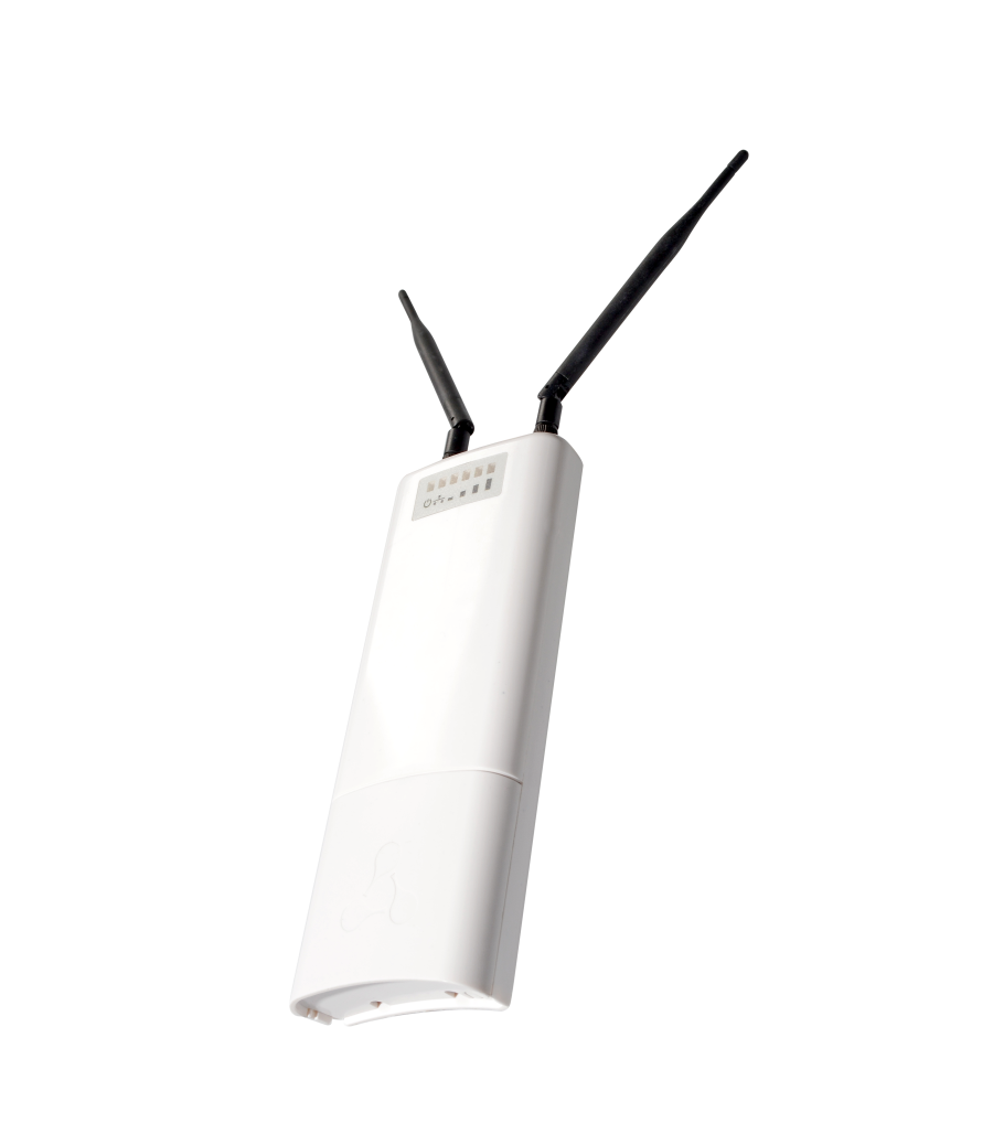
Design
WOP-2ac-LR5 housed in a plastic case, industrial version. The size of the device: 80x232.5x47 mm. The appearance of WOP-2ac-LR5 is shown in the Fig. 2.
| Якорь | ||||
|---|---|---|---|---|
|
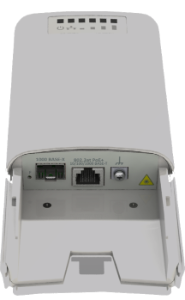
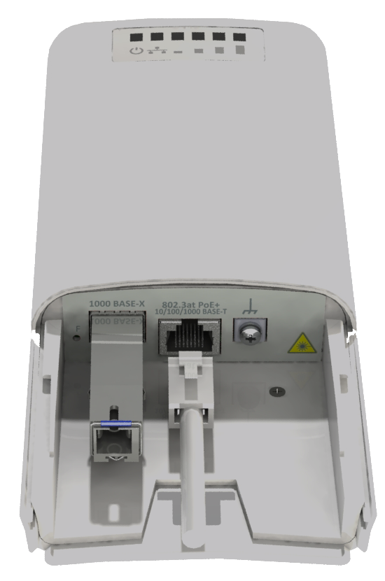
A combo port 10/100/1000Base-T (Ethernet)/100/1000Base-X (SFP) for local network connection and power supply via PoE, a grounding terminal (for WOP-2ac-LR5 H/W version 1v5 and higher; for WOP-2ac-LR5 rev.B, WOP-2ac-LR5 SYNC) and a factory reset button (F) are located under the cover at the bottom of the device, Fig. 3.
| Якорь | ||||
|---|---|---|---|---|
|
| Scroll Pagebreak |
|---|
Light Indication
The appearance of WOP-2ac-LR5 indication panel is shown in the Fig. 4 .
| Якорь | ||||
|---|---|---|---|---|
|
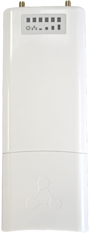
Figure 4 – WOP-2ac-LR5 indication panel appearance
The current state of the device is shown with the help of light indicators located on the front panel of WOP-2ac-LR5. The list of indicators and their description are given in the following table.
Table 2 – Description of indicators
Indicator | Indicator status | Description | |
| Power – power and operation status indicator | solid green | power supply is connected, normal operation |
solid orange | IP address has not been received via DHCP | ||
solid red | the device is loading | ||
| LAN – Ethernet interface port indicator | solid green (10, 100 Mbps)/ | the channel between Ethernet interface of WOP-2ac-LR5 and a connected device is active |
flashes | packet data transmission between Ethernet interface of WOP-2ac-LR5 and a connected device | ||
| WLAN - received signal strength indicator (RSSI) | solid red | the signal level is more than -94 dBm |
| solid orange | the signal level is more than -80 dBm | |
| solid green | the signal level is more than -70 dBm | |
| solid green | the signal level is more than -60 dBm | |
none of the indicators is on | no signal |


Reset to factory settings
You can reset the device configuration using the 'F' button on the device. When the device is loaded, press and hold the «F» button located on the bottom panel (approximately 10–15 seconds) until the «Power» indicator is flashing orange;
Device will be rebooted automatically. DHCP client will be launched by default. If the address is not received via DHCP, the device will have IP address — 192.168.1.10, subnet mask — 255.255.255.0; Username/Password to access via web interface: admin/password.
Delivery package
The basic supply package of WOP-2ac-LR5 includes:
- Base station WOP-2ac-LR5;
- Mounting kit;
- Patch cord RJ-45, 5e category, 1.5 m;
- User manual on a CD (optional);
- Conformity certificate;
- Informational leaflet;
- Technical passport.
Installation order
This section defines safety rules, installation recommendations, setup procedure and the device starting procedure.
Safety Rules
| Якорь | ||||
|---|---|---|---|---|
|
- Do not open the device case. There are no elements intended for user services inside.
- Do not install the device during a thunderstorm. There is a risk of lightning strike.
- Follow voltage, current and frequency requirements specified in the user manual.
- Measuring devices and a computer must be grounded before being connected to the device. The electric potential difference between devices' housings should not exceed 1 V.
- Make sure that all the cables are intact and that they are reliably attached to the connectors.
- The specified standards and requirements for working at height must be met during the device installation on the high-rise constructions.
- The device exploitation should be performed by specially trained engineering and technical personnel.
- Connect only operational service equipment to the device.
Installation recommendations
| Якорь | ||||
|---|---|---|---|---|
|
- Recommended location for device installation: communications mast/pole.
- Before installing and enabling the device, check it for visible mechanical defects. In case of mechanical damage, you should stop the device installation, draw up a corresponding report and contact the supplier.
- Install the device on communications mast or pole in the way that the Ethernet port is pointed down.
- During the device installation, take into account the following rules to provide Wi-Fi coverage area with the best characteristics:
- Install the device in such a way that all subscriber stations that should be connected to this BS get into the antenna range;
- Do not install the device near (about 2 m) electrical and radio devices;
- It is not recommended to use radio phones and other devices, working on frequency of 5-6 GHz, within a range of wireless Wi-Fi network;
- Obstacles such as glass/metal constructions, brick/concrete walls, water cans and mirrors can significantly reduce Wi-Fi network range.
- If several access points are placed on the same mast, it is recommended to spread them vertically by at least 2 meters.
Frequency bands and channels in the range of 5 GHz and 6 GHz for Wi-Fi
Data transmission in the 5-6 GHz band is used for IEEE 802.11a/n/ac standards. WOP-2ac-LR5 supports frequency channels in the range of 5-6 GHz with the bandwidth of 5, 10, 20, 40 and 80 MHz.
To calculate the Wi-Fi channel central frequency, MHz, use the equation:
f=5000+(5*N), where N – Wi-Fi channel number.
| Scroll Pagebreak |
|---|
Recommendations for lightning protection
| Якорь | ||||
|---|---|---|---|---|
|
- The grounding shall be made with insulated stranded wire. The grounding device and the cross-section of the grounding wire must comply with the requirements of the Electrical Code of Practice.
- The first outdoor lightning protection should be installed as close as possible to the base station, connecting them with a short outdoor FTP cable with shielded connectors.
- The second outdoor lightning protection should be installed as close as possible to the PoE switch (PoE injector), connecting them with a short outdoor FTP cable with shielded connectors.
- The lightning protectors are connected to each other by an outdoor FTP cable up to 100 m long.
- The sector antenna must be grounded through the antenna mount mast.
- It is necessary to ground the base station (for more information, see Mounting the device).
- The PoE switch (PoE injector) must be connected to a 220V electrical outlet with ground or grounded through the housing.
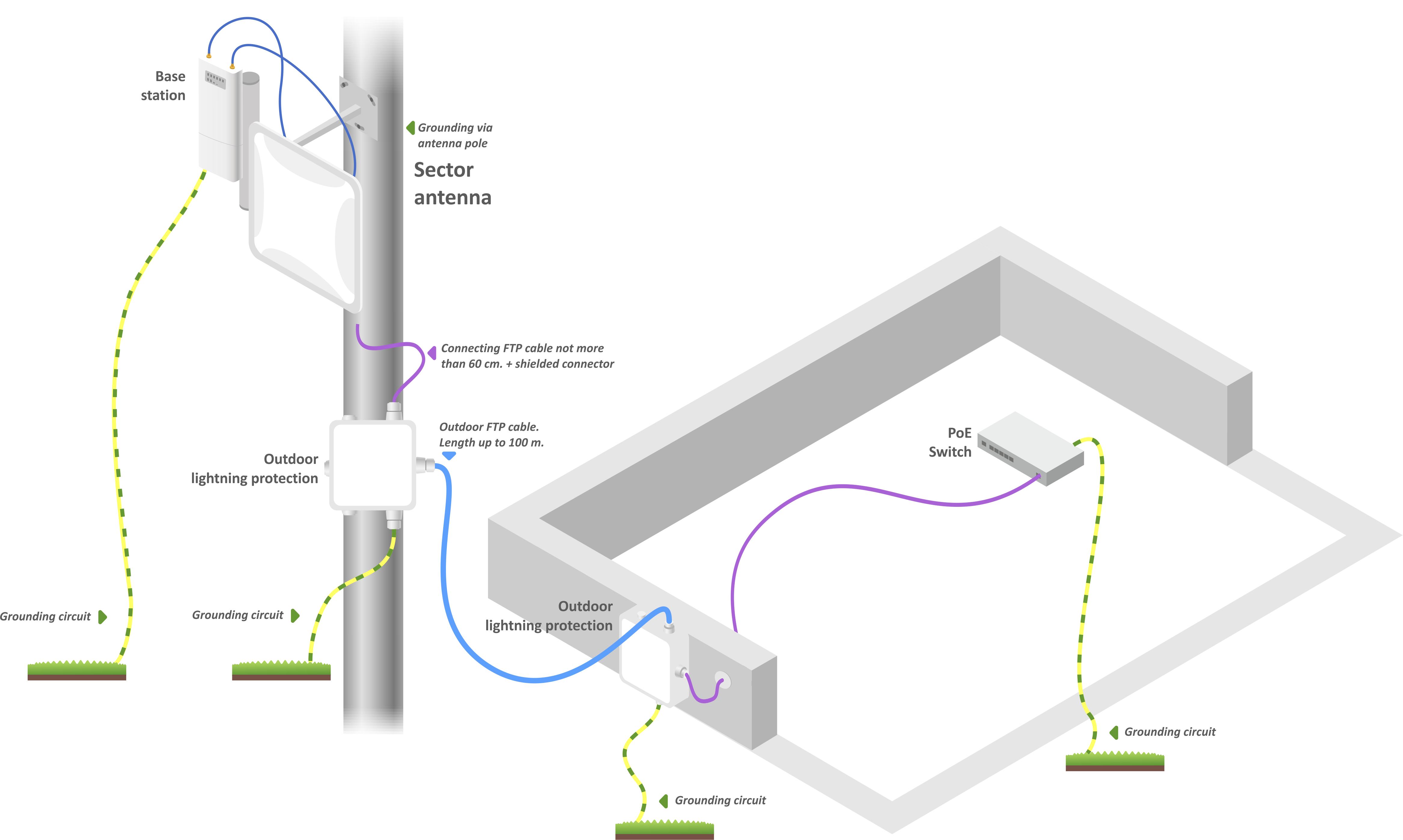
Wiring diagram of the base station to provide lightning protection
| Scroll Pagebreak |
|---|
WOP-2ac-LR5 mounting
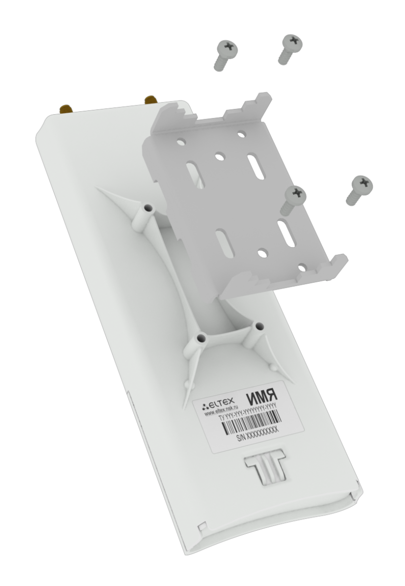
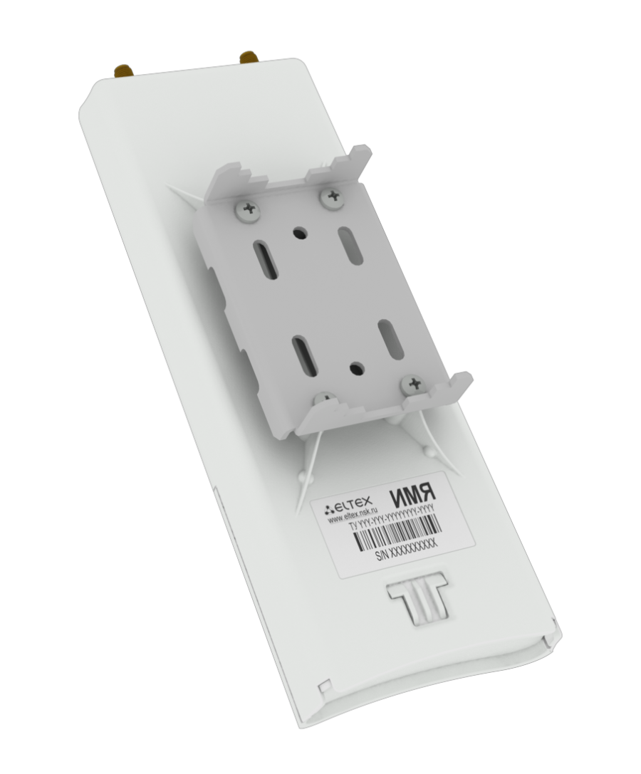
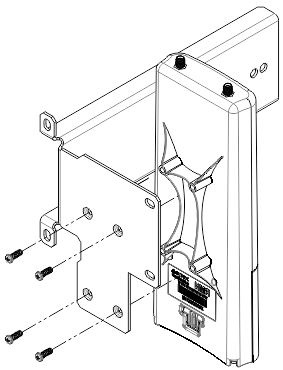
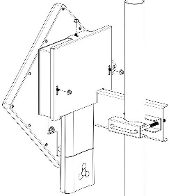
1. Attach the bracket to the device with the screws provided, as shown in the figure below.
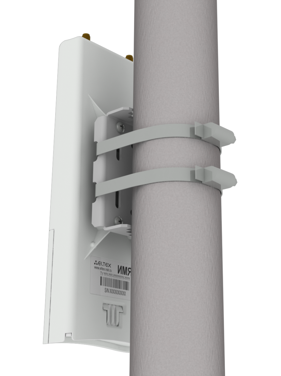
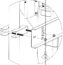
2. Install the device on communications mast/pole with Ethernet port down as it is shown in the figure below. Attach the device using clamps supplied in the device package. Follow the safety rules and recommendations given in Safety rules and Installation recommendations.
3. Remove the cover that closes the Ethernet port on the bottom panel of the device. Ground the device using a grounding connector (for H/W version: 1v5 and higher), then connect the Ethernet cable to the PoE port. When building a network over fiber, install the transceiver and make the connection.
4. Close the bottom cover.
5. Connect the antenna to the device using the cable assemblies.
6. Adjust the position of the antenna so that subscriber devices fall into the coverage area of the installed antenna.
7. Connect the Ethernet cable coming from WOP-2ac-LR5 to the PoE port or the injector or switch (IEEE 802.3at-2009).
8. If you use a PoE injector, connect it to 220 V power supply network using the cable.
9. Adjust the antenna more precisely using light indicators on the device.
| Предупреждение |
|---|
To avoid damage to the device, it is recommended to use lightning protection! |
Antenna connector sealing procedure
| Предупреждение |
|---|
Sealing should be performed on both sides of the cable. |
1. Before connecting the cable to the connector, inspect the cable braid for damage and check for an O-ring in the nut of the connector, the location is shown in Figure 5 (a, b).Scroll Pagebreak
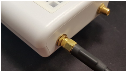 Figure 5a
 Figure 5b
2. Connect the cable to the connector of the device (antenna) and tighten the nut, as shown in Figure 6 (a, b).
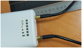 Figure 6a
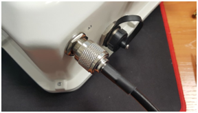 Figure 6b
3. Cut the rubber sealing tape to the appropriate length: 0.15 m of waterproofing tape is required to seal one SMA connector (Figure 26a), 0.3 m of waterproofing tape is required for an N-type connector (Figure 6b), as shown in Figure 7 (a,b).
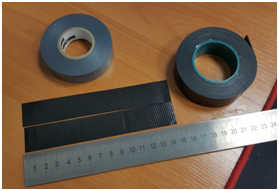
Figure 7a
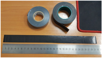 Figure 7b
4. Remove the protective layer from the rubber band as shown in Figure 8.
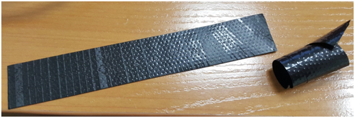 Figure 8
5. Start wrapping from the cable side, with a 10-15 mm step away from the crimped part. Fix the end of the tape on the cable braid at an angle of 15...25 degrees to the cable axis, and, stretching the tape slightly, start wrapping the cable and the connector, advancing towards the device body. Lay the coils overlapping each other, no folds are allowed on the coils. The cable wrapping is shown in Figure 9 (a, b).
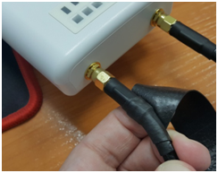 Figure 9a
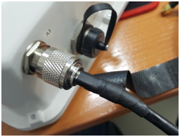 Figure 9b
6. Having reached the housing of the device (antenna) by the edge of the tape, it is required to make a turn around the connector, pressing as much as possible the edge of the tape to the housing, then continue winding the tape at a different angle, moving away from the housing. When winding, do not forget to stretch the tape and press it tightly to the previously wound coils. At the tip of the ribbon, reduce the stretch and press it tightly against the coils on the cable braid, as shown in Figure 10 (a, b).
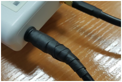 Figure 10a
 Figure 10b
7. Cut PVC tape (duct tape) to the appropriate length: 0.28 m of duct tape is required to seal one SMA connector, 0.6 m of duct tape is required for an N-type connector. Tape is required to protect the rubber band from UV rays. The duct tape is shown in Figure 11.

Figure 11
8. Start wrapping from the cable braid, having preliminarily stepped back from the first coil of the rubber tape by 5-10 mm. Fix the end of the tape on the cable at an angle of 15...25 degrees to the cable axis, and, slightly stretching the tape, start wrapping the cable and the connector, advancing towards the device body. Lay the coils overlapping each other, no folds are allowed on the coils. The winding of the cable is shown in Figure 12.
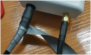
Figure 12
9. Having reached the housing by the edge of the tape, it is required to make a turn around the connector, pressing the edge of the tape to the housing as much as possible, then continue winding the tape at a different angle, moving away from the housing. When winding the tape tightly, do not allow any folds. On the last turns of the tape, reduce the stretch to zero and lay the last turn without stretching, as shown in Figure 13 (a, b).
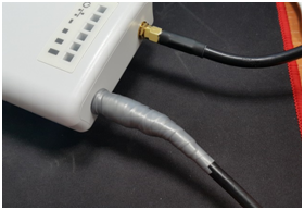 Figure 13a
 Figure 13b
10. Check the sealed connector for visible areas of rubber tape.
WOP-2ac-LR5 RFE mounting
Composition of the kit
- WOP-2ac-LR5 basic device kit;
- RFE antenna assembly;
- Bracket;
- Mounting kit;
- Coaxial cables, 2 pcs.
Kit mounting process
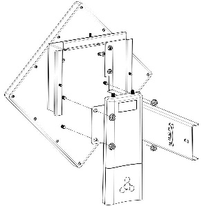
1. Attach the bracket to the unit using the screws provided, as shown in the figure below.
2. Secure the mounting bracket to the antenna with the nuts.
Scroll Pagebreak
3. Connect the coaxial cables to the device and the antenna.
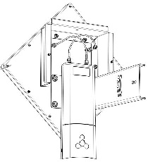
4. Install the resulting assembly on the pole as shown in the figure below. It is necessary that the set is held on the pole, but at the same time is not screwed completely: this is necessary for further alignment of the antenna.
5. Remove the bottom cover which close Ethernet port. Ground the device through a grounding connector, then connect the Ethernet cable to the PoE port. When building a network over fiber, install the transceiver and make the connection.
6. Close the bottom cover.
7. Align the antenna position so that the subscriber devices fall within the coverage area of the installed antenna.
8. Connect the Ethernet cable outgoing form WOP-2ac-LR2 to the injector PoE port or the switch port (IEEE 802.3at-2009).
9. If you using PoE injector connect it to 220 V power supply network using the cable.
10. Align the antenna more accurately using the LEDs on the device.
11. Completely secure the kit to the pole by tightening the nuts.
12. When you have finished setting up the unit, close the connection point with the cover and secure it with the three nuts.
| Предупреждение |
|---|
To avoid damage to the device, it is recommended to use lightning protection! |
Managing the device through WEB interface
Getting started
To start, you need to connect the device through a browser:
1. Open a web browser (web-page explorer), for example, Firefox, Opera, Chrome.
2. Enter IP-address of the device to the browser address bar.
| Подсказка |
|---|
IP address by default: 192.168.1.10, subnet mask: 255.255.255.0. The device is capable to obtain an IP address via DHCP. Factory settings: login: admin, password: password. |
If connection is successful, request form with user name and password will be displayed in a browser window.
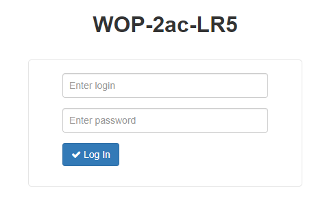
3. Enter Login and Password into corresponding fields.
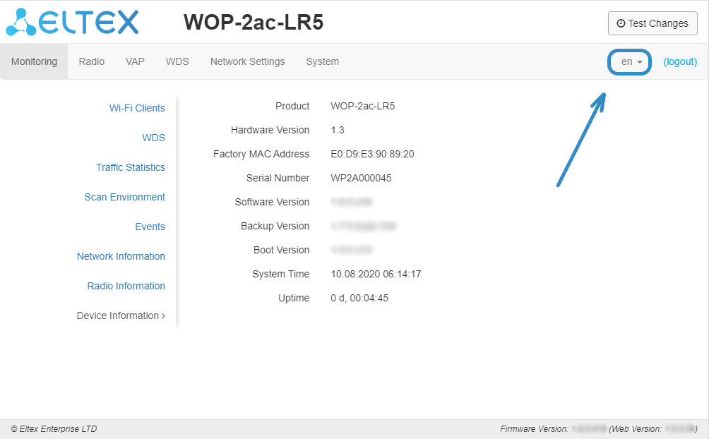
4. Click the ‘Log in’ button. Device Web configurator home page will be opened in the browser window.
5. If necessary, you can switch the display language. Russin and English languages are available for WOP-2ac-LR5.
Applying configuration and discarding changes
- Applying configuration
| Подсказка |
|---|
Click the |
Visual indication of the setting application process' current state is implemented in the web interface, table 3.
Table 3 – Visual indication of the current status of the setting application process
Image | State description |
| After pressing 'Apply', the process of writing settings to device memory is launched. This is indicated by the |
| Successful settings saving and application are indicated by the |
2. Discarding changes
| Подсказка |
|---|
You can discard changes only before pressing 'Apply' button. If you press 'Apply' button, all the changed parameters will be applied and saved to device memory. You will not be able to return to previous configuration after pressing 'Apply'. |
The button for discarding changes appears as follows:  .
.
| Scroll Pagebreak |
|---|
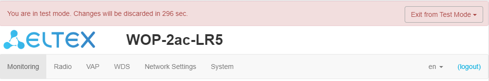
Test changes mode
The device has a test mode for a test configuration application.
To activate it, press the 'Test changes' button on the top panel of the web interface.

Test mode operating time is 300 seconds (5 minutes). During this time you can navigate through the web configurator tabs and make any changes by applying them on each page using the 'Apply' button.
After checking the required configuration, press the 'Exit from Test Mode' button and select the desired action:
- 'Save and exit' – pressing this button will exit the test mode and save to the non-volatile memory all configuration changes that were made and applied in this mode. It will be impossible to undo changes made in the test mode.
- 'Cancel and exit' – pressing will exit the test mode and cancel all changes made in this mode. The configuration in effect on the device before the test mode is activated will be restored.
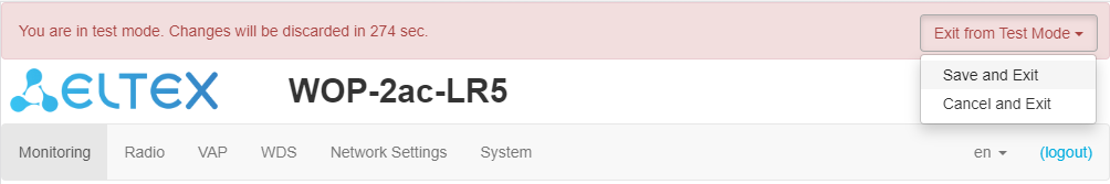
If the administrator does not exit the test mode within 300 seconds, this will happen automatically along with a rollback of all changes that have been made in this mode. After the specified time, the configuration will be restored even if access to the device is lost as a result of the changes made.Scroll Pagebreak
Main Elements of the web Interface
Navigation elements of the web interface are shown in the figure below.
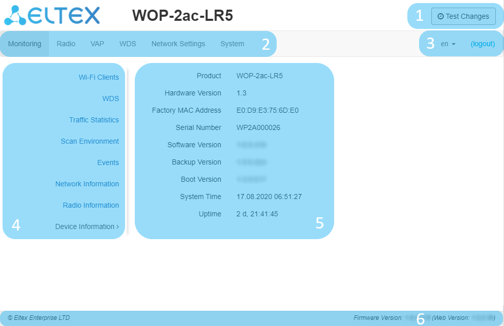
User interface window is divided into five general areas:
- 'Test mode' button – start the configuration testing mode.
- Menu tabs categorize the submenu tabs: Monitoring, Radio, VAP, WDS, Network Settings, System.
- Interface language selection and Logout button designed to to end a session in the web interface under a given user.
- Submenu tabs allows controlling the settings field.
- Device configuration field displays data and configuration.
- Information field displays current firmware version.
| Scroll Pagebreak |
|---|
The 'Monitoring' menu
The 'Monitoring' menu displays the current system status.
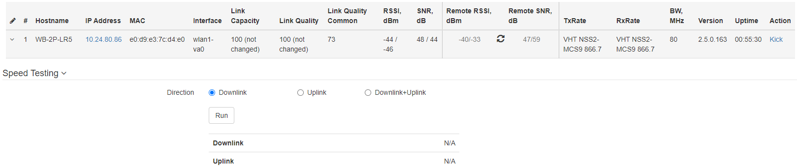
The 'Wi-Fi Clients' submenu
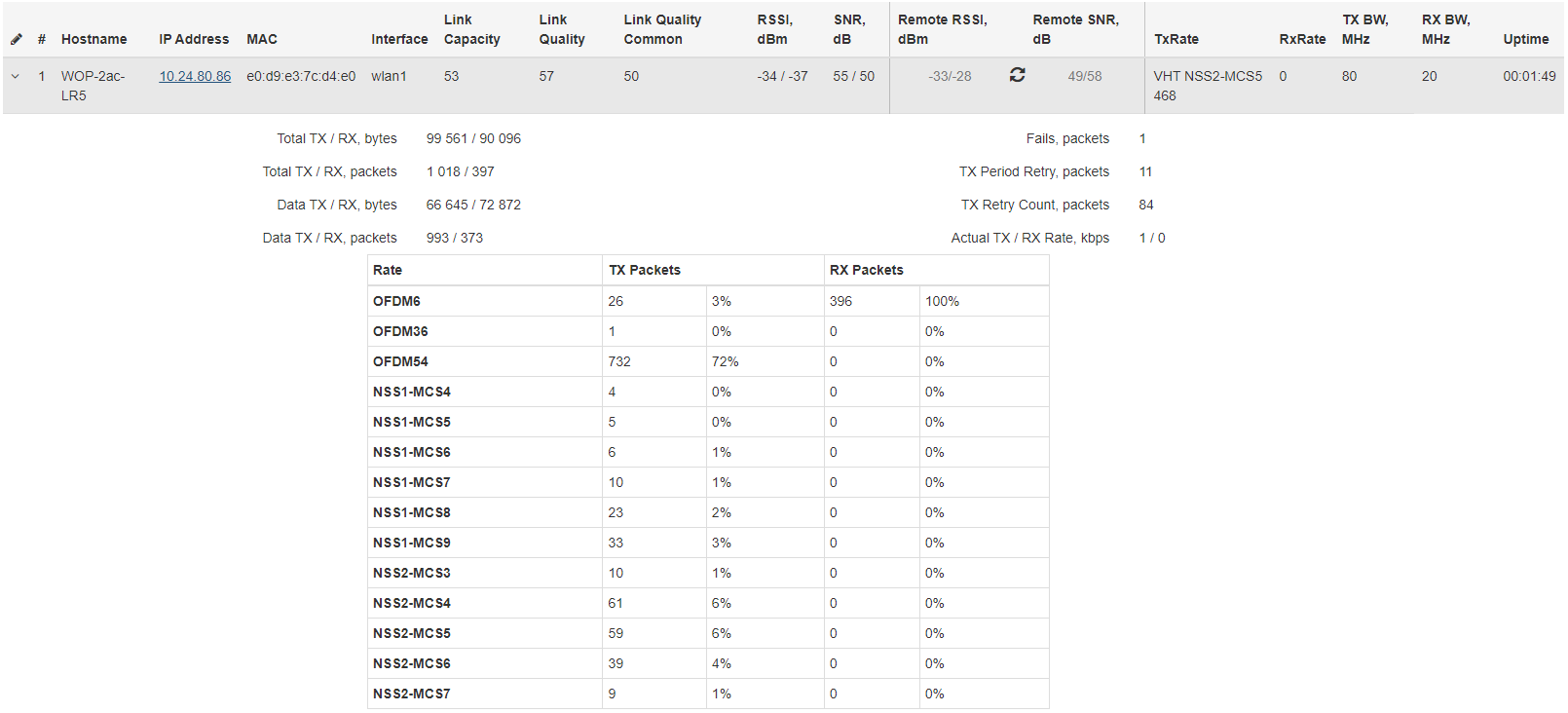
The 'Wi-Fi clients' submenu displays information about the status of connected Wi-Fi clients, traffic statistics and link speed testing.
| Подсказка |
|---|
For ease of monitoring, there is an option to select the parameters to display. To do this, click on the |
- # – number of the connected device in the list;
- Hostname – network name of the device;
- IP Address – IP address of the connected device;
- MAC – MAC address of the connected device;
- Interface – WOP-2ac-LR5 interface for interaction with the connected device;
- Link Capacity – parameter that reflects the efficiency of modulation on the transmission used by an access point. It is calculated based on the number of packets transmitted to the client on each modulation, and the reduction factors. The maximum value is 100% (means that all packets are transmitted to the client at maximum modulation for the maximum nss type supported by the client). The minimum value is 2% (in the case when the packets are transmitted on the modulation nss1mcs0 for a client with MIMO 3x3 support). The parameter value is calculated for the last 10 s;
- Link Quality – parameter that displays the status of the link to the client, calculated based on the number of retransmit packets sent to the client. The maximum value is 100% (all transmitted packets were sent on the first attempt), the minimum value is 0% (no packets were successfully sent to the client). The parameter value is calculated for the last 10 s;
- Link Quality Common – parameter that displays the status of the link to the client, calculated based on the number of retransmitted packets sent to the client. The maximum value is 100% (all transmitted packets were sent on the first attempt), the minimum value is 0% (no packets were successfully sent to the client). The parameter value is calculated for all the time the client is connected;
- RSSI – received signal level, dBm;
- SNR – signal/noise ratio, dB;
- Remote RSSI – output of the received signal level from the subscriber station, dBm;
- Remote SNR – output of the signal/noise ratio level from the subscriber station, dB;
- TxRate – channel data rate of transmission, Mbps;
- RxRate – channel data rate of receiving, Mbps;
- BW – radio channel bandwidth, MHz;
- Version – firmware version of the WB-2P-LR5 subscriber station. Subscriber station should have the firmware version 2.4.1 and higher;
- Uptime – Wi-Fi client connection time;
- Action – when clicking on the 'Kick' button, the Wi-Fi connection with the subscriber station will be broken. Subscriber station will reconnect.
| Подсказка |
|---|
The Remote RSSI and Remote SNR values are not updated in real time. To request the current values, click |
The 'Speed Testing' subsection is designed to test the speed of the link in the direction from the base station to the subscriber station and back:
- Downlink – speed test will be performed in the direction from the base station to the subscriber station;
- Uplink – speed test will be performed in the direction from the subscriber station to the base station;
- Downlink+Uplink – speed test will be performed alternately in each direction.
The test is performed with TCP traffic and lasts 10 seconds for one direction. The test can only be run to one subscriber station at a time. Subscriber station must have firmware version 2.4.4 or higher.
To run the test, select the direction and click the 'Run' button. After completing the test, the result will be displayed in the appropriate field.
By default, VLAN 7 and subnet 192.0.4.0/24 are used for the test. If the network already uses this subnet and VLAN, you should change the settings for the test so that they do not overlap with existing networks. This can be done through the CLI. The process is described in more detail in section 'WOP-2ac-LR5. User manual#Speed Speed Testing'.
The 'Advanced Traffic Statistics' subsection contains information about the amount of transmitted and received traffic, errors and retries, the current speed and packet statistics by modulation.
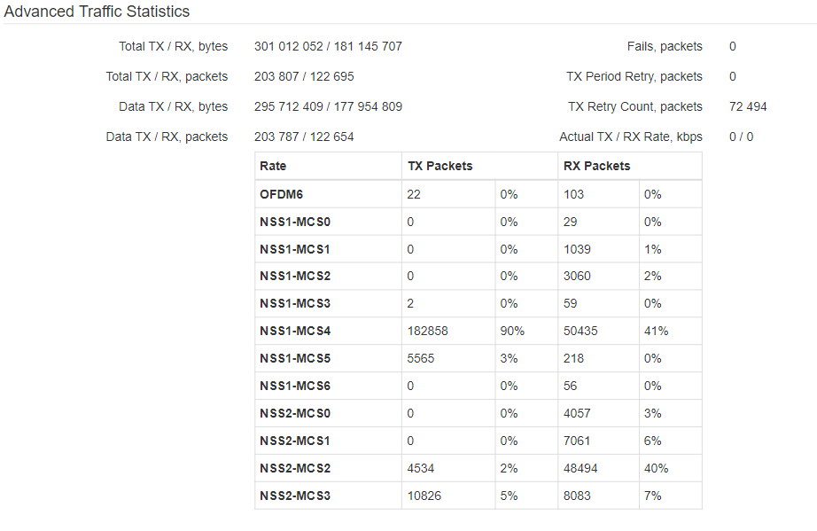
- Total TX / RX, bytes – the number of bytes sent/received on the connected device;
- Total TX / RX, packets – the number of packets sent/received on the connected device;
- Data TX / RX, bytes – the number of data bytes sent/received on the connected device;
- Data TX / RX, packets – the number of data packets sent/received on the connected device;
- Fails, packets – the number of packets sent with errors to the connected device;
- TX Period Retry, packets – the number of retransmissions to the connected device in the last 10 s;
- TX Retry Count, packets – the number of retransmissions to the connected device during all the time of connection;
- Actual TX / RX Rate, kbps – the current traffic transmission rate.
Scroll Pagebreak
The 'WDS' submenu
The 'WDS' submenu displays information about the status of WOP-2ac-LR5 connected via WDS.
| Подсказка |
|---|
For ease of monitoring, there is an option to select the parameters to display. To do this, click on the |
- # – number of the connected device in the list;
- Hostname – network name of the device;
- IP address – IP address of the connected device;
- MAC address – MAC address of the connected device;
- Interface – WOP-2ac-LR5 interface for interaction with the connected device;
- Link Capacity – parameter that reflects the efficiency of modulation on the transmission used by an access point. It is calculated based on the number of packets transmitted to the client on each modulation, and the reduction factors. The maximum value is 100% (means that all packets are transmitted to the client at maximum modulation for the maximum nss type supported by the client). The minimum value is 2% (in the case when the packets are transmitted on the modulation nss1mcs0 for a client with MIMO 3x3 support). The parameter value is calculated for the last 10 s;
- Link Quality – parameter that displays the status of the link to the client, calculated based on the number of retransmit packets sent to the client. The maximum value is 100% (all transmitted packets were sent on the first attempt), the minimum value is 0% (no packets were successfully sent to the client). The parameter value is calculated for the last 10 s;
- Link Quality Common – parameter that displays the status of the link to the client, calculated based on the number of retransmitted packets sent to the client. The maximum value is 100% (all transmitted packets were sent on the first attempt), the minimum value is 0% (no packets were successfully sent to the client). The parameter value is calculated for all the time the client is connected;
- RSSI – received signal level, dBm;
- SNR – signal/noise ratio, dB;
- Remote RSSI – output of the received signal level from the subscriber station, dBm;
- Remote SNR – output of the signal/noise ratio level from the subscriber station, dB;
- TxRate – channel data rate of transmission, Mbps;
- RxRate – channel data rate of receiving, Mbps;
- TxBW – transmission bandwidth, MHz;
- RxBW – receive bandwidth, MHz;
- Uptime – connection uptime.
- Total TX / RX, bytes – the number of bytes sent/received on the connected device;
- Total TX / RX, packets – the number of packets sent/received on the connected device;
- Data TX / RX, bytes – the number of data bytes sent/received on the connected device;
- Data TX / RX, packets – the number of data packets sent/received on the connected device;
- Fails, packets – the number of packets sent with errors to the connected device;
- TX Period Retry, packets – the number of retransmissions to the connected device in the last 10 s.
- TX Retry Count, packets – the number of retransmissions to the connected device during the entire connection.
- Actual TX / RX Rate, Kbps – the current traffic transmission rate.
| Подсказка |
|---|
The Remote RSSI and Remote SNR values are not updated in real time. To request the current values, click |
The 'Traffic Statistics' submenu
The 'Traffic Statistics' section displays the diagrams of the traffic transmission/reception speed for last 3 minutes, as well as information on the amount of transmitted/received traffic since the access point was turned on.
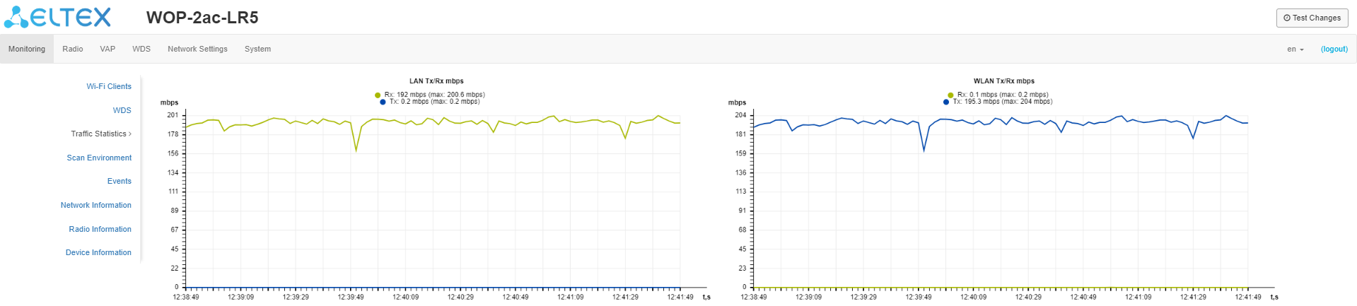
The LAN Tx/Rx diagram shows the speed of the traffic transmission/reception via the access point's Ethernet interface in last 3 minutes. The The diagram is automatically updated every 2 seconds.
The WLAN Tx/Rx diagram shows the speed of the traffic transmission/reception via the access point's Radio interfaces in last 3 minutes. The diagram is automatically updated every 2 seconds.
| Scroll Pagebreak |
|---|
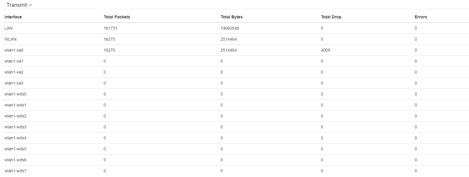
'Transmit' table description:
- Interface — name of the interface;
- Total Packets – number of successfully sent packets;
- Total Bytes – number of successfully sent bytes;
- Total Drop – number of rejected packets;
- Errors – number of errors.
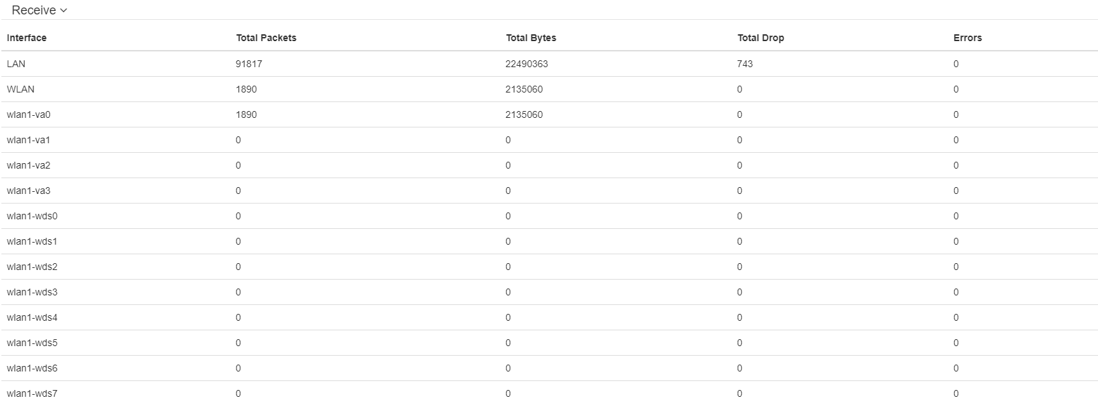
'Receive' table description:
- Interface – name of the interface;
- Total Packets – number of successfully received packets;
- Total Bytes – number of successfully received bytes;
- Total Drop – number of rejected packets;
- Errors – number of errors.
| Scroll Pagebreak |
|---|
The 'Scan Environment' submenu
In the 'Scan Environment' submenu, the radio environment scanning and neighboring access points detection are carried out.
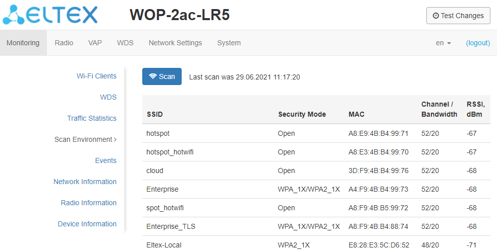
After clicking on the 'Scan' button, the process will be launched. After the scan is completed, a list of detected access points and information about them will appear:
- SSID – SSID of the detected access point;
- Security Mode – security mode of the detected access point;
- MAC – MAC address of the detected access point;
- Channel/Bandwidth – radio channel on which the detected access point operates;
- RSSI – the level with which the device receives the signal of the detected access point, dBm.
| Подсказка |
|---|
Please note that during the environment scanning, the device’s radio interface will be disabled, which will make it impossible to transfer data to Wi-Fi clients. |
| Scroll Pagebreak |
|---|
The 'Events' submenu
In this section, you can view a list of real-time informational messages which contains the following information:
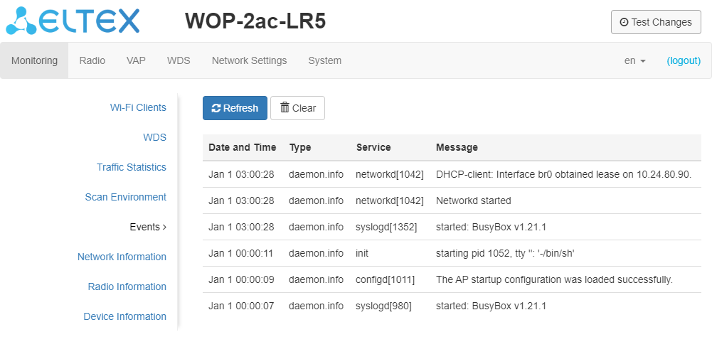
- Date and Time – time when the event was generated;
- Type – category and importance level of the event;
- Service – name of the process that generated the message;
- Message – event description.
Level | Message importance level | Description |
|---|---|---|
0 | Emergency | A critical error has occurred in the system, the system can go wrong. |
1 | Alert | Immediate intervention in the system is required. |
2 | Critical | A critical error has occurred in the system. |
3 | Error | An error has occurred in the system. |
4 | Warning | Warning, non-emergency message. |
5 | Notice | System notice, non-emergency message. |
6 | Informational | Informational system messages. |
7 | Debug | Debugging messages provide the user with information for correct system configuration. |
| Scroll Pagebreak |
|---|
The 'Network Information' submenu
In the 'Network Information' submenu common network settings of the device can be viewed.
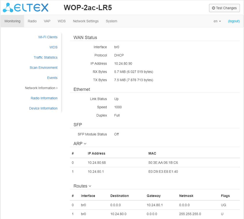
WAN Status:
- Interface – name of the bridge interface;
- Protocol – a protocol used to access the WAN;
- IP address – device IP address in external network;
- RX Bytes – number of bytes received on WAN;
- TX Bytes – number of bytes sent from WAN;
Ethernet:
- Link Status – Ethernet port status;
- Speed – Ethernet port connection speed;
- Duplex – data transfer mode:
- Full – full duplex;
- Half – half duplex.
SFP
- SFP-module Status – indicates presence/absence of SFP module;
- Link Status – optical interface operation status;
- Tx Fault – transceiver failure indication;
- LOS – signal loss;
- Speed – data transfer rate;
- Temperature – current temperature of the SFP module;
- Voltage – SFP module supply voltage;
- Current – SFP module laser bias current;
- Emission power – transceiver output power;
- Receiver power – receiver input power.
ARP
The ARP table contains information about mapping of neighboring network devices' IP and MAC addresses:
- IP address – device IP address;
- MAC – device MAC address.
Routes:
- Interface – name of the bridge interface;
- Destination– IP address of destination host or subnet that the route is established to;
- Gateway – IP address of a gateway used for the access to the Destination;
- Netmask – subnet mask;
- Flags – certain route characteristics. The following flag values exist:
- U – means that the route is created and passable;
- H – identifies the route to the specific host;
- G – means that the route lies through the external gateway. System network interface provides routes to networks with direct connection. All other routes lie through external gateways. G flag is used for all routes except for the routes to the direct connection networks.
- R – indicates that the route was most likely created by a dynamic routing protocol running on the local system using the reinstate parameter;
- D – indicates that the route was added as a result of receiving an ICMP Redirect Message. When the system learns the route from the ICMP Redirect message, the route will be added into the routing table in order to prevent redirection of the following packets intended for the same destination.
- M – means that the route was modified – likely by a dynamic routing protocol running on a local system with the 'mod' parameter applied;
- A – points to a buffered route, which an entry in the ARP table corresponds to.
- C – means that the core routing buffer is the route source;
- L – indicates that one of the addresses of the computer is the route destination. Such "local routes" exist in the routing buffer only.
- B – indicates that a broadcasting address is the route destination. Such "broadcast routes" exist in the routing buffer only.
- I – indicates that the route is connected to a ring (loopback) interface for a purpose other than to access the ring network. Such 'internal routes' exist in the routing buffer only.
- ! – means that datagrams sent to the address will be rejected by the system.
Scroll Pagebreak
The 'Radio Information' submenu
In the 'Radio Information' submenu the current status of WOP-2ac-LR5 radio interface is displayed.
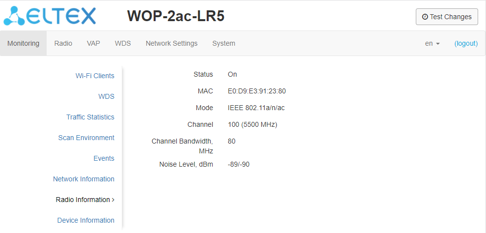
The access point radio interfaces can be in two states: 'On' and 'Off'. The Radio status depends on whether the radio interface has virtual access points (VAPs) or wireless bridges (WDS) enabled. In case there is at least one active VAP or configured WDS on the radio interface, Radio will be in the 'On' status, otherwise - 'Off'.
Depending on the Radio status, the following information is available for monitoring:
'Off':
- Status – radio interface state;
- MAC – radio interface MAC address;
- Mode – radio interface operation mode according to IEEE 802.11 standards.
'On':
- Status – radio interface state;
- MAC – radio interface MAC address;
- Mode – radio interface operation mode according to IEEE 802.11 standards;
- Channel – number of the wireless channel on which the radio interface is running;
- Channel Bandwidth – bandwidth of the channel on which the radio interface is running, MHz;
- Noise Level – level of the noise in the radio channel, dBm.
Scroll Pagebreak
The 'Cluster Synchronization' submenu
This submenu contains information about the status of the inter-sectoral synchronization (ISS) and all cluster members.
| Подсказка |
|---|
The submenu is only available for WOP-2ac-LR5 SYNC devices. |
Possible status values:
- Running – transmission synchronization process is started between the BSs;
- Waiting cluster ready – the process of waiting for all cluster members to be ready to start synchronization;
- Disabled – ISS is disabled in the base station settings.
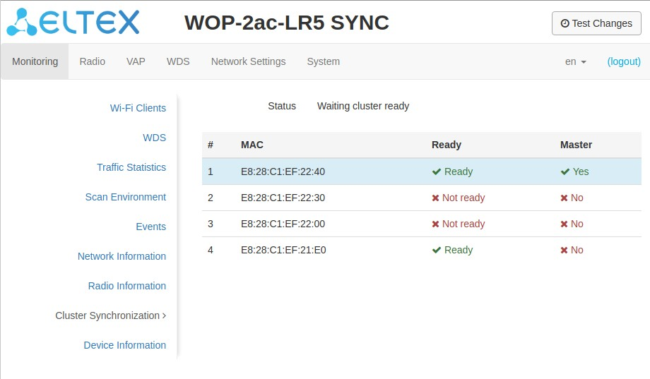
Information on cluster members:
- # – number in the list;
- MAC – MAC addresses of base stations included in a given ISS cluster;
- Ready – readiness state of the cluster member. Possible states:
- Ready – this BS has communication with all other cluster members and is ready to start the synchronization process;
- Not ready – this BS has no connection with at least one other cluster member, which is specified in its configuration on the Radio/Synchronization page.
- Master – flag defining the master in the ISS cluster.
The line with the information about the specified BS is highlighted in blue.Scroll Pagebreak
The 'Device Information' submenu
The 'Device Information' submenu displays main WOP-2ac-LR5 parameters.
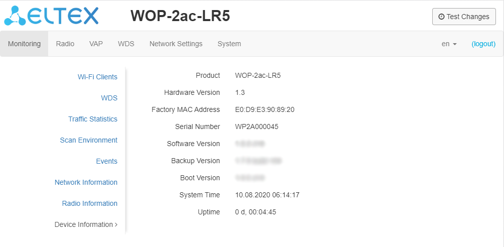
- Product – device model name;
- Hardware Version – device hardware version;
- Factory MAC Address – device WAN interface MAC address set by the manufacturer;
- Serial Number – device serial number set by manufacturer;
- Software Version – device firmware version;
- Backup Version – previously installed firmware version;
- Boot Version – device bootloader firmware version;
- System Time – current time and date set in system;
- Uptime – the time since the last time the device was turned on or restarted.
Scroll Pagebreak
The 'Radio' menu
In the 'Radio' menu the wireless interface can be configured.
The 'Radio' submenu
In the 'Radio' submenu, the device radio interface's parameters are configured.
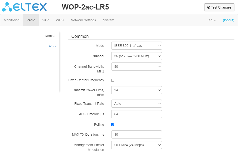
- Mode – interface operation mode:
- IEEE 802.11a
- IEEE 802.11a/n
- IEEE 802.11a/n/ac
- Channel – data channel selection;
- Channel Bandwidth, MHz – bandwidth of a channel on which the base station operates. The parameter may take values of 5, 10, 20, 40 and 80 MHz. Note that channel bandwidth of 80 MHz will operate only according to 802.11ac standard. If the base station has 5 or 10 MHz bandwidth, select the same bandwidth on the user station;
- Fixed center frequency – when the flag is checked, all traffic (data and management packets) will be transmitted at the specified channel center frequency with a given bandwidth (40 or 80 MHz). The function is proprietary, transmission is not carried out according to IEEE 802.11 standards, where it is supposed to use different center frequencies for data and management traffic with 40/80 MHz bandwidth;
- Tx Power (dBm) – Wi-Fi transmitter signal strength adjustment, dBm;
- Fixed Transmit Rate – fixed wireless data transmission rate defined by IEEE 802.11a/n/ac standards;
- ACK Timeout , µ s – waiting time for packet delivery confirmation from the subscriber;
- Polling – when checked, the option is enabled, otherwise – disabled. Polling is an option for TDM access to the medium (time division). It is characterized by a constant customer survey by the BS:
- MAX TX Duration, ms – time indicating how long the subscriber station can transmit traffic;
- Management packet modulation – fixed rate for management packets.
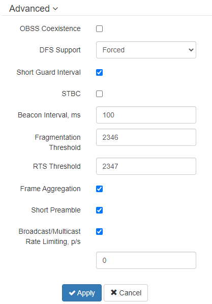
In the 'Advanced' submenu, additional parameters of the device’s radio interface are configured.
- OBSS Coexistence – automatic channel bandwidth reduction mode when the environment is loaded. When the flag is set, the mode is enabled;
- DFS Support – dynamic frequency selection mechanism. The mechanism requires wireless devices scan environment and avoid using channels that coincide with channels on which radiolocation systems operate at 5 GHz:
- Disabled – the mechanism is disabled. DFS channels are not available for selection;
- Enabled – the mechanism is enabled;
- Forced – the mechanism is disabled. DFS channels are available for selection.
- Short Guard Interval – support for Short Guard interval. Access point transmits data using 400 ns Guard interval (instead of 800 ns) to clients that also support Short GI;
- STBC – Space-Time Block Coding method dedicated to improve data transmission reliability. The field is available only if the selected mode of radio interface operation includes 802.11n. When checked, the device transmits one data flow through several antennas. When unchecked, the device does not transmit one data flow through several antennas.
- Beacon Interval, ms – beacon frames transmission period. The frames are sent to detect access points. The parameter takes values from 20 to 2000 ms, by default – 100 ms;
- Fragmentation Threshold – frame fragmentation threshold, bytes. The parameter takes values 256-2346, by default – 2346;
- RTS Threshold – specifies the number of bytes after which the transmission request will be sent (Request to Send). Decreasing the parameter's value might improve access point operation when there are a lot of clients connected. However, it will reduce general bandwidth of a wireless network. The parameter takes values from 0 to 2347, by default – 2347;
- Frame Aggregation – enable support for AMPDU/AMSDU;
- Short Preamble – use of the packet short preamble;
- Broadcast/Multicast Rate Limiting, p/s – when the flag is set, transmission of broadcast/multicast traffic over the wireless network is restricted. Specify the limit for broadcast traffic in the opened window (packets per second).
To apply a new configuration and save settings to non-volatile memory, click 'Apply'. Click 'Cancel' to discard the changes.
| Scroll Pagebreak |
|---|
The 'QoS' submenu
In the 'QoS' submenu, Quality of Service functions are configured.
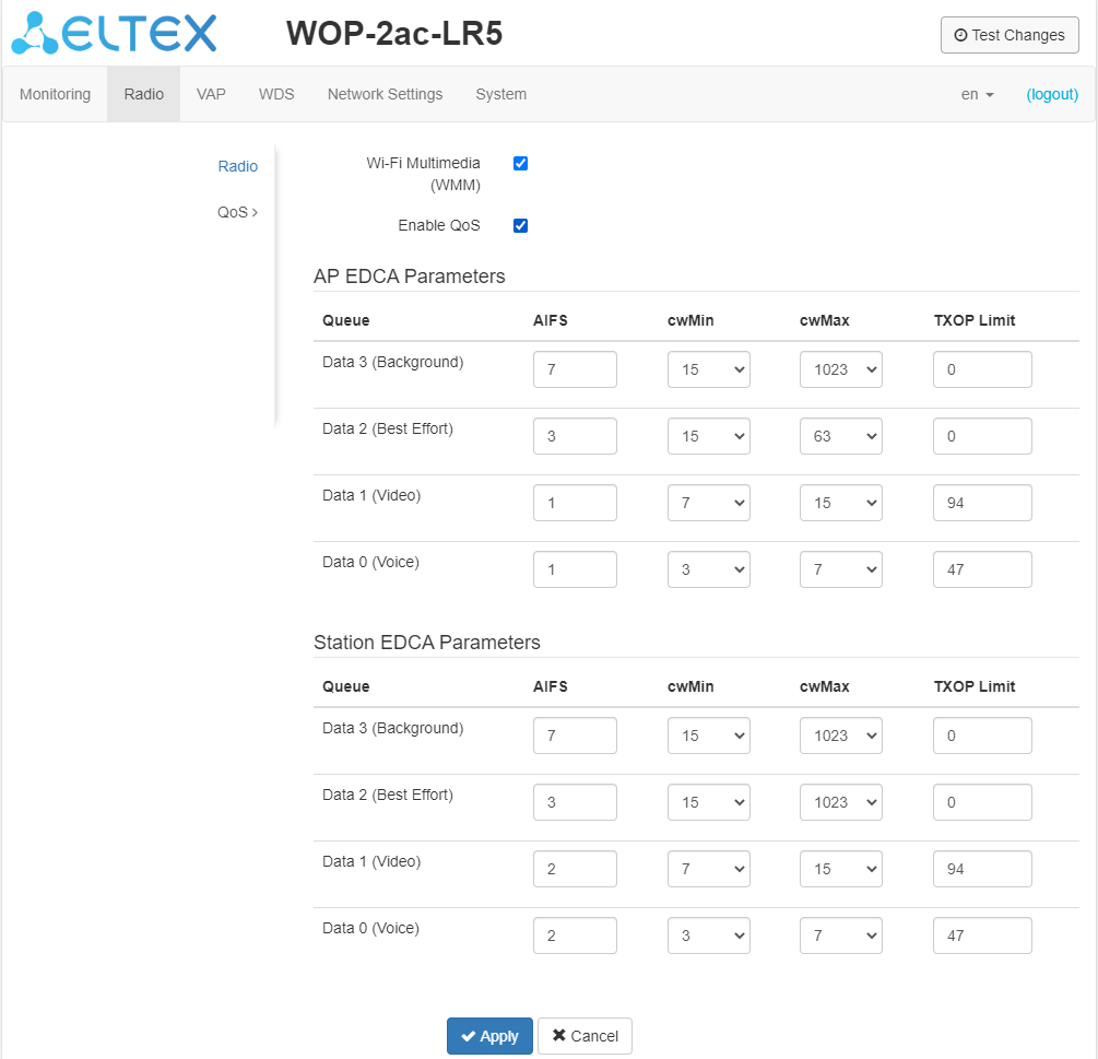
- WMM – enabling WMM support (Wi-Fi Multimedia);
- Enable QoS – when the flag is selected, EDCA parameters configuration is available;
- AP EDCA parameters – access point settings table (traffic is transmitted from the access point to the client):
- Queue – predefined queues for various kinds of traffic:
- Data 3 (Background) – low priority queue, high bandwidth (802.1p: cs1, cs2 priorities);
- Data 2 (Best Effort) – middle priority queue, middle bandwidth and delay; Most of the traditional IP data is sent to this queue (802.1p: cs0, cs3 priorities);
- Data 1 (Video) – high priority queue, minimal delay. In this queue, time-sensitive video data is automatically processed (802.1p: cs4, cs5 priorities);
- Data 0 (Voice) – high priority queue, minimal delay. In this queue, time sensitive data is automatically processed, such as: VoIP, streaming video (802.1p: cs6, cs7 priorities).
- AIFS – Arbitration Inter-Frame Spacing, defines the waiting time of data frames, measured in slots, takes values (1-255);
- cwMin – the initial timeout value before resending a frame, specified in milliseconds, takes the values 1, 3, 7, 15, 31, 63, 127, 255, 511, 1023. The value of cwMin cannot exceed the value of cwMax;
- cwMax – the maximum timeout value before resending a frame, specified in milliseconds, takes the values 1, 3, 7, 15, 31, 63, 127, 255, 511, 1023. The value of cwMax must exceed the value of cwMin;
- TXOP Limit – this parameter is used only for data transmitted from the client station to the access point. The transmission capability is the time interval, in milliseconds, when the client WME station has the rights to initiate data transmission over the wireless medium to the access point, the maximum value is 65535 milliseconds;
- Queue – predefined queues for various kinds of traffic:
- Station EDCA parameters – table of client station settings (traffic is transmitted from the client station to the access point). Table fields are described above.
To apply a new configuration and save settings to non-volatile memory, click 'Apply'. Click 'Cancel' to discard the changes.
The 'Synchronization' submenu
| Подсказка |
|---|
This menu is available for WOP-2ac-LR5 SYNC only. |
Contains settings of inter-sectoral synchronization (ISS) for base stations.
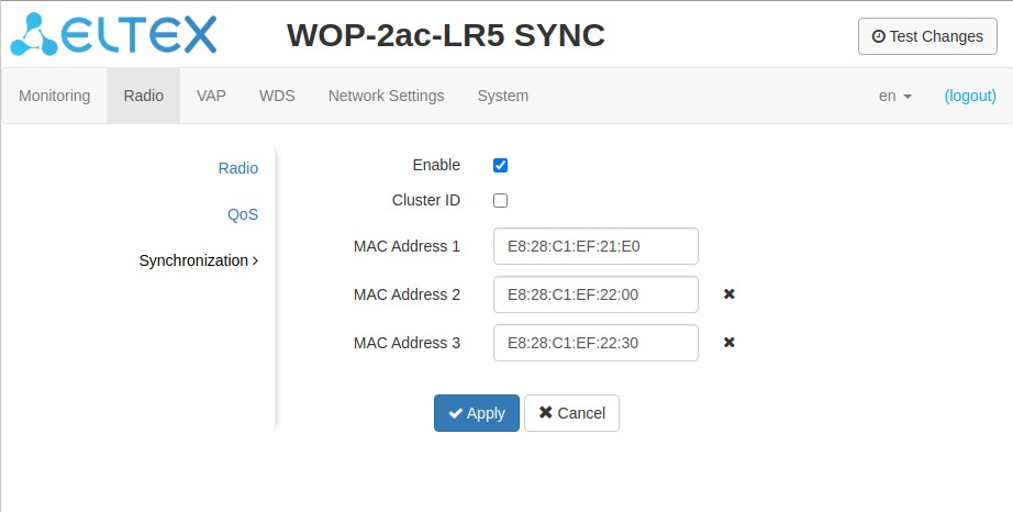
- Enable – when checked, ISS mechanism is enabled, otherwise – disabled;
- Cluster ID – base station cluster ID. By default – 0. Used to organize several clusters within one L2 segment to identify control packets of BS ISS included in one cluster;
- MAC address 1..3 – MAC addresses of other base stations included in the given ISS cluster.
To apply a new configuration and save settings to non-volatile memory, click 'Apply'. Click 'Cancel' to discard the changes.
| Scroll Pagebreak |
|---|
The 'VAP' menu
In the 'VAP' menu, virtual Wi-Fi access points (VAP) are configured.
The 'Summary' submenu
The 'Summary' submenu displays the settings of all VAPs. You can see the settings of each virtual access point in sections VAP0..3.
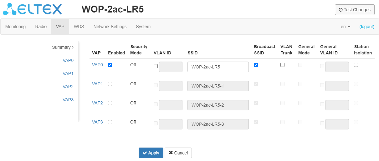
- VAP0..3 – the sequence number of the virtual access point;
- Enabled – when checked, the virtual access point is enabled, otherwise it is disabled;
- Security Mode – the type of data encryption used on the virtual access point;
- VLAN ID – number of VLAN from which the tag will be removed when transmitting Wi-Fi traffic to clients connected to this VAP. When traffic flows in the opposite direction, untagged traffic from clients will be tagged with VLAN ID (when VLAN Trunk mode is disabled);
- SSID – virtual wireless network name;
- Broadcast SSID – when checked, SSID broadcasting is on, otherwise it is disabled;
- VLAN Trunk – when the flag is set, tagged traffic is transmitted to the subscriber;
- General Mode – when the flag is set, transmission of untagged traffic jointly with tagged traffic is allowed (available when Trunk VLAN mode is enabled);
- General VLAN ID – a tag will be removed from the specified VLAN ID and the traffic of this VLAN will pass to the client without a tag. When traffic passes in the opposite direction, untagged traffic will be tagged with General VLAN ID;
- Station Isolation – when checked, traffic isolation between clients on the same VAP is enabled.
To apply a new configuration and save setting to non-volatile memory, press 'Apply'. Press 'Cancel' to discard the changes.
The 'VAP' submenu
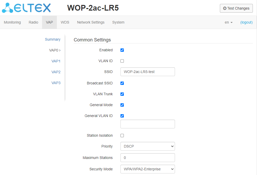
Common Settings
- Enabled – when checked, the virtual access point is enabled, otherwise it is disabled;
- VLAN ID – number of VLAN from which the tag will be removed when transmitting Wi-Fi traffic to clients connected to this VAP. When traffic flows in the opposite direction, untagged traffic from clients will be tagged with VLAN ID (when VLAN Trunk mode is disabled);
- SSID – virtual wireless network name;
- Broadcast SSID – when checked, SSID broadcasting is on, otherwise it is disabled;
- VLAN Trunk – when the flag is set, tagged traffic is transmitted to the subscriber;
- General Mode – when the flag is set, transmission of untagged traffic jointly with tagged traffic is allowed (available when Trunk VLAN mode is enabled);
- General VLAN ID – a tag will be removed from the specified VLAN ID and the traffic of this VLAN will pass to the client without a tag. When traffic passes in the opposite direction, untagged traffic will be tagged with General VLAN ID;
- Station Isolation – when checked, traffic isolation between clients on the same VAP is enabled.
- Priority – prioritization method. Specifies the field on the basis of which traffic transmitted to the radio interface will be allocated to the WMM queues:
- DSCP – will analyze the priority from the DSCP field of the IP packet header; if the DSCP value in tagged packets is 0, then the priority from the CoS field (802.1p) will be analyzed;
- 802.1p – will analyze the priority from the CoS (Class of Service) field of the tagged packets; if the priority is overridden by VLAN mapping rules, the priority set for transmissions to the radio channel will be analyzed.
- Maximum Stations – the maximum number of clients connected to the virtual network;
- Security Mode – wireless access security mode:
- Off – do not use encryption for data transfer. The access point is available for any subscriber to connect;
- WPA, WPA2, WPA/WPA2 – encryption methods for which the following setting will be available:
- WPA Key – key/password required to connect to the virtual access point. The length of the key is from 8 to 63 characters;
- WPA-Enterprise, WPA2-Enterprise, WPA/WPA2-Enterprise – wireless channel encryption mode, according to which the client is authorized on the centralized RADIUS server. To configure this security mode, you must specify the parameters of the RADIUS server. You also need to specify a key for the RADIUS server. If you select one of the methods, the RADIUS server parameters configuration will be available:
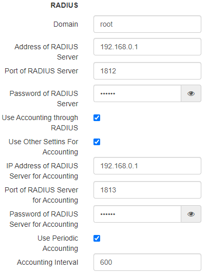
- Domain – user domain;
- IP Address of RADIUS Server – RADIUS server address;
- Port of RADIUS Server – port of the RADIUS server used for authentication and authorization;
- Password of RADIUS Server – password for the RADIUS server used for authentication and authorization;
- Use Accounting through RADIUS – when checked, 'Accounting' messages will be sent to the RADIUS server;
- Use Other Settings For Accounting
- IP Address of RADIUS Server for Accounting – address of the RADIUS server used for accounting;
- Port of RADIUS Server for Accounting – port that will be used for accounting on the RADIUS server;
- Password of RADIUS Server for Accounting– password for the RADIUS server used for accounting;
- Use Periodic Accounting – enable periodic sending of 'Accounting' messages to the RADIUS server. You can set the interval for sending messages in the 'Accounting Interval' field.
Scroll Pagebreak

Shapers
- Show – display configuration field;
- VAP Limit Down – restriction of bandwidth in the direction from the access point to the clients (in total) connected to the VAP, Kbps;
- VAP Limit Up – restriction of bandwidth in the direction from the clients (in total) connected to the VAP, to the access point, Kbps;
- STA Limit Down – restriction of bandwidth in the direction from the access point to the clients (each individually) connected to the VAP, Kbps;
- STA Limit Up – restriction of bandwidth in the direction from the clients (each individually) connected to the VAP, to the access point, Kbps.
MAC ACL
This subsection configures lists of MAC addresses of clients that, depending on the access policy selected, are allowed or denied to connect to this VAP.

- Enabled – when checked, the selected access policy will work;
- Policy – access policy. Possible values:
- Deny – clients whose MAC addresses are listed will not be allowed to connect to this VAP. Everyone else will be allowed access to this VAP;
- Allow – clients whose MAC addresses are listed will be allowed to connect to this VAP. Everyone else will be denied access.
- List of MAC Addresses – list of MAC addresses of clients that are allowed or denied access to this VAP. May contain up to 128 addresses.
To add the address to the list click the ![]() button and in the displayed field, enter the MAC address. To delete the address from the list, click the
button and in the displayed field, enter the MAC address. To delete the address from the list, click the ![]() button in the corresponding line.
button in the corresponding line.
If you need to add to the list the MAC address of a client that is currently connected to the base station, click the
![]() button at the end of the line and select the desired address from the list, it will be automatically added to the field.
button at the end of the line and select the desired address from the list, it will be automatically added to the field.
By default, up to 10 addresses are displayed in the list. To see the full list if it contains more than 10 addresses, click 'Show all'.

To apply a new configuration and save settings to non-volatile memory, click 'Apply'. Click 'Cancel' to discard the changes.
The 'WDS' menu
In the 'WDS' menu, wireless bridges are configured for WOP-2ac-LR5.
| Подсказка |
|---|
When configuring a WDS connection, the same channel and channel width should be selected in the radio interface settings of devices that will be connected via WDS. |
The 'WDS' submenu
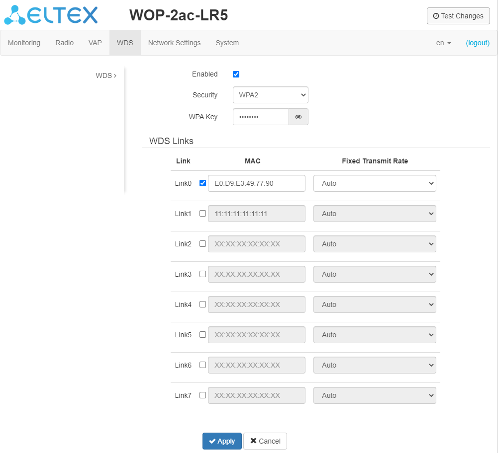
- Enabled – when the flag is set, the wireless bridge mode is enabled; otherwise, it is disabled;
- Security – wireless network access security mode:
- Off – do not use encryption for data transfer;
- WPA2 – encryption method for which the following setting is available:
- WPA Key – key/password required to connect to the opposite access point. The key length is from 8 to 63 characters.
- Link X (where X=0..7) – enable wireless bridge link;
- MAC – MAC address of the opposite device to which the wireless bridge is configured;
- Fixed Transmit Rate – fixed wireless data transmission rate which defined by IEEE 802.11a/n/ac standards and selected individually for each link.
To apply the new configuration and save the settings to the non-volatile memory, click 'Apply'. To cancel the changes click the 'Cancel' button.
The 'Network Settings' menu
The 'System Configuration' submenu

- Hostname – network name of the device specified by a string from 1 to 63 characters; latin uppercase and lowercase letters, numbers, hyphen '-' (hyphen can not be the last character in the name);
- Management VLAN:
- Disabled – Management VLAN is not used;
- Terminating – the mode where the management VLAN is terminated at the access point; in this case, clients connected via the radio interface do not have access to this VLAN;
- Forwarding – the mode where the management VLAN is also transmitted to the radio interface (with the appropriate VAP configuration).
- VLAN ID – the VLAN ID used to access the device, takes values 1-4094;
- Protocol – protocol that will be used to connect the device to service provider network via Ethernet interface:
- DHCP– operation mode where IP address, subnet mask, DNS server address, defualt gateway and other parameters required for operation are obtained from DHCP server automatically;
- Static – operation mode where IP address and all the necessary parameters for WAN interface are assigned statically. If 'Static' is selected, the following parameters will be available to configure:
- Static IP – device WAN interface IP address in the provider network;
- Netmask – external subnet mask;
- Gateway – address to which a packet is sent, if the route has not been found in a routing table;
- Primary DNS Server, Secondary DNS Server – IP addresses of DNS servers. If DNS servers' addresses are not allocated automatically via DHCP, set them manually.
To apply a new configuration and save settings to non-volatile memory, click 'Apply'. Click 'Cancel' to discard the changes.
The 'Access' submenu
In the 'Access' submenu, access to the device via the web interface, Telnet, SSH, NETCONF and SNMP is configured.
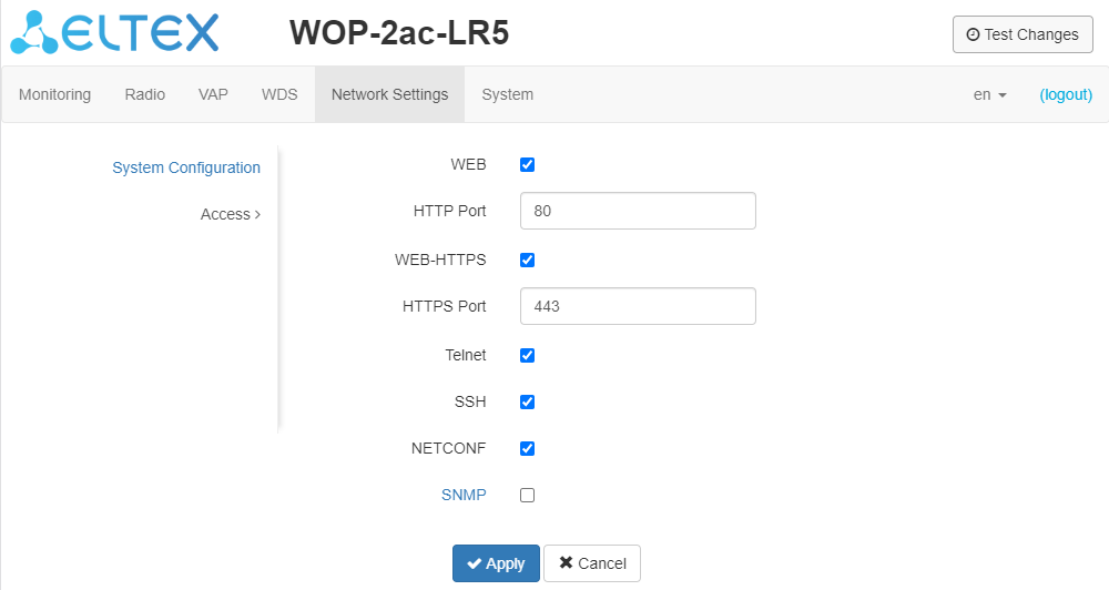
- To enable HTTP access to the device via the web interface via HTTP protocol, set the flag in front of 'WEB'. In the opened window, it is possible to change the HTTP port (by default, 80). In addition to the default one, ports can take values from 1025 to 65535 inclusive;
- To enable access to the device via the web interface via HTTPS protocol, set the flag in front of 'WEB-HTTPS'. In the opened window, it is possible to change the HTTPS port (by default, 443). In addition to the default one, ports can take values from 1025 to 65535 inclusive;
| Подсказка |
|---|
Note that the ports for the HTTP and HTTPS protocols should not have the same value. |
- To enable access to the device via Telnet, select the checkbox in front of 'Telnet';
- To enable access to the device via SSH, select the checkbox in front of 'SSH';
- To enable access to the device via NETCONF, select the checkbox in front of 'NETCONF';
WOP-2ac-LR5 software allows device status and sensors monitoring via SNMP. The device has support for SNMPv1, SNMPv2.
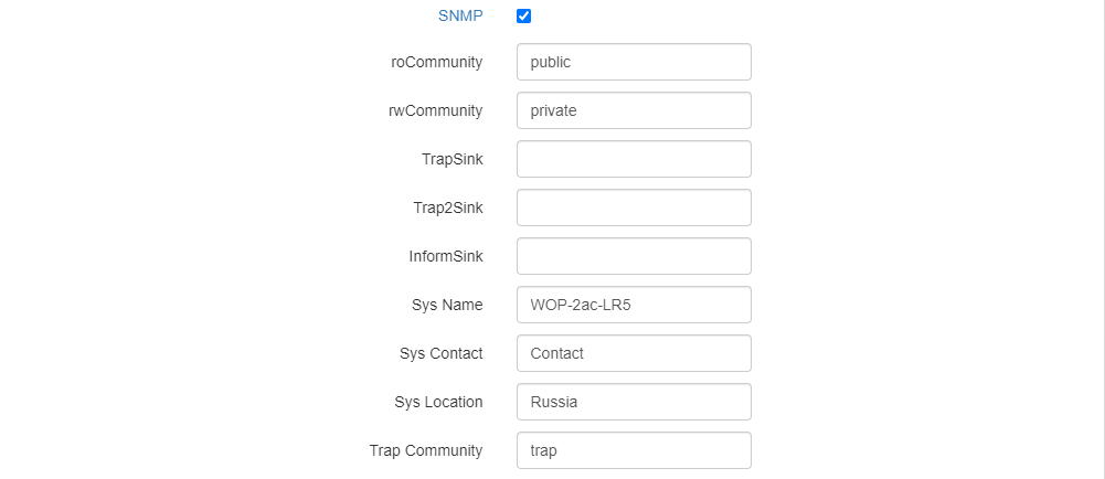
To change the SNMP agent parameters, select the checkbox in front of 'SNMP'. After this the following parameters will become available.
- roCommunity – a password to read the parameters (by default: public);
- rwCommunity – a password to configure (write) parameters (by default: private);
- TrapSink – IP address or domain name of SNMPv1-trap message recipient in HOST [COMMUNITY [PORT]] format;
- Trap2Sink – IP address or domain name of SNMPv2-trap message recipient in HOST [COMMUNITY [PORT]] format;
- InformSink – IP address or domain name of Inform message recipient in HOST [COMMUNITY [PORT]] format;
- Sys Name – device name;
- Sys Contact – device vendor contact information;
- Sys Location – device location information;
- Trap community – password contained in traps (default value: trap).
The list of objects available for reading and configuring via SNMP is given below:
- eltexLtd.1.127.1 – monitoring of BS parameters and connected APs;
- eltexLtd.1.127.3 – BS management (reboot).
where eltexLtd – 1.3.6.1.4.1.35265 is Eltex Enterprise identifier.
To apply a new configuration and save settings to non-volatile memory, click 'Apply'. Click 'Cancel' to discard the changes.
| Scroll Pagebreak |
|---|
The 'System' menu
In 'System' submenu, configuration of system, time, syslog as well as password change, configuration upload/download, firmware update and device reboot can be performed.
The 'Device Firmware Upgrade' submenu
The 'Device Firmware Upgrade' submenu is used to update the device firmware.
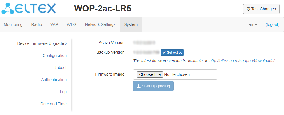
- Active Version – firmware version installed on the device and operating at the moment;
- Backup Version – firmware version installed on the device which can be used in case of problems without downloading a firmware file;
- Set Active – a button that makes a backup version of the firmware active; this will require a reboot of the device. The active firmware version will be set as a backup.
Firmware update
Download the firmware file from http://eltex-co.com/support/downloads/ and save it to your computer. To do this, click the 'Choose file' button in the Firmware Image field and specify the path to the firmware file in .tar.gz format.
To start the update process, click the 'Start Upgrading' button. The process may take several minutes (its current status will be shown on the page). The device will be automatically rebooted when the update is completed.
| Предупреждение |
|---|
Do not switch off or reboot the device during the firmware update. In case of upgrading from firmware version 1.2.0 to 1.3.0 firmware version, it is necessary to reset the device to factory settings and reconfigure it according to the usage pattern after the firmware update. If the firmware is rolled back from version 1.4-1.9 to the 1.3 or lower version, the configuration of the radio interface may be incompatible, therefore, it will be changed. Perform the setup again and then enable the VAP/SSID. |
| Scroll Pagebreak |
|---|
The 'Configuration' submenu
In the 'Configuration' submenu current configuration can be saved and restored.
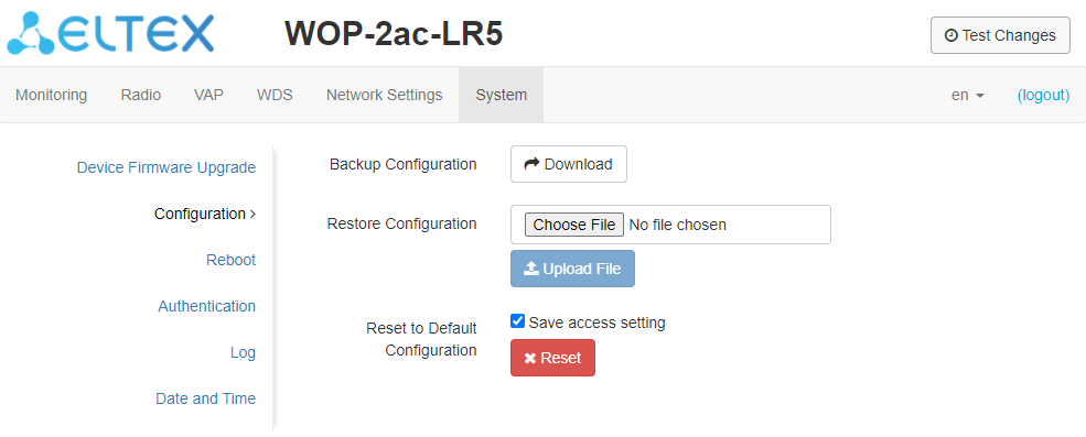
Backup Configuration
To save current device configuration to a local computer, click the 'Download' button.
Restore Configuration
To upload the configuration file saved on a local computer, use Restore Configuration. To upload the device configuration, click the 'Choose file' button, specify a file (in .tar.gz format) and click the 'Upload File' button. Uploaded configuration will be applied automatically without device reboot.
| Подсказка |
|---|
Note that all the passwords of configuration are encrypted with a key depending on device MAC address. Before transfering configuration from one device to another, reset all passwords. |
To change the passwords, open the configuration file in text editor and edit them. Then save the changes in configuration archive. The example of password changing is shown below:
| Блок кода |
|---|
"authentication":{
  "admin-password":"encrypted:7068747570617169"
},
changes to
"authentication":{
  "admin-password":"password"
}, |
Reset to Default Configuration
To reset all the settings to default values, click 'Reset' button. If the checkbox 'Save access setting' is selected, configuration parameters that are responsible for access to the device (IP address settings, Telnet/SSH/SNMP/Netconf/WEB access settings) will be saved.
| Scroll Pagebreak |
|---|
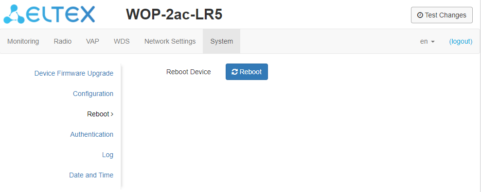
The 'Reboot' submenu
To reboot the device, click the 'Reboot' button. The device reboot process takes about 1 minute.
The 'Authentication' submenu
The 'Authentication' submenu is used to configure user authentication.
| Подсказка |
|---|
Factory account to access the device: login: admin, password: password. |
It is also possible to create additional accounts with the roles of administrator or viewer (configuration is only available through the CLI). Accounts with the role of administrator have full access to the device: reading and writing any settings, full monitoring of the device status. Accounts with the viewer role have only monitoring access.
The 'Local Password' section is used to change the factory default password for the admin account. This password is stored on the access point. To change the password, enter the new password first in the 'Password' field, then in the 'Confirm Password' field and click 'Apply' in this section to save the new password.
The 'RADIUS Authentication' section configures access to the RADIUS server that will be used to authenticate and authorize the AP user.
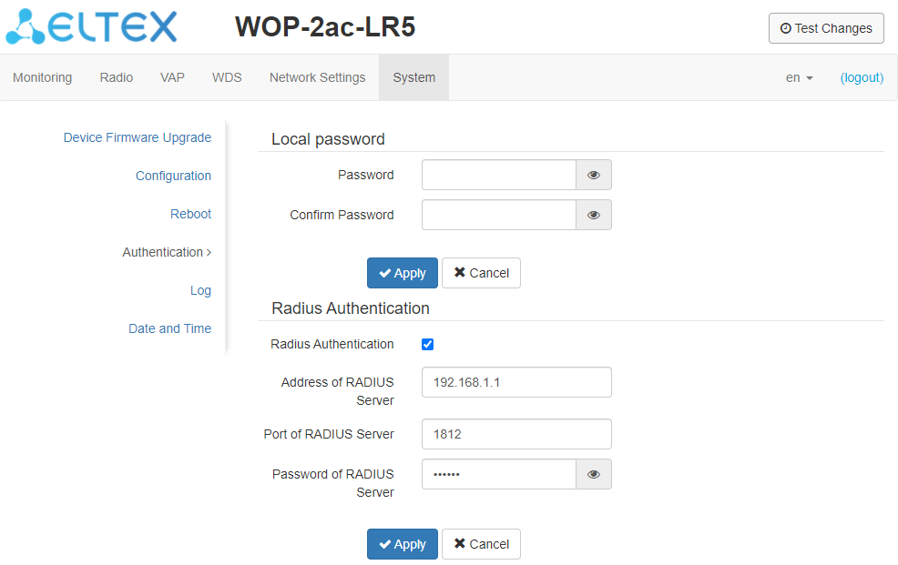
- RADIUS Authentication – when this flag is checked, authentication will be performed by the account on the RADIUS server;
- Address of RADIUS Server – RADIUS server IP address;
- Port of RADIUS Server – RADIUS server port, which is used for authentication and authorization;
- Password of RADIUS Server – RADIUS server key, which is used for authentication and authorization.
To apply a new configuration and save settings to non-volatile memory, click 'Apply'. Click 'Cancel' to discard the changes.
When authenticating via RADIUS server, you should create a local account, which is the same as the account on the RADIUS server. The configuration is performed through the CLI. For details see section 'Additional users creation'.
| Подсказка |
|---|
If RADIUS authentication is enabled, but the server is unavailable, authentication will be performed using the local account. |
Scroll Pagebreak
The 'Log' submenu
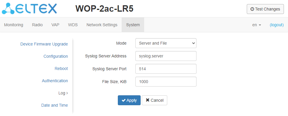
The 'Log' submenu is intended to configure the output of different system debugging messages in order to detect causes of the device operation problems.
- Mode – Syslog agent operation mode:
- Local File – log information is stored in a local file and is available in the device’s web interface in the 'Monitoring/Events' tab;
- Server and File – log information is sent to a remote Syslog server and stored in a local file.
- Syslog Server Address – IP address or domain name of the Syslog server;
- Syslog Server Port – port for incoming Syslog server messages (default: 514, valid values: from 1 to 65535);
- File Size, KiB – maximum size of the log file (valid values: 1-1000 KiB).
The 'Date and Time' submenu
In the 'Date and Time' submenu, you can set the time manually or using the time synchronization protocol (NTP).
Manual:
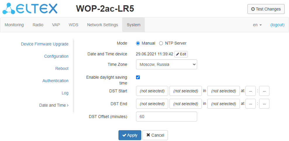
- Date and Time device – date and time set on the device. Click the 'Edit' button if the correction is necessary;
- Date, Time – set the current date and time or click the 'Set current date and time' button to set the PC time on the device;
- Time Zone – allows setting the timezone according to the nearest city for your region from the specified list;
- Enable daylight saving time – when selected, automatic daylight saving change will be performed automatically within the defined time period:
- DST Start – day and time, when daylight saving time starts;
- DST End – day and time, when daylight saving time ends;
- DST Offset (minutes) – time period in minutes, by which time offset is performed.
NTP Server:
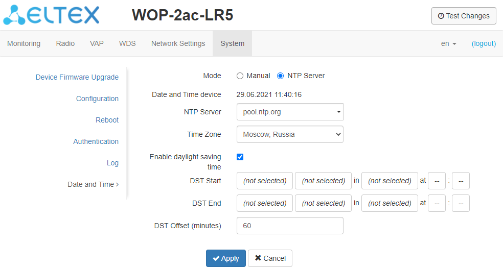
- Date and Time device – date and time set on the device;
- NTP Server – time synchronization server IP address/domain name. You can specify an address or select from the list;
- Time Zone – allows to set the timezone according to the nearest city for your region from the list;
To apply a new configuration and save settings to the non-volatile memory, click the 'Apply' button. To discard changes, click the 'Cancel' button.
Managing the device using the command line
| Подсказка |
|---|
To enter the configuration mode, enter the configure command. To display the existing settings of a particular configuration section, enter the show-config command. Press the key combination (English layout) – [Shift + ? ] to get a hint of what value this or that configuration parameter can take. To get a list of options available for editing in this configuration section, press the Tab key. To save the settings, enter the save command. To go back to the previous configuration section, enter the exit command. To exit the configuration mode, enter the end command. |
Connection to the device
By default, WOP-2ac-LR5 is configured to receive the address via DHCP. If this does not happen, you can connect to the device using the factory IP address.
| Подсказка |
|---|
WOP-2ac-LR5 factory default IP address: 192.168.1.10, subnet mask: 255.255.255.0. |
Connection to the device is performed via SSH/Telnet:
| панель | ||||||
|---|---|---|---|---|---|---|
| ||||||
ssh admin@<IP address of the device>, then enter the password telnet <IP address of the device>, enter login and password |
Network parameters configuration
| панель | ||||||||
|---|---|---|---|---|---|---|---|---|
| ||||||||
WOP-2ac-LR5(root):/# configure Adding static route: WOP-2ac-LR5(config):/interface/br0/common# exit |
| панель | ||||||||
|---|---|---|---|---|---|---|---|---|
| ||||||||
WOP-2ac-LR5(root):/# configure |
Network parameters configuration using the set-management-vlan-mode utility
| панель | ||||||||
|---|---|---|---|---|---|---|---|---|
| ||||||||
Obtain network parameters via DHCP: WOP-2ac-LR5(root):/# set-management-vlan-mode off protocol dhcp Static parameters: WOP-2ac-LR5(root):/# set-management-vlan-mode off protocol static-ip ip-addr X.X.X.X netmask Y.Y.Y.Y gateway Z.Z.Z.Z (where X.X.X.X - static IP address, Y.Y.Y.Y - subnet mask, Z.Z.Z.Z - gateway) |
| панель | ||||||||
|---|---|---|---|---|---|---|---|---|
| ||||||||
Obtain network parameters via DHCP: WOP-2ac-LR5(root):/# set-management-vlan-mode terminating vlan-id X protocol dhcp (where X - VLAN ID used for device access. Possible values: 1-4094) Static parameters: WOP-2ac-LR5(root):/# set-management-vlan-mode terminating vlan-id X protocol static-ip ip-addr X.X.X.X netmask Y.Y.Y.Y gateway Z.Z.Z.Z (where X - VLAN ID used for device access. Possible values: 1-4094, X.X.X.X - static IP address; Y.Y.Y.Y - subnet mask; Z.Z.Z.Z - gateway) |
| панель | ||||||||
|---|---|---|---|---|---|---|---|---|
| ||||||||
Obtain network parameters via DHCP: WOP-2ac-LR5(root):/# set-management-vlan-mode forwarding vlan-id X protocol dhcp (where X - VLAN ID used for device access. Possible values: 1-4094) Static parameters: WOP-2ac-LR5(root):/# set-management-vlan-mode forwarding vlan-id X protocol static-ip ip-addr X.X.X.X netmask Y.Y.Y.Y gateway Z.Z.Z.Z (where X - VLAN ID used for device access. Possible values: 1-4094, X.X.X.X - static IP address; Y.Y.Y.Y - subnet mask; Z.Z.Z.Z - gateway) |
| панель | ||||||||
|---|---|---|---|---|---|---|---|---|
| ||||||||
WOP-2ac-LR5(root):/# save (Save configuration) |
Scroll Pagebreak
Virtual Wi-Fi access points (VAP) configuration
The table shows the commands for configuring VAP security modes.
Table 4 – Commands for configuration of security mode on VAP
| Security mode | Command to set the security mode |
|---|---|
| Without password | security-mode off |
| WPA | security-mode WPA |
| WPA2 | security-mode WPA2 |
| WPA/WPA2 | security-mode WPA_WPA2 |
| WPA-Enterprise | security-mode WPA_1X |
| WPA2-Enterprise | security-mode WPA2_1X |
| WPA/WPA2-Enterprise | security-mode WPA_WPA2_1X |
Below are examples of VAP configuration with different security modes.
Configuration of VAP without encryption
| панель | ||||||||
|---|---|---|---|---|---|---|---|---|
| ||||||||
WOP-2ac-LR5(root):/# configure |
Configuration of VAP with WPA-Personal security mode
| панель | ||||||||
|---|---|---|---|---|---|---|---|---|
| ||||||||
WOP-2ac-LR5(root):/# configure |
Configuration of VAP with Enterprise authorization
| панель | ||||||||
|---|---|---|---|---|---|---|---|---|
| ||||||||
WOP-2ac-LR5(root):/# configure |
Advanced VAP settings
| панель | ||||||||
|---|---|---|---|---|---|---|---|---|
| ||||||||
WOP-2ac-LR5(config):/interface/wlan1-va0/vap# vlan-id X (where X - number of VLAN-ID on VAP) |
| панель | ||||||||
|---|---|---|---|---|---|---|---|---|
| ||||||||
WOP-2ac-LR5(config):/interface/wlan1-va0/vap# vlan-trunk true (Enabling VLAN trunk on VAP. To disable, enter false ) |
| панель | ||||||||
|---|---|---|---|---|---|---|---|---|
| ||||||||
WOP-2ac-LR5(config):/interface/wlan1-va0/vap# general-vlan-mode true (Enabling General VLAN on SSID. To disable, enter false ) |
| панель | ||||||||
|---|---|---|---|---|---|---|---|---|
| ||||||||
WOP-2ac-LR5(config):/interface/wlan1-va0/vap# hidden true (Enabling hidden SSID. To disable, enter false ) |
| панель | ||||||||
|---|---|---|---|---|---|---|---|---|
| ||||||||
WOP-2ac-LR5(config):/interface/wlan1-va0/vap# sta-limit X (where X - the maximum allowable number of clients connected to the virtual network) |
| панель | ||||||||
|---|---|---|---|---|---|---|---|---|
| ||||||||
WOP-2ac-LR5(config):/interface/wlan1-va0/vap# station-isolation true (Enable traffic isolation between clients within a single VAP. To disable, enter false ) |
| панель | ||||||||
|---|---|---|---|---|---|---|---|---|
| ||||||||
WOP-2ac-LR5(config):/interface/wlan1-va0/vap# shaper-per-sta-rx (Configuration of the shaper in the direction from the clients (each individually) connected to this VAP of the access point) |
| панель | ||||||||
|---|---|---|---|---|---|---|---|---|
| ||||||||
WOP-2ac-LR5(config):/interface/wlan1-va0/vap# priority-by-dscp false (Priority analysis from the CoS (Class of Service) field of tagged packets. Default value: true. In this case the priority from the DSCP field of the IP packet header is analyzed) |
| панель | ||||||||
|---|---|---|---|---|---|---|---|---|
| ||||||||
WOP-2ac-LR5(config):/interface/wlan1-va0/vap# acl |
| панель | ||||||||
|---|---|---|---|---|---|---|---|---|
| ||||||||
| WOP-2ac-LR5(config):/interface/wlan1-va0/vap# vlan-mapping WOP-2ac-LR5(config):/interface/wlan1-va0/vap/vlan-mapping# rule WOP-2ac-LR5(config):/interface/wlan1-va0/vap/vlan-mapping/rule# add name1 (where "name1" - mapping rule name. To remove the rule use the del command) WOP-2ac-LR5(config):/interface/wlan1-va0/vap/vlan-mapping/rule# name1 WOP-2ac-LR5(config):/interface/wlan1-va0/vap/vlan-mapping/rule/name1# eth-vlan-id X (where X - VLAN ID in Ethernet) WOP-2ac-LR5(config):/interface/wlan1-va0/vap/vlan-mapping/rule/name1# eth-priority X (where X - 802.1P priority when transmitting in Ethernet. Possible values: 0-7, auto. If priority is auto or not specified in this option - the original will be used) WOP-2ac-LR5(config):/interface/wlan1-va0/vap/vlan-mapping/rule/name1# wlan-vlan-id X (where X - VLAN ID in WLAN) WOP-2ac-LR5(config):/interface/wlan1-va0/vap/vlan-mapping/rule/name1# wlan-priority X (where X - 802.1P priority when transmitting in WLAN. Possible values: 0-7, auto. If priority is auto or not specified in this option - the original will be used) WOP-2ac-LR5(config):/interface/wlan1-va0/vap/vlan-mapping/rule/name1# exit WOP-2ac-LR5(config):/interface/wlan1-va0/vap/vlan-mapping/rule# exit WOP-2ac-LR5(config):/interface/wlan1-va0/vap/vlan-mapping# enable true (Enabling vlan-mapping. To disable enter false) |
Scroll Pagebreak
| панель | ||||||||
|---|---|---|---|---|---|---|---|---|
| ||||||||
General limitation of the number of groups for each client connected to a given VAP WOP-2ac-LR5(config):/interface/wlan1-va0/vap# multicast-group-limits Individual limitation of the number of groups for a particular client WOP-2ac-LR5(config):/interface/wlan1-va0/vap/multicast-group-limits# mac |
For all clients for which no individual limit is specified – the general limit on the number of groups set in the 'default-limit' will be applied.
| панель | ||||||||
|---|---|---|---|---|---|---|---|---|
| ||||||||
Configuring BPDU packet filtering for a specific VAP WOP-2ac-LR5(config):/interface/wlan1-va0# common Configuring BPDU packet filtering for the eth0 interface WOP-2ac-LR5(config):/interface/eth0# common |
Scroll Pagebreak
Radio configuration
To set the channel and change the power, use the following commands:
| панель | ||||||||
|---|---|---|---|---|---|---|---|---|
| ||||||||
WOP-2ac-LR5(root):/# configure |
Advanced Radio settings
| панель | ||||||||
|---|---|---|---|---|---|---|---|---|
| ||||||||
WOP-2ac-LR5(config):/interface/wlan1/wlan/radio# work-mode X (where X - radio interface operation mode according to IEEE 802.11. Possible values: a, an, ac) |
| панель | ||||||||
|---|---|---|---|---|---|---|---|---|
| ||||||||
| WOP-2ac-LR5(config):/interface/wlan1/wlan/radio# center-frequency true (Enabling fixed central frequency. To disable, enter false) |
| панель | ||||||||
|---|---|---|---|---|---|---|---|---|
| ||||||||
WOP-2ac-LR5(config):/interface/wlan1/wlan/radio# control-sideband lower (Parameter may take values: lower, upper. By default: lower) |
| панель | ||||||||
|---|---|---|---|---|---|---|---|---|
| ||||||||
WOP-2ac-LR5(config):/interface/wlan1/wlan/radio# sgi true (Enabling the use of a Short Guard Interval for data transmission of 400 ns instead of 800 ns. To disable, enter false ) |
| панель | ||||||||
|---|---|---|---|---|---|---|---|---|
| ||||||||
WOP-2ac-LR5(config):/interface/wlan1/wlan/radio# stbc true (Enabling the Spatial-Time Block Coding (STBC) method, aimed at improving the reliability of data transmission. To disable, enter false ) |
| панель | ||||||||
|---|---|---|---|---|---|---|---|---|
| ||||||||
WOP-2ac-LR5(config):/interface/wlan1/wlan/radio# aggregation true (Enabling aggregation on Radio - support for AMPDU/AMSDU. To disable, enter false ) |
| панель | ||||||||
|---|---|---|---|---|---|---|---|---|
| ||||||||
WOP-2ac-LR5(config):/interface/wlan1/wlan/radio# short-preamble true (Enabling the short packet preamble. To disable, enter false ) |
| панель | ||||||||
|---|---|---|---|---|---|---|---|---|
| ||||||||
WOP-2ac-LR5(config):/interface/wlan1/wlan/radio# polling |
| панель | ||||||||
|---|---|---|---|---|---|---|---|---|
| ||||||||
| WOP-2ac-LR5(config):/interface/wlan1/wlan/radio# fixed-rate X (where X - the name of the modulation in uppercase letters without spaces, for example - OFDM54, MCS15, NSS2-MCS9. Allowed values are determined by the mode of the radio interface and channel bandwidth) WOP-2ac-LR5(config):/interface/wlan1/wlan/radio# enable-fixed-rate true (Enable fixed channel rate. To disable, enter false) |
| панель | ||||||||
|---|---|---|---|---|---|---|---|---|
| ||||||||
WOP-2ac-LR5(config):/interface/wlan1/wlan/radio# maximal-rate-legacy X (where X - the name of the modulation in uppercase letters without spaces. The parameter is used when connecting clients in IEEE 802.11a mode) |
| панель | ||||||||
|---|---|---|---|---|---|---|---|---|
| ||||||||
WOP-2ac-LR5(config):/interface/wlan1/wlan/radio# tx-broadcast-limit X (where X - Restricting broadcast/multicast traffic over the wireless network, specify a limit for broadcast traffic per packet/s) |
| панель | ||||||||
|---|---|---|---|---|---|---|---|---|
| ||||||||
WOP-2ac-LR5(config):/interface/wlan1/wlan/radio# ack-timeout X (where X - ACK timeout. Possible values: 1-255. By default: 64) |
| панель | ||||||||
|---|---|---|---|---|---|---|---|---|
| ||||||||
WOP-2ac-LR5(config):/interface/wlan1/wlan/radio# qos |
The configuration method of edca-sta is the same as that of edca-ap.
Parameters configuration for queues be, vi, vo is similar to parameters configuration for queue bk.
| Scroll Pagebreak |
|---|
WDS configuration
| Подсказка |
|---|
When configuring a WDS connection, it is necessary that the same channel and channel width be selected on the devices to be connected via WDS in the radio interface settings (see Radio settings above). |
| панель | ||||||||
|---|---|---|---|---|---|---|---|---|
| ||||||||
WOP-2ac-LR5(root):/# configure |
Configuration of the counter BS is carried out in the same way.
| панель | ||||||||
|---|---|---|---|---|---|---|---|---|
| ||||||||
WOP-2ac-LR5(root):/# configure Increase MTU on interfaces: WOP-2ac-LR5(config):/interface# eth0 |
System settings
Device firmware update
| панель | ||||||||
|---|---|---|---|---|---|---|---|---|
| ||||||||
| WOP-2ac-LR5(root):/# firmware upload tftp <tftp server IP address> <Firmware file name> (Example: firmware upload tftp 192.168.1.15 WOP-2ac-LR5-1.7.1_build_2.tar.gz) WOP-2ac-LR5(root):/# firmware upgrade |
| панель | ||||||||
|---|---|---|---|---|---|---|---|---|
| ||||||||
| WOP-2ac-LR5(root):/# firmware upload http <URL to download firmware> (Example: firmware upload http https://eltex-co.ru/upload/iblock/7f9/WOP-2ac-LR5-1.7.1_build_2.tar.gz) WOP-2ac-LR5(root):/# firmware upgrade |
| панель | ||||||||
|---|---|---|---|---|---|---|---|---|
| ||||||||
| WOP-2ac-LR5(root):/# firmware switch |
Device configuration management
| панель | ||||||||
|---|---|---|---|---|---|---|---|---|
| ||||||||
| WOP-2ac-LR5(root):/# manage-config reset-to-default |
| панель | ||||||||
|---|---|---|---|---|---|---|---|---|
| ||||||||
| WOP-2ac-LR5(root):/# manage-config reset-to-default-without-management |
| панель | ||||||||
|---|---|---|---|---|---|---|---|---|
| ||||||||
| WOP-2ac-LR5(root):/# manage-config download tftp <tftp server IP address> (Example: manage-config download tftp 192.168.1.15) |
| панель | ||||||||
|---|---|---|---|---|---|---|---|---|
| ||||||||
WOP-2ac-LR5(root):/# manage-config upload tftp <tftp server IP address> <Configuration file name> (Example: manage-config upload tftp 192.168.1.15 config.json) |
Device reboot
| панель | ||||||||
|---|---|---|---|---|---|---|---|---|
| ||||||||
| WOP-2ac-LR5(root):/# reboot |
Authentication mode configuration
The device has a factory admin account with 'password' password. This account can't be deleted. You can change the password with the following commands.
| панель | ||||||||
|---|---|---|---|---|---|---|---|---|
| ||||||||
WOP-2ac-LR5(root):/# configure |
It is possible to create additional users for local authentication as well as authentication via RADIUS.
| Подсказка |
|---|
One of two roles must be assigned to new users: |
| Якорь | ||||
|---|---|---|---|---|
|
| панель | ||||||||
|---|---|---|---|---|---|---|---|---|
| ||||||||
WOP-2ac-LR5(root):/# configure |
To authenticate via RADIUS server, you should configure its access parameters.
| панель | ||||||||
|---|---|---|---|---|---|---|---|---|
| ||||||||
WOP-2ac-LR5(root):/# configure |
| Подсказка |
|---|
When authenticating via RADIUS server, you should always create a local account, which is the same as the account on the RADIUS server. |
DCHP-snooping configuration
| панель | ||||||
|---|---|---|---|---|---|---|
| ||||||
WOP-2ac-LR5(root):/# configure |
| Подсказка |
|---|
By default, only eth0 is considered a trusted port. For all wlan0-vaX interfaces, dhcp-trusted false. You can change the settings by using the commands below. |
Configure a trusted port on a VAP:
| панель | ||||||||
|---|---|---|---|---|---|---|---|---|
| ||||||||
WOP-2ac-LR5(config):/# interface |
Setting the date and time
| панель | ||||||||
|---|---|---|---|---|---|---|---|---|
| ||||||||
WOP-2ac-LR5(root):/# configure |
Monitoring
Wi-Fi clients
To display the monitoring of connected Wi-Fi clients the following command is used:
| панель |
|---|
monitoring associated-clients <mac address of the client 1> ... <mac address of the client N> filter <parameter 1> ... <parameter N>, where <mac address of the client 1> ... <mac address of the client N> - MAC addresses of the client devices connected to the access point. To display information for all clients, type all instead of <mac address of the client>; filter is a special word, after which the monitoring parameters required for output by client/clients are specified; <parameter 1> ... <parameter N> - monitoring parameter/parameters required for output by client/clients. |
To display the list of clients connected to the access point, press the TAB key after monitoring associated-clients .
| панель | ||||||
|---|---|---|---|---|---|---|
| ||||||
WOP-2ac-LR5(root):/# monitoring associated-clients <Tab>
|
To display the list of monitoring parameters, press the TAB key after filter.
| панель | ||||||
|---|---|---|---|---|---|---|
| ||||||
WOP-2ac-LR5(root):/# monitoring associated-clients all filter <Tab>
|
| панель | ||||||||
|---|---|---|---|---|---|---|---|---|
| ||||||||
WOP-2ac-LR5(root):/# monitoring associated-clients (or monitoring associated-clients all)
|
| панель | ||||||||
|---|---|---|---|---|---|---|---|---|
| ||||||||
WOP-2ac-LR5(root):/# monitoring associated-clients e0:d9:e3:93:f9:e0 (it is possible to specifiy several MAC addresses, e.g. monitoring associated-clients e0:d9:e3:93:f9:e0 e0:d9:e3:7a:88:20)
|
| панель | ||||||||
|---|---|---|---|---|---|---|---|---|
| ||||||||
WOP-2ac-LR5(root):/# monitoring associated-clients e0:d9:e3:93:f9:e0 filter hw-addr ip-addr tx-rate rx-rate uptime (display a limited number of monitoring parameters for a specific client. It is possible to specify several mac addresses)
WOP-2ac-LR5(root):/# monitoring associated-clients all filter hw-addr rssi-1 rssi-2 wireless-mode interface (display a limited number of monitoring parameters for all clients)
|
WDS
For WDS connection monitoring the following command is used:
| панель |
|---|
monitoring wds-entries <mac address of the oncoming station 1> ... <mac address of the oncoming station N> filter <parameter 1> ... <parameter N>, where <mac address of the oncoming station 1> ... <mac address of the oncoming station N> - The mac addresses of the oncoming base stations with which the WDS bridges are built. In order to output information for all the counter stations, type all instead of <mac address of the oncoming station>; filter - a special word, after which the monitoring parameters required for output by one or more oncoming BS are specified; <parameter 1> ... <parameter N> - parameter/parameters of monitoring required to output by one or more oncoming BS. |
To display the list of BSs with which WDS bridges are built, press the TAB key after monitoring wds-entries.
| панель | ||||||
|---|---|---|---|---|---|---|
| ||||||
WOP-2ac-LR5(root):/# monitoring wds-entries <Tab>
|
To display the list of monitoring parameters, press the TAB key after filter.
| панель | ||||||
|---|---|---|---|---|---|---|
| ||||||
WOP-2ac-LR5(root):/# monitoring wds-entries all filter <Tab>
|
| панель | ||||||||
|---|---|---|---|---|---|---|---|---|
| ||||||||
WOP-2ac-LR5(root):/# monitoring wds-entries (or monitoring wds-entries all)
|
| панель | ||||||||
|---|---|---|---|---|---|---|---|---|
| ||||||||
WOP-2ac-LR5(root):/# monitoring wds-entries e8:28:c1:ef:21:e0 (it is possible to specify several MAC addresses, e.g. monitoring wds-entries e8:28:c1:ef:21:e0 e8:28:c1:ef:22:a0)
|
| панель | ||||||||
|---|---|---|---|---|---|---|---|---|
| ||||||||
WOP-2ac-LR5(root):/# monitoring wds-entries e8:28:c1:ef:21:e0 filter hw-addr ip-addr tx-rate rx-rate uptime (display a limited number of monitoring parameters for a particular BS. It is possible to specify several mac addresses)
WOP-2ac-LR5(root):/# monitoring wds-entries all filter hw-addr rssi-1 rssi-2 wireless-mode wds-interface eltex-firmware-version (display a limited number of monitoring parameters for all BS)
|
Speed Testing
| панель | ||||||||
|---|---|---|---|---|---|---|---|---|
| ||||||||
WOP-2ac-LR5(root):/# configure |
Device info
| панель | ||||||
|---|---|---|---|---|---|---|
| ||||||
WOP-2ac-LR5(root):/# monitoring information
|
Network information
| панель | ||||||||
|---|---|---|---|---|---|---|---|---|
| ||||||||
WOP-2ac-LR5(root):/# monitoring wan-status
WOP-2ac-LR5(root):/# monitoring ethernet
WOP-2ac-LR5(root):/# monitoring arp
WOP-2ac-LR5(root):/# monitoring route
|
Wireless interfaces
| панель | ||||||
|---|---|---|---|---|---|---|
| ||||||
WOP-2ac-LR5(root):/# monitoring radio
|
Information on ISS state
| панель | ||||||
|---|---|---|---|---|---|---|
| ||||||
WOP-2ac-LR5-SYNC(root):/# monitoring cluster-synchronization
|
Event logging
| панель | ||||||
|---|---|---|---|---|---|---|
| ||||||
WOP-2ac-LR5(root):/# monitoring events
|
Spectrum analyzer
The spectrum analyzer provides information about channel load.
The analysis time for all the radio channels in the range is approximately 5 minutes.
| Подсказка |
|---|
Please note that all clients will disconnect from the base station during spectrum analyzer operation. The client stations will be connected again only when the spectrum analyzer finishes its work. |
As a result of the spectrum analyzer operation, information on the loading of each channel (in percent) will be displayed in the console:
| панель | ||||||
|---|---|---|---|---|---|---|
| ||||||
WOP-2ac-LR5(root):/# monitoring spectrum-analyzer
|
System recovering after firmware update failure
If a failure (e.g. due to power cutoff) occured during the firmware update (via the web interface or via DHCP-based automatic update mechanism), and the device does not operate (the 'Power' indicator is solid red), use the following algorithm to recover the device:
- Unzip the archive with the firmware file.
- Connect a PC to the device port. Specify the following subnet mask on the network interface: 192.168.1.0/24.
- Run the TFTP client on the PC (for Windows, it is recommended to use the Tftpd32), specify 192.168.1.6 as the remote host address and select the linux.bin file from the unzipped firmware archive for transferring.
- Run the command to send a file to the remote host (the Put command). The process of file transmission will be launched.
- If transmission process has been started, please, wait for its finishing. The device will write the firmware to its memory and launch the system automatically. Writing takes approximately 8 minutes. If the process is completed successfully, the "Power" indicator will be green or orange. The configuration that was used before the failure will be stored on the device. If you can not connect to the device, reset it to factory settings.
- If the process has not started, make sure that PC network settings are correct and try again. If it does not work, send the device to maintainance service or connect to the device via the COM port using a special adapter (if available) and perform recovery.
The list of changes
Document version | Issue Date | Revisions |
| Version 1.8 | 11.10.2021 | Synchronization with firmware version 1.9.0 Added:
Corrected:
|
| Version 1.7 | 25.06.2021 | Synchronization with firmware version 1.8.2 Added:
Corrected:
|
| Version 1.6 | 21.12.2020 | Synchronization with firmware version 1.7.0 Added:
|
| Version 1.5 | 20.08.2020 | Synchronization with firmware version 1.6.0 Added:
Corrected the 'Traffic Statistics' submenu |
| Version 1.4 | 07.04.2020 | Synchronization with firmware version 1.5.0 Corrected the 'Device Firmware Upgrade' submenu |
| Version 1.3 | 31.01.2020 | Synchronization with firmware version 1.4.2 |
| Version 1.2 | 11.12.2019 | Synchronization with firmware version 1.4.1 |
| Version 1.1 | 06.11.2019 | Synchronization with firmware version 1.4.0 Changes in sections:
Chapters added:
|
Version 1.0 | 28.06.2019 | First Issue |
Firmware version | 1.9.0 |