...
Ethernet interface parameters | ||
|---|---|---|
Number of ports | 1 | |
Electrical connector | RJ-45/SFP | |
Data rate, Mbps | 10/100/1000, auto-negotiation | |
Standards | BASE-T/BASE-X | |
Port features | Combo port
| |
Wireless interface parameters | ||
Standards | 802.11a/n/ac | |
Frequency range, MHz | 5170– 6160 MHz | |
Modulation | BPSK, QPSK, 16QAM, 64QAM, 256QAM | |
Data transfer rate1, Mbps | 802.11a: up to 54 Mbps | |
Maximum transmitter output power2 | 5-6 GHz: 24 dBm (for WOP-2ac-LR5) 28 dBm (for WOP-2ac-LR5 rev.B) | |
Receiver sensitivity | 5-6 GHz: up to -94 dBm | |
Security | 64/128/152- bit WEP encryption, WPA/WPA2, | |
Control | ||
Remote control | Web interface, CLI, Telnet, SSH, SNMP (monitoring), NETCONF | |
Access restriction | by password | |
General parameters | ||
Processor | Realtek RTL8197FS 1 GHz | |
RAM | 128 MB | |
Flash | 32 MB | |
Power supply | PoE+ (IEEE 802.3at-2009) | |
Power consumption | no more than 6.5 W (for WOP-2ac-LR5) no more than 16 W (for WOP-2ac-LR5 rev.B) | |
Range of operation temperatures | from -45 to +65°C | |
Operating humidity | up to 95% | |
Ingress Protection Marking | IP54 | |
Dimensions | 80x232.5x47 mm | |
Weight | 0.33 kg (for WOP-2ac-LR5) 0.39 kg (for WOP-2ac-LR5 rev.B) | |
...
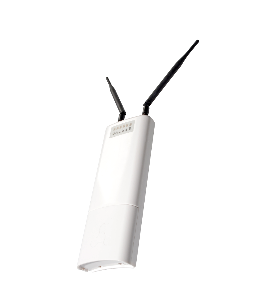
WOP-2ac-LR5 housed in a plastic case, industrial version. The size of the device: 80x232.5x47 mm. The appearance of WOP-2ac-LR5 is shown in the Fig. 2.

| Якорь | ||||
|---|---|---|---|---|
|
A combo port 10/100/1000Base-T (Ethernet)/100/1000Base-X (SFP) for local network connection and power supply via PoE, a grounding terminal (for WOP-2ac-LR5 H/W version 1v5 and higher; for WOP-2ac-LR5 rev.B) and a factory reset button (F) are located under the cover at the bottom of the device, Fig. 3.


| Якорь | ||||
|---|---|---|---|---|
|
| Scroll Pagebreak |
|---|
...
The appearance of WOP-2ac-LR5 indication panel is shown in the Fig. 4.
| Якорь | ||||
|---|---|---|---|---|
|

Fig. 4 – WOP-2ac-LR5 indication panel appearance
...
Attach the bracket to the device with the screws provided, as shown in the figure below.


Install the device on communications mast/pole with Ethernet port down as it is shown in the figure below. Attach the device using clamps supplied in the device package. Follow the safety rules and recommendations given in Safety rules and Installation recommendations.

- Remove the cover that closes the Ethernet port on the bottom panel of the device. Ground the device using a grounding connector (for H/W version: 1v5 and higher), then connect the Ethernet cable to the PoE port. When building a network over fiber, install the transceiver and make the connection.
- Close the bottom cover.
- Connect the antenna to the device using the cable assemblies.
- Adjust the position of the antenna so that subscriber devices fall into the coverage area of the installed antenna.
- Connect the Ethernet cable coming from WOP-2ac-LR5 to the PoE port or the injector or switch (IEEE 802.3at-2009).
- If you use a PoE injector, connect it to 220 V power supply network using the cable.
- Adjust the antenna more precisely using light indicators on the device.
...