...
The range of ONT NTU equipment produced by ELTEX comprises of terminals with two UNI interfaces of 10/100/1000Base-T and supports for FXS, USB1, RF2 interfaces:
- NTU-52V, NTU-52VC
...
NTU-52V/VC series devices are designed to support various interfaces and features, see Table 1.
| Якорь | ||||
|---|---|---|---|---|
|
...
- Ports to connect network devices (FXS):
- 1xPON SC/APC port for connection to provider's network (WAN);
- Ethernet RJ-45 LAN ports for connection of network devices (LAN):
- 1 port of RJ-45 10/100Base-T (for details see Section 3. Design);
- 1 port of RJ-45 10/100/1000Base-T (for details see Section 3. Design);
- 1 USB 2.0 port for external USB or HDD storages3278132772.
- 1 RF port for cable television (CaTV) connection3278132771.
...
1Only for NTU-52VC Якорь 1 1
...
- Network functions:
- bridge or router operation mode;
- PPPoE (auto, PAP, CHAP, MSCHAP authorization);
- IPoE (DHCP-client and static);
- static IP address and DHCP (DHCP client on WAN side, DHCP server on LAN side);
- DNS (Domain Name System);
- DynDNS (Dynamic DNS);
- UPnP (Universal Plug and Play);
- IPsec (IP Security);
- NAT (Network Address Translation);
- Firewall;
- NTP (Network Time Protocol);
- QoS;
- IGMP snooping;
- IGMP proxy;
- Parental Control;
- Storage service;
- SMB, FTP, Print Server;
- VLAN in accordance with IEEE 802.1Q.
- VoIP
- SIP
- audio codecs: G.729 (A), G.711(A/U), G.723.1;
- echo cancellation (G.164 and G.165 guidelines);
- Voice activity detection (VAD);
- Comfort noise generator (CNG);
- DTMF signal detection and generation
- DTMF transmission (INBAND, RFC2833, SIP INFO)
- Fax transmission: G.711, T.38
- Caller ID display.
- Firmware updates via web interface, TR-069, OMCI.
- Remote monitoring, configuration and setup:
- TR-069;
- Web interface;
- OMCI.
- CaTV1.
...
1Only for NTU-52VC Якорь onemoredesc onemoredesc
...
The rear panel layout of the devices is depicted in Fig. 2, 3.
| Якорь | ||||
|---|---|---|---|---|
|
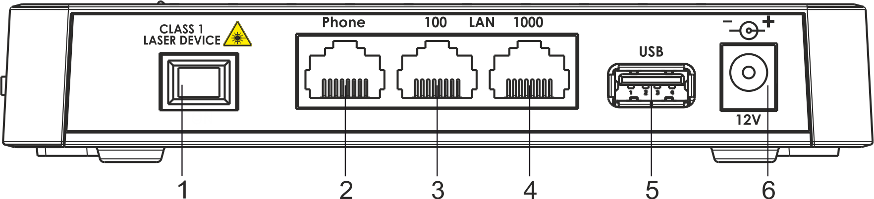
Figure 2 — NTU-52V rear panel layout
Connectors and controls located on the rear panel of 52V are listed in Table 3.
| Якорь | ||||
|---|---|---|---|---|
|
...
Connectors and controls located on the rear panel of 52VC are listed in Table 4.
| Scroll Pagebreak |
|---|
| Якорь | ||||
|---|---|---|---|---|
|
...
Figure 4 — NTU-52V side panel layout
See Table 5 for detailed information about buttons located on the side panel of the device.
...
The top panel layout of the NTU-52V is depicted in Fig. 5, the front panel layout is depicted in Fig. 6.
| Якорь | ||||
|---|---|---|---|---|
|
Figure 5 — NTU-52V top panel layout
...
The LED indicators located on the top and front panels show the current device status. Table 6 lists possible statuses of the LEDs.
| Scroll Pagebreak |
|---|
...
The front panel layout of the NTU-52VC is depicted in Figure 7.
| Якорь | ||||
|---|---|---|---|---|
|
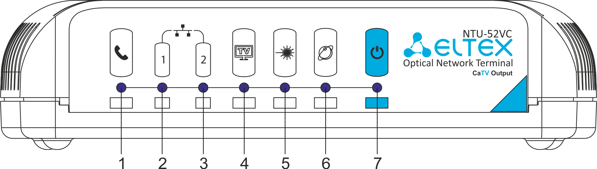
Figure 7 — NTU-52VC front panel layout
The LED indicators located on the front panel show the current state of the device. Table 7 provides possible statuses of the LEDs.
...
A device with factory (initial) settings have the following logical blocks (see Fig.8):
- Br0;
- Voice (VoIP block);
- eth0…1;
- FXS0;
- IPInterface1.
...
The tab displays the current status of PON interface system.
Status → PON

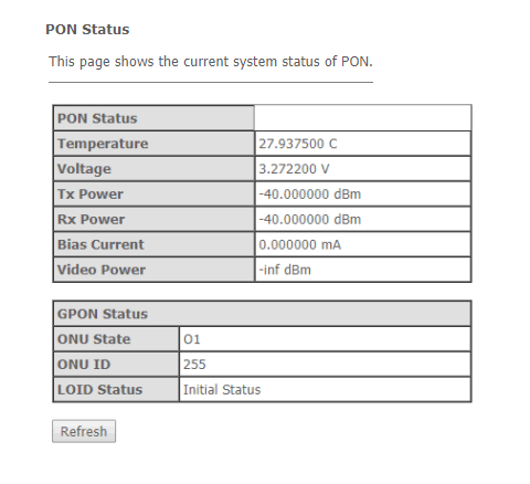
PON Status
- Vendor Name – manufacturer name;
- Part Number – part number;
- Temperature – current temperature;
- Voltage – voltage;
- Tx Power – transmission signal power;
- Rx Power – reception signal power;
- Bias Current – bias current;
- Video Power – video signal power.
...