| A Shared Block | |||||
|---|---|---|---|---|---|
| |||||
|
| Scroll Ignore | ||||
|---|---|---|---|---|
|
Introduction
This manual describes the main provisions and principles of forming acs profile on the example of GPON ELTEX NTU-RG1421G-Wac and NTU-2W subscriber terminals.
Creation of ACS profile for NTU-RG-1421G-Wac terminal
Default configuration description of the NTU-RG-1421G-Wac terminal
Before proceeding to acs profiling, let's look at the default configuration of ONT using the example of NTU-RG-1421G-Wac subscriber terminal. Each default configuration block will be discussed below.
The default configuration as acs parameters is as follows:
| Блок кода |
|---|
"InternetGatewayDevice.Layer2Bridging.Bridge.1.BridgeEnable" "TRUE" "InternetGatewayDevice.Layer2Bridging.Bridge.1.BridgeStandard" "802.1Q" "InternetGatewayDevice.Layer2Bridging.Bridge.1.VLANID" " " "InternetGatewayDevice.Layer2Bridging.Bridge.1.BridgeName" "DEFAULT" |
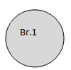
This parameter block generates the default LAN interface – Bridge 1.
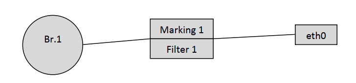
The eth0 interface is then binded to Br.1.
| Блок кода |
|---|
"InternetGatewayDevice.Layer2Bridging.Marking.1.MarkingEnable" "TRUE" "InternetGatewayDevice.Layer2Bridging.Marking.1.MarkingBridgeReference" "1" "InternetGatewayDevice.Layer2Bridging.Marking.1.MarkingInterface" "1" "InternetGatewayDevice.Layer2Bridging.Marking.1.EthernetPriorityMark" "3" "InternetGatewayDevice.Layer2Bridging.Marking.1.VLANIDUntag" "1" "InternetGatewayDevice.Layer2Bridging.Marking.1.VLANIDMark" "-1" "InternetGatewayDevice.Layer2Bridging.Marking.1.VLANIDMarkOverride" "0" "InternetGatewayDevice.Layer2Bridging.Filter.1.FilterEnable" "TRUE" "InternetGatewayDevice.Layer2Bridging.Filter.1.FilterBridgeReference" "1" "InternetGatewayDevice.Layer2Bridging.Filter.1.FilterInterface" "1" "InternetGatewayDevice.Layer2Bridging.Filter.1.VLANIDFilter" "-1" "InternetGatewayDevice.Layer2Bridging.Filter.1.AdmitOnlyVLANTagged" "0" |
At this stage, you should pay attention to the following parameters:
| Блок кода |
|---|
"InternetGatewayDevice.Layer2Bridging.Marking.1.MarkingBridgeReference" "1" "InternetGatewayDevice.Layer2Bridging.Marking.1.MarkingInterface" "1" "InternetGatewayDevice.Layer2Bridging.Filter.1.FilterBridgeReference" "1" "InternetGatewayDevice.Layer2Bridging.Filter.1.FilterInterface" "1" |
| Примечание |
|---|
The Filter and Marking parameters are responsible for binding the interface to the group (in this case eth0 to Br.1). The Filter parameter enables incoming traffic and Marking – outgoing traffic. |
"InternetGatewayDevice.Layer2Bridging.Marking.1.MarkingBridgeReference" "1" – creates Marking.1 – bind local eth0 interface to Bridge 1 for outgoing traffic. The number of the bridge to which the interface is bound is set by the "MarkingBridgeReference" parameter value. In this case the local interface is bound to Bridge 1.
"InternetGatewayDevice.Layer2Bridging.Marking.1.MarkingInterface" "1" – this parameter specifies the number of the local interface eth0, which is bound by the marking (Marking 1) to Bridge 1.
"InternetGatewayDevice.Layer2Bridging.Filter.1.FilterBridgeReference" "1" – this parameter generates bindings of the local interface to Bridge 1 for outgoing traffic.
"InternetGatewayDevice.Layer2Bridging.Filter.1.FilterInterface" "1" – this parameter is used to bind the local eth0 interface to Bridge 1.
After binding eth0 to Br.1 we get the following construction:
| Примечание |
|---|
The default numbering of interfaces, markings and filters must be followed to create a correctly working acs profile. Strict compliance between markings, filters and local interfaces must also be ensured. |
Numbering and matching of local interfaces to filters and markings are given in Tables 1.1 and 1.2.
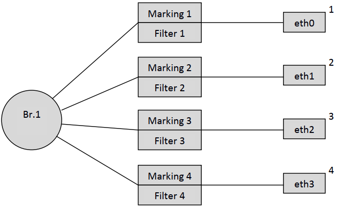
The following parameters bind local interfaces eth1, eth2 and eth3 to the Bridge by analogy with eth0.
| Блок кода |
|---|
"InternetGatewayDevice.Layer2Bridging.Marking.2.MarkingEnable" "TRUE" "InternetGatewayDevice.Layer2Bridging.Marking.2.MarkingBridgeReference" "1" "InternetGatewayDevice.Layer2Bridging.Marking.2.MarkingInterface" "2" "InternetGatewayDevice.Layer2Bridging.Marking.2.EthernetPriorityMark" "3" "InternetGatewayDevice.Layer2Bridging.Marking.2.VLANIDUntag" "1" "InternetGatewayDevice.Layer2Bridging.Marking.2.VLANIDMark" "-1" "InternetGatewayDevice.Layer2Bridging.Marking.2.VLANIDMarkOverride" "0" "InternetGatewayDevice.Layer2Bridging.Filter.2.FilterEnable" "TRUE" "InternetGatewayDevice.Layer2Bridging.Filter.2.FilterBridgeReference" "1" "InternetGatewayDevice.Layer2Bridging.Filter.2.FilterInterface" "2" "InternetGatewayDevice.Layer2Bridging.Filter.2.VLANIDFilter" "-1" "InternetGatewayDevice.Layer2Bridging.Filter.2.AdmitOnlyVLANTagged" "0" "InternetGatewayDevice.Layer2Bridging.Marking.3.MarkingEnable" "TRUE" "InternetGatewayDevice.Layer2Bridging.Marking.3.MarkingBridgeReference" "1" "InternetGatewayDevice.Layer2Bridging.Marking.3.MarkingInterface" "3" "InternetGatewayDevice.Layer2Bridging.Marking.3.EthernetPriorityMark" "3" "InternetGatewayDevice.Layer2Bridging.Marking.3.VLANIDUntag" "1" "InternetGatewayDevice.Layer2Bridging.Marking.3.VLANIDMark" "-1" "InternetGatewayDevice.Layer2Bridging.Marking.3.VLANIDMarkOverride" "0" "InternetGatewayDevice.Layer2Bridging.Filter.3.FilterEnable" "TRUE" "InternetGatewayDevice.Layer2Bridging.Filter.3.FilterBridgeReference" "1" "InternetGatewayDevice.Layer2Bridging.Filter.3.FilterInterface" "3" "InternetGatewayDevice.Layer2Bridging.Filter.3.VLANIDFilter" "-1" "InternetGatewayDevice.Layer2Bridging.Filter.3.AdmitOnlyVLANTagged" "0" "InternetGatewayDevice.Layer2Bridging.Marking.4.MarkingEnable" "TRUE" "InternetGatewayDevice.Layer2Bridging.Marking.4.MarkingBridgeReference" "1" "InternetGatewayDevice.Layer2Bridging.Marking.4.MarkingInterface" "4" "InternetGatewayDevice.Layer2Bridging.Marking.4.EthernetPriorityMark" "3" "InternetGatewayDevice.Layer2Bridging.Marking.4.VLANIDUntag" "1" "InternetGatewayDevice.Layer2Bridging.Marking.4.VLANIDMark" "-1" "InternetGatewayDevice.Layer2Bridging.Marking.4.VLANIDMarkOverride" "0" "InternetGatewayDevice.Layer2Bridging.Filter.4.FilterEnable" "TRUE" "InternetGatewayDevice.Layer2Bridging.Filter.4.FilterBridgeReference" "1" "InternetGatewayDevice.Layer2Bridging.Filter.4.FilterInterface" "4" "InternetGatewayDevice.Layer2Bridging.Filter.4.VLANIDFilter" "-1" "InternetGatewayDevice.Layer2Bridging.Filter.4.AdmitOnlyVLANTagged" "0" |
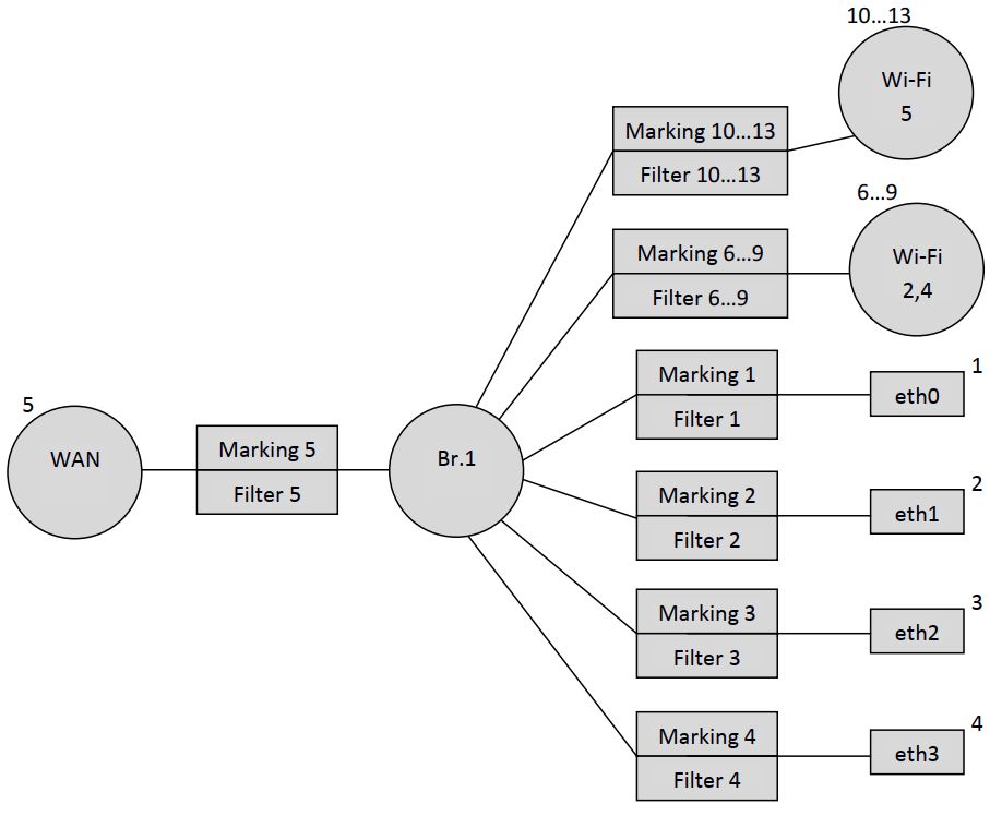
So, after binding the four interfaces to the first bridge, we have the following schematic design:
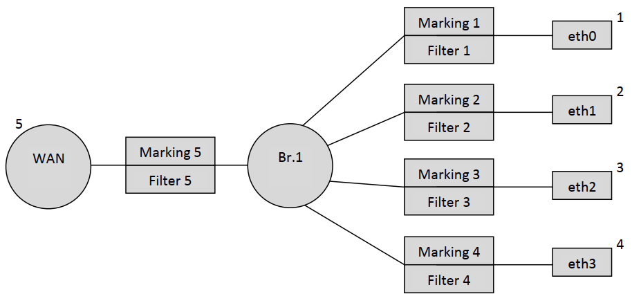
Then, according to the default interface numbering order (Table 1.1), the WAN virtual interface is bound to Bridge 1.
| Блок кода |
|---|
"InternetGatewayDevice.Layer2Bridging.Marking.5.MarkingEnable" "TRUE" "InternetGatewayDevice.Layer2Bridging.Marking.5.MarkingBridgeReference" "1" "InternetGatewayDevice.Layer2Bridging.Marking.5.MarkingInterface" "5" "InternetGatewayDevice.Layer2Bridging.Marking.5.EthernetPriorityMark" "3" "InternetGatewayDevice.Layer2Bridging.Marking.5.VLANIDUntag" "0" "InternetGatewayDevice.Layer2Bridging.Marking.5.VLANIDMark" " " "InternetGatewayDevice.Layer2Bridging.Marking.5.VLANIDMarkOverride" "1" "InternetGatewayDevice.Layer2Bridging.Filter.5.FilterEnable" "TRUE" "InternetGatewayDevice.Layer2Bridging.Filter.5.FilterBridgeReference" "1" "InternetGatewayDevice.Layer2Bridging.Filter.5.FilterInterface" "5" "InternetGatewayDevice.Layer2Bridging.Filter.5.VLANIDFilter" "-1" "InternetGatewayDevice.Layer2Bridging.Filter.5.AdmitOnlyVLANTagged" "0" |
As a result, our configuration looks like:
| Примечание |
|---|
Note that the local WAN IP interface number has the number 5 in the default interface numbering. |
Then, like eth0 – eth3, the interfaces wl0, wl0.1, wl0.2, wl0.3 (Wi-Fi 2.4 GHz) and wl1, wl1.1, wl1.2, and wl1.3 (Wi-Fi 5 GHz) are bound to Bridge 1.
| Блок кода |
|---|
"InternetGatewayDevice.Layer2Bridging.Marking.6.EthernetPriorityMark" "-1" "InternetGatewayDevice.Layer2Bridging.Marking.6.MarkingBridgeReference" "1" "InternetGatewayDevice.Layer2Bridging.Marking.6.MarkingEnable" "1" "InternetGatewayDevice.Layer2Bridging.Marking.6.MarkingInterface" "6" "InternetGatewayDevice.Layer2Bridging.Marking.6.VLANIDMark" "-1" "InternetGatewayDevice.Layer2Bridging.Marking.6.VLANIDMarkOverride" "0" "InternetGatewayDevice.Layer2Bridging.Marking.6.VLANIDUntag" "1" "InternetGatewayDevice.Layer2Bridging.Filter.6.AdmitOnlyVLANTagged" "0" "InternetGatewayDevice.Layer2Bridging.Filter.6.FilterBridgeReference" "1" "InternetGatewayDevice.Layer2Bridging.Filter.6.FilterEnable" "1" "InternetGatewayDevice.Layer2Bridging.Filter.6.FilterInterface" "6" "InternetGatewayDevice.Layer2Bridging.Filter.6.VLANIDFilter" "-1" "InternetGatewayDevice.Layer2Bridging.Marking.7.EthernetPriorityMark" "-1" "InternetGatewayDevice.Layer2Bridging.Marking.7.MarkingBridgeReference" "1" "InternetGatewayDevice.Layer2Bridging.Marking.7.MarkingEnable" "1" "InternetGatewayDevice.Layer2Bridging.Marking.7.MarkingInterface" "7" "InternetGatewayDevice.Layer2Bridging.Marking.7.VLANIDMark" "-1" "InternetGatewayDevice.Layer2Bridging.Marking.7.VLANIDMarkOverride" "0" "InternetGatewayDevice.Layer2Bridging.Marking.7.VLANIDUntag" "1" "InternetGatewayDevice.Layer2Bridging.Filter.7.AdmitOnlyVLANTagged" "0" "InternetGatewayDevice.Layer2Bridging.Filter.7.FilterBridgeReference" "1" "InternetGatewayDevice.Layer2Bridging.Filter.7.FilterEnable" "1" "InternetGatewayDevice.Layer2Bridging.Filter.7.FilterInterface" "7" "InternetGatewayDevice.Layer2Bridging.Filter.7.VLANIDFilter" "-1" "InternetGatewayDevice.Layer2Bridging.Marking.8.EthernetPriorityMark" "-1" "InternetGatewayDevice.Layer2Bridging.Marking.8.MarkingBridgeReference" "1" "InternetGatewayDevice.Layer2Bridging.Marking.8.MarkingEnable" "1" "InternetGatewayDevice.Layer2Bridging.Marking.8.MarkingInterface" "8" "InternetGatewayDevice.Layer2Bridging.Marking.8.VLANIDMark" "-1" "InternetGatewayDevice.Layer2Bridging.Marking.8.VLANIDMarkOverride" "0" "InternetGatewayDevice.Layer2Bridging.Marking.8.VLANIDUntag" "1" "InternetGatewayDevice.Layer2Bridging.Filter.8.AdmitOnlyVLANTagged" "0" "InternetGatewayDevice.Layer2Bridging.Filter.8.FilterBridgeReference" "1" "InternetGatewayDevice.Layer2Bridging.Filter.8.FilterEnable" "1" "InternetGatewayDevice.Layer2Bridging.Filter.8.FilterInterface" "8" "InternetGatewayDevice.Layer2Bridging.Filter.8.VLANIDFilter" "-1" "InternetGatewayDevice.Layer2Bridging.Marking.9.EthernetPriorityMark" "-1" "InternetGatewayDevice.Layer2Bridging.Marking.9.MarkingBridgeReference" "1" "InternetGatewayDevice.Layer2Bridging.Marking.9.MarkingEnable" "1" "InternetGatewayDevice.Layer2Bridging.Marking.9.MarkingInterface" "9" "InternetGatewayDevice.Layer2Bridging.Marking.9.VLANIDMark" "-1" "InternetGatewayDevice.Layer2Bridging.Marking.9.VLANIDMarkOverride" "0" "InternetGatewayDevice.Layer2Bridging.Marking.9.VLANIDUntag" "1" "InternetGatewayDevice.Layer2Bridging.Filter.9.AdmitOnlyVLANTagged" "0" "InternetGatewayDevice.Layer2Bridging.Filter.9.FilterBridgeReference" "1" "InternetGatewayDevice.Layer2Bridging.Filter.9.FilterEnable" "1" "InternetGatewayDevice.Layer2Bridging.Filter.9.FilterInterface" "9" "InternetGatewayDevice.Layer2Bridging.Filter.9.VLANIDFilter" "-1" "InternetGatewayDevice.Layer2Bridging.Marking.10.EthernetPriorityMark" "-1" "InternetGatewayDevice.Layer2Bridging.Marking.10.MarkingBridgeReference" "1" "InternetGatewayDevice.Layer2Bridging.Marking.10.MarkingEnable" "1" "InternetGatewayDevice.Layer2Bridging.Marking.10.MarkingInterface" "10" "InternetGatewayDevice.Layer2Bridging.Marking.10.VLANIDMark" "-1" "InternetGatewayDevice.Layer2Bridging.Marking.10.VLANIDMarkOverride" "0" "InternetGatewayDevice.Layer2Bridging.Marking.10.VLANIDUntag" "1" "InternetGatewayDevice.Layer2Bridging.Filter.10.AdmitOnlyVLANTagged" "0" "InternetGatewayDevice.Layer2Bridging.Filter.10.FilterBridgeReference" "1" "InternetGatewayDevice.Layer2Bridging.Filter.10.FilterEnable" "1" "InternetGatewayDevice.Layer2Bridging.Filter.10.FilterInterface" "10" "InternetGatewayDevice.Layer2Bridging.Filter.10.VLANIDFilter" "-1" "InternetGatewayDevice.Layer2Bridging.Marking.11.EthernetPriorityMark" "-1" "InternetGatewayDevice.Layer2Bridging.Marking.11.MarkingBridgeReference" "1" "InternetGatewayDevice.Layer2Bridging.Marking.11.MarkingEnable" "1" "InternetGatewayDevice.Layer2Bridging.Marking.11.MarkingInterface" "11" "InternetGatewayDevice.Layer2Bridging.Marking.11.VLANIDMark" "-1" "InternetGatewayDevice.Layer2Bridging.Marking.11.VLANIDMarkOverride" "0" "InternetGatewayDevice.Layer2Bridging.Marking.11.VLANIDUntag" "1" "InternetGatewayDevice.Layer2Bridging.Filter.11.AdmitOnlyVLANTagged" "0" "InternetGatewayDevice.Layer2Bridging.Filter.11.FilterBridgeReference" "1" "InternetGatewayDevice.Layer2Bridging.Filter.11.FilterEnable" "1" "InternetGatewayDevice.Layer2Bridging.Filter.11.FilterInterface" "11" "InternetGatewayDevice.Layer2Bridging.Filter.11.VLANIDFilter" "-1" "InternetGatewayDevice.Layer2Bridging.Marking.12.EthernetPriorityMark" "-1" "InternetGatewayDevice.Layer2Bridging.Marking.12.MarkingBridgeReference" "1" "InternetGatewayDevice.Layer2Bridging.Marking.12.MarkingEnable" "1" "InternetGatewayDevice.Layer2Bridging.Marking.12.MarkingInterface" "12" "InternetGatewayDevice.Layer2Bridging.Marking.12.VLANIDMark" "-1" "InternetGatewayDevice.Layer2Bridging.Marking.12.VLANIDMarkOverride" "0" "InternetGatewayDevice.Layer2Bridging.Marking.12.VLANIDUntag" "1" "InternetGatewayDevice.Layer2Bridging.Filter.12.AdmitOnlyVLANTagged" "0" "InternetGatewayDevice.Layer2Bridging.Filter.12.FilterBridgeReference" "1" "InternetGatewayDevice.Layer2Bridging.Filter.12.FilterEnable" "1" "InternetGatewayDevice.Layer2Bridging.Filter.12.FilterInterface" "12" "InternetGatewayDevice.Layer2Bridging.Filter.12.VLANIDFilter" "-1" "InternetGatewayDevice.Layer2Bridging.Marking.13.EthernetPriorityMark" "-1" "InternetGatewayDevice.Layer2Bridging.Marking.13.MarkingBridgeReference" "1" "InternetGatewayDevice.Layer2Bridging.Marking.13.MarkingEnable" "1" "InternetGatewayDevice.Layer2Bridging.Marking.13.MarkingInterface" "13" "InternetGatewayDevice.Layer2Bridging.Marking.13.VLANIDMark" "-1" "InternetGatewayDevice.Layer2Bridging.Marking.13.VLANIDMarkOverride" "0" "InternetGatewayDevice.Layer2Bridging.Marking.13.VLANIDUntag" "1" "InternetGatewayDevice.Layer2Bridging.Filter.13.AdmitOnlyVLANTagged" "0" "InternetGatewayDevice.Layer2Bridging.Filter.13.FilterBridgeReference" "1" "InternetGatewayDevice.Layer2Bridging.Filter.13.FilterEnable" "1" "InternetGatewayDevice.Layer2Bridging.Filter.13.FilterInterface" "13" "InternetGatewayDevice.Layer2Bridging.Filter.13.VLANIDFilter" "-1" |
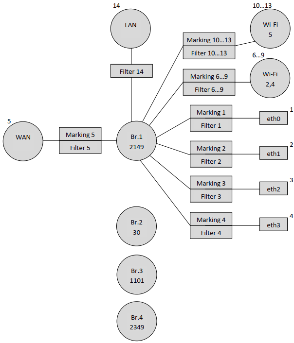
After adding the wl0 and wl1 interfaces, the configuration will look like this:
| Примечание |
|---|
Interfaces with 6.7, 8, 9 numbers correspond to Wi-Fi 2.4 GHz network interfaces. Accordingly, wl0 is the interface for the primary Wi-Fi network (6), and wl0.1 (7), wl0.2 (8), wl0.3 (9) are the interfaces for guest Wi-Fi networks. Similarly, the 10,11,12,13 interfaces correspond to the Wi-Fi interfaces of a 5 GHz network. |
Binding of the interface for local access to ONT (LAN IP) is done only by using a filter, without marking. And pay attention to the filter number for LAN IP 14, which is the next one after wl1.3.
| Блок кода |
|---|
"InternetGatewayDevice.Layer2Bridging.Filter.14.FilterEnable" "1" "InternetGatewayDevice.Layer2Bridging.Filter.14.FilterBridgeReference" "1" "InternetGatewayDevice.Layer2Bridging.Filter.14.FilterInterface" "14" "InternetGatewayDevice.Layer2Bridging.Filter.14.VLANIDFilter" "-1" "InternetGatewayDevice.Layer2Bridging.Filter.14.AdmitOnlyVLANTagged" "0" |
Interface number 14 is used for LAN IP.
The following parameters prescribe the LAN IP settings (these parameters are optional, i.e. they do not have to be used in the ACS profile):
| Блок кода |
|---|
"InternetGatewayDevice.LANDevice.1.LANHostConfigManagement.IPInterface.1.Enable" "1" "InternetGatewayDevice.LANDevice.1.LANHostConfigManagement.IPInterface.1.IPInterfaceAddressingType" "Static" "InternetGatewayDevice.LANDevice.1.LANHostConfigManagement.IPInterface.1.IPInterfaceIPAddress" "192.168.1.1" "InternetGatewayDevice.LANDevice.1.LANHostConfigManagement.IPInterface.1.IPInterfaceSubnetMask" "255.255.255.0" |
"InternetGatewayDevice.LANDevice.1.LANHostConfigManagement.IPInterface.1.Enable" "1" – enables IP interface LAN.
"InternetGatewayDevice.LANDevice.1.LANHostConfigManagement.IPInterface.1.IPInterfaceAddressingType" "Static" – specifying that the way the address is set on the interfacing is static.
"InternetGatewayDevice.LANDevice.1.LANHostConfigManagement.IPInterface.1.IPInterfaceIPAddress" "192.168.1.1" – specifies the default 192.168.1.1 address to access the LAN IP ONT from the local network.
"InternetGatewayDevice.LANDevice.1.LANHostConfigManagement.IPInterface.1.IPInterfaceSubnetMask" "255.255.255.0" – this parameter defines the subnetwork mask for LAN IP.
Thus, the default configuration has the following schematic view:

The following table listing the order numbers of the markers and filters and the default order numbers of the main ONT NTU-RG-1421G-Wac configuration interfaces.
Table 1.1. Basic interface numbering and sequential numbers of markers and filters in default configuration for NTU-RG-1421G-Wac
Interface | Marking | Filter | Marking Interface | Filter Interface | Bridge |
|---|---|---|---|---|---|
Eth0 | 1 | 1 | 1 | 1 | 1 |
Eth1 | 2 | 2 | 2 | 2 | 1 |
Eth2 | 3 | 3 | 3 | 3 | 1 |
Eth3 | 4 | 4 | 4 | 4 | 1 |
WAN | 5 | 5 | 5 | 5 | 1 |
Wl0 | 6 | 6 | 6 | 6 | 1 |
Wl0.1 | 7 | 7 | 7 | 7 | 1 |
Wl0.2 | 8 | 8 | 8 | 8 | 1 |
Wl0.3 | 9 | 9 | 9 | 9 | 1 |
Wl1 | 10 | 10 | 10 | 10 | 1 |
Wl1.1 | 11 | 11 | 11 | 11 | 1 |
Wl1.2 | 12 | 12 | 12 | 12 | 1 |
Wl1.3 | 13 | 13 | 13 | 13 | 1 |
LAN IP | - | 14 | - | 14 | 1 |
Forming a profile for a specific configuration of the NTU-RG-1421G-Wac terminal
Let's consider the process of profiling acs for an abstract subscriber terminal where it is required to raise the PPPoE-client and transfer traffic from it to the subscriber equipment located behind NAT ONT on 0.1 and 2 ports in vlan 2149. It is necessary that the IGMP Proxy ONT work in 30 vlan. It is also necessary to organize the obtaining of IP-address on IP-TV media player (STB) on port 3 ONT in vlan 2349 and IP-telephony in vlan 1101.
We will create this profile based on the ONT default configuration discussed earlier.
It should be noted that there was only one Bridge in the default configuration. When profiling the acs, you should be guided by the fact that for each service (service) you need to create a separate bridge.
As described earlier, Bridge 1 is already present in the default configuration, we will use it for the Internet service. To do this, you need to specify in which VLAN the service will work and change the name of this bridge:
| Блок кода |
|---|
"InternetGatewayDevice.Layer2Bridging.Bridge.1.BridgeEnable" "TRUE" "InternetGatewayDevice.Layer2Bridging.Bridge.1.BridgeStandard" "802.1Q" "InternetGatewayDevice.Layer2Bridging.Bridge.1.VLANID" "2149" "InternetGatewayDevice.Layer2Bridging.Bridge.1.BridgeName" "Internet" |
Similar to Bridge 1, we'll create bridges for other services. Bridge for IGMP Proxy interface, in the same VLAN in our scheme goes multicast towards OLT:
| Блок кода |
|---|
"InternetGatewayDevice.Layer2Bridging.Bridge.2.BridgeStandard" "802.1Q" "InternetGatewayDevice.Layer2Bridging.Bridge.2.BridgeName" "IPTV" "InternetGatewayDevice.Layer2Bridging.Bridge.2.BridgeEnable" "1" "InternetGatewayDevice.Layer2Bridging.Bridge.2.VLANID" "30" |
Bridge for telephony service:
| Блок кода |
|---|
"InternetGatewayDevice.Layer2Bridging.Bridge.3.BridgeStandard" "802.1Q" "InternetGatewayDevice.Layer2Bridging.Bridge.3.BridgeName" "VoIP" "InternetGatewayDevice.Layer2Bridging.Bridge.3.BridgeEnable" "1" "InternetGatewayDevice.Layer2Bridging.Bridge.3.VLANID" "1101" |
Bridge for IPTV-STB:
| Блок кода |
|---|
"InternetGatewayDevice.Layer2Bridging.Bridge.4.BridgeStandard" "802.1Q" "InternetGatewayDevice.Layer2Bridging.Bridge.4.BridgeName" "Bridge" "InternetGatewayDevice.Layer2Bridging.Bridge.4.BridgeEnable" "1" "InternetGatewayDevice.Layer2Bridging.Bridge.4.VLANID" "2349" |
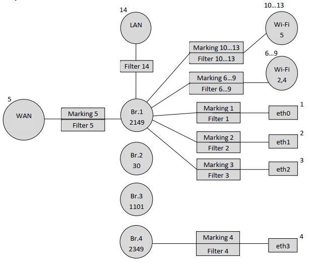
As a result, the scheme looks like this:
Since it is necessary to configure the receiving of IP address for STB in vlan 2349 behind the ONT eth3 port, it is necessary to bind the bridge of this service (Bridge 4) to the eth3 interface.
Marking 4 and Filter 4 are used to bind eth3 to a bridge, and the eth3 interface number in the ACS interpretation is 4:
| Блок кода |
|---|
"InternetGatewayDevice.Layer2Bridging.Marking.4.MarkingEnable" "TRUE" "InternetGatewayDevice.Layer2Bridging.Marking.4.MarkingBridgeReference" "4" "InternetGatewayDevice.Layer2Bridging.Marking.4.MarkingInterface" "4" "InternetGatewayDevice.Layer2Bridging.Marking.4.EthernetPriorityMark" "3" "InternetGatewayDevice.Layer2Bridging.Marking.4.VLANIDUntag" "1" "InternetGatewayDevice.Layer2Bridging.Marking.4.VLANIDMark" "-1" "InternetGatewayDevice.Layer2Bridging.Marking.4.VLANIDMarkOverride" "0" "InternetGatewayDevice.Layer2Bridging.Filter.4.FilterEnable" "TRUE" "InternetGatewayDevice.Layer2Bridging.Filter.4.FilterBridgeReference" "4" "InternetGatewayDevice.Layer2Bridging.Filter.4.FilterInterface" "4" "InternetGatewayDevice.Layer2Bridging.Filter.4.VLANIDFilter" "-1" "InternetGatewayDevice.Layer2Bridging.Filter.4.AdmitOnlyVLANTagged" "0" |
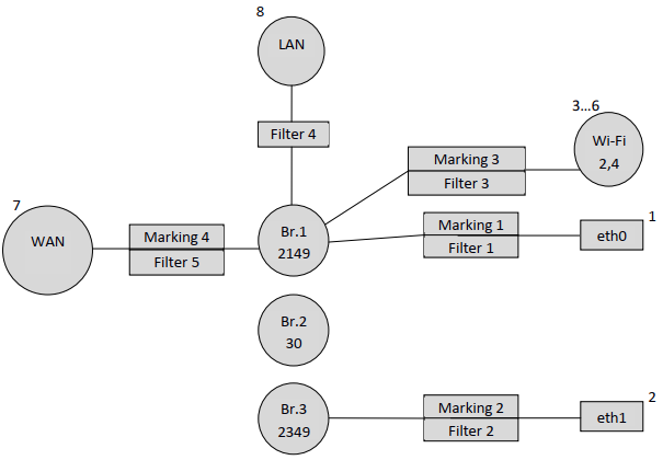
Replacing the number of the bridge to which eth3 will be bound from 1 to 4, we get a diagram:
Next you need to bind the WAN-interface to Bridge1. The WAN interface in the acs interpretation has the number 5 (see Table 1.1).
| Блок кода |
|---|
"InternetGatewayDevice.Layer2Bridging.Marking.5.MarkingEnable" "TRUE" "InternetGatewayDevice.Layer2Bridging.Marking.5.MarkingBridgeReference" "1" "InternetGatewayDevice.Layer2Bridging.Marking.5.MarkingInterface" "5" "InternetGatewayDevice.Layer2Bridging.Marking.5.EthernetPriorityMark" "3" "InternetGatewayDevice.Layer2Bridging.Marking.5.VLANIDUntag" "0" "InternetGatewayDevice.Layer2Bridging.Marking.5.VLANIDMarkOverride" "1" |
"InternetGatewayDevice.Layer2Bridging.Marking.5.VLANIDMark" "2149" – pay attention to this parameter. When binding a WAN to a Bridge in Marking, the VLANIDMark parameter value must correspond to the vlan number of the Bridge to which the WAN is bound. In our case, vlan 2149 is used for Bridge 1, so the VLANIDMark value is "2149".
| Блок кода |
|---|
"InternetGatewayDevice.Layer2Bridging.Filter.5.FilterEnable" "TRUE" "InternetGatewayDevice.Layer2Bridging.Filter.5.FilterBridgeReference" "1" "InternetGatewayDevice.Layer2Bridging.Filter.5.FilterInterface" "5" "InternetGatewayDevice.Layer2Bridging.Filter.5.VLANIDFilter" "-1" "InternetGatewayDevice.Layer2Bridging.Filter.5.AdmitOnlyVLANTagged" "0" |
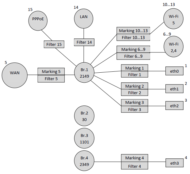
Now it is necessary to bind to Bridge 1 the interface of PPP, to be able to raise the PPPoE session between the ONT and the ISP equipment in vlan 2149.
There is also a special feature: to bind non-default service interfaces (LAN interface exception) to breeches, only filters should be used.
FilterInterface values for non-default interfaces must be consecutive and start after the highest FilterInterface value in the default configuration. In our case, the highest FilterInterface (interface number) value in the default configuration is 14 (LAN interface). Consequently, the FilterInterface for the first non-default interface will be 15.
The following lines bind PPP to Bridge 1.
| Блок кода |
|---|
"InternetGatewayDevice.Layer2Bridging.Filter.15.FilterEnable" "TRUE" "InternetGatewayDevice.Layer2Bridging.Filter.15.FilterBridgeReference" "1" "InternetGatewayDevice.Layer2Bridging.Filter.15.FilterInterface" "15" "InternetGatewayDevice.Layer2Bridging.Filter.15.VLANIDFilter" "-1" "InternetGatewayDevice.Layer2Bridging.Filter.15.AdmitOnlyVLANTagged" "0" |
The following parameters define the settings for the PPP interface.
"InternetGatewayDevice.WANDevice.1.WANConnectionDevice.1.WANPPPConnection.1.ConnectionType" "IP_Routed" – this parameter specifies interface type. The "IP_Routed" value specifies the router interface.
"InternetGatewayDevice.WANDevice.1.WANConnectionDevice.1.WANPPPConnection.1.Enable" "1" – this parameter enables WANPPP-interface. Value "1" – enable, "0" – disable
"InternetGatewayDevice.WANDevice.1.WANConnectionDevice.1.WANPPPConnection.1.Name” "PPPoE" – this parameter specifies the name "PPPoE" for the PPP interface. The name value can be any
"InternetGatewayDevice.WANDevice.1.WANConnectionDevice.1.WANPPPConnection.1.NATEnabled" "1" – enabling NAT on the PPP interface for translation of addresses from the local network. "1" - NAT enabled, "0" - NAT disabled.
"InternetGatewayDevice.WANDevice.1.WANConnectionDevice.1.WANPPPConnection.1.X_BROADCOM_COM_FirewallEnabled" "TRUE" – enabling the Firewall on the PPP interface. Value “1” – Firewall enabled, “0” – disabled.
"InternetGatewayDevice.WANDevice.1.WANConnectionDevice.1.WANPPPConnection.1.X_RTK_ServiceType" "1" – the type of service for which this interface will be used. The following types of services can be used: 1 – Internet, 4 – telephony, 5 – the interface will be used for both Internet and telephony services.
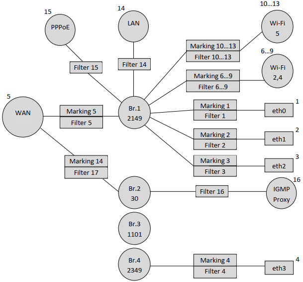
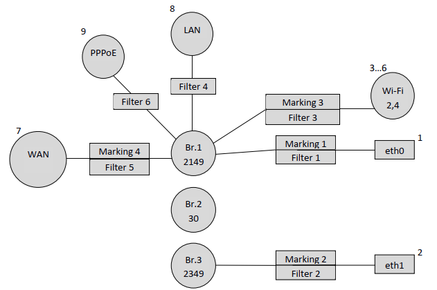
After applying all the above parameters, we get this logical ONT configuration:
Similarly, we create an IGMP-Proxy interface and bind it to Bridge 2, taking into account that non-default interfaces are bound only by filters.
| Блок кода |
|---|
"InternetGatewayDevice.Layer2Bridging.Filter.16.FilterEnable" "TRUE" "InternetGatewayDevice.Layer2Bridging.Filter.16.FilterBridgeReference" "2" "InternetGatewayDevice.Layer2Bridging.Filter.16.FilterInterface" "16" "InternetGatewayDevice.Layer2Bridging.Filter.16.VLANIDFilter" "-1" "InternetGatewayDevice.Layer2Bridging.Filter.16.AdmitOnlyVLANTagged" "0" |
The FilterInterface value for IGMP Proxy is 16 because the previous PPP interface had a value of 15.
Configure the IGMP Proxy interface with the following ACS parameters:
"InternetGatewayDevice.WANDevice.1.WANConnectionDevice.1.WANIPConnection.1.Enable" "1" – enable WANIP interface
"InternetGatewayDevice.WANDevice.1.WANConnectionDevice.1.WANIPConnection.1.AddressingType""Static" – this parameter specifies that the address for IGMP Proxy is set statically.
"InternetGatewayDevice.WANDevice.1.WANConnectionDevice.1.WANIPConnection.1.ConnectionType""IP_Routed" – this parameter specifies router interface type.
"InternetGatewayDevice.WANDevice.1.WANConnectionDevice.1.WANIPConnection.1.ExternalIPAddress" "192.168.21.21" – this parameter sets a static IP address for IGMP-Proxy
"InternetGatewayDevice.WANDevice.1.WANConnectionDevice.1.WANIPConnection.1.DefaultGateway" "192.168.21.1" – parameter specifies the default gateway
"InternetGatewayDevice.WANDevice.1.WANConnectionDevice.1.WANIPConnection.1.SubnetMask" "255.255.255.0" – sets the subnet mask for IGMP Proxy
"InternetGatewayDevice.WANDevice.1.WANConnectionDevice.1.WANIPConnection.1.Name" "IGMP" – this parameter sets a name for the IGMP Proxy. The value of "IGMP" name can be any.
"InternetGatewayDevice.WANDevice.1.WANConnectionDevice.1.WANIPConnection.1.X_BROADCOM_COM_IGMPEnabled" "TRUE" – this parameter enables the IGMP snooping function.
The static address 192.168.21.21 for IGMP is given as an example. When writing a profile, you can replace this address with any other address.
Next, you need to bind Bridge 2 to the WAN interface:
| Блок кода |
|---|
"InternetGatewayDevice.Layer2Bridging.Marking.14.MarkingEnable" "TRUE" "InternetGatewayDevice.Layer2Bridging.Marking.14.MarkingBridgeReference" "2" "InternetGatewayDevice.Layer2Bridging.Marking.14.MarkingInterface" "5" "InternetGatewayDevice.Layer2Bridging.Marking.14.EthernetPriorityMark" "3" "InternetGatewayDevice.Layer2Bridging.Marking.14.VLANIDUntag" "0" "InternetGatewayDevice.Layer2Bridging.Marking.14.VLANIDMark" "30" "InternetGatewayDevice.Layer2Bridging.Marking.14.VLANIDMarkOverride" "1" "InternetGatewayDevice.Layer2Bridging.Filter.17.FilterEnable" "TRUE" "InternetGatewayDevice.Layer2Bridging.Filter.17.FilterBridgeReference" "2" "InternetGatewayDevice.Layer2Bridging.Filter.17.FilterInterface" "5" "InternetGatewayDevice.Layer2Bridging.Filter.17.VLANIDFilter" "-1" "InternetGatewayDevice.Layer2Bridging.Filter.17.AdmitOnlyVLANTagged" "0" |
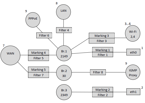
After adding Bridge 2 and IGMP Proxy, the ONT configuration will look like this:
The following parameters bind VoIP interface to Bridge 3:
| Блок кода |
|---|
set property "InternetGatewayDevice.Layer2Bridging.Filter.18.FilterEnable" "TRUE" nocheck set property "InternetGatewayDevice.Layer2Bridging.Filter.18.FilterBridgeReference" "3" nocheck set property "InternetGatewayDevice.Layer2Bridging.Filter.18.FilterInterface" "17" nocheck set property "InternetGatewayDevice.Layer2Bridging.Filter.18.VLANIDFilter" "-1" nocheck set property "InternetGatewayDevice.Layer2Bridging.Filter.18.AdmitOnlyVLANTagged" "0" nocheck |
"InternetGatewayDevice.WANDevice.1.WANConnectionDevice.1.WANIPConnection.2.Enable" "1"
"InternetGatewayDevice.WANDevice.1.WANConnectionDevice.1.WANIPConnection.2.AddressingType" "DHCP" – this parameter activates the address obtaining for the WAN interface for VoIP via DHCP.
"InternetGatewayDevice.WANDevice.1.WANConnectionDevice.1.WANIPConnection.2.ConnectionType" "IP_Routed"
"InternetGatewayDevice.WANDevice.1.WANConnectionDevice.1.WANIPConnection.2.Name" "VoIP"
"InternetGatewayDevice.WANDevice.1.WANConnectionDevice.1.WANPPPConnection.1.X_RTK_ServiceType" "4" – the type of service for which this interface will be used. For telephony service you need to specify 4.
Note index 2 of the WANIPConnection.2 parameter. In this case index 2 is used, because in the configuration it is already the second WANIP interface, the first was the IGMP Proxy interface.
Bind the WAN interface to Bridge 3:
| Блок кода |
|---|
"InternetGatewayDevice.Layer2Bridging.Marking.15.MarkingEnable" "TRUE" "InternetGatewayDevice.Layer2Bridging.Marking.15.MarkingBridgeReference" "3" "InternetGatewayDevice.Layer2Bridging.Marking.15.MarkingInterface" "5" "InternetGatewayDevice.Layer2Bridging.Marking.15.EthernetPriorityMark" "3" "InternetGatewayDevice.Layer2Bridging.Marking.15.VLANIDUntag" "0" "InternetGatewayDevice.Layer2Bridging.Marking.15.VLANIDMark" "1101" "InternetGatewayDevice.Layer2Bridging.Marking.15.VLANIDMarkOverride" "1" set property "InternetGatewayDevice.Layer2Bridging.Filter.19.FilterEnable" "TRUE" nocheck set property "InternetGatewayDevice.Layer2Bridging.Filter.19.FilterBridgeReference" "3" nocheck set property "InternetGatewayDevice.Layer2Bridging.Filter.19.FilterInterface" "5" nocheck set property "InternetGatewayDevice.Layer2Bridging.Filter.19.VLANIDFilter" "-1" nocheck set property "InternetGatewayDevice.Layer2Bridging.Filter.19.AdmitOnlyVLANTagged" "0" nocheck |
And the following acs parameters set the settings for VoIP - ONT client:
"InternetGatewayDevice.Services.VoiceService.1.VoiceProfile.1.SIP.UserAgentDomain" " ngn-sip.sinor.ru" – setting this parameter is mandatory, without it VoIP client does not work, the value of this parameter must be the same as ProxyServer or RegistarServer.
"InternetGatewayDevice.Services.VoiceService.1.VoiceProfile.1.SIP.ProxyServer" " ngn-sip.sinor.ru" – this parameter sets the registration servers. Either an IP address or a domain name can be used as the value.
"InternetGatewayDevice.Services.VoiceService.1.VoiceProfile.1.SIP.UserAgentPort" "5060" – this parameter defines the port in which the VoIP client ONT is running, the value 5060 is standard.
"InternetGatewayDevice.Services.VoiceService.1.VoiceProfile.1.SIP.RegistrarServer" "ngn-sip.sinor.ru " – parameter to set the registration server. Either an IP address or a domain name can be used as the value.
"InternetGatewayDevice.Services.VoiceService.1.VoiceProfile.1.SIP.RegistrarServerPort" "5060" – specifying the port where the SIP server is running, the value 5060 is standard.
"InternetGatewayDevice.Services.VoiceService.1.VoiceProfile.1.SIP.OutboundProxy" "ngn-sip.sinor.ru " – this parameter sets the OutboundProxy address. Either an IP address or a domain name can be used as the value.
"InternetGatewayDevice.Services.VoiceService.1.VoiceProfile.1.SIP.OutboundProxyPort" "5060" – this parameter defines the port for Outbound Proxy, 5060 – default value.
"InternetGatewayDevice.Services.VoiceService.1.VoiceProfile.1.SIP.RegisterExpires" "610" – this parameter specifies the time during which the SIP client registration on the server expires.
"InternetGatewayDevice.Services.VoiceService.1.VoiceProfile.1.SIP.RegistrationPeriod" "600" – acs parameter that specifies the period of time after which VoIP client will send a request for re-registration.
"InternetGatewayDevice.Services.VoiceService.1.VoiceProfile.1.Line.1.Enable" "Enabled" – enable first phone line.
"InternetGatewayDevice.Services.VoiceService.1.VoiceProfile.1.Line.1.SIP.AuthUserName" " 12345678" – acs parameter that specifies sip client name.
"InternetGatewayDevice.Services.VoiceService.1.VoiceProfile.1.Line.1.SIP.AuthPassword" "12345678" – acs parameter that specifies sip client password.
"InternetGatewayDevice.Services.VoiceService.1.VoiceProfile.1.Line.1.DirectoryNumber" "12345678" – this parameter specifies sip client phone number.
"InternetGatewayDevice.Services.VoiceService.1.VoiceProfile.1.Line.1.CallingFeatures.CallerIDName" "12345678" – this parameter specifies CallerID of the client.
"InternetGatewayDevice.Services.VoiceService.1.VoiceProfile.1.Line.1.SIP.URI" "12345678" – SIP URI of the sip client. By default, it should be the same as DirectoryNumber.
"InternetGatewayDevice.Services.VoiceService.1.VoiceProfile.1.Line.1.PhyReferenceList" "1" – this acs parameter specifies the physical FXS port behind which the client equipment is located. For Line 1 – the value of this parameter should be "1".
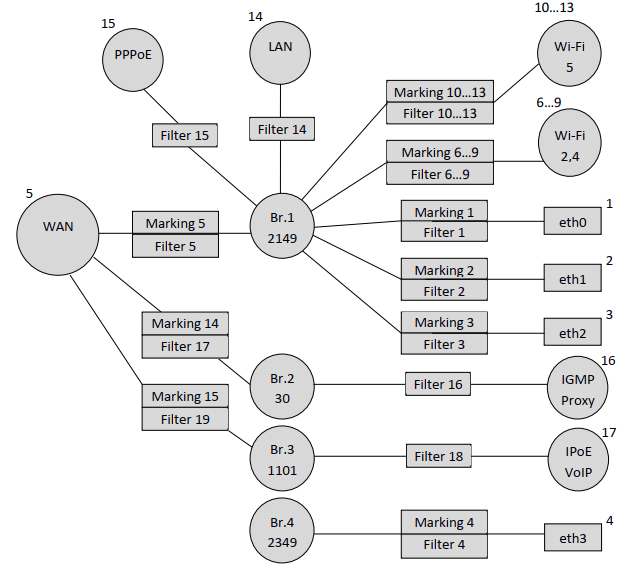
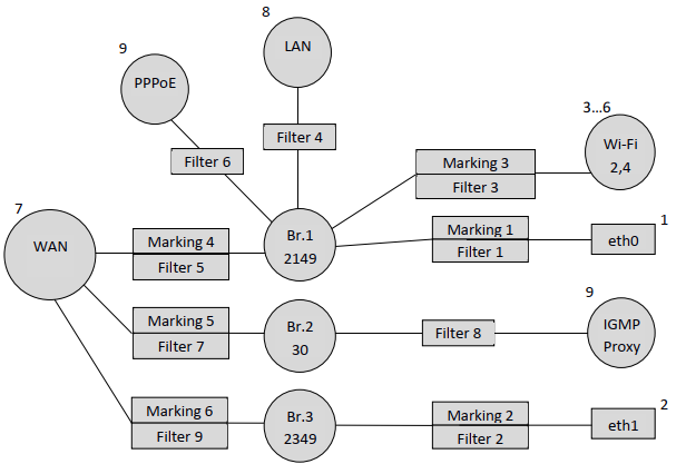
As a result, the scheme will look like:
The only thing left is to bind Bridge 4 to the WAN interface using parameters:
| Блок кода |
|---|
"InternetGatewayDevice.Layer2Bridging.Marking.16.MarkingEnable" "TRUE" "InternetGatewayDevice.Layer2Bridging.Marking.16.MarkingBridgeReference" "4" "InternetGatewayDevice.Layer2Bridging.Marking.16.MarkingInterface" "5" "InternetGatewayDevice.Layer2Bridging.Marking.16.EthernetPriorityMark" "3" "InternetGatewayDevice.Layer2Bridging.Marking.16.VLANIDUntag" "0" "InternetGatewayDevice.Layer2Bridging.Marking.16.VLANIDMark" "2349" "InternetGatewayDevice.Layer2Bridging.Marking.16.VLANIDMarkOverride" "1" "InternetGatewayDevice.Layer2Bridging.Filter.20.FilterEnable" "TRUE" "InternetGatewayDevice.Layer2Bridging.Filter.20.FilterBridgeReference" "3" "InternetGatewayDevice.Layer2Bridging.Filter.20.FilterInterface" "5" "InternetGatewayDevice.Layer2Bridging.Filter.20.VLANIDFilter" "-1" "InternetGatewayDevice.Layer2Bridging.Filter.20.AdmitOnlyVLANTagged" "0" |
Since the traffic through Bridge 4 will pass transparently, only with vlan 2349 unchecked, no additional ACS parameters other than Marking and Filter are required. That is, if it is necessary to provide a subscriber with some service by a bridge, it is enough to make a binding of a necessary port to bridge and binding of WAN interface to this bridge.
| Примечание |
|---|
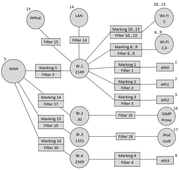
In the diagram below you can see that when binding some interfaces the numbers of Filter and Marking do not match, for example when binding bridges 2, 3 and 4 to the WAN interface. This is not an error, the filter and marking numbers may not match, the main thing when creating a profile is to observe their general numbering. |
Finally, on an ONT that is fully configured for this profile, the following logical architecture will be used:
Creation of ACS profile for NTU-2W terminal
Default configuration description of the NTU-2W terminal
Let's consider the process of making an ACS profile on the example of another device – NTU-2W. The following table listing the order numbers of the markers and filters and the default order numbers of the main configuration interfaces.
Table 1.2. Basic interface numbering and sequential numbers of markers and filters in default configuration
Interface | Marking | Filter | Marking Interface | Filter Interface | Bridge |
|---|---|---|---|---|---|
Eth0 | 1 | 1 | 1 | 1 | 1 |
Eth1 | 2 | 2 | 2 | 2 | 1 |
WLAN (Wl0) | 3 | 3 | 3 | 3 | 1 |
Wl0.1 | - | - | - | 4 | 1 |
Wl0.2 | - | - | - | 5 | 1 |
Wl0.3 | - | - | - | 6 | 1 |
WAN | 7 | 8 | 7 | 7 | 1 |
LAN IP | - | 7 | - | 8 | 1 |
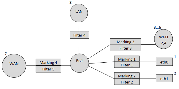
Based on the table above, we will make a schematic representation of the default configuration:
Forming a profile for a specific configuration of the NTU-RG-1421G-Wac terminal
Let's create a profile for the following configuration: you need to raise the PPPoE client and transfer traffic from it to the subscriber equipment located behind NAT ONT on port 0 in vlan 2149. It is necessary that the IGMP Proxy ONT work in 30 vlan. It is also necessary to arrange the obtaining of IP address on an IP-TV media player (STB) on port 1 of ONT in vlan 2349.
As in the previous example, let's start by adding service bridges:
| Блок кода |
|---|
"InternetGatewayDevice.Layer2Bridging.Bridge.1.BridgeEnable" "TRUE" "InternetGatewayDevice.Layer2Bridging.Bridge.1.BridgeStandard" "802.1Q" "InternetGatewayDevice.Layer2Bridging.Bridge.1.VLANID" "2149" "InternetGatewayDevice.Layer2Bridging.Bridge.1.BridgeName" "Internet" |
Bridge for IGMP Proxy interface:
| Блок кода |
|---|
"InternetGatewayDevice.Layer2Bridging.Bridge.2.BridgeStandard" "802.1Q" "InternetGatewayDevice.Layer2Bridging.Bridge.2.BridgeName" "IPTV" "InternetGatewayDevice.Layer2Bridging.Bridge.2.BridgeEnable" "1" "InternetGatewayDevice.Layer2Bridging.Bridge.2.VLANID" "30" |
Bridge for IPTV-STB:
| Блок кода |
|---|
"InternetGatewayDevice.Layer2Bridging.Bridge.3.BridgeStandard" "802.1Q" "InternetGatewayDevice.Layer2Bridging.Bridge.3.BridgeName" "Bridge" "InternetGatewayDevice.Layer2Bridging.Bridge.3.BridgeEnable" "1" "InternetGatewayDevice.Layer2Bridging.Bridge.3.VLANID" "2349" |
Next, bind the eth1 interface to Bridge 3:
| Блок кода |
|---|
"InternetGatewayDevice.Layer2Bridging.Marking.2.MarkingEnable" "TRUE" "InternetGatewayDevice.Layer2Bridging.Marking.2.MarkingBridgeReference" "3" "InternetGatewayDevice.Layer2Bridging.Marking.2.MarkingInterface" "4" "InternetGatewayDevice.Layer2Bridging.Marking.2.EthernetPriorityMark" "3" "InternetGatewayDevice.Layer2Bridging.Marking.2.VLANIDUntag" "0" "InternetGatewayDevice.Layer2Bridging.Marking.2.VLANIDMark" "-1" "InternetGatewayDevice.Layer2Bridging.Marking.2.VLANIDMarkOverride" "1" "InternetGatewayDevice.Layer2Bridging.Filter.2.FilterEnable" "TRUE" "InternetGatewayDevice.Layer2Bridging.Filter.2.FilterBridgeReference" "3" "InternetGatewayDevice.Layer2Bridging.Filter.2.FilterInterface" "4" "InternetGatewayDevice.Layer2Bridging.Filter.2.VLANIDFilter" "-1" "InternetGatewayDevice.Layer2Bridging.Filter.2.AdmitOnlyVLANTagged" "0" |
The result is a diagram:
FilterInterface values for interfaces other than the default should be consecutive and start after the highest FilterInterface value in the default configuration. In our case, the highest FilterInterface (interface number) value in the default configuration is 8 (LAN interface). Therefore, FilterInterface for the non-default first interface will be 9.
The following lines bind PPP to Bridge 1.
| Блок кода |
|---|
"InternetGatewayDevice.Layer2Bridging.Filter.6.FilterEnable" "TRUE" "InternetGatewayDevice.Layer2Bridging.Filter.6.FilterBridgeReference" "1" "InternetGatewayDevice.Layer2Bridging.Filter.6.FilterInterface" "9" "InternetGatewayDevice.Layer2Bridging.Filter.6.VLANIDFilter" "-1" "InternetGatewayDevice.Layer2Bridging.Filter.6.AdmitOnlyVLANTagged" "0" |
The following parameters define the settings for the PPP interface.
| Блок кода |
|---|
"InternetGatewayDevice.WANDevice.1.WANConnectionDevice.1.WANPPPConnection.1.ConnectionType" "IP_Routed" "InternetGatewayDevice.WANDevice.1.WANConnectionDevice.1.WANPPPConnection.1.Enable" "1" "InternetGatewayDevice.WANDevice.1.WANConnectionDevice.1.WANPPPConnection.1.Name” "PPPoE" "InternetGatewayDevice.WANDevice.1.WANConnectionDevice.1.WANPPPConnection.1.NATEnabled" "1" "InternetGatewayDevice.WANDevice.1.WANConnectionDevice.1.WANPPPConnection.1.X_BROADCOM_COM_FirewallEnabled" "TRUE" |
| Примечание |
|---|
The RTK_ServiceType parameter is not required here, it is only required for NTU-RG-1421G-Wac models. |
After adding the PPPoE interface, the diagram takes the form:
Next, you need to bind Bridge 2 to the WAN interface:
| Блок кода |
|---|
"InternetGatewayDevice.Layer2Bridging.Marking.5.MarkingEnable" "TRUE" "InternetGatewayDevice.Layer2Bridging.Marking.5.MarkingBridgeReference" "2" "InternetGatewayDevice.Layer2Bridging.Marking.5.MarkingInterface" "7" "InternetGatewayDevice.Layer2Bridging.Marking.5.EthernetPriorityMark" "3" "InternetGatewayDevice.Layer2Bridging.Marking.5.VLANIDUntag" "0" "InternetGatewayDevice.Layer2Bridging.Marking.5.VLANIDMark" "30" "InternetGatewayDevice.Layer2Bridging.Marking.5.VLANIDMarkOverride" "1" "InternetGatewayDevice.Layer2Bridging.Filter.7.FilterEnable" "TRUE" "InternetGatewayDevice.Layer2Bridging.Filter.7.FilterBridgeReference" "2" "InternetGatewayDevice.Layer2Bridging.Filter.7.FilterInterface" "7" "InternetGatewayDevice.Layer2Bridging.Filter.7.VLANIDFilter" "-1" "InternetGatewayDevice.Layer2Bridging.Filter.7.AdmitOnlyVLANTagged" "0" |
Additionally, create an IPoE IGMP Proxy interface and bind it to Bridge 2:
| Блок кода |
|---|
"InternetGatewayDevice.Layer2Bridging.Filter.8.FilterEnable" "TRUE" "InternetGatewayDevice.Layer2Bridging.Filter.8.FilterBridgeReference" "2" "InternetGatewayDevice.Layer2Bridging.Filter.8.FilterInterface" "10" "InternetGatewayDevice.Layer2Bridging.Filter.8.VLANIDFilter" "-1" "InternetGatewayDevice.Layer2Bridging.Filter.8.AdmitOnlyVLANTagged" "0" |
The FilterInterface value for IGMP Proxy is 10 because the previous PPP interface had a value of 9.
Configure the IGMP Proxy interface with the following ACS parameters:
| Блок кода |
|---|
"InternetGatewayDevice.WANDevice.1.WANConnectionDevice.1.WANIPConnection.1.Enable" "1" "InternetGatewayDevice.WANDevice.1.WANConnectionDevice.1.WANIPConnection.1.AddressingType""Static" "InternetGatewayDevice.WANDevice.1.WANConnectionDevice.1.WANIPConnection.1.ConnectionType""IP_Routed" "InternetGatewayDevice.WANDevice.1.WANConnectionDevice.1.WANIPConnection.1.ExternalIPAddress" "192.168.21.21" "InternetGatewayDevice.WANDevice.1.WANConnectionDevice.1.WANIPConnection.1.DefaultGateway" "192.168.21.1" "InternetGatewayDevice.WANDevice.1.WANConnectionDevice.1.WANIPConnection.1.SubnetMask" "255.255.255.0" "InternetGatewayDevice.WANDevice.1.WANConnectionDevice.1.WANIPConnection.1.Name" "IGMP" "InternetGatewayDevice.WANDevice.1.WANConnectionDevice.1.WANIPConnection.1.X_BROADCOM_COM_IGMPEnabled" "TRUE" |
Reflect the changes in the diagram:
To complete the configuration, bind Bridge 3 to the WAN interface, as we remember, only the filter and marking parameters are required to create the bridge connection:
| Блок кода |
|---|
"InternetGatewayDevice.Layer2Bridging.Marking.6.MarkingEnable" "TRUE" "InternetGatewayDevice.Layer2Bridging.Marking.6.MarkingBridgeReference" "3" "InternetGatewayDevice.Layer2Bridging.Marking.6.MarkingInterface" "7" "InternetGatewayDevice.Layer2Bridging.Marking.6.EthernetPriorityMark" "3" "InternetGatewayDevice.Layer2Bridging.Marking.6.VLANIDUntag" "0" "InternetGatewayDevice.Layer2Bridging.Marking.6.VLANIDMark" "2349" "InternetGatewayDevice.Layer2Bridging.Marking.6.VLANIDMarkOverride" "1" "InternetGatewayDevice.Layer2Bridging.Filter.9.FilterEnable" "TRUE" "InternetGatewayDevice.Layer2Bridging.Filter.9.FilterBridgeReference" "3" "InternetGatewayDevice.Layer2Bridging.Filter.9.FilterInterface" "7" "InternetGatewayDevice.Layer2Bridging.Filter.9.VLANIDFilter" "-1" "InternetGatewayDevice.Layer2Bridging.Filter.9.AdmitOnlyVLANTagged" "0" |
As a result, our configuration looks schematically like this:
It should be noted that in the first example when configuring NTU-RG-1421G-Wac we first bound the interface to a bridge (for example, binding IGMP Proxy to Bridge 2) and then bound this bridge to the WAN interface. In the second example we did the opposite, first we bound the bridge to the WAN and then we bound the IGMP Proxy to the bridge. Thus we shall note that the order of binding of interfaces does not matter, the main thing to observe the order of numbering of filters and marks and numbering of interfaces by non-default.