Optical network terminals
NTU-RG-5402G-W
NTU-RG-5421G-Wac
NTU-RG-5421GC-Wac
NTU-RG-5421G-WZ
NTU-RG-5440G-WZ
NTU-RG-5440G-Wac
Firmware version 2.3.1 (03.2021)
IP address: http://192.168.1.1
Login: user
Password: user
Introduction
A GPON is a network of passive optical networks (PON) type. It is one of the most effective state-of-the-art solutions of the last mile issue that enables cable economy and provides information transfer downlink rate up to 2.5 Gbps and uplink rate up to 1.25 Gbps. Being used in access networks, GPON-based solutions allow end users to have access to new services based on IP protocol in addition to more common ones.
The key GPON advantage is the use of one optical line terminal (OLT) for multiple optical network terminals (ONT). OLT converts Gigabit Ethernet and GPON interfaces and is used to connect a PON network with data communication networks of a higher level. ONT device is designed to connect user terminal equipment to broadband access services. It can be used in residential areas and office buildings.
The range of ONT NTU equipment produced by ELTEX comprises of terminals with four UNI interfaces of 10/100/1000Base-T and supports for FXS 1 , Wi-Fi, USB, Z-Wave 2 , RF 3 :
- NTU-RG-5402G-W, NTU-RG-5421G-Wac, NTU-RG-5421GC-Wac, NTU-RG-5421G-WZ, NTU-RG-5440G-WZ, NTU-RG-5440G-Wac
This user manual describes intended use, main specifications, configuration, monitoring, and firmware update for NTU-RG optical terminals.
Notes and warnings
Notes contain important information, tips, or recommendations on device operation and setup.
Warnings inform users about hazardous conditions which may cause injuries or device damage and may lead to the device malfunctioning or data loss.
1 Except NTU-RG-5440G-WZ, NTU-RG-5440G-Wac
2 For NTU-RG-5421G-WZ, NTU-RG-5440G-WZ
3 Only for NTU-RG-5421GC-WAC
Product Description
Purpose
NTU-RG GPON ONT (Gigabit Passive Optical Network) devices represent high-performance user terminals designed to establish a connection with upstream passive optical network equipment and to provide broadband access services to the end user. GPON connection is established through the PON interface, while Ethernet interfaces are used for connection of terminal equipment.
The key GPON advantage is the optimal use of bandwidth. This technology is considered as the next step in provisioning of new high-speed Internet applications at home and office. Being developed for network deployment inside houses or buildings, these ONT devices provide robust connection with high throughput and at long distances for users living and working at remote apartment and office buildings.
An integrated router allows local network equipment to be connected to a broadband access network. The terminals protect PCs from DoS and virus attacks with the help of firewall and filter packets to control access based on ports and MAC/IP addresses of source and target. Users can configure a home or office web site by adding a LAN port into DMZ. Parental Control enables filtration of undesired web sites and blocks domains. Virtual private network (VPN) provides mobile users and branch offices with a protected communication channel for connection to a corporate network.
FXS port enable IP telephony and provide various useful features such as display of caller ID, three-way conference call, phone book, and speed dialling. This makes dialling and call pick-up user friendly.
USB ports can be used for USB-enabled devices (USB flash drives, external HDD).
Network router NTU-RG-5402G-W provides the connection via b/g/n Wi-Fi standard and ensures 2,4 GHz operation of the device. NTU-RG-5421G-Wac, NTU-RG-5421G-WZ, NTU-RG-5421GC-Wac, NTU-RG-5440G-WZ, NTU-RG-5440G-Wac network routers allow Wi-Fi clients to be connected using IEEE 802.11a/b/g/n/ac standard. 802.11ac standard support ensures data transfer rate of 1733 Mbps and allows wireless network to be used for delivery of modern high-speed services to client equipment. Two integrated Wi-Fi network controllers enable simultaneous 2.4 GHz and 5 GHz dual-band operation.
NTU-RG-5421G-WZ, NTU-RG-5440G-WZ come with «Smart Home» controller.
«Smart Home» controller allows organizing an energy-efficient wireless channel specifically for remote control. Unlike Wi-Fi and other IEEE 802.11 data transmission standards, designed mainly for large streams of information, the «Smart Home» technology operates in the frequency range up to 1 GHz and is optimized for transmitting simple control commands with low delays (for example, turn on/off , change the volume, brightness, etc.). Selection of low radio-frequency range results from the small quantity of potential interfering sources (unlike the loaded 2,4 GHz band within which it is necessary to resort to measures that reduce potential interference from various wireless home appliances – Wi-Fi, ZigBee, Bluetooth).
«Smart Home» controller is intended to create low-cost and energy-efficient consumer electronics, including battery-powered devices such as remote controls, smoke detectors and temperature, humidity, motion sensors as well as other security sensors.
NTU-RG-5421GC-Wac device has an integrated RF output, to which a TV is connected to watch analog or digital cable television (if the service is provided by the carrier).
Models
NTU-RG series devices are designed to support various interfaces and features, see Table 1 .
Table 1 – Models
Model name | WAN | LAN | FXS | Z-Wave | TV | Wi-Fi | USB |
|---|---|---|---|---|---|---|---|
NTU-RG-5402G-W | 1xGPON | 4х1Gigabit | 2 | - | - | 802.11n, 2*2 - 300 Mbps – 2.4 GHz | 1 |
NTU-RG-5421G-Wac | 1xGPON | 4х1Gigabit | 1 | - | - | 802.11n, 2*2 - 300 Mbps – 2.4 GHz | 1 |
| NTU-RG-5421GC-Wac | 1xGPON | 4х1Gigabit | 1 | - | 1 | 802.11n, 2*2 - 300 Mbps – 2.4 GHz 802.11ac, 2*2 - 866 Mbps – 5 GHz | 1 |
NTU-RG-5421G-WZ | 1xGPON | 4х1Gigabit | 1 | 1 | - | 802.11n, 2*2 - 300 Mbps – 2.4 GHz | 1 |
NTU-RG-5440G-Wac | 1xGPON | 4х1Gigabit | - | - | - | 802.11n, 2*2 - 300 Mbps – 2.4 GHz | 1 |
NTU-RG-5440G-WZ | 1xGPON | 4х1Gigabit | - | 1 | - | 802.11n, 2*2 - 300 Mbps – 2.4 GHz | 1 |
Device Specification
Device is equipped with the following interfaces:
- RJ-11 ports to connect network devices (FXS):
- 2 ports in NTU-RG-5402G-W;
- 1 port in NTU-RG-5421G-Wac, NTU-RG-5421G-WZ, NTU-RG-5421GC-Wac.
- 1xPON SC/APC port for connection to provider's network (WAN);
- Ethernet RJ-45 LAN ports for connection of network devices (LAN):
- 4 ports of RJ-45 10/100/1000Base-T.
- Wi-Fi transceiver:
- 11b/g/n for NTU-RG-5402G-W;
- 11a/b/g/n/ac for NTU-RG-5421G-Wac, NTU-RG-5421G-WZ, NTU-RG-5421GC-Wac , NTU-RG-5440G-WZ, NTU-RG-5440G-Wac.
- 1xUSB 1 port for external USB or HDD storages.
- «Smart Home» controller, forms a part of NTU-RG-5421G-WZ, NTU-RG-5440G-WZ;
- 1 RF port for cable TV (CaTV) connection for NTU-RG-5421GC-Wac.
The terminal uses an external adapter for 220V/12V 2A power supply.
The device supports the following functions:
- Network functions:
- bridge or router operation mode;
- PPPoE (auto, PAP, CHAP, MSCHAP authorization);
- IPoE (DHCP-client and static);
- static IP address and DHCP (DHCP client on WAN side, DHCP server on LAN side);
- Multicast traffic transmission via Wi-Fi;
- DNS (Domain Name System);
- DynDNS (Dynamic DNS);
- UPnP (Universal Plug and Play);
- IPsec (IP Security);
- NAT (Network Address Translation);
- Firewall;
- NTP (Network Time Protocol);
- QoS;
- IGMP snooping;
- IGMP proxy;
- Parental Control;
- Storage service;
- SMB, FTP, Print Server;
- VLAN in accordance with IEEE 802.1Q.
- Wi-Fi:
- support for IEEE 802.11a/b/g/n/ac standards;
- Simultaneous dual-band operation: 2.4 GHz and 5 GHz;
- support for EasyMesh.
- VoIP
- SIP
- Audio codecs: G.729 (A), G.711(A/U), G.723.1;
- ToS for RTP packets;
- ToS for RTP packets;
- Echo cancellation (G.164 and G.165 guidelines);
- Voice activity detection (VAD);
- Comfort noise generator (CNG);
- DTMF signal detection and generation
- DTMF transmission (INBAND, RFC2833, SIP INFO)
- Fax transmission: G.711, T.38;
- Caller ID display.
- Value added services (VAS):
- Call Hold;
- Call Transfer;
- Call Waiting;
- Forward unconditionally;
- Forward on «no answer»;
- Forward on «busy»;
- Caller ID Display for ETSI FSK;
- Anonymous calling;
- Warmline;
- Flexible dial plan;
- Voice mail notifications (MWI);
- Anonymous call blocking;
- Call Barring;
- DND (Do not disturb).
- Firmware updates via web interface, TR-069, OMCI.
- Remote monitoring, configuration, and setup:
- TR-069;
- Web interface;
- OMCI;
- CaTV 1 .
1 Only for NTU-RG-5421GC-Wac
The figures below illustrate application schemes of NTU-RG.

Figure 1 – NTU-RG-5402G-W application diagram
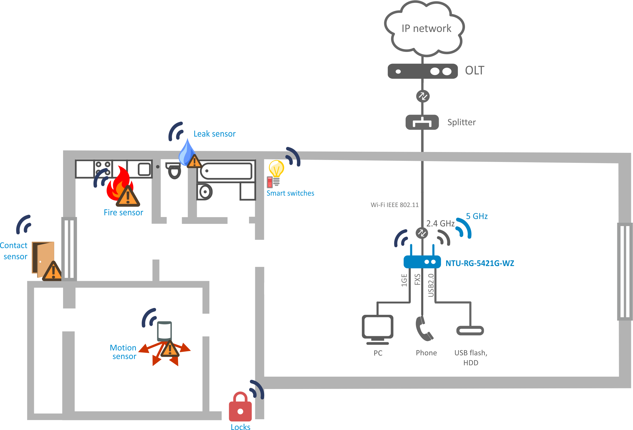
Figure 2 – NTU-RG-5421G-Wac, NTU-RG-5421G-WZ, NTU-RG-5440G-Wac and NTU-RG-5440G-WZ application diagram
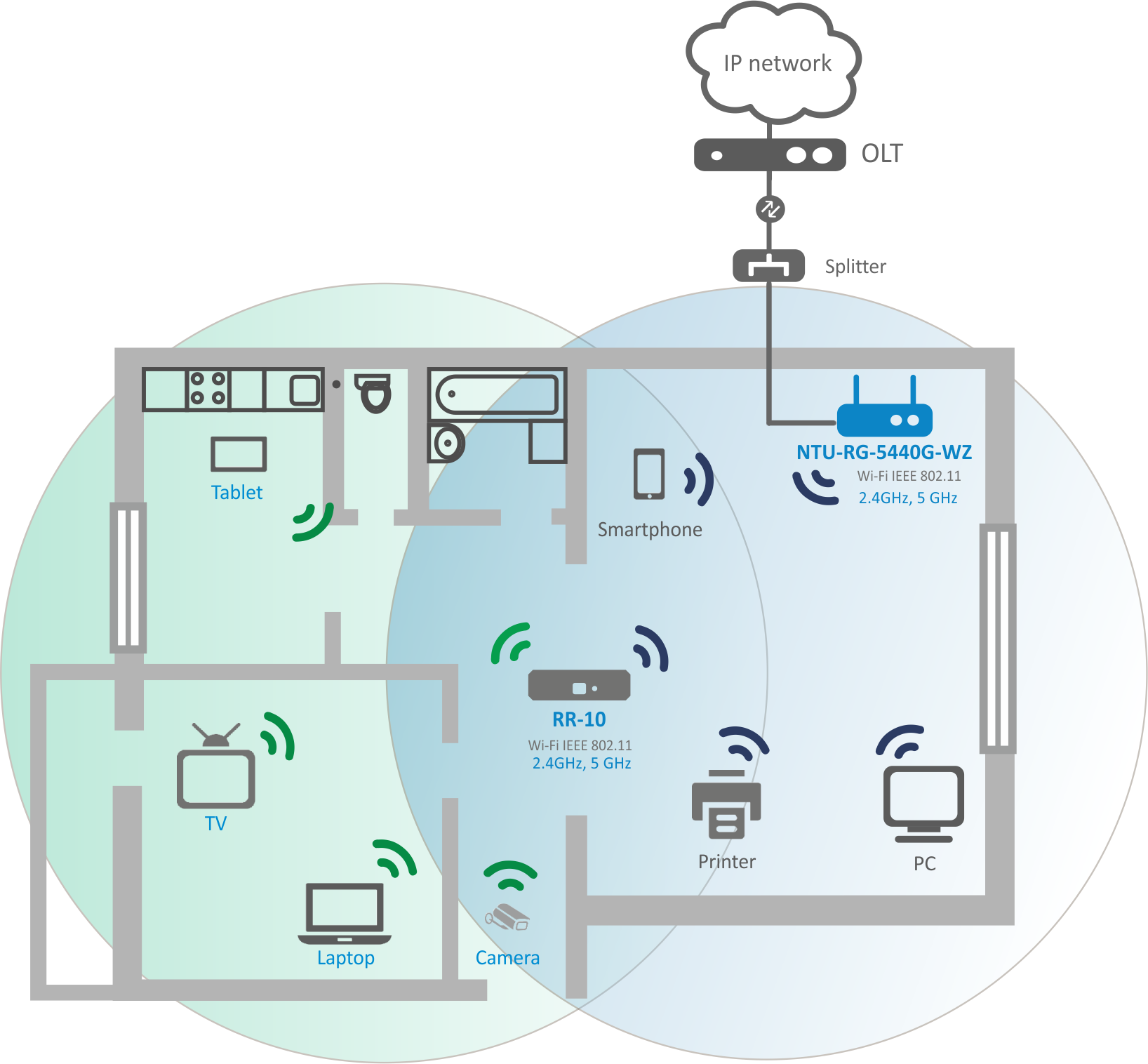
Figure 3 – NTU-RG-5421G-WZ and NTU-RG-5440G-WZ application diagram
Key Specifications
Table 2 shows main specifications of the terminals:
Table 2 – Main Specifications
VoIP protocols
Supported protocols | SIP |
|---|
Audio codecs
Codecs | G.729, annex A |
|---|
Parameters of Ethernet LAN interfaces
Number of interfaces | 4 |
|---|---|
Connector type | RJ-45 |
Data transfer rate, Mbps | Autonegotiation, 10/100/1000 Mbps, |
Standards | IEEE 802.3i 10Base-T Ethernet |
Parameters of PON interface
Number of interfaces | 1 |
|---|---|
| Standards | ITU-T G.984.x Gigabit-capable passive optical networks (GPON) ITU-T G.988 ONU management and control interface (OMCI) specification IEEE 802.1Q Tagged VLAN IEEE 802.1P Priority Queues IEEE 802.1D Spanning Tree Protocol |
| Connector type | SC/APC in accordance with ITU-T G.984.2, ITU-T G.984.5 Filter, FSAN Class B+, SFF-8472 |
| Transmission medium | Fiber optical cable SMF - 9/125, G.652 |
| Splitting ratio | Up to 1:128 |
| Maximum range of coverage | 20 km |
| Transmitter: | 1310 nm |
| 1244 Mbps |
| from +0,5 to +5 dBm |
| 1 nm |
| Receiver: | 1490 nm |
| 2488 Mbps |
| from -8 to -28, BER≤1.0x10⁻¹⁰ |
| Receiver optical congestion | -8 dBm |
Parameters of subscriber analogue ports
| Number of ports | NTU-RG-5402G-W | NTU-RG-5421G-Wac NTU-RG-5421GC-Wac NTU-RG-5421G-WZ |
|---|---|---|
| 2 | 1 | |
| Loop resistance | Up to 2 kΩ | |
| Call reception | Pulse/frequency (DTMF) | |
| Caller ID display | Yes | |
Wi-Fi interface parameters
| Model | NTU-RG-5402G-W | NTU-RG-5421G-Wac | NTU-RG-5440G-Wac NTU-RG-5440G-WZ |
|---|---|---|---|
| Standard | 802.11 b/g/n | 802.11 a/b/g/n/ac | 802.11 a/b/g/n/ac |
| Frequency range | 2400 ~ 2483,5 MHz | 2400 ~ 2483,5 MHz, 5150 ~ 5350 MHz, 5650 ~ 5850 MHz | |
| Modulation | CCK, BPSK, QPSK, 16 QAM, 64 QAM, 256 QAM | CCK, BPSK, QPSK, 16 QAM, 64 QAM, 256 QAM | |
| Data transfer rate, Mbps | – 802.11b/g/n: 1-13 | – 802.11b/g/n: 1-13 | – 802.11b/g/n: 1-13 – 802.11b: 1; 2; 5.5 and 11 Mbps – 802.11g: 6, 9, 12, 18, 24, 36, 48 and 54 Mbps – 802.11ac: 1733 Mbps (80 MHz) |
| Maximum transmitter output power | – 802.11b (11 Mbps): 17 dBm | – 802.11b (11 Mbps): 17 dBm | 2.4 GHz: – 802.11b (11 Mbps): 18 dBm – 802.11g (54 Mbps): 16 dBm – 802.11n (MCS7): 16 dBm – 802.11n (MCS0): 18 dBm 5 GHz: – 802.11ac (MCS7): 18 dBm – 802.11ас (MCS0): 20 dBm |
| MAC protocol | CSMA/CA model of ACK 32 MAC | ||
| Security | 64/128-bit WEP encryption; | ||
| MIMO | 2,4 GHz- 2х2 | 2,4 GHz- 2х2, 5 GHz - 2х2 | 2,4 GHz- 2х2, 5 GHz - 4х4 |
| Antenna gain | 5 dBi | ||
| Operating temperature range | from +5 to +40°C | ||
Control
| Local control | Web interface |
|---|---|
| Remote control | Telnet, TR-069, OMCI |
| Firmware update | OMCI, TR-069, HTTP |
| Access resriction | By password |
General parameters
| Model | NTU-RG-5402G-W | NTU-RG-5421GC-Wac | NTU-RG-5440G-Wac NTU-RG-5440G-WZ | |
|---|---|---|---|---|
| Power supply | 12 V DC/220 AC power adapter | |||
| Max. power consumption | 18 W | |||
| Operating temperature range | From +5 to +40°C | |||
| Relative humidity | Up to 80% | |||
| Dimensions | 187x120x32 mm | 220x120x50 mm | 234x133x34 mm | |
| Weight | 0,3 kg | 0,45 kg | 0,57 kg | |
Design
Subscriber terminal is designed as desktop device in plastic housing.
The rear panel layout of the device is depicted in Figures 4 , 5 , 6 , 7 .
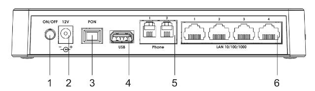
Figure 4 – NTU-RG-5402G-W-Wac rear panel layout
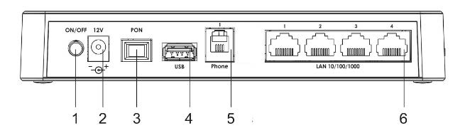
Figure 5 – NTU-RG-5421G-Wac and NTU-RG-5421G-WZ rear panel layout
The connectors and controls located on the NTU-RG-5402G-W, NTU-RG-5421G-Wac and NTU-RG-5421G-WZ rear panel are listed in Table 3.
Table 3 – Description of the connectors and controls on the rear panel
№ | Rear panel element | Description |
|---|---|---|
1 | On/Off | Power button |
2 | 12V | Power adapter connector |
3 | PON | SC port (socket) for PON with GPON interface |
4 | USB | Connector for external drives and other USB devices |
5 | Phone | RJ-11 connector for analogue phone connection:
|
6 | LAN 10/100/1000 1..4 | 4 RJ-45 ports for connection to network devices |
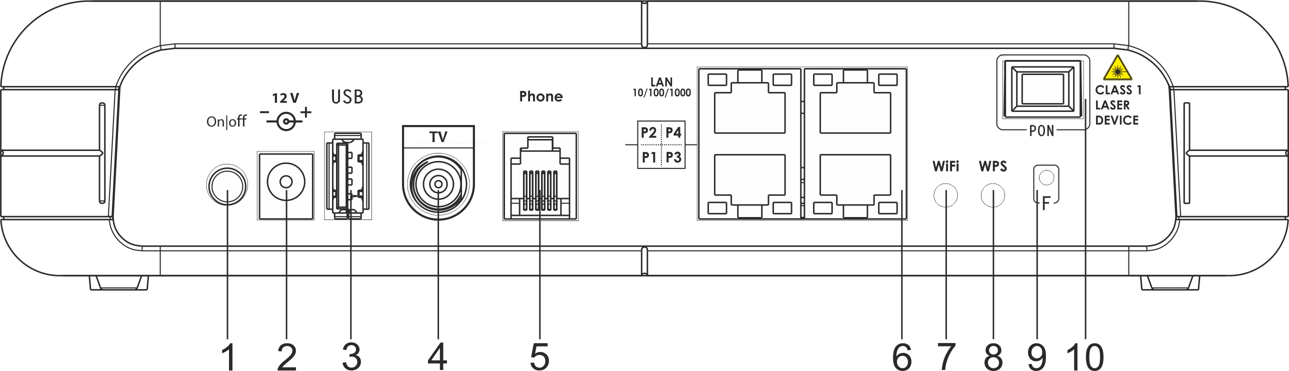
Figure 6 – NTU-RG-5421GC-Wac rear panel layout
Connectors and controls located on the rear panel of the device are listed in Table 4.
Table 4 – Description of the connectors and controls on the rear panel
№ | Rear panel element | Description |
|---|---|---|
1 | On/Off | Power button |
2 | 12V | Power adapter connector |
3 | USB | Connector for external drives and other USB devices |
4 | TV | RF port for connecting a coaxial cable |
5 | Phone | RJ-11 connector for analogue phone connection |
6 | LAN 10/100/1000 P1..P4 | 4 RJ-45 ports for connection to network devices |
| 7 | Wi-Fi | Wi-Fi enabling/disabling button |
| 8 | WPS | A button which enables automatic secure Wi-Fi connection |
| 9 | F | A functional key that reboots the device and resets it to factory settings |
| 10 | PON | SC port (socket) for PON with GPON interface |

Figure 7 – NTU-RG-5440G-Wac and NTU-RG-5440G-WZ rear panel layout
The connectors and controls located on the NTU-RG-5440G-Wac and NTU-RG-5440G-WZ rear panel are listed in Table 5.
Table 5 – Description of the connectors and controls on the rear panel
№ | Rear panel element | Description |
|---|---|---|
| 1 | F | A functional key to reboot the device and reset it to factory settings |
2 | On/Off | Power button |
3 | 12V | Power adapter connector |
4 | LAN 10/100/1000 1..4 | 4 RJ-45 ports for connection to network devices |
5 | PON | SC port (socket) for PON with GPON interface |
6 | USB | Connector for external drives and other USB devices |
7 | Wi-Fi | Wi-Fi enabling/disabling button |
8 | WPS | A button to enable automatic secure Wi-Fi connection |
Figure below shows NTU-RG-5402G-W, NTU-RG-5421G-Wac and NTU-RG-5421G-WZ side panel layout.
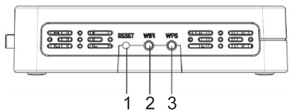
Figure 8 – NTU-RG-5402G-W, NTU-RG-5421G-Wac and NTU-RG-5421G-WZ side panel layout
See Table 6 for detailed information about buttons located on the side panel of the device.
Table 6 – NTU-RG-5402G-W, NTU-RG-5421G-Wac and NTU-RG-5421G-WZ side panel buttons description
№ | Rear panel element | Description |
|---|---|---|
1 | Reset | A functional key to reboot the device and reset it to factory settings |
2 | Wi-Fi | Wi-Fi enabling/disabling button |
3 | WPS | A button to enable automatic secure Wi-Fi connection |
Light Indication
Figure 9 shows NTU-RG-5402G-W, NTU-RG-5421G-Wac and NTU-RG-5421G-WZ top panel layout.
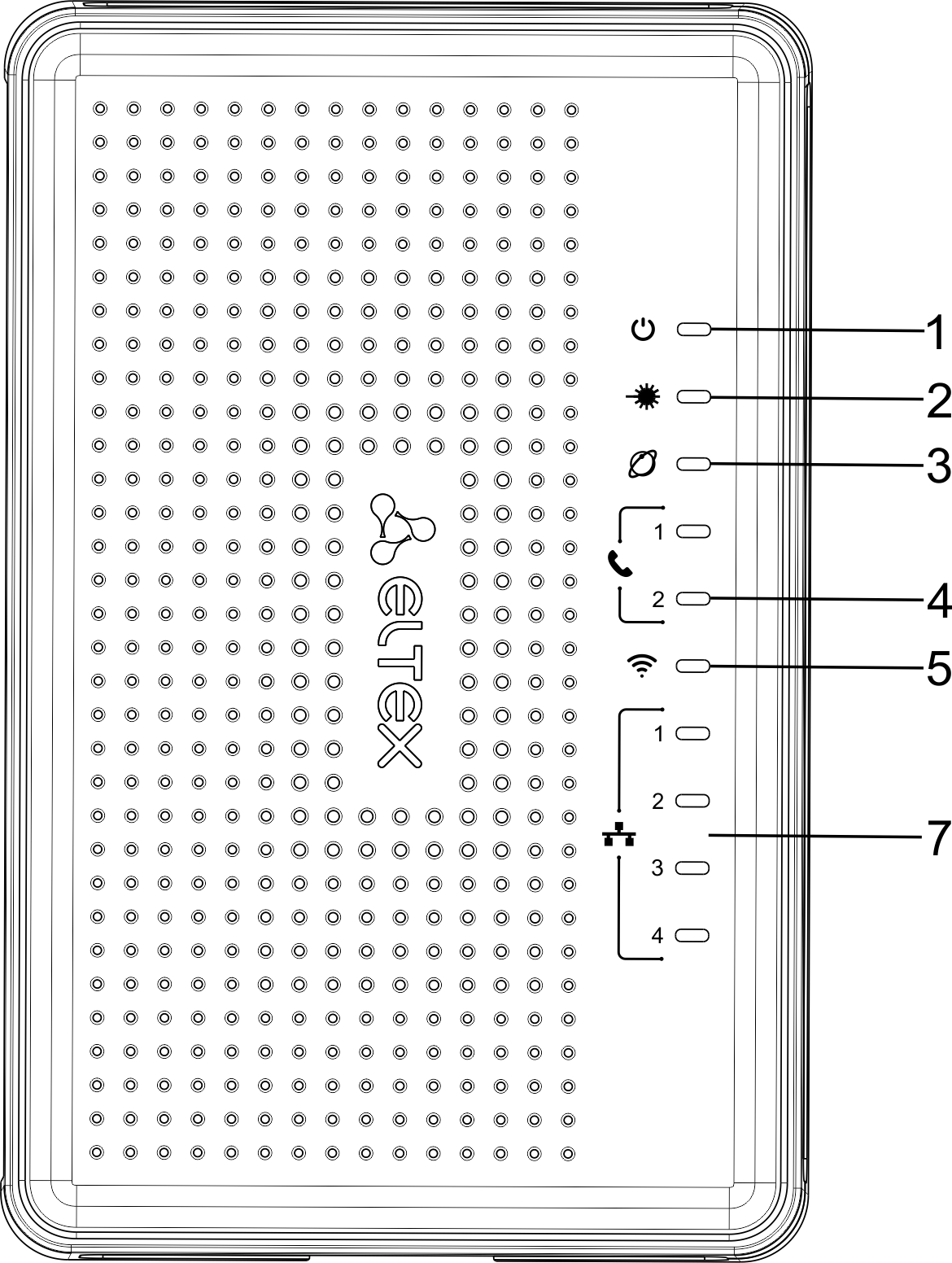
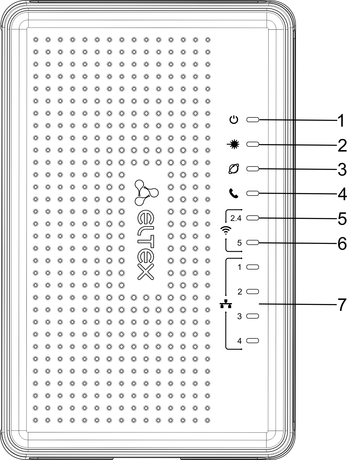
Figure 9 – NTU-RG-5402G-W (on the left) and NTU-RG-5421G-Wac, NTU-RG-5421G-WZ (on the right) top panel layout
Current status of the device is represented by means of indicators paced on the top panel. Table 7 provides possible statuses of the LEDs.
Table 7 – Description of NTU-RG-5402G-W, NTU-RG-5421G-Wac and NTU-RG-5421G-WZ top panel LEDs
№ | Top panel element | LED status | Description |
|---|---|---|---|
1 |
| off | device is disconnected from the power source or faulty |
| red | device startup is in progress | ||
| green | device startup completed, the current device configuration differs from the default one | ||
| orange | device startup is completed, the default configuration is set | ||
2 |
| off | device booting |
| green | connection between optical line terminal and the device has been established | ||
| flashes green | connection between optical line terminal and the device has been established (the device is not activated) | ||
| flashes red | no signal from optical line terminal | ||
3 |
| off | Internet interface is not configured |
| green | device is ready for operation, Internet connection is established | ||
| flashes green slowly | device firmware update is in progress | ||
| flashes green rapidly | device booting/connection to the Internet is being established | ||
4 |
| off | SIP agent is not configured/not registered/off |
| on | SIP agent is successfully registered | ||
| flashes | off hook/phone call | ||
5 |
| green | Wi-Fi network is active |
| flashes | transmitting data via Wi-Fi | ||
| off | Wi-Fi network is inactive | ||
6 |
| green | Wi-Fi network is active |
| flashes | transmitting data via Wi-Fi | ||
| off | Wi-Fi network is inactive | ||
7 |
| green | established 10/100 Mbps connection |
| orange | established 1000 Mbps connection | ||
| flashes | transferring data packets |
The front panel of NTU-RG-5421GC-Wac is shown in Figure 10.
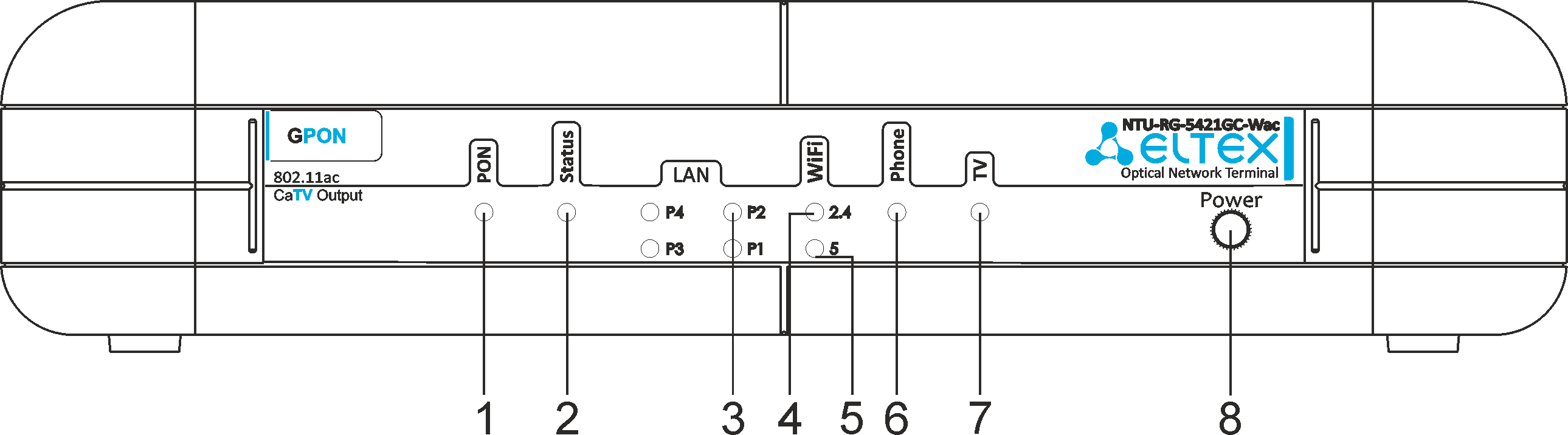
Figure 10 – NTU-RG-5421GC-Wac front panel layout
The LED indicators located on the front panel show the current state of the device. The list of indicator states is shown in Table 8.
Table 8 – Description of NTU-RG-5421GC-Wac front panel LEDs
| № | Front panel element | LED status | Description |
|---|---|---|---|
| 1 | PON – optical interface activity indicator | off | device booting |
| green | connection between optical line terminal and the device has been established | ||
| flashes green | connection between optical line terminal and the device has been established (the device is not activated) | ||
| flashes green rapidly | device booting/connection to the Internet is being established | ||
| flashes red | no signal from optical line terminal | ||
| 2 | Status – status indicator | off | Internet interface is not configured |
| green | device is ready for operation, Internet connection is established | ||
| flashes green slowly | device firmware update is in progress | ||
| 3 | LAN P1..P4 – Ethernet port activity indicator | green | established 10/100 Mbps connection |
| orange | established 1000 Mbps connection | ||
| flashes | transferring data packets | ||
| 4 | WiFi 2.4 – Wi-Fi activity indicator for 2.4 GHz | green | Wi-Fi network is active |
| flashes | transmitting data via Wi-Fi | ||
| off | Wi-Fi network is inactive | ||
| 5 | WiFi 5 – Wi-Fi activity indicator for 5 GHz | green | Wi-Fi network is active |
| flashes | transmitting data via Wi-Fi | ||
| off | Wi-Fi network is inactive | ||
| 6 | Phone – FXS port activity indicator | off | SIP agent is not configured/not registered/off |
| on | SIP agent is successfully registered | ||
| flashes | off hook/phone call | ||
| 7 | TV – TV operation status indicator | green | 8dBm < CATV signal power < +2dBm |
| off | RF port is disabled | ||
| red | TV signal is not available | ||
| orange | signal level is not normal (more than +2 dBm) | ||
| 8 | Power – power and operation status indicator | off | device is disconnected from the power source or faulty |
| red | device startup is in progress | ||
| green | device startup completed, the current device configuration differs from the default one | ||
| orange | device startup is completed, the default configuration is set |
Figure 11 shows NTU-RG-5440G-Wac, NTU-RG-5440G-WZ top panel layout.
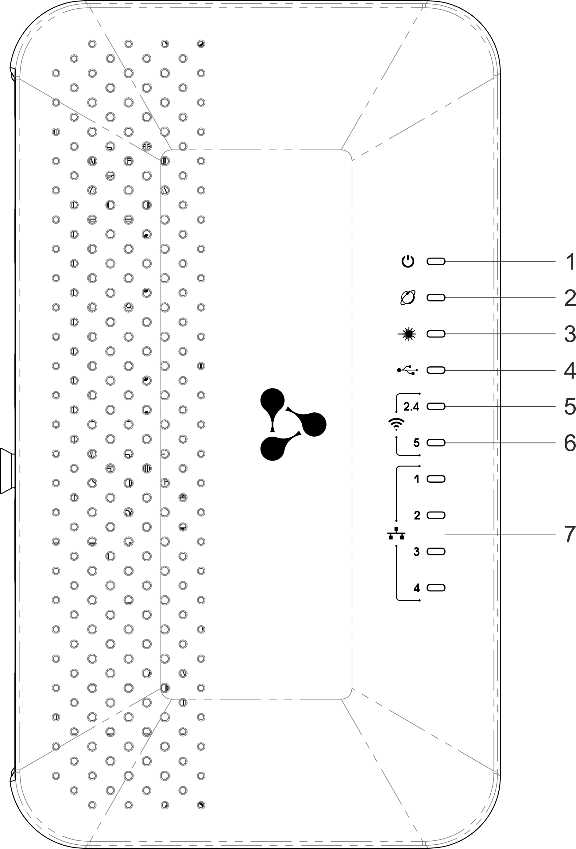
Figure 11 – NTU-RG-5440G-Wac and NTU-RG-5440G-WZ top panel layout
Current status of the device is represented by means of indicators paced on the top panel. Table 9 provides possible statuses of the LEDs.
Table 9 – Description of NTU-RG-5440G-Wac and NTU-RG-5440G-WZ top panel LEDs
№ | Top panel element | LED state | Description |
|---|---|---|---|
1 |
| off | device is disconnected from the power source or faulty |
| red | device startup is in progress | ||
| green | device startup completed, the current device configuration differs from the default one | ||
| orange | device startup is completed, the default configuration is set | ||
| 2 |
| off | Internet interface is not configured |
| green | device is ready for operation, Internet connection is established | ||
| flashes green slowly | device firmware update is in progress | ||
| flashes green rapidly | device booting/connection to the Internet is being established | ||
3 |
| off | device booting |
| green | connection between optical line terminal and the device has been established | ||
| flashes green | connection between optical line terminal and the device has been established (the device is not activated) | ||
| flashes red | no signal from optical line terminal | ||
4 |
| off | USB device is not connected |
| on | USB device is connected | ||
| flashes | USB data transfer process | ||
5 |
| green | Wi-Fi network is active |
| flashes | transmitting data via Wi-Fi | ||
| off | Wi-Fi network is inactive | ||
6 |
| green | Wi-Fi network is active |
| flashes | transmitting data via Wi-Fi | ||
| off | Wi-Fi network is inactive | ||
7 |
| green | established 10/100 Mbps connection |
| orange | established 1000 Mbps connection | ||
| flashes | transferring data packets |
Indication of LAN Interfaces
Table 10 lists operation modes shown by LAN ports LEDs located on the rear panel of the device.
Table 10 – Light Indication of LAN Interfaces
Operation modes | Yellow LED | Green LED |
|---|---|---|
Port operates in 1000Base-T mode, data transfer is inactive | solid on | off |
Port operates in 1000Base-T mode, data transfer is active | flashes | off |
Port operates in 10/100Base-TX, data transfer is inactive | off | solid on |
Port operates in 10/100Base-TX, data transfer is active | off | flashes |
Reboot and Reset to Factory Settings
For device reboot, press the «Reset» button once
- on the device side panel for NTU-RG-5402G-W, NTU-RG-5421G-Wac and NTU-RG-5421G-WZ;
- the «F» button on the device rear panel for NTU-RG-5421GС-Wac, NTU-RG-5440G-Wac, NTU-RG-5440G-WZ.
In order to reset the device to the factory settings, press the «Reset» button and hold it for 7-10 seconds until the indicator glows red and all other LEDs go out. Factory settings for IP address are: LAN – 192.168.1.1, subnet mask – 255.255.255.0. Access can be provided from LAN 1, LAN 2, LAN 3 and LAN 4 ports.
Delivery Package
The NTU-RG standard delivery package includes:
- NTU-RG optical network terminal;
- 220V/12V power adapter.
NTU-RG architecture
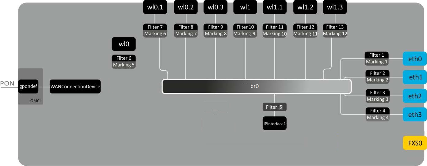
Figure 12 – Logical Architecture of a Device with Factory Settings
Main Components of the Device:
- Optical receiver/transmitter (SFF module) for conversion of an optical signal into an electric one;
- Processor (PON chip) which converts Ethernet and GPON interfaces;
- Wi-Fi modulesfor wireless interfaces of the device.
A device with factory (initial) settings have the following logical blocks (see Figure 12 ):
- Br0;
- Voice (VoIP block);
- eth0…3;
- FXS0;
- wl0, wl0.1, wl0.2, wl0.3, wl1, wl1.1, wl1.2, wl1.3;
- IPInterface1.
Br0 block here is used to combine LAN ports into a single group.
Eth0..3 blocks physically represent Ethernet ports with RJ-45 connector for connection of PC, STB, and other network devices. They are logically included into br0 block
FXS0 block is a port with RJ-11 connectors for connection of analogue phone. It is logically included into the Voice block. The Voice block can be controlled through web interface or remotely with ACS server via TR-069 standard. The block specifies VoIP service parameters (SIP server address, phone number, VAS, etc.).
wl0, wl0.1…wl1.3 blocks for Wi-Fi modules connection. Wl0 blocks are interfaces for 2.4 GHz operation, wl1ones – for 5 GHz operation.
Filter and Marking blocks enable inclusion of local interfaces into a single group (to br0 block). They deal with the traffic transmission rules, Filter blocks are responsible for the incoming traffic on the interface, Marking blocks – for the outgoing one.
IPInterface1 block is a logical entity on which IP address providing the access in LAN and DHCP server distributing addresses to clients are located.
Device configuration via Web interface. Administrator Access
Getting Started
To configure the device, it is necessary to connect to it through Web browser:
- Open the Web browser (program for viewing hypertext documents), for example, Firefox, Google Chrome and etc.
You should enter the device IP address in the browser address line
The default IP-address of the device – 192.168.1.1, subnet mask – 255.255.255.0
When the device is successfully connected, username and password request page will be shown in the browser window:
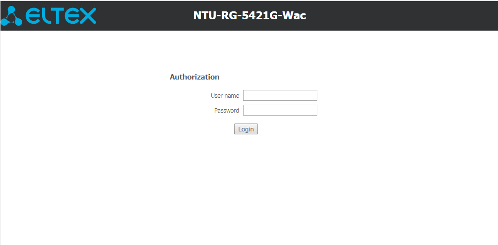
Enter your username into ‘User Name’ and password into ‘Password’ field.
Username: user, password: user.
- Click the ‘Login’ button. In the browser window, the home page of the device’s web interface will open.
Password changing
To prevent unauthorized access to device in the future, it is recommended to change password. To change the password enter the current password in the «Old Passowrd» field and the new password in the «New Password» and «Confirm new password» fields in the «Admin» menu, «Password» section. To save the changes, click the «Apply Changes» button.
Main elements of the web interface
General view of the device configuration window is depicted below.
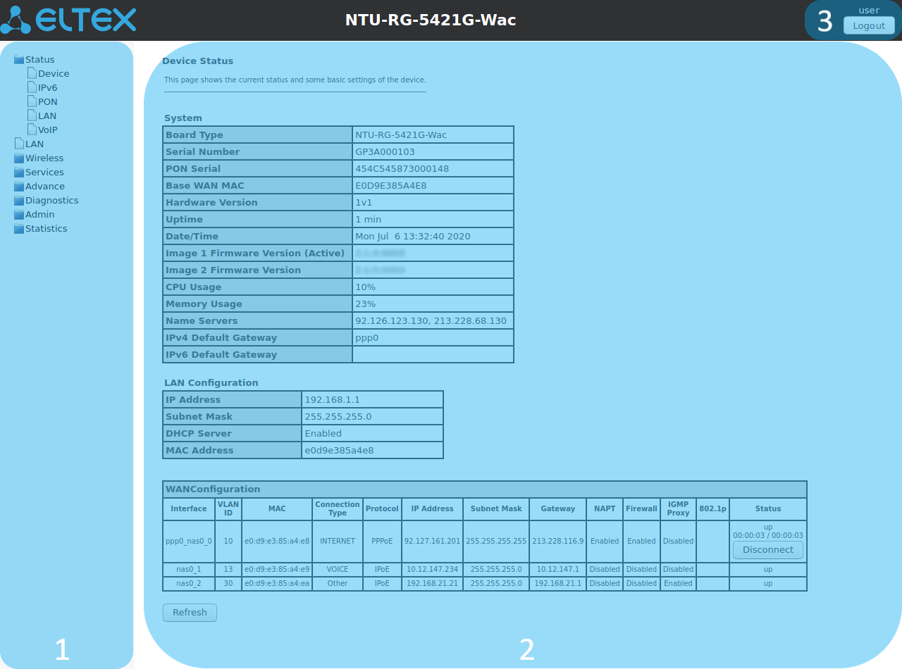
The user interface window can be divided into 3 parts:
- The navigation tree on the device settings menu.
- The main settings window for the selected section.
- User change button.
The «Status» menu. Device Information
The «Device status» submenu. Device General Information
This section displays general information about the device, the main parameters of the LAN and WAN interfaces.
Status → Device status
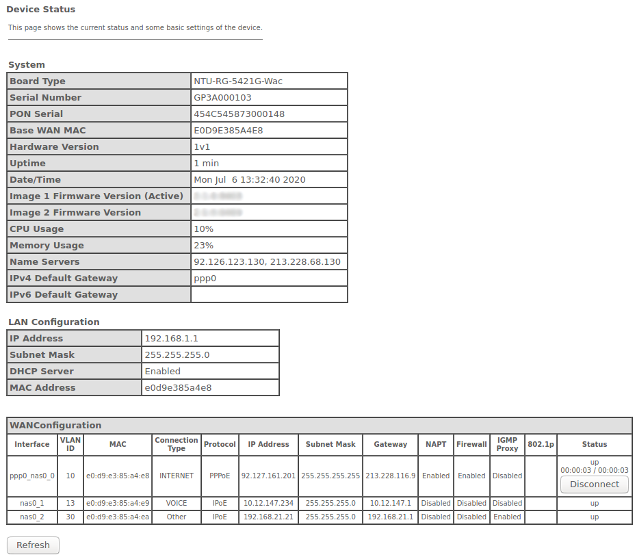
System
- Board Type – device model;
- Serial Number – device serial number;
- PON Serial – device serial number in the PON network;
- Base WAN MAC – device WAN MAC address;
- Hardware Version – hardware version;
- Uptime – device uptime;
- Date/Time – current time on the device;
- Image 1 Firmware Version (Active) – current firmware version;
- Image 2 Firmware Version – backup firmware version;
- CPU Usage – CPU utilization percent;
- Memory Usage – Memory utilization percent;
- Name Servers – DNS server name;
- IPv4 Default Gateway – IPv4 default gateway;
- IPv6 Default Gateway – IPv6 default gateway.
LAN Configuration
- IP Address – device IP address;
- Subnet Mask – device subnet mask;
- DHCP Server – DHCP server state;
- MAC Address – device MAC address.
WAN Configuration
- Interface – interface name;
- VLAN ID – interface VLAN ID;
- MAC – interface MAC address;
- Connection Type – connection type;
- Protocol – protocol used;
- IP Address – interface IP address;
- Gateway – gateway;
- Status – interface status.
Click the «Refresh» button to update the page.
The «IPv6 Status» submenu. Information about IPv6 system
The tab displays the current status of IPv6 system.
Status → IPv6
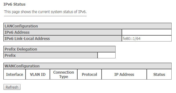
LAN Configuration
- IPv6 Address – IPv6 address;
- IPv6 Link-Local Address – local IPv6 address.
Prefix Delegation
- Prefix – IPv6 address prefix.
WAN Configuration
- Interface – interface name;
- VLAN ID – interface VLAN ID;
- Connection Type – connection type;
- Protocol – protocol used;
- IP Address – interface IP address;
- Status – interface status.
Click the «Refresh» button to update the page.
The «PON» submenu. Optical module status information
The tab displays the current status of PON interface system.
Status → PON

PON Status
- Temperature – current temperature;
- Voltage – voltage;
- Tx Power – transmission power;
- Rx Power – reception power;
- Bias Current – bias current;
- Video Power – video signal power1.
PON Status
- ONU State – status of authorization on OLT (O1 -> O2 -> O3 -> O4 -> O5 );
- ONU ID – device identifier on OLT;
- LOID Status – status of authorization on OLT (Initial -> Standby -> Serial Number -> Ranging -> Operation).
Click the «Refresh» button to update the page.
1 Only for NTU-RG-5421GC-Wac
The «LAN» submenu. LAN interface status information
In the «LAN» section you can view the status of LAN ports of the device and Wi-Fi interfaces.
Status → LAN
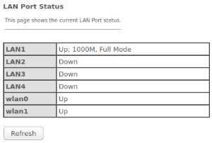
The LAN Port Status table shows:
- LAN port number;
- port state (Up/Down);
- rate of external network device connection to the port (10/100/1000 Mbps).
The «VoIP» submenu. Information on VoIP status
In the «VoIP» section you can view the status of the VoIP network interface.
Status → VoIP
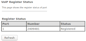
- Port – number of subscriber device set;
- Number – subscriber phone number;
- Status – state of phone number registration on proxy server.
The «LAN» menu. LAN interface configuration
You can configure main parameters of wired and wireless LAN interfaces in this menu.
LAN
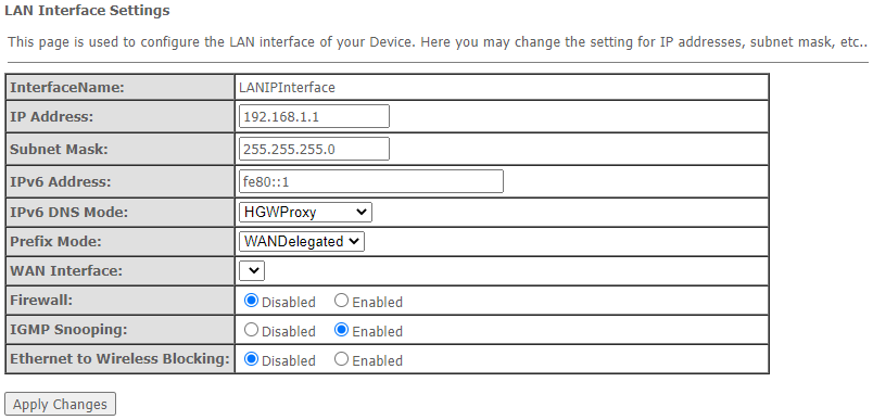
- Interface name – interface name;
- IP Address – interface IP address;
- Subnet Mask – interface subnet mask;
- IPv6 Address – IPv6 address;
- IPv6 DNS Mode – configure the domain name usage mode:
- WANConnection – use WAN interface for obtaining DNS server address;
- Static – specify static DNS server address (IPv6 DNS1, IPv6 DNS2).
- Prefix Mode – configure the Prefix reception mode (from WAN interface or statically):
- WANDelegated – enables the option of delegating the prefixes received from the ISP;
- Static – specify static Prefix.
- IPv6 DNS – specify static DNS server address (IPv6 DNS1, IPv6 DNS2);
- WAN Interface – select the WAN interface to be used for WANDelegated.
- Firewall (Enabled/Disabled) – enable/disable firewall for LAN interface;
- IGMP Snooping (Enabled/Disabled) – enable/disable IGMP Snooping;
- Ethernet to Wireless Blocking ( Enabled/Disabled) – enable/disable isolation of wired and wireless clients.
To save the changes, click the «Apply Changes» button.
The «Wireless» menu. Wireless network configuration
This section contains individual settings for each of the operating bands – 2.4 GHz (wlan0) and 5 GHz (wlan1).
The «Status» submenu. Current WLAN status
This submenu displays the current status of the WLAN.
Wireless → wlan0 (2.4GHz) / wlan1 (5GHz) → Status
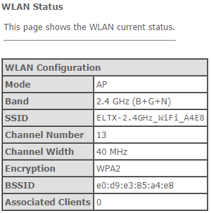
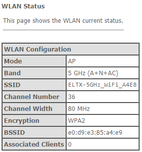
- Mode – AP - access point;
- Band – range, band, standards;
- SSID – access point network name;
- Channel Number – channel number;
- Channel Width – channel width;
- Encryption – encryption method;
- BSSID – access point MAC address;
- Associated Clients – number of connected clients.
The «Basic settings» submenu. Basic settings
This submenu is used for general setup of the WLAN wireless interface parameters and allows users to specify up to three virtual wireless access points.
Wireless → wlan0 (2.4GHz) / wlan1 (5GHz) → Basic settings
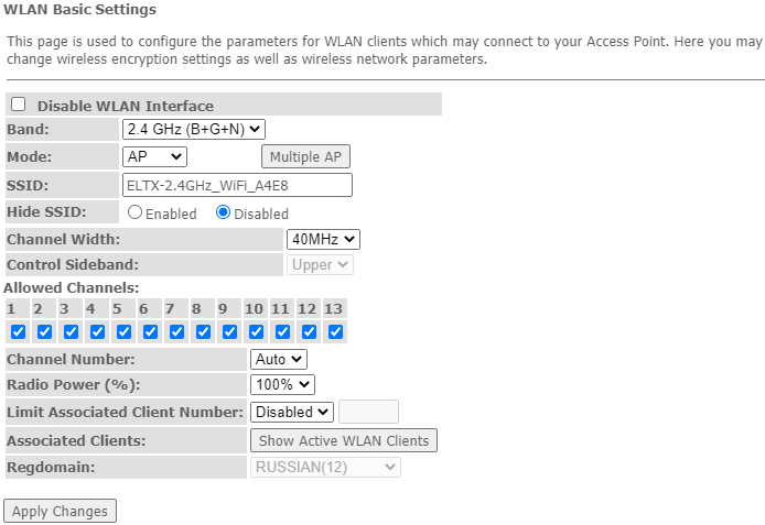
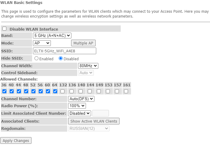
- Disable WLAN Interface – disable radio interface;
- Band – change Wi-Fi operation standard;
- Mode – access point (AP) operation mode;
- SSID (ServiceSet Identifier) – assign a wireless network name (case sensitive);
Default device SSID is ELTX-2.4GHz_WiFi__aaaa/ELTX-5GHz_WiFi_aaaa, where аааа – the last 4 digits of WAN MAC. WAN MAC is labelled on the device housing. The network name contains a frequency band (2.4/5GHz).
- Hide SSID – this feature enables the hidden wireless network identifier (SSID) mode. When using this feature, the access point will not be displayed in the list of available wireless networks on user devices (its SSID will not be visible). However, users who are aware of the existence of this network and know its SSID will be able to connect to it;
- Channel Width – 20/40 MHz bandwidth;
- Control Sideband – management sideband, select the second channel (Lower or Upper) in 40 MHz mode;
- Allowed channels – configure the Wi-Fi channels allowed to connect clients to the router. By default, all channels are allowed;
- Channel Number – select utilized channel:
- Auto – automatic channel selection.
- Radio Power (%) – transmitter power;
- Limit Associated Client Number (Enable/Disabled) – limit the maximum amount of associated clients;
- Associated Clients – maximum amount of associated clients;
- Enable Universal Repeater Mode (Acting as AP and client simultaneouly) – enable repeater mode;
- Regdomain – region settings.
To save the changes, click the «Apply Changes» button.
The «Show Active WLAN Client» button outputs the table of active WLAN clients.
Wireless → wlan0 (2.4GHz) / wlan1 (5GHz) → Basic settings → Show Active WLAN Client
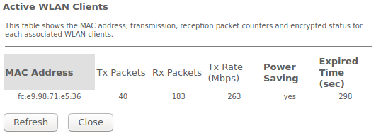
- MAC Address – MAC address of the client;
- Tx Packets – amount of packets transmitted to the client;
- Rx Packets – amount of packets received from the client;
- Tx Rate (Mbps) – channel transmission rate, Mbps;
- Power Saving – power saving mode;
- Expired Time (sec) – address leasing expiration time, s .
To update the information in the table, click the «Refresh» button, to close the table, click «Close».
The «Advanced settings» submenu. Advanced settings
In this submenu you can perform advanced configuration of wireless network.
Wireless → wlan0 (2.4GHz) / wlan1 (5GHz) → Advanced settings

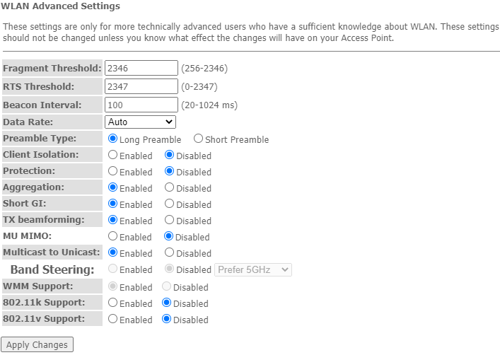
- Fragment Threshold – set the fragmentation threshold, in bytes. If a packet size exceeds the value, the packet is fragmented into parts of the corresponding size;
- RTS Threshold – if the packet is smaller than the RTS threshold value, the RTS/CTS mechanism (with request to send/clear to send packets) is not used;
- Beacon Interval – time period for transmission of informational packets, which indicate activity of the access point, to the wireless network;
- Data rate – transmission rate;
- Preamble Type – select the preamble - long (Long Preamble)/short (Short Preamble);
- Client Isolation(Enable/Disabled) – enable/disable client blocking;
- Protection (Enable/Disabled) – enable/disable 802.11n protection;
- Aggregation (Enable/Disabled) – enable/disable frames aggregation to increase the bandwidth;
- Short GI(Enable/Disabled) – enable/disable a short guard interval;
- TX beamforming (Enable/Disabled) – enable/disable adaptive beamforming;
- MU MIMO – enable/disable Multi-user MIMO mode;
- Multicast to Unicast(Enable/Disabled) – enable/disable multicast-unicast conversion;
- WMM Support(Enable/Disabled) – enable/disable the support for Wi-Fi Multimedia;
- 802.11k Support – enable/disable the Radio Resource Management option to send clients information about neighboring access points;
- 802.11v Support – enable/disable the Wireless Network Management option for data exchange between access points.
To save the changes, click the «Apply Changes» button.
The «Security» Submenu. Security Settings
Use this menu to configure general data encryption settings for a wireless network. The client wireless equipment can be configured either manually or automatically with the help of WPS.
Wireless → wlan0 (2.4GHz) / wlan1 (5GHz)→ Security
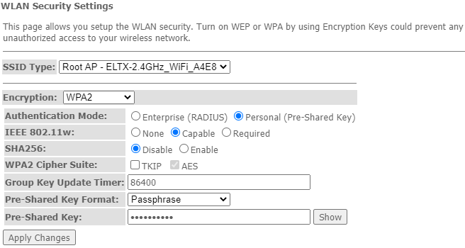

- SSID Type – current SSID;
- Encryption – set the encryption mode:
- NONE (open) – no wireless network protection;
- WEP – WEP encryption algorithm;
- WPA/WPA2/WPA2 Mixed – WPA/WPA2/WPA2 Mixed encryption algorithm.
When the «WEP» encryption mode is selected, the following settings are available:
- 802.1x Authentication – enables 802.1x standard (enables user authentication with RADIUS server, WEP key is used for data encryption);
- Authentication – select authentication mode:
- Open system – without authentication;
- Shared Key – pre-shared key authentication;
- Auto – automatic authentication.
- Key Length (encryption strength) – use 64- or 128-bit keys;
- Key Format – use ASCII or HEX format;
- Encryption Key (сетевой ключ) – 10 hex characters key or 5 ASCII characters for 64-bit encryption. Other options are 26 hex characters or 13 ASCII characters for 128-bit encryption.
When selecting WPA/WPA2/WPA2 Mixed encryption mode, the following settings will be available:
- Authentication Mode – Enterprise (RADIUS) or Personal (Pre-Shared Key) authentication mode: In the Enterprise (RADIUS) mode perform next settings:
- RADIUS Server IP Address – RADIUS server IP address;
- RADIUS Server Port – RADIUS server port number. The default port is 1812;
- RADIUS Server Password – Secret key for access to the RADIUS server;
- IEEE 802.11w – enable service frame encryption;
- None – disable service frame encryption;
- Capable – encryption compatibility mode;
- Required – encryption is required.
- SHA256 (Enable/Disable) – enable/disable SHA256 usage.
- WPA Cipher Suite – set of WPA TKIP or AES fonts;
- Group Key Update Timer – key update timer;
- Pre-Shared Key Format – key format: ASCII or HEX;
- Pre-Shared Key – access key.
To see the encrypted access key, click the «Show» button. To save the changes, click the «Apply Changes» button.
The «Access Control» Submenu. Access settings
The menu allows filtering configuration for MAC addresses. All added MAC addresses will be displayed in Current Access Control List. When selecting the «Allowed Listed» mode, only those MAC addresses that are in the Current Access Control List can connect to the access point. When the «Deny Listed» mode is selected, all MAC addresses except those specified in the Current Access Control List will have access. To change the mode, click the «Apply Changes» button.
Wireless → wlan0 (2.4GHz) / wlan1 (5GHz) → Access control
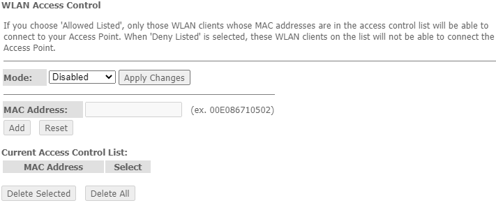
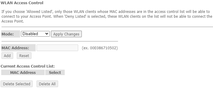
- Mode – MAC filtering mode:
- Disabled – filter is not used;
- Allowed Listed – filtering on the basis of allowed addresses (white list);
- Deny Listed – filtering on the basis of denied addresses (black list).
- MAC Address– field to add MAC address to the filtering table. To enter the value, click «Add» or click «Reset» to reset the value.
To remove selected items in the list, click «Delete Selected»; click «Delete All» to remove the whole list.
The «Wi-Fi radar» submenu. Wireless network scanning
Use this menu to scan a wireless network and to detect nearby access points or IBSS.
Wireless → wlan0 (2.4GHz) / wlan1 (5GHz) → WiFi radar
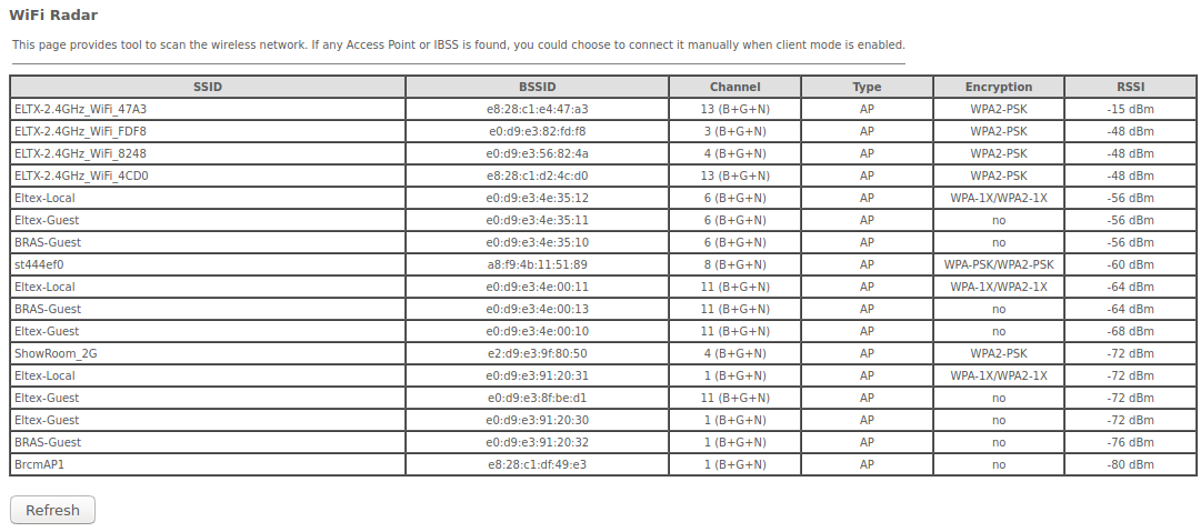
The table displays the following information:
- SSID – wireless access point name;
- BSSID – access point MAC address;
- Channel – channel;
- Type – type (AP (Access Point), Client);
- Encryption – encryption method;
- RSSI – received signal level.
To scan the environment, click the «Refresh» button.
The «EasyMesh Settings» submenu. EasyMesh feature configuration
This section configures the EasyMesh feature at the access point. The new Wi-Fi standard EasyMesh will allow you to build networks that combine mobile devices and IoT gadgets.
Wireless → EasyMesh → EasyMesh Settings
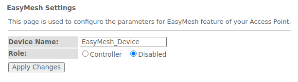
- Device name – device name;
- Role – select operation mode: disabled or controller mode.
To save the changes, click the «Apply Changes» button.
The «Topology» submenu. View EasyMesh topology
This section describes the mesh network scheme when the «Controller» mode is enabled, with specified: device name, device MAC address, device IP address.
Wireless → EasyMesh → Topology

Click the «Refresh» button to update the page.
The «WPS» submenu. Easy connection to Wi-Fi network
This section configures WPS (Wi-Fi Protected Setup) connection.
Wireless → wlan0 (2.4GHz) / wlan1 (5GHz) → WPS
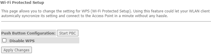
- Push Button Configuration – activate the WPS function on the router to connect subscribers;
- Disable WPS – disable the possibility of connecting to the router using WPS technology.
To save the changes, click the «Apply Changes» button.
The Services menu. Service configuration
The «DHCP Setting» submenu. DHCP configuration
The menu allows DHCP server and DHCP repeater configuration.
Services → DHCP (Server)
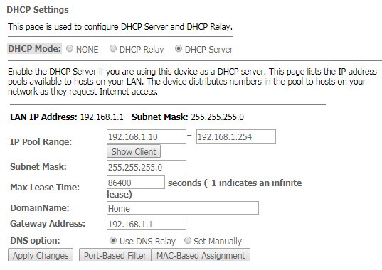
- DHCP Mode – select operation mode:
- NONE – DHCP disabled;
- DHCP Server – operation in DHCP server mode;
- DHCP Relay – operation in DHCP repeater mode.
- IP Pool Range – range of addresses distributed among clients;
- Show Client – button to view clients who leased the addresses. When clicking, a table with information about DHCP clients leased by a DHCP server is displayed;
- Subnet Mask – subnet mask;
- Max Lease Time – maximum lease time, -1 for endless lease;
- DomainName – domain name;
- Gateway Address – gateway address;
- DNS option – defines DNS operation:
- Use DNS relay – ONT address will be returned as DNS and all queries will be relayed via ONT;
- Set manually – set DNS manually.
Services → DHCP (Relay)
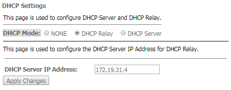
- DHCP Server IP Address – IP address of the remote DHCP server.
To save the changes, click the «Apply Changes» button. «Port-Based Filter» and «MAC-Based Assignment» buttons allow configuring port-based and MAC-based filtering, respectively.
The «Dynamic DNS» submenu. Dynamic DNS Configuration
Dynamic DNS (domain name system) allows information to be updated on DNS server in real time and (optionally) automatically. It is applied for assignment of a constant domain name to a device (computer, router, e. g. NTP-RG) having a dynamic IP address. The IP address can be assigned by IPCP in PPP connections or in DHCP.
Dynamic DNS is frequently used in local networks where clients are obtaining IP addresses through DHCP and then are registering their names on a local DNS server.
Services → DNS → Dynamic DNS
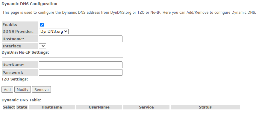
- Enable – when selected, enable DHCP server (IP addresses from the following range will be dynamically assigned to network devices);
- D-DNS Provider – select the type of D-DNS service (provider): org, TZO.com, No-IP.com;
- Custom – another provider selected by user. In this case, you need to specify the provider's name (Hostname) and address (Interface).
DynDns/No-IP Settings:
- UserName – user name;
- Password – authorization password on the service selected for operation with D-DNS.
«Dynamic DNS Table» table with the list of available DNS displayed in this section. To add a record, click the «Add» button. To remove/modify a record, click the «Remove»/«Modify» button for the selected record.
The «Firewall» submenu. Firewall configuration
The «ALG On-Off Configuration» submenu. Enable/disable ALG services
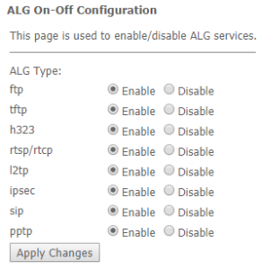
This section is used to enable/disable ALG services.
Application-level gateway (ALG) – NAT router component that understands an application protocol, and when packets of that protocol pass through it, modifies them so that users behind the NAT can use the protocol.
Services → Firewall → ALG
The «IP/Port Filtering» submenu. Address Filtering Settings
This section is used to configure address filtering. The IP Filtering function filters router traffic by IP addresses and ports.Using these filters can be useful to protect or restrict the local network.
Services → Firewall → IP/Port Filtering
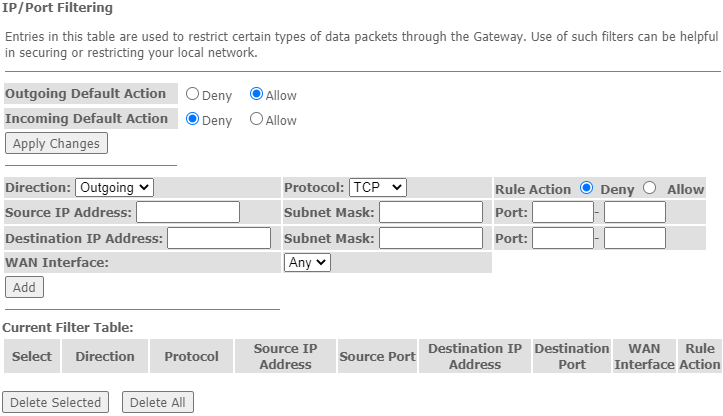
Default action
- Incoming Default Action Deny Allow – filtering for incoming packets;
- Outgoing Default Action Deny / Allow – filtering for outgoing packets.
To save the changes, click the «Apply Changes» button.
To add a filter, fill in the appropriate fields and click the «Add» button:
- Protocol – filtering protocol;
- Rule Action Deny / Allow – packet processing policy (deny/allow);
- Source IP Address – source IP address;
- Destination IP Address – destination IP address;
- Subnet mask – subnet mask;
- Port – port.
- Ingress Interface – ingress interface.
Added filters are displayed in the «Current Filter Table» located below. The entries in this table are used to restrict certain types of data packets pass through the gateway. To delete a specific filter, select the position and click the «Delete selected» button, to delete all filters click «Delete All».
The «MAC Filtering» submenu. Filtering Settings for MAC Addresses
MAC filtration allows traffic to be forwarded or blocked depending on source and destination MAC addresses. To change the mode click the «Apply Changes» button.
Services → Firewall → MAC Filtering
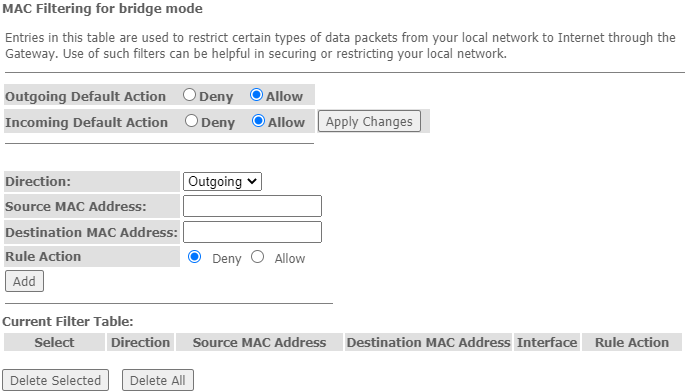
- Default Action – default settings:
- Deny – when checked, traffic pass is prohibited by default;
- Allow – when checked, traffic pass is allowed by default;
- MAC Address – MAC address for which limitation/access should be imposed.
Added filters are displayed in the «Current Filter Table» located below. The «Rule» field displays the type of created rule («Allow» - allowing or «Deny» - forbidding). To delete a specific filter, select the position and click the «Delete selected» button, to delete all filters click «Delete All».
The «Port Forwarding» submenu. Port forwarding configuration
«Current Port Forwarding Table» with port forwarding information is displayed in this section. Entries in this table allow you to automatically redirect common network services to a specific machine behind the NAT firewall. These settings are only necessary if you wish to host some sort of server like a web server or mail server on the private local network behind your router's NAT firewall. To save the changes, click the «Apply Changes» button.
Services → Firewall → Port Forwarding 
To add the entry in the «Current Port Forwarding Table» check the Enable flag and fill in the corresponding fields:
- Port Forwarding (Enable/Disable) – enable/disable port forwarding feature;
- Application – this menu has pre-settings for various applications port forwarding;
- Comment – comment;
- Local IP – local IP address to which forwarding is performed;
- Local port from/to – specify the range of local device ports for forwarding;
- Protocol – select protocol (TCP, UDP or both);
- Remote port from/to – specify the initial port of incoming connection. The «Remote port to» field will be filled automatically;
- Interface – select interface;
- NAT-loopback – NAT loop allows transferring queries from LAN to the router, thus, for example, you can check the work of rules created.
After filling the fields click the «Add» button to add the entry. To delete a selected position, click the «Delete Selected» button; to delete the whole table, click the «Delete All» button.
The «URL Blocking» submenu. Internet access restriction configuration
URL filter performs complete analysis and provides access control to specific Internet resources. This section sets and displays a list of forbidden/allowed URLs to visit. Here you can add the forbidden/allowed FQDN (Fully Qualified Domain Name) with the «Add» button, filtering by keywords is also possible. The added restrictions are displayed in the «URL Blocking Table» and the «Keyword Filtering Table». To remove a specific URL or keyword from the table, click on it and then on the «Delete Selected» button. To delete all restrictions click the «Delete All» button.
Services → Firewall → URL Blocking
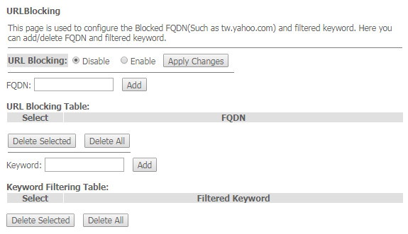
- URL Blocking (Enable/Disable) – enable/disable URL Blocking operation;
- FQDN – Fully Qualified Domain Name;
- Keyword – keyword.
To save the changes, click the «Apply Changes» button.
The «Domain Blocking» submenu. Domain blocking configuration
This section is used to set domain blocking.
Services → Firewall → Domain blocking
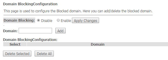
To block the domain check Enable, fill the Domain field and click the «Add» button
- Domain Blocking (Enable/Disable) – enable/disable blocking;
- Domain – domain name.
To save the changes, click the «Apply Changes» button. All blocked domains are listed in the «Domain BlockingConfiguration» table, to remove a blocking for one domain, select it and click the «Delete Selected» button, to remove all restrictions, click the «Delete All» button.
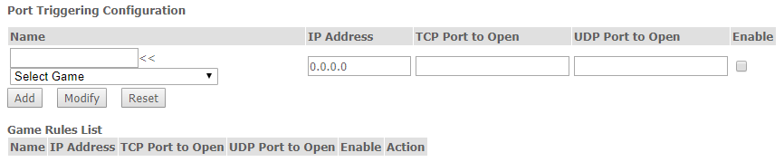
The «Port Triggering» submenu. Dynamic port opening configuration
Not supported in the current firmware version 1.2.0
When a certain event occurs, ports on its external interface are dynamically opened, which are tied to the corresponding ports on the computer on the local network.
Services → Firewall → Port Triggering
The «DMZ» submenu. Demilitarized Zone configuration
When an IP address is set in the «DMZ host IP address field», all requests from external network, that do not satisfy the «Port Forwarding» rules, will be redirected to a DMZ host (a trusted host with the specified address in the local network).
Services → Firewall → DMZ
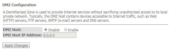
- DMZ Host (Enable/Disable) – enable/disable the host;
- DMZ Host IP Address – IP address.
To save the changes, click the «Apply Changes» button.
The «UPnP» submenu. Automated Setup of Network Devices
In this section you can configure Universal Plug and Play (UPnP™) function. UPnP ensures compatibility with network equipment, software and peripheral devices.
Services → UPnP
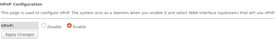
The use of UPnP requires NAT setup on an active WAN interface.
- UPnP (Enable/Disable) – enable/disable the UPnP function;
- WAN Interface – WAN interface on which the UPnP function will operate;
To save the settings, click the «Apply Changes» button.
The «RIP» submenu. Dynamic routing configuration
This section is used to select the interfaces on your device is that use RIP, and the version of the protocol used. Enable the RIP if you are using this device as a RIP-enabled Device to communicate with others using the Routing Information Protocol.
Services → RIP
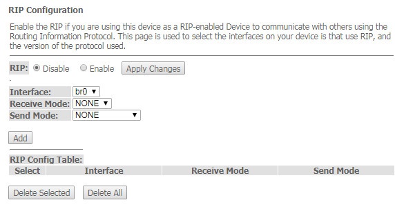
- RIP (Enable/Disable) – enable/disable the use of dynamic routing protocol RIP;
To accept and save the settings, click the «Apply Changes» button.
- Interface – interface on which RIP will be started;
- Receive Mode – incoming packets processing mode (NONE, RIP1, RIP2, both);
- Send Mode – sending mode (NONE, RIP1, RIP2, RIP1 COMPAT).
Interfaces with the support for RIP are displayed in the «RIP Config Table». To delete all entries in the table click the «Delete All» button; to delete one position from the list select it and click «Delete Selected».
The «Samba» submenu. Configuration of Samba users
In this submenu you can configure Samba users.
Services → Samba → Samba
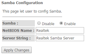
- Samba Enable/Disable – enable/disable Samba configuration;
- Server String – server name.
To save the changes, click the «Apply Changes» button.
In the «Accounts» section you can create personal Samba accounts.
Services → Samba → Accounts
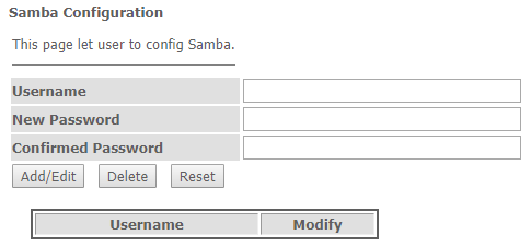
- Username – account name;
- New password – password;
- Confirmed Password – password confirmation.
The «Shares» section is used to add Samba library.
Services → Samba → Shares
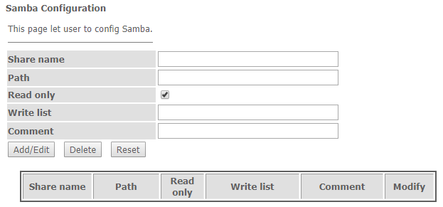
- Share name – library name;
- Path – path to library;
- Read only – read only;
- Write list – list of accounts who can change files in the library;
- Comment – comment for the library.
The «VPN» menu. Virtual private network configuration
The «L2TP» submenu. L2TP VPN configuration
This section is used to configure the parameters of L2TP VPN virtual connection. L2TP protocol is used to create a secure communication channel over the Internet between the remote user's computer and the local computer..
WAN → VPN → L2TP
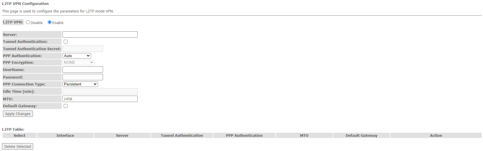
- L2TP VPN – mode in which access to the Internet is provided through a special channel, a tunnel, using L2TP. When «Enable» is checked, the following parameters become available for editing:
- Server – L2TP server address (domain name or IP address in IPv4 format);
- Tunnel Authentication – enable authentication;
- Tunnel Authentication Secret – authentication key;
- PPP Authentication – selection of connection authentication protocol used on L2TP server;
- PPP Encryption – selection of the data encryption protocol to be used (for CHAPMSv2 method only);
- UserName – user name for authorization on L2TP server;
- Password – password for authorization on L2TP server;
- PPP Connection Type – connection type;
- Idle Time (min) – idle time in seconds, breaks inactive connection after specified time (only for dial-on-demand connection);
- MTU – maximum block size of data transmitted over the network (recommended value – 1462);
- Default Gateway – selecting whether or not the created L2TP tunnel will be the default gateway.
To save the changes click the «Apply Changes» button.
In the «L2TP Table» you can view the status of L2TP VPN virtual connection. To delete a certain entry, select a position and click «Delete Selected».
The «Advance» menu. Advanced settings
The «ARP Table» menu. View ARP cache
This section shows a list of learned MAC addresses. The ARP efficiency depends a lot on ARP cache presented in every host. The cache contains Internet addresses and corresponding hardware addresses. Every record created in the cache is stored for 5 minutes.
Advance → ARP table
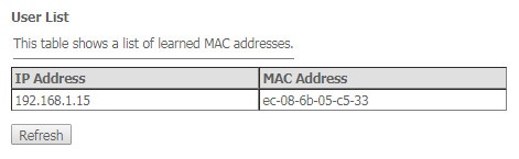
- IP Address – IP address of the client;
- MAC Address – МАС address of the client.
To update the information, click the «Refresh» button.
The «Bridging» submenu. Bridging parameters configuration
In this section you can configure bridge parameters. Here you can configure aging time of addresses in MAC table as well as to enable/disable 802.1d Spanning Tree.
Advance → Bridging
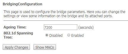
- Ageing Time – address lifetime (s);
- 802.1d Spanning Tree (Enable/Disable) – enable/disable 802.1d Spanning Tree protocol.
To save the changes, click the «Apply Changes» button.
To view the information about bridge and its connected ports click the «Show MACs» button.
Advance → Bridging → Show MACs
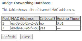
- Port – port number;
- MAC Address – MAC address;
- Is Local – local address;
- Ageing Timer – address lifetime.
To update the information in the table, click the «Refresh» button, to close the table, click «Close».
The «Routing» submenu. Routing configuration
This submenu is used to configure static routing.
Advance → Routing
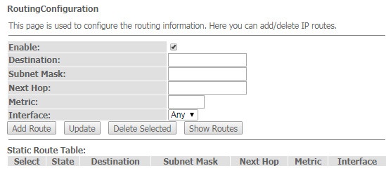
To add the static route check «Enable», fill the corresponding fields and click «Add Route».
- Enable – flag for route adding;
- Destination – destination address;
- Subnet Mask – subnet mask;
- Next Hop – next host;
- Metric – metric;
- Interface – interface.
Added static routes are displayed in the «Static Route Table». To update the information in the table, click the «Update» button, to delete the position from the table select it and click «Delete Selected».
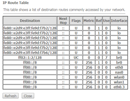
To view the routes that the device often accesses, click the «Show Routes» button, then the «IP Route Table» will be displayed.
Advance → Routing → Show Routes
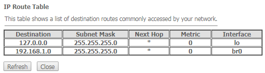
To update the information in the table, click the «Refresh» button, to close the table, click «Close».
The «Link mode» submenu. LAN ports configuration
In this submenu you can set the LAN ports operation mode. LAN1/2/3/4 – operation mode configuration; available modes: 10M Half Mode, 10M Full Mode, 100M Half Mode, 100M Full Mode and Auto Mode (auto-negotiation mode).
Advance → Link mode
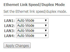
To save the changes, click the «Apply Changes» button.
The «IPv6» submenu. IPv6 configuration
In this section you can enable/disable IPv6 operation. For this you should check «Enable/Disable».
Advance → IPv6
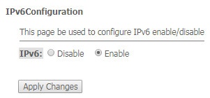
To save the changes, click the «Apply Changes» button.
The «RADVD» submenu. RADVD configuration
In this submenu you can configure RADVD (Router Advertisement Daemon).
Advance → IPv6 → RADVD
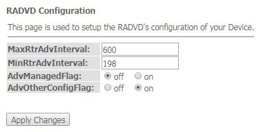
- MaxRtrAdvInterval – maximum RA (Router Advertisement) sending interval;
- MinRtrAdvInterval – minimum RA sending interval;
- AdvManagedFlag – enable/disable «Managed» flag sending in RA;
- AdvOtherFlag – enable/disable Other RA flag sending.
To save the changes, click the «Apply Changes» button.
The «DHCPv6 setting» submenu. DHCPv6 server configuration
This submenu is used to configure DHCPv6 server. By default, it operates in auto configuration mode (DHCPServer(Auto)) via prefix delegation.
Advance → IPv6 → DHCPv6
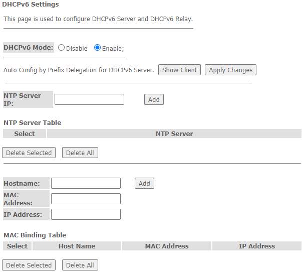
- DHCPv6 Mode – enable/disable DHCPv6 server operation;
- NTP Server IP – configure the IP address of the NTP server to synchronize time;
- Hostname – specify the hostname;
- MAC Address – specify the client's MAC address to bind the IP address;
- IP Address – specify the client's IP address to bind the MAC address;
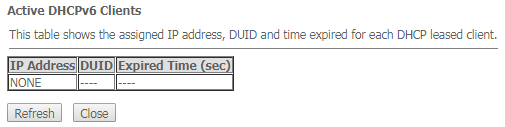
To save the changes, click the «Apply Changes» button. After clicking on the «Show Client» button, a table of active DHCPv6 server IP addresses will be displayed.
Advance → IPv6 → DHCPv6 → Show Client
The «MLD proxy» submenu. MLD proxy function configuration
In this section you can enable/disable MLD-proxy operation. For this you should check «Enable/Disable».
Advance → IPv6 → MLD proxy
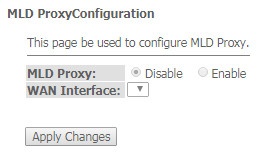
To save the changes, click the «Apply Changes» button.
The «MLD snooping» submenu. MLD snooping function configuration
In this section you can enable/disable MLD-snooping operation. For this you should check «Enable/Disable».
Advance → IPv6 → MLD snooping
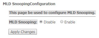
To save the changes, click the «Apply Changes» button.
The «IPv6 routing» routing. IPv6 routes configuration
This section configures static IPv6 routes.
Advance → IPv6 → IPv6 routing
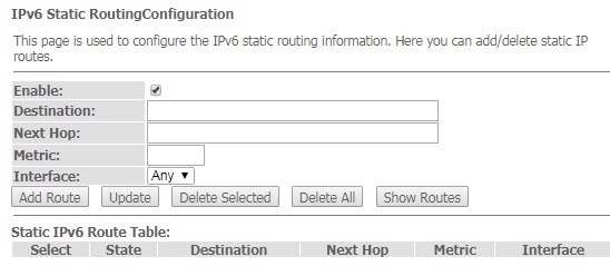
- Enable – flag for route adding;
- Destination – destination address;
- Next Hop – next host;
- Metric – metric;
- Interface – interface.
To add IPv6 Routing, fill in the appropriate fields and click the «Add Route» button: Added routes are displayed in the «Static IPv6 Route Table», to update the information click the «Update» button. To delete the whole table, click the «Delete All» button; To delete one route, select it and click the «Delete Selected» button. The «Show Routes» button displays a table of static IPv6 routes that the network typically accesses.
Advance → IPv6 → IPv6 routing → Show Routes
- Destination – destination network;
- Next Hop – nest host
- Flags – flags;
- Metric – metric;
- Ref – route source;
- Use – route usage;
- Interface – interface through which the specified route is available.
To update the table click «Refresh»; to close it click «Close»
The «IPv6 IP/Port filtering» submenu. Packet filtering configuration
Use this page to configure the filtering of data packets transmitted through the gateway.
Advance → IPv6 → IP/Port filtering
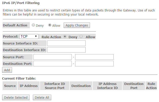
- Default Action – default action:
- Deny – when checked, traffic pass is prohibited by default;
- Allow – when checked, traffic pass is allowed by default;
- Protocol – select protocol;
- Source Interface ID – source interface;
- Destination Interface ID – destination interface;
- Source Port – source port;
- Destination Port – destination port.
To add a filter fill the corresponding fields and click the «Add» button. Added filters are displayed in the «Current Filter Table». To delete the whole table, click the «Delete All» button; To delete one filter, select it and click the «Delete Selected» button.
The «Diagnostics» submenu
Diagnostics section of access to various network nodes.
The «Ping» submenu. Checking the Availability of Network Devices
Use this menu to test the availability of network devices with Ping utility.
Diagnostics → Ping
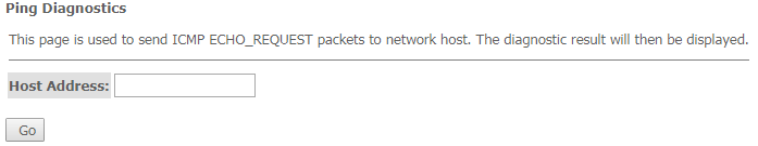
To test the availability of the connected device, enter its IP address into the «Host Address» field and click the «Go» button.
The «Traceroute» submenu
This submenu is intended for network diagnostics by sending UDP packets and receiving a message about port availability/inaccessibility.
Diagnostics → Traceroute
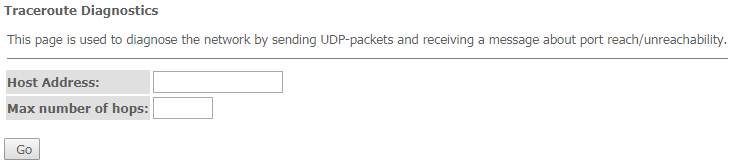
To display the path of the information packet from its source to its destination, you should enter its IP address in the «Host Address» field, specify the number of transit sections and press the «Go» button.
The «Admin» submenu
Device management section. In this menu, you can configure passwords, time, configurations, etc.
The «Settings» submenu. Configuration restore and reset
Admin → Settings → Backup Settings
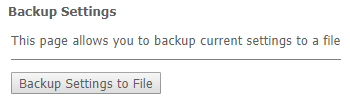
In this section, you can copy the current settings to a file (Backup Settings) by clicking on the «Backup Settings to File» button.
Admin → Settings → Update Settings
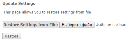
In this section, you can restore settings from a file that was previously saved (Update Settings) with the «Restore» button.
Admin → Settings → Restore Default
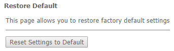
In this section you can reset the current settings to the factory default settings (Restore Default), click the «Reset Settings to Default» button.
The «GPON Setting» submenu. GPON access configuration
In this section you can specify the password for activating the terminal on OLT.
Admin → GPON Setting
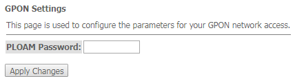
- PLOAM Password – password to activate the terminal on OLT.
To save the changes, click the «Apply Changes» button.
It is not recommended to change the activation password without consulting your ISP.
The «Commit/Reboot» submenu. Saving changes and rebooting the device
Click the «Commit and Reboot» button to reboot the device or to save changes in system memory. The rebooting process takes a few minutes to complete.
Admin → Commit/Reboot

The «Logout» submenu. Log Out
In this section it is possible to log out by clicking on the «Logout» button.
Admin → Logout

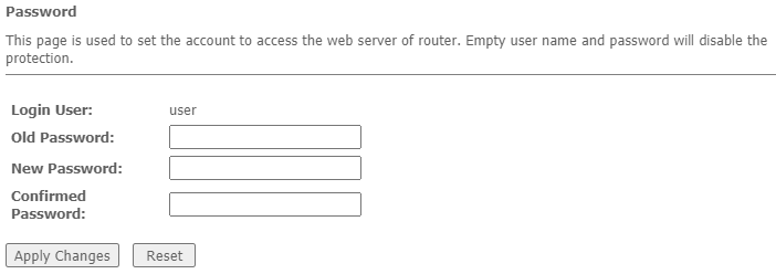
The «Password» submenu. Access control configuration (setting passwords)
In this section you can change a password to access the device.
Admin → Password
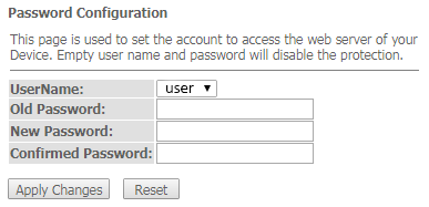
To change the password, you must enter the existing password in the «Old Password» field, then the new password in «New Password» and confirm it with «Confirmed Password».
To confirm and save changes, click the «Apply changes» button. Click the «Reset» button to reset the value.
The «Firmware upgrade» submenu. Firmware Update
To update firmware, it is necessary to select firmware file by using the «Select file» button and click «Upgrade». To reset the value, click the «Reset» button.
Admin → Firmware upgrade
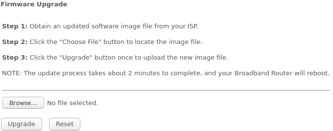
Do not switch off or reboot the device during the update. The process may take several minutes. The device will be automatically rebooted when the update is completed.
The «Remote Access» submenu. Remote access rules configuration
In this section you can configure remote access rules via HTTP/Telnet/ICMP protocols.
Admin → Remote Access
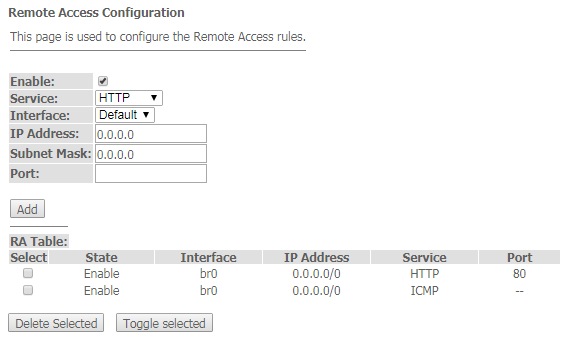
- Enable – enabling the rule to add;
- Service – selection of the protocol used;
- Interface – interface to which the rule applies;
- IP Address – source IP adress;
- Subnet Mask – subnet mask;
- Port – destination port.
To add a rule fill the corresponding fields and click the «Add» button. Added rules are displayed in the «RA Table». To activate/deactivate the selected rule, click the «Toggle selected» button. To delete one rule, select it with a flag in the Select column and click the «Delete Selected» button.
The «Time zone» submenu. System time configuration
In this section you can configure the device system time. Synchronization with accurate online time-servers is available.
Admin → Time zone
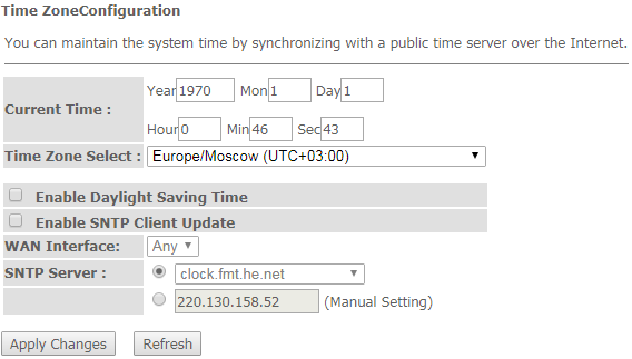
- Current time – current time;
- Time Zone Select – timezone;
- Enable Daylight Saving Time – enable daylight saving time;
- Enable SNTP Client Update – enable time synchronization via SNMP;
- WAN Interface – interface for time update;
- SNTP Server – preferred time server.
To save the changes click the «Apply Changes» button, update the information click «Refresh».
The «Statistics» menu. Traffic flow information for device ports
The «Interface» submenu. Information about timers and errors
This section displays timers/errors for packets for each interface:
Statistics → Interface
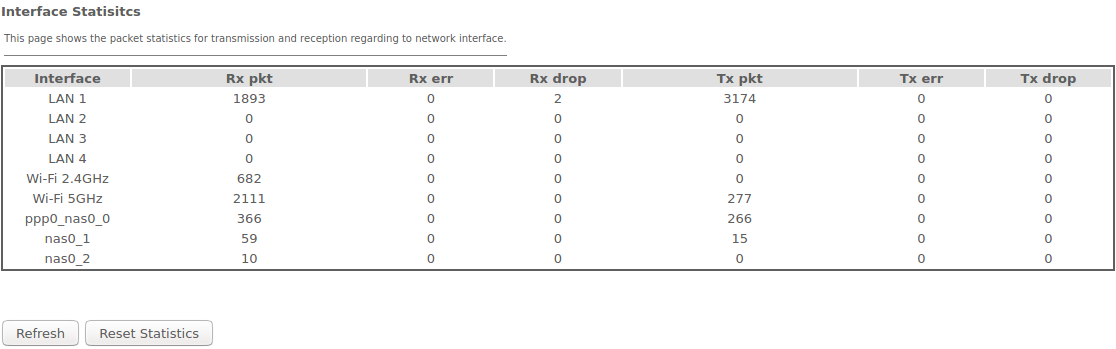
- Interface – interface;
- Rx pkt – packets received;
- RX err – errors on receive;
- Rx drop – rejected on receive;
- Tx pkt – packets sent;
- Tx err – transmission error;
- Tx drop – rejected on transmission.
Th «PON» submenu
This section displays timers for the optical interface:
Statistics → PON
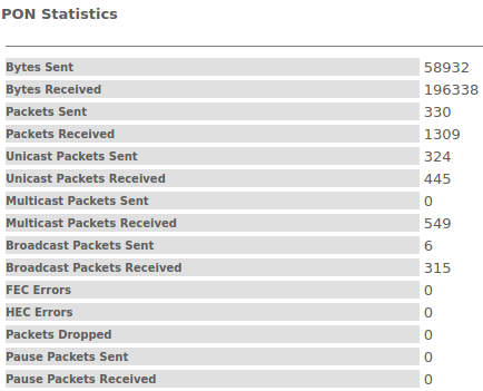
- Bytes Sent – transmitted bytes;
- Bytes Received – received bytes;
- Packets Sent – packets transmitted;
- Packets Received – packets received;
- Unicast Packet Sent – Unicast packets transmitted;
- Unicast Packet Received – Unicast packets received;
- Multicast Packets Sent – Multicast packets transmitted;
- Multicast Packets Received – Multicast packets received;
- Broadcast Packet Sent – Broadcast packets transmitted;
- Broadcast Packet Received – Broadcast packets received;
- FEC Errors – FEC errors
- Packets Dropped – packets rejected.
The «Z-Wave» menu. For NTU-RG-5421G-WZ, NTU-RG-5440G-WZ
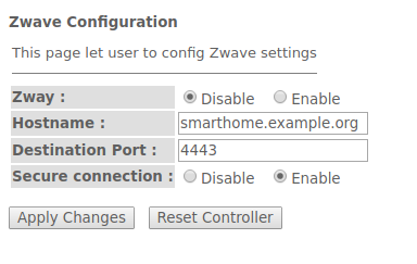
Here you can configure «Smart Home» parameters.
- Zway – enable/disable the «Smart Home» controller;
- Hostname – specify the remote «Smart Home» platform address;
- Destination port – specify the platform port to which the «Smart Home» controller connects;
- Secure connection – set to Enable if a secure channel is used to communicate with the platform;
- Reset controller (clear Zway cache) – when clicking this button, the controller disables; all information on the platform connection, bound sensors and scenarios is removed.
To accept and save the settings, click the «Apply Changes» button.
The list of changes
Document version | Suitable firmware version | Issue date | Revisions |
|---|---|---|---|
| Version 1.7 | 2.3.1 | 03.2021 | Eighth issue |
| Version 1.6 | 2.3.0 | 02.2021 | Seventh issue |
| Version 1.5 | 2.2.0 | 10.2020 | Sixth issue |
| Version 1.4 | 2.1.0 | 07.2020 | Fifth issue |
| Version 1.3 | 1.2.1 | 12.2019 | Fourth issue |
| Version 1.2 | 1.2.0 | 10.2019 | Third issue |
| Version 1.1 | 1.1.0 | 04.2019 | Second issue |
Version 1.0 | 1.0.1 | 11.2018 | First issue |