Wireless bridge WB-3P-PTP5
User manual, firmware version 2.4.1
IP address: http://192.168.1.10
User name: admin
Password: password
Introduction
Annotation
Modern tendencies of telecommunication development necessitate operators to search for the most optimal technologies, allowing one to meet rapidly growing needs of subscribers, while maintaining at the same time consistency of business processes, development flexibility and reducing the costs of various services. Wireless technologies are spinning up more and more, and have paced a huge way for short time from unstable low-speed communication networks of low radius to broadband access networks equitable to speed of wired networks with high criteria to the quality of provided services.
WB-3P-PTP5 is a device designed to organize radio bridges over long distances. The radio bridge involves two such devices. WB-3P-PTP5 has a sealed housing, which allows installing the device mainly in open areas in various climatic conditions.
This operating manual describes the purpose, main technical characteristics, design, safety rules for operating the device, as well as recommendations for installing and configuring the wireless bridge WB-3P-PTP5.
Document conventions
Notes and warnings
Notes contain important information, tips or recommendations on device operation and setup.
Warnings are used to inform the user about harmful situations for the device and the user alike, which could cause malfunction or data loss.
Device description
Purpose
The WB-3P-PTP5 wireless bridge is a next-generation Wi-Fi 6 device designed to provide modern high-speed services.
With support for the IEEE802.11ax standard, the WB-3P-PTP5 wireless bridge provides data transfer rates of up to 2402 Mbps. The use of an offset parabolic antenna makes the WB-3P-PTP5 a universal solution for establishing long-distance radio bridges.
The WB-3P-PTP5 wireless bridge (hereinafter referred to as the "device") supports modern quality of service requirements and enables traffic transmission in priority queues.
WB-3P-PTP5 can operate in a wide range of operating temperatures and high humidity.
Device specification
Interfaces:
1 port of Ethernet 10/100/1000BASE-T (RJ-45);
Wi-Fi 5 GHz IEEE 802.11a/n/ac/ax.
The power is supplied via 24 V PoE injector from 220 V.
Using a PoE injector with a voltage different from 24 V will damage the device.
Functions:
WLAN capabilities:
support for IEEE 802.11a/n/ac/ax;
data aggregation, including A-MPDU (Tx/Rx) and А-MSDU (Rx);
WMM-based packet priorities and planning;
dynamic frequency selection (DFS);
- access point (AP-PTP/AP-PMP) mode;
- client (STA) mode;
- auto-distance detection;
- support for hidden SSID;
MAC ACL;
third-party access points detection;
support for APSD;
- channel list limitation;
spectrum analyzer;
- support for fixed center frequency;
- support for TDD;
antenna alignment.
Network features:
automatic speed negotiation and duplex mode;
support for VLAN (Access, Trunk, General);
Management VLAN;
DHCP client;
- VLAN Mapping;
- Loopback Detection;
- MVR;
NTP;
Syslog;
DHCP snooping;
IGMP snooping (limit on the maximum number of groups);
limiting the number of MAC addresses learned (MAC-learning);
BPDU;
IPv6;
LLDP;
Ping Watchdog.
QoS functions:
bandwidth limiting;
configuring WMM parameters for the radio interface;
priority by 802.1p, DSCP and VLAN ID;
- traffic priority based on MAC/IP address.
Security:
centralized authorization via RADIUS server (802.1X WPA/WPA2/WPA3 Enterprise);
WPA/WPA2/WPA3/OWE encryption;
- authorization via RADIUS server when logging.
Figure 1 shows WB-3P-PTP5 application diagram.
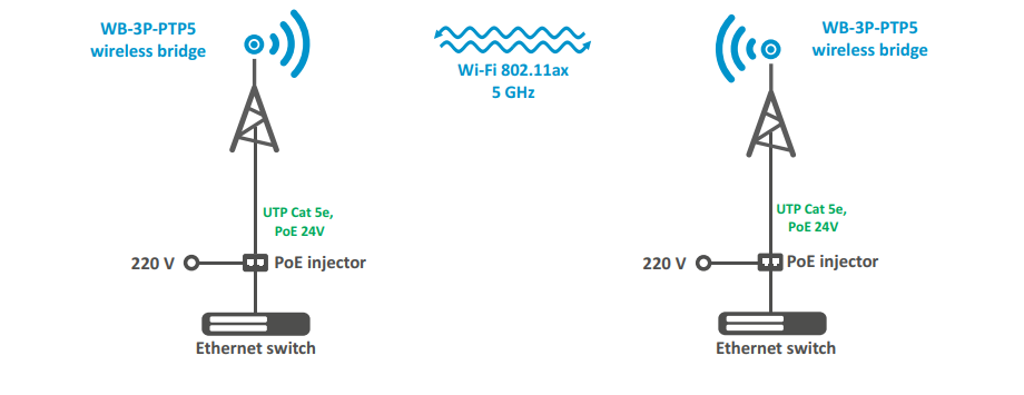
Figure 1 — WB-3P-PTP5 application diagram
Technical parameters
The main technical parameters of the device are given in Table 1.
Table 1 – Main specifications
| Ethernet interface parameters | |
| Number of ports | 1 |
| Electrical connector | RJ-45 |
| Data rate | 10/100/1000 Mbps, auto-negotiation |
| Standards | BASE-T |
| Wireless interface parameters | |
| Standards | 802.11a/n/ac/ax |
| Frequency range | 5150–5975 MHz |
| Modulation | BPSK, QPSK, 16QAM, 64QAM, 256QAM, 1024QAM |
| Operating channels1 | 802.11a/n/ac/ax: 32–193 (5150–5975MHz) |
| Data rate2 | 802.11ax: 2402 Mbps |
| Maximum number of concurrent sessions | 5 GHz: 64 |
| Maximum output power of the transmitter1 | 5 GHz: 27 dBm |
| Receiver sensitivity | 5 GHz: up to -96 dBm |
| Security | WPA/WPA2/WPA3/OWE |
| Antenna parameters | |
| Gain | 9 dBi |
| Polarization | linear, H/V |
| SWR | no more than 2 |
| Beam width (horizontal) | 65° |
| Beam width (vertical) | 65° |
| Management | |
| Remote management | web interface, CLI, Telnet, SSH, SNMP, NETCONF |
| Access restriction | by password, authentication via RADIUS server |
| General parameters | |
| Flash | 128 MB SPI-NAND Flash |
| RAM | 256 MB DDR3 RAM |
| Power supply | Passive PoE 24 V |
| Power consumption | no more than 11.5 W |
| Ingress protection | IP67 |
| Operating temperature range | from -45 to +65 °С |
| Relative humidity at 25 °C | up to 95 % |
| Dimensions (W × H × D) | 120 × 110 × 89 mm 120 × 110 × 144 mm (with cable gland) |
| Weight | 0.31 kg |
| Service life | no less than 15 years |
1 The number of channels and the value of the maximum output power will vary according to the rules of radio frequency regulation in your country.
2 The maximum wireless data rate is defined according to IEEE 802.11 standards. The real bandwidth can be different. Conditions of the network, environment, the amount of traffic, building materials and constructions and network service data can decrease the real bandwidth. The environment can influence the network coverage range.
Technical parameters of offset parabolic antenna
The main technical parameters of the offset parabolic antenna are given in Table 2.
Table 2 – Main specifications of offset parabolic antenna
| Parameters | Antenna 450 × 495 mm |
| Gain at 2.4 GHz | 25 dBi |
| Offset angle | 24° |
| Polarization | linear, H/V |
| Radiation angle | 7° |
| Focal distance | 270 mm |
| Wind load | 130 km/h — operating 185 km/h — limit |
| Reflector dimensions | 450 × 495 mm |
| Dimensions (W × H × D) | 450 × 570 × 492 mm |
| Weight | 1.6 kg |
| Material | steel |
Radiation patterns
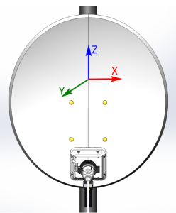
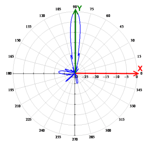
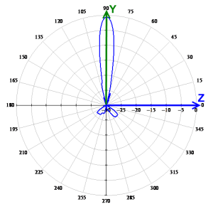
The figures below show the radiation patterns of the device.
WB-3P-PTP5 radiation patterns | |
Measurement position
| |
AZIMUTH (XY)
| ELEVATION (YZ)
|
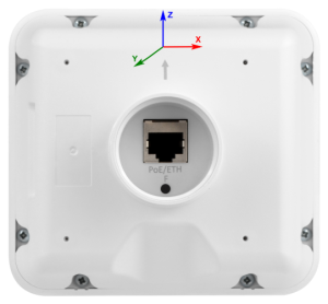
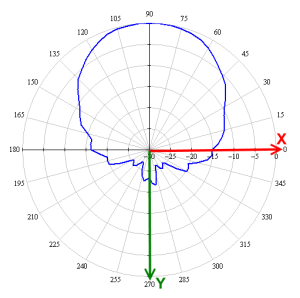
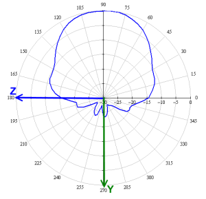
WB-3P-PTP5 radiation patterns | |
Measurement position
| |
AZIMUTH (XY)
| ELEVATION (YZ)
|
Design
The WB-3P-PTP5 device has a plastic housing in industrial design. The main panel layout of WB-3P-PTP5 is shown in Figure 2.

Figure 2 — WB-3P-PTP5 main panel layout
The rear panel of WB-3P-PTP5 is shown in Figure 3.
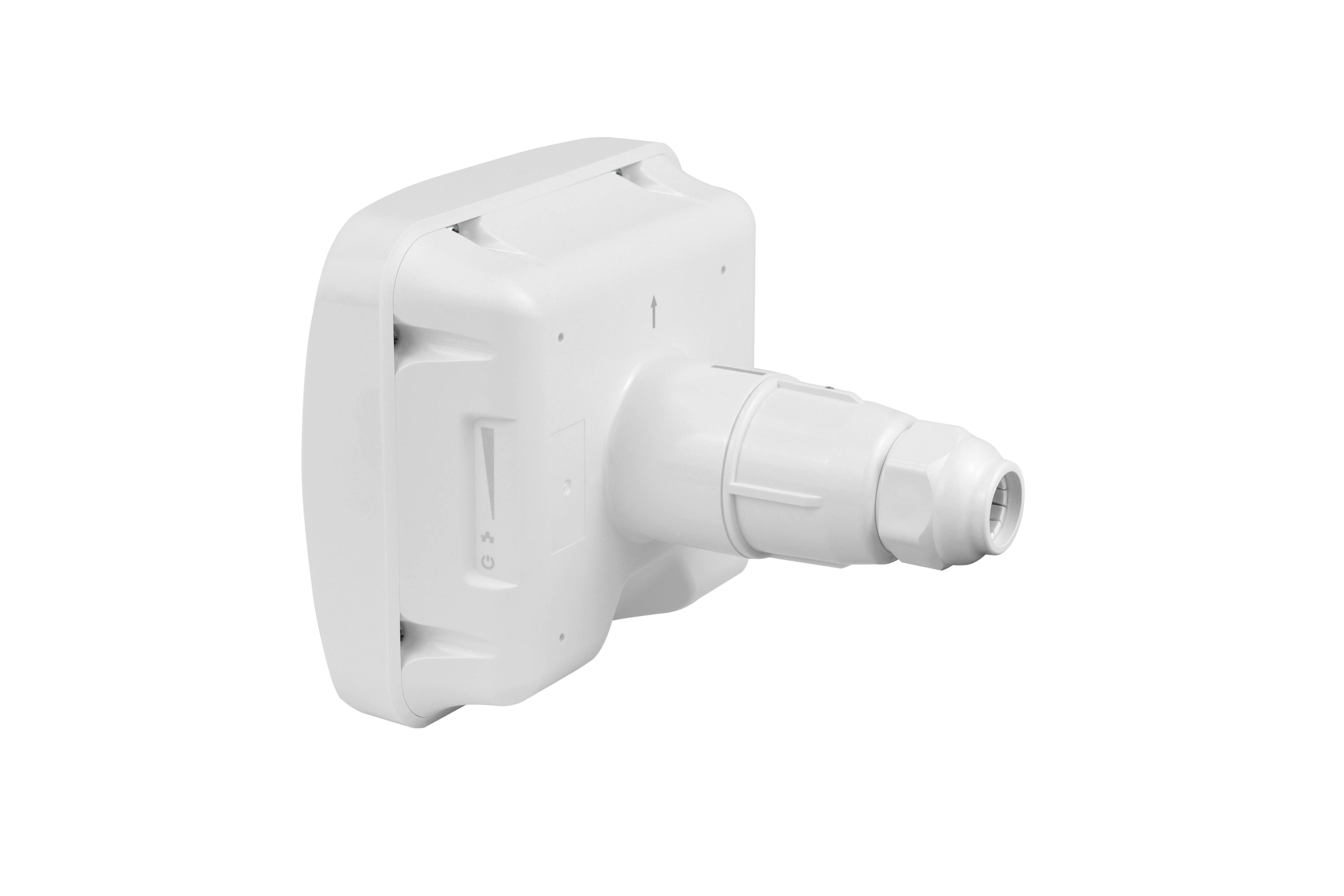 Figure 3 — WB-3P-PTP5 rear panel
On the rear panel of WB-3P-PTP5 under the cable gland, there is a 10/100/1000BASE-T Ethernet port (RJ-45 connector) for connecting to the network and PoE power supply, as well as a factory reset button "F" (see Figure 4).
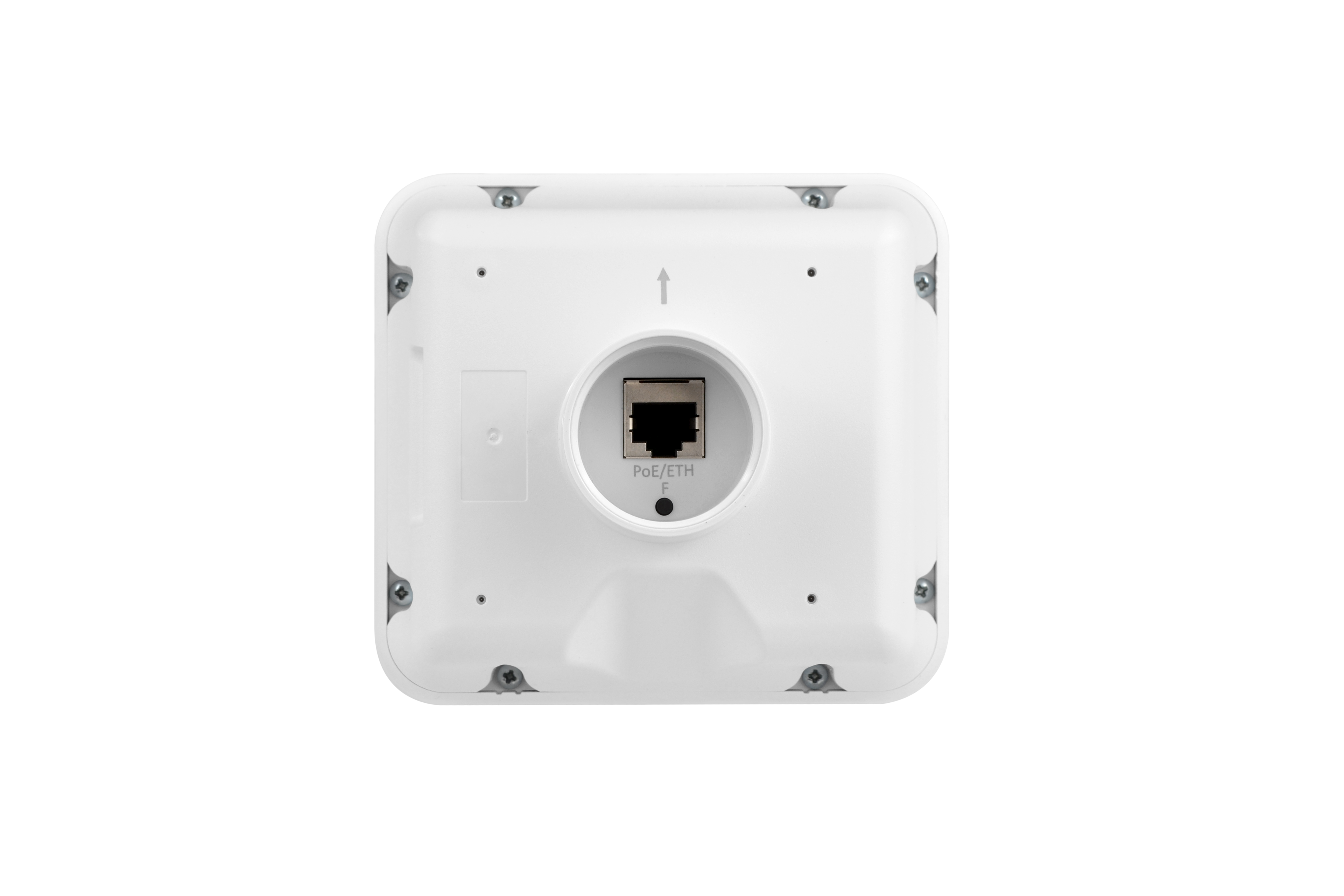
Figure 4 — RJ-45 and factory reset button "F"
Light indication
The layout of the WB-3P-PTP5 indicator panel is shown in Figure 5.
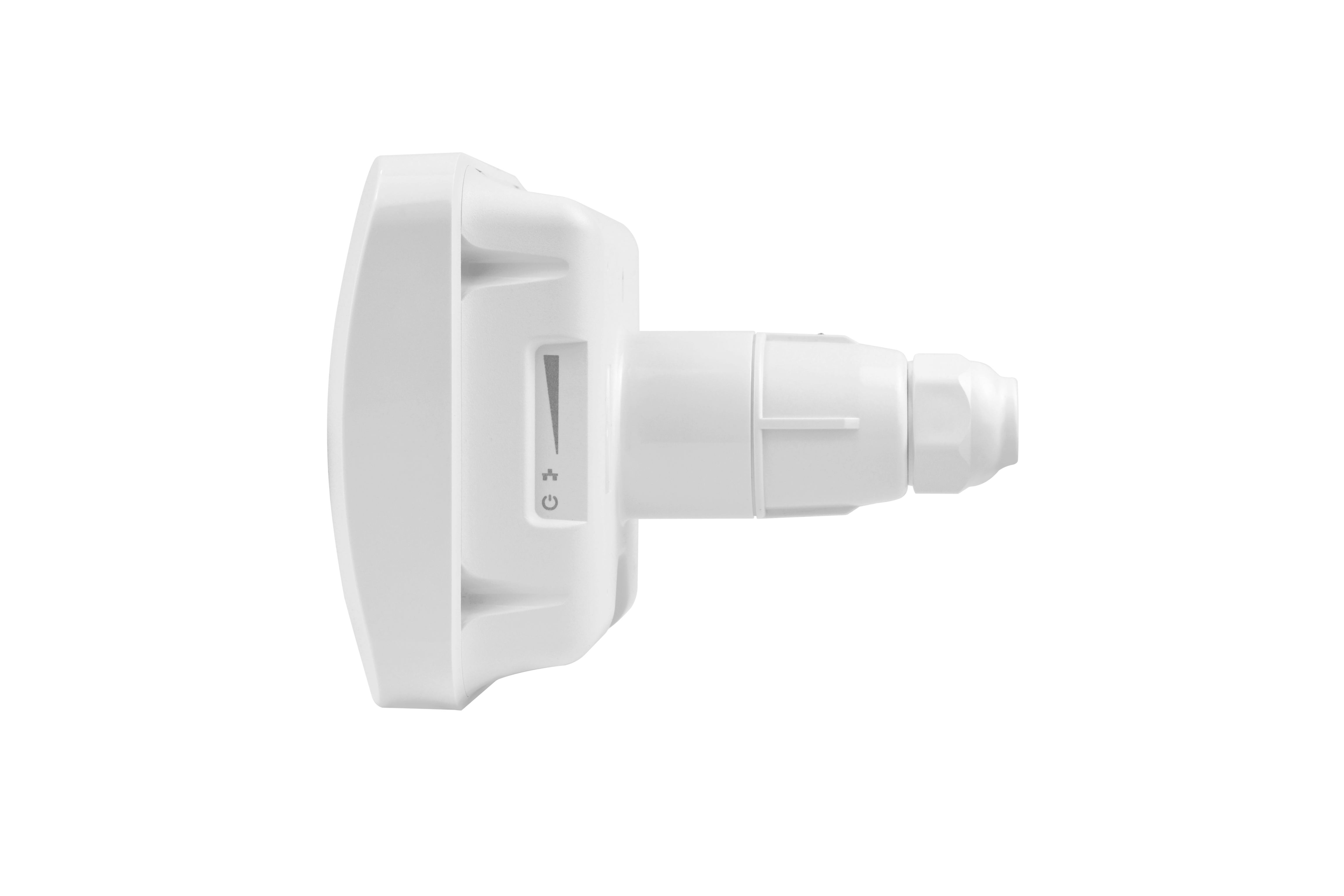
Figure 5 — WB-3P-PTP5 indicator panel
The current state of the device is displayed using indicators located on the side panel. The list of indicators and their states are given in Table 3.
Table 3 — Light indication of device status
| LED | LED status | Description | |
|---|---|---|---|
 | WLAN — Received Signal Strength Indicators (RSSI) | solid | device is connected, the signal level from the remote device is greater than -60 dBm |
| solid | device is connected, the signal level from the remote device is greater than -70 dBm | |
| solid | device is connected, the signal level from the remote device is greater than -80 dBm | |
| solid | device is connected, the signal level from the remote device is greater than -100 dBm | |
| none of indicators is on | no connection between devices | ||
| LAN — Ethernet port indicator | solid | channel between WB-3P-PTP5 Ethernet interface and connected device is active |
| flashing | process of packet data transfer between WB-3P-PTP5 Ethernet interface and connected device | ||
| Power — power and device status indicator | solid | power connected, normal operation |
| flashing | device did not receive an address via DHCP | ||
| blinks frequently for 3 seconds, then stays on continuously | reboot/factory reset |





Restore the default configuration
There are two ways to reset your device to factory settings.
- Using the "F" button on the device. When the device is loaded, press and hold the "F" button (about 10–15 seconds) on the device rear panel, until all WLAN indicators start flashing.
- Using the PoE injector, that is included into the supply package. When the device is loaded, press and hold the "RST" button on the injector (for about 10–15 seconds) until all WLAN indicators start flashing.
The device will be rebooted automatically. DHCP client will be launched by default. If the address is not obtained via DHCP, the device will have the factory IP address — 192.168.1.10, and the following netmask — 255.255.255.0; login/password for web interface — admin/password.
Supply package
The basic supply package of WB-3P-PTP5 includes:
- WB-3P-PTP5 wireless bridge;
- Cable gland;
- Power injector Passive PoE 24 V;
- Power cable;
- Patch cord RJ-45, 5е cat., 1.5m;
- User manual on a CD (optional);
- Technical passport.
Rules and recommendations for device installation
This section defines safety rules, installation recommendations, setup procedure and starting procedure of the device.
Safety rules
- Do not open the device housing. There are no user-serviceable parts inside.
- Do not install this device during a thunderstorm. There is a risk of lightning strike.
- The voltage, current and frequency requirements specified in this manual should be observed.
- Before connecting measuring instruments and a computer to the device, they should be grounded. The potential difference between the equipment and measuring instrument casings should not exceed 1 V.
- Before turning on the device, ensure that the cables are intact and securely attached to the connectors.
- Do not install the device near heat sources or in rooms with temperatures below -45°C or above 65°C.
- When mounting the device on high-rise structures, comply with established standards and requirements for working at height.
- The device should be operated by specially trained engineering and technical personnel.
- Connect only suitable auxiliary equipment to the device.
Installation recommendations
- The device can be installed on a pole/post, wall or in an offset parabolic antenna holder. The installation height should be at least 1 meter from the underlying surface, the installation distance should be no more than 5 meters from the edge of the surface. If it is impossible to comply with the latter condition, increase the suspension height.
- Before installing the device and turning it on, check the device for visible mechanical defects. If defects are observed, stop the device installation, fill in the corresponding act and contact the supplier.
- Estimate the signal level at the receiving point using the formulas for calculating signal propagation in free space.
- To ensure the best signal level, place the device on a post/pole so that its antenna is pointed as much as possible at the antenna of the remote device. In this case, direct visibility should be ensured between devices, and the Fresnel zone should be clear of obstacles. The highest signal level can be obtained by adjusting the antenna using RSSI indicators, web interface (more details in the "Antenna Align" submenu) or CLI command.
- After alignment, make sure that the signal from the remote device is as close as possible to the calculated value and is not lower than the permissible level of -65 ÷ -70 dBm.
- If the signal exceeds -40 dBm, it is necessary to reduce the transmitter power on the remote device.
- When installing offset parabolic antennas, take into account the antenna offset angle: to have the direction of maximum radiation parallel to the ground, the tilt angle of the parabolic antenna should be equal to the offset angle.
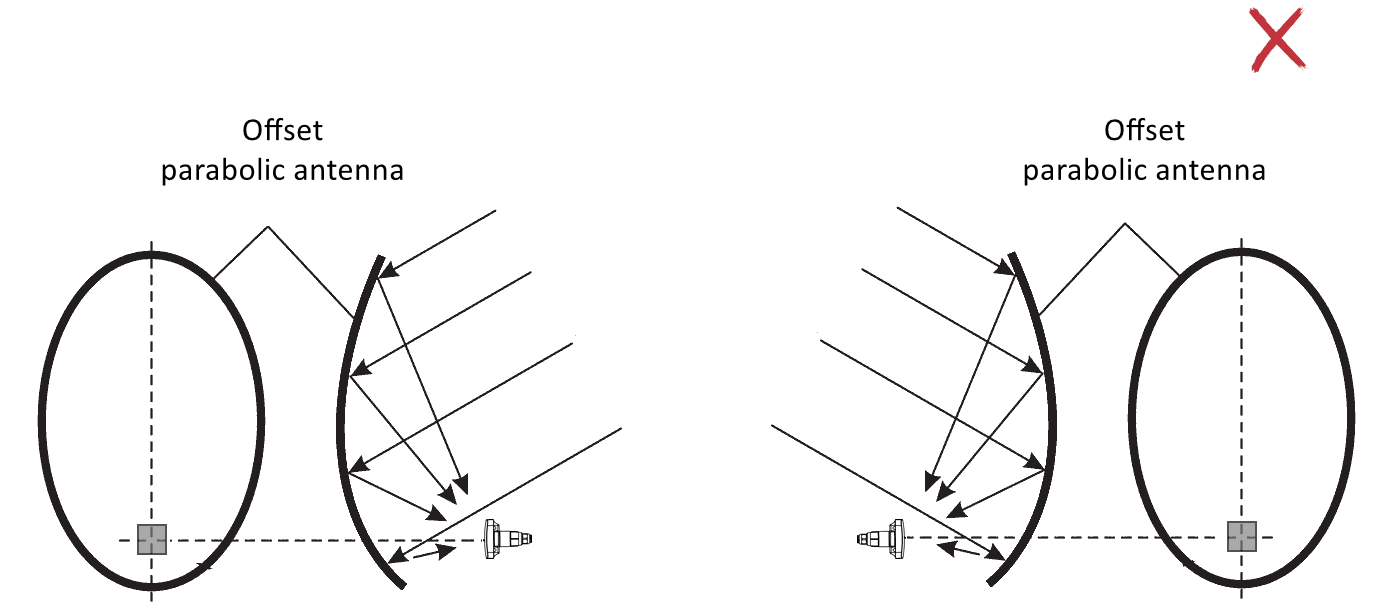
Figure 6 — Incorrect installation of offset parabolic antennas
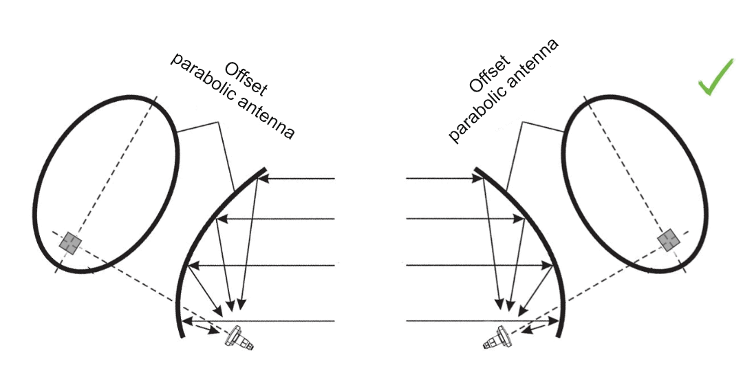
Figure 7 — Correct installation of offset parabolic antennas at the same suspension height
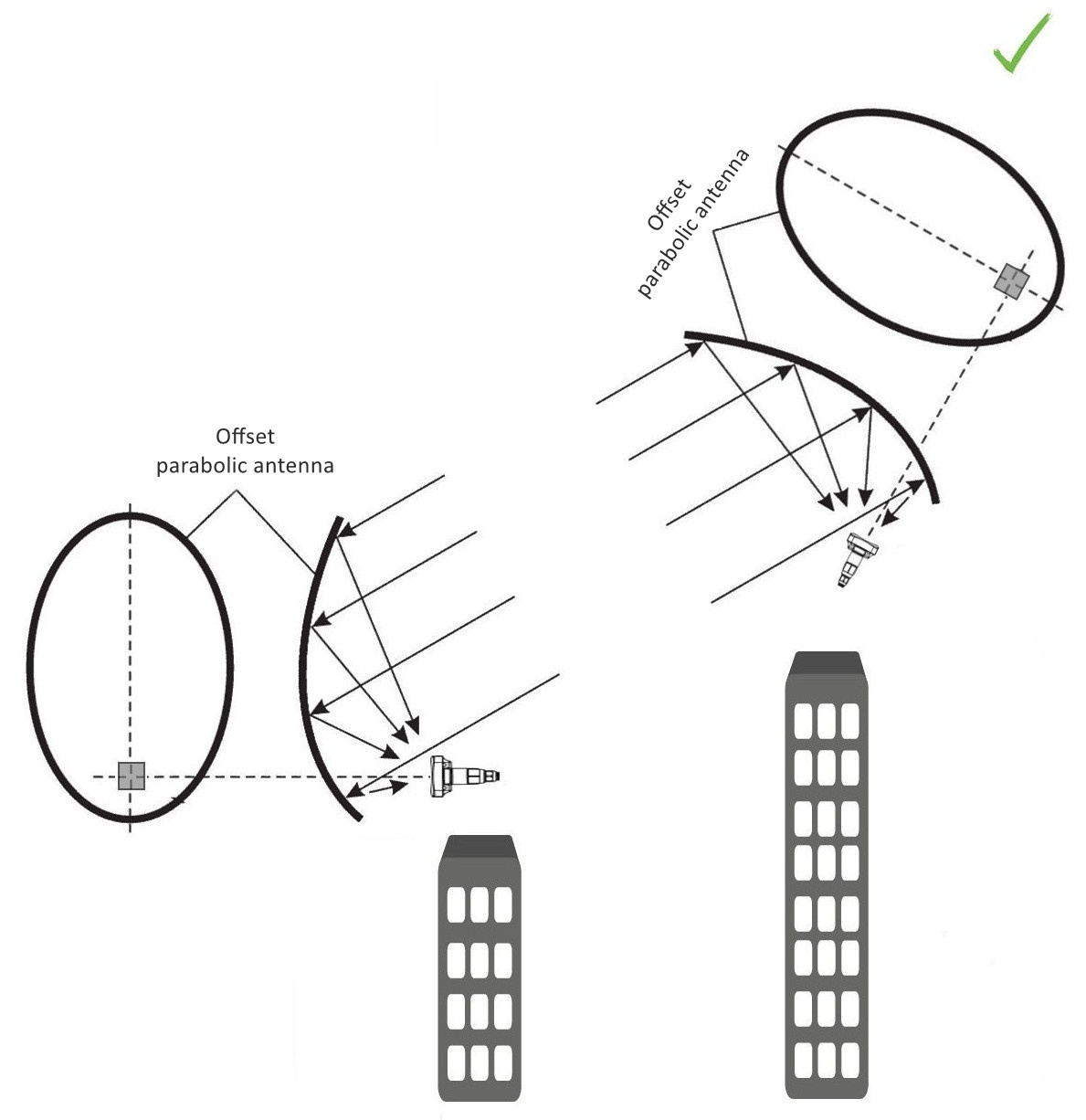
Figure 8 — Correct installation of offset parabolic antennas at different suspension heights
Recommendations for lightning protection
- Grounding should be done with an insulated multi-core wire. The grounding device and the cross-section of the grounding wire should comply with the requirements of the Electrical Installation Code.
- The first outdoor lightning protection should be installed as close as possible to the device, connecting them with a short outdoor FTP cable with shielded connectors.
- The second outdoor lightning protection should be installed as close as possible to the PoE injector, connecting them with a short outdoor FTP cable with shielded connectors.
- The lightning protections are connected to each other with an outdoor FTP cable up to 100 m long.
- The PoE injector should be connected to a 220V grounded electrical outlet.
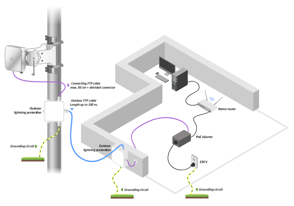
Figure 9 — Device wiring diagram for lightning protection
Device preparation
1. Remove the device from the package.
2. Connect the Ethernet cable to the PoE/ETH port.
Figure 10 — RJ-45 connector and "F" button
Device connection
1. Connect the Ethernet cable from WB-3P-PTP5 to the PoE port of the injector.
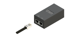
2. Connect the Ethernet cable of your network to the LAN port of the PoE injector.
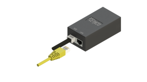
3. Connect the PoE injector to a 220V outlet using the power cord. After powering on, WB-3P-PTP5 will boot up within a minute.
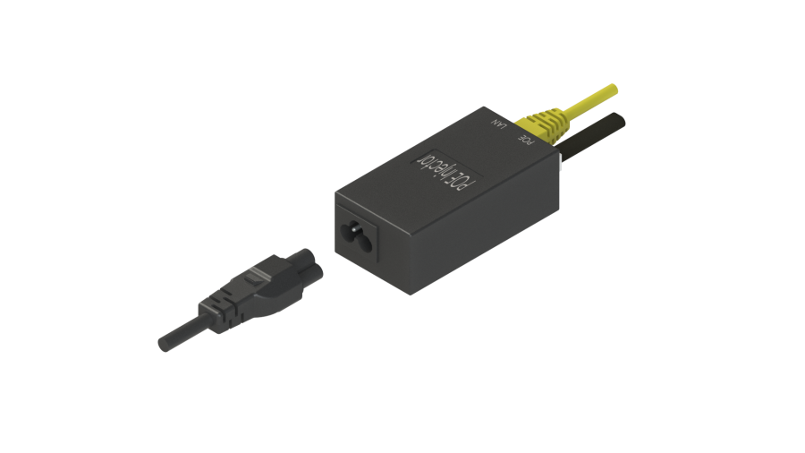
4. Connect to the WB-3P-PTP5 web configurator using a browser, following the instructions in the section Device management via web interface.
5. If this is the first device start-up, then go to the section Preliminary setup.
Preliminary setup
Before installation, perform preliminary setup of the device.
- Make sure the power is connected.
- Follow the algorithm from the section Example of the device setup.
Make sure that a wireless connection is established between the devices: the signal strength indicators should light solid. The possible indicator states are described in the section Light indication.
Device installation
The WB-3P-PTP5 wireless bridge has three mounting options: on a pole/post, on a wall, and as a part of an offset parabolic antenna.
Device installation on a pole/post/wall
- Connect the device to the network and perform preliminary setup following the instructions in the section Preliminary setup. Then disconnect the device from the network and proceed with installation.
- Remove the bracket, bag with fasteners, and clamps from the package.
- Fix the bracket on the pole using the Ø60–80 clamp from the package. The final tightening of the clamp Ø60–80 is performed in step Alignment of devices mounted on a pole/post/wall. Fix the screw with the chain onto the bracket, then put the clamp Ø32–50 onto the tightening slats of the bracket. Follow the safety instructions. See rules and recommendations for device installation.
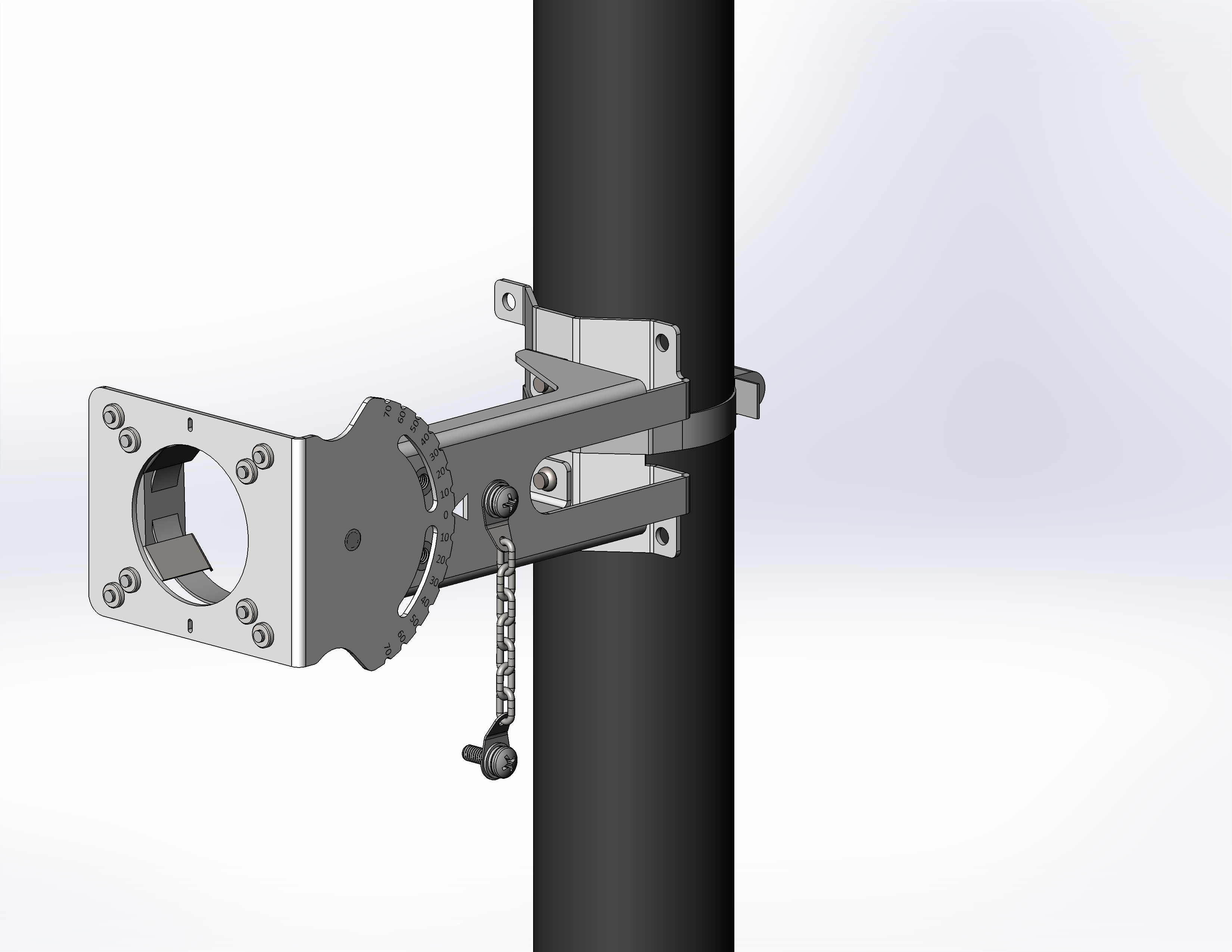
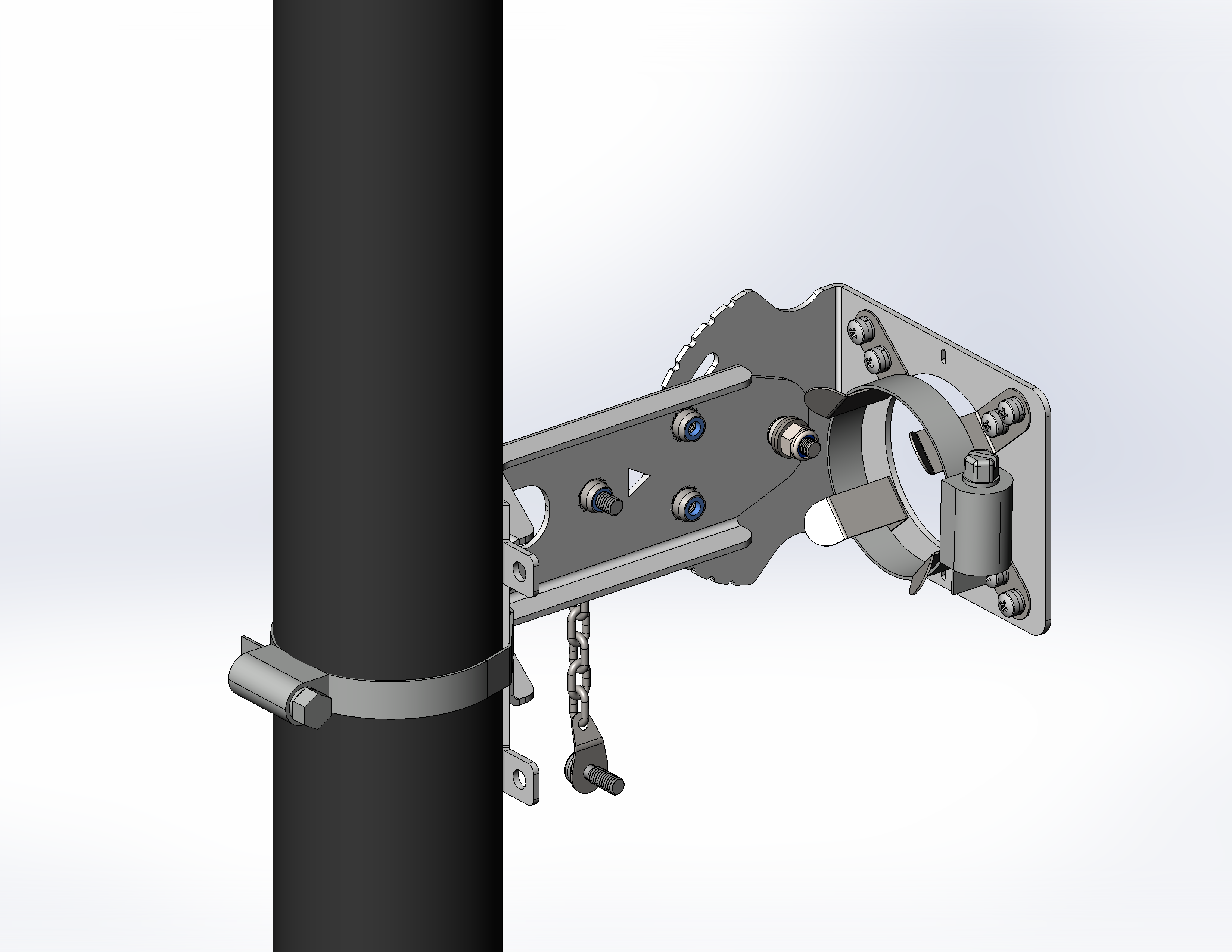
Figure 11 — Mounting the bracket on the pole
4. Disassemble the cable gland — unscrew the sealing nut and remove the split gland from inside.
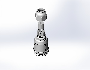
Figure 12 — Dismantling the cable gland
5. Pass the cable through the bracket and the cable gland as shown in Figure 13.
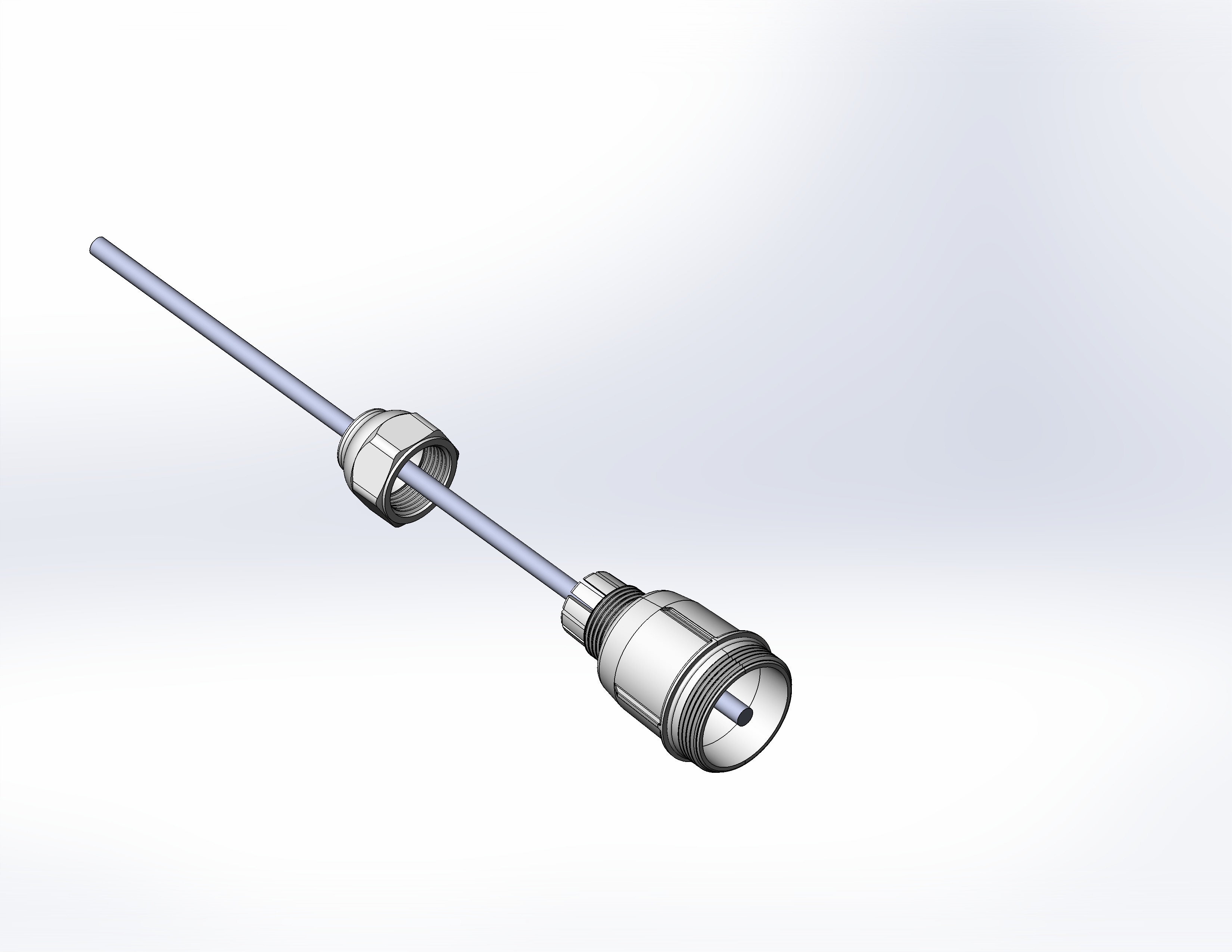
Figure 13 — Cable pulling through the cable gland
6. When installing the device with a deviation of ±10 degrees, refer to Figure 14 (a). When installing the device with a deviation of ±10–70 degrees, refer to Figure 14 (b).
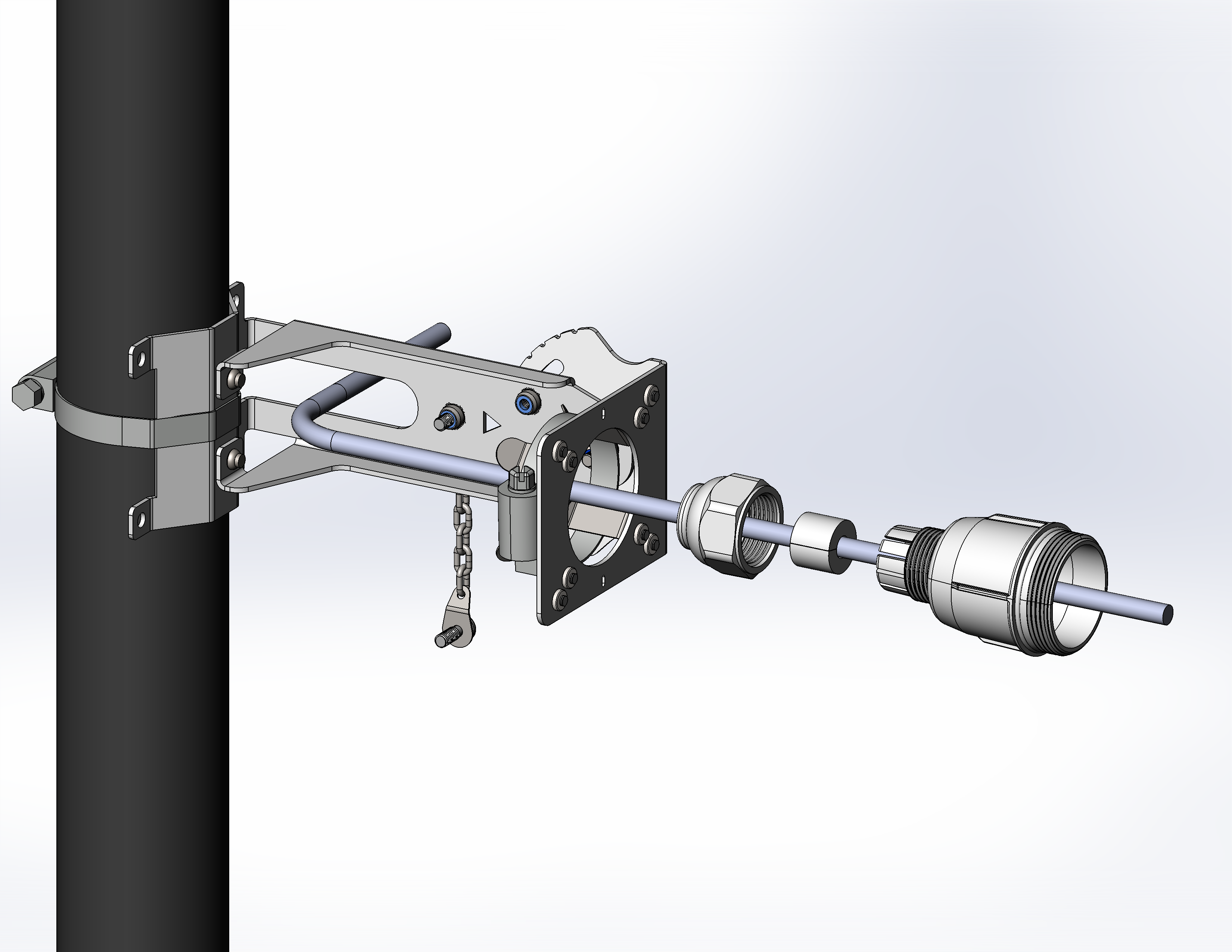
Figure 14 (a)
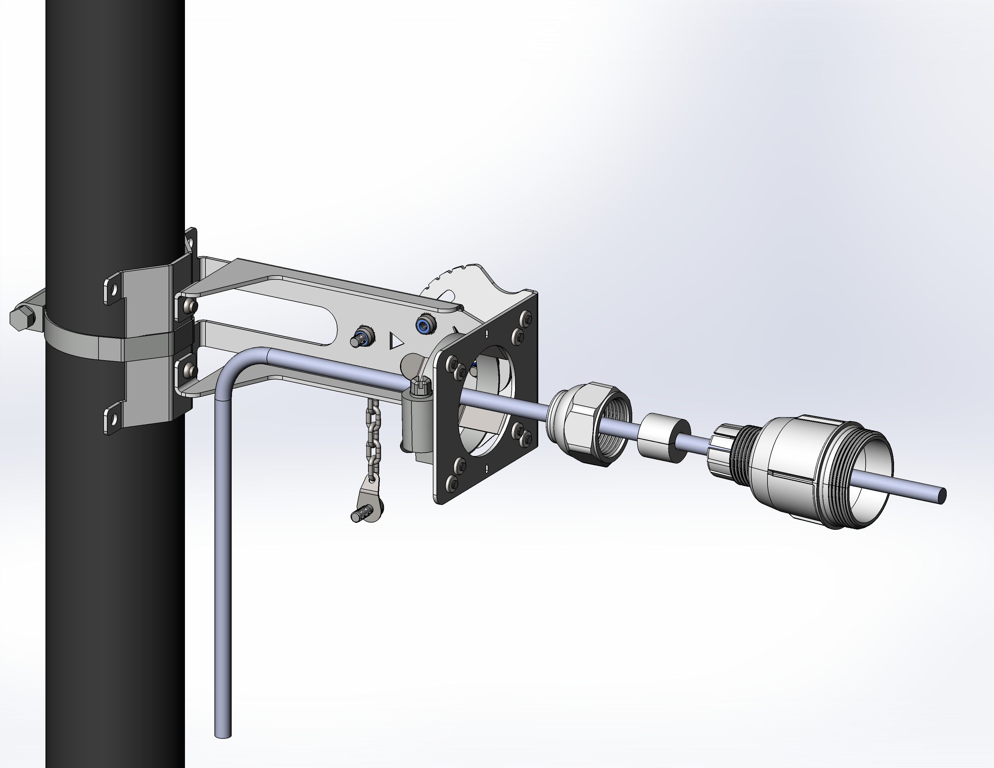
Figure 14 (b)
7. Crimp the RJ-45 connector onto the cable and connect it to the mating part on the device housing.
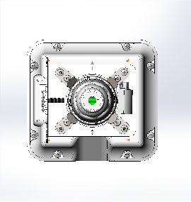
Figure 15 — RJ-45 connector on the device housing
8. Securely tighten the gland body, place the split gland on the cable and insert it into the gland body. Tighten the sealing nut until it stops.
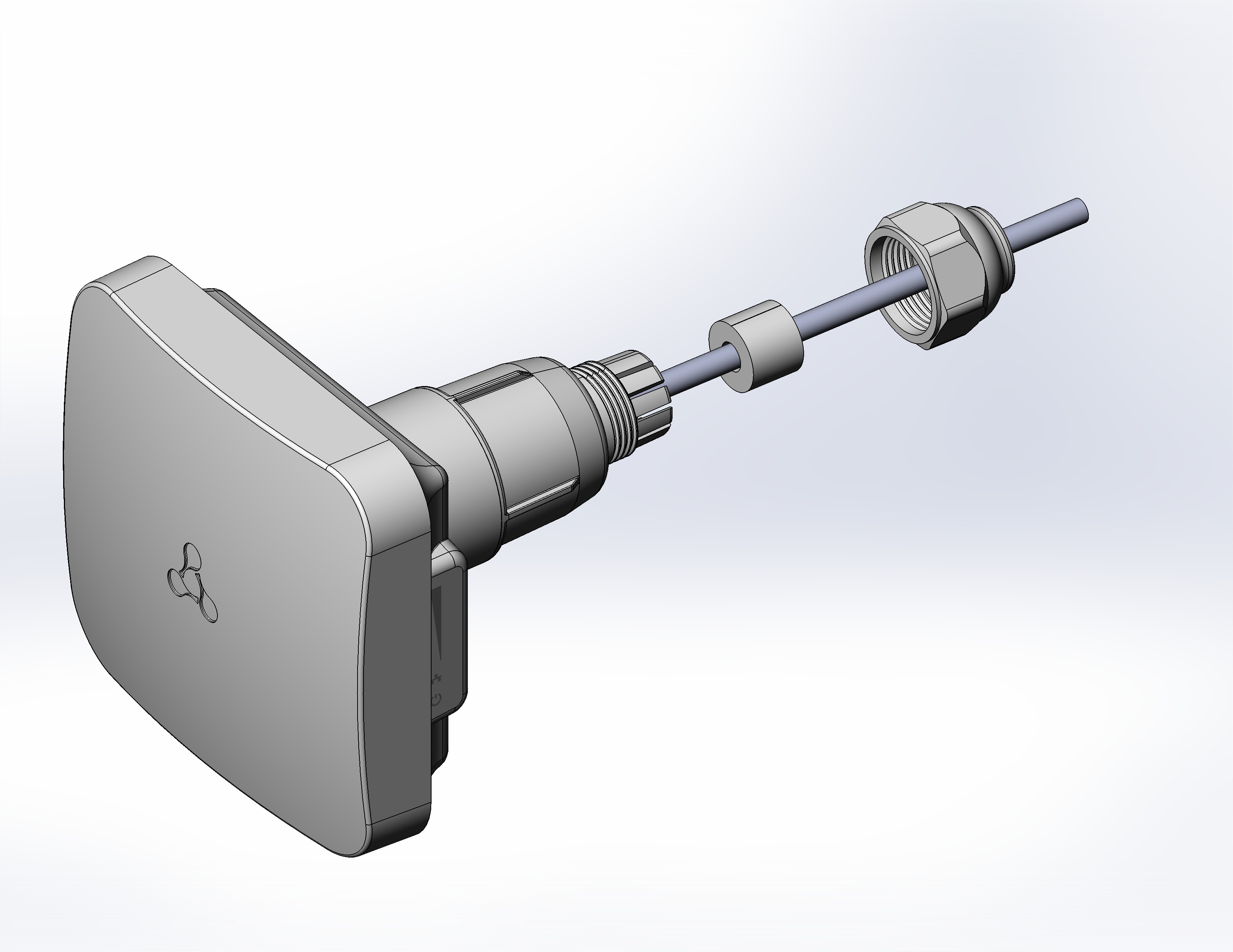
Figure 16 — Installation of the cable gland
Incorrect installation of the cable gland can compromise the device sealing.
9. Insert the device into the bracket slats. Adjust the device by aligning the arrow on the device housing with the hole in the bracket, and tighten the clamp Ø32–50.
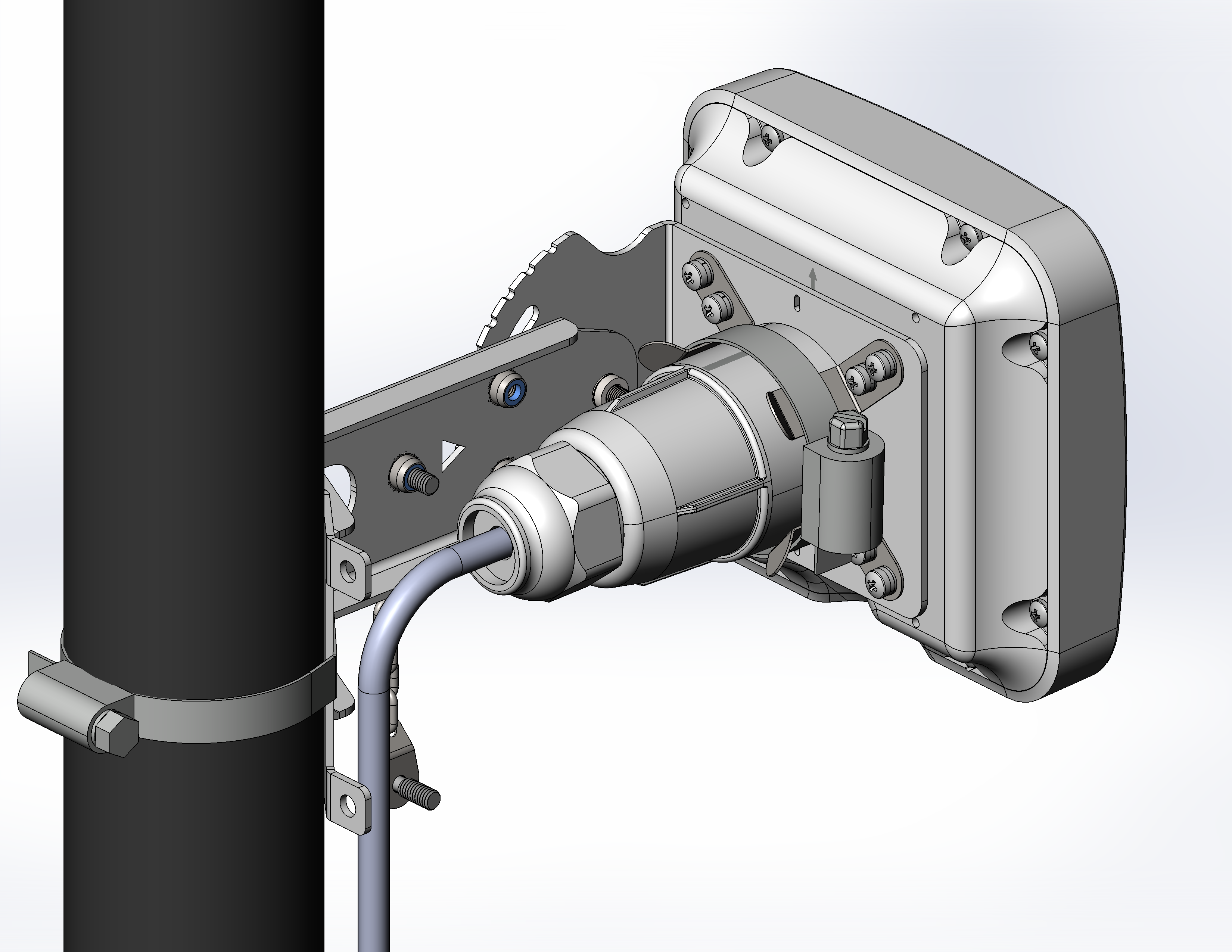
Figure 17 — Installing the device into the bracket
10. After installation, rotate the device to the required angle, using the scale located on the bracket as a reference. The tilt angle can be adjusted from -70 to 70 degrees.
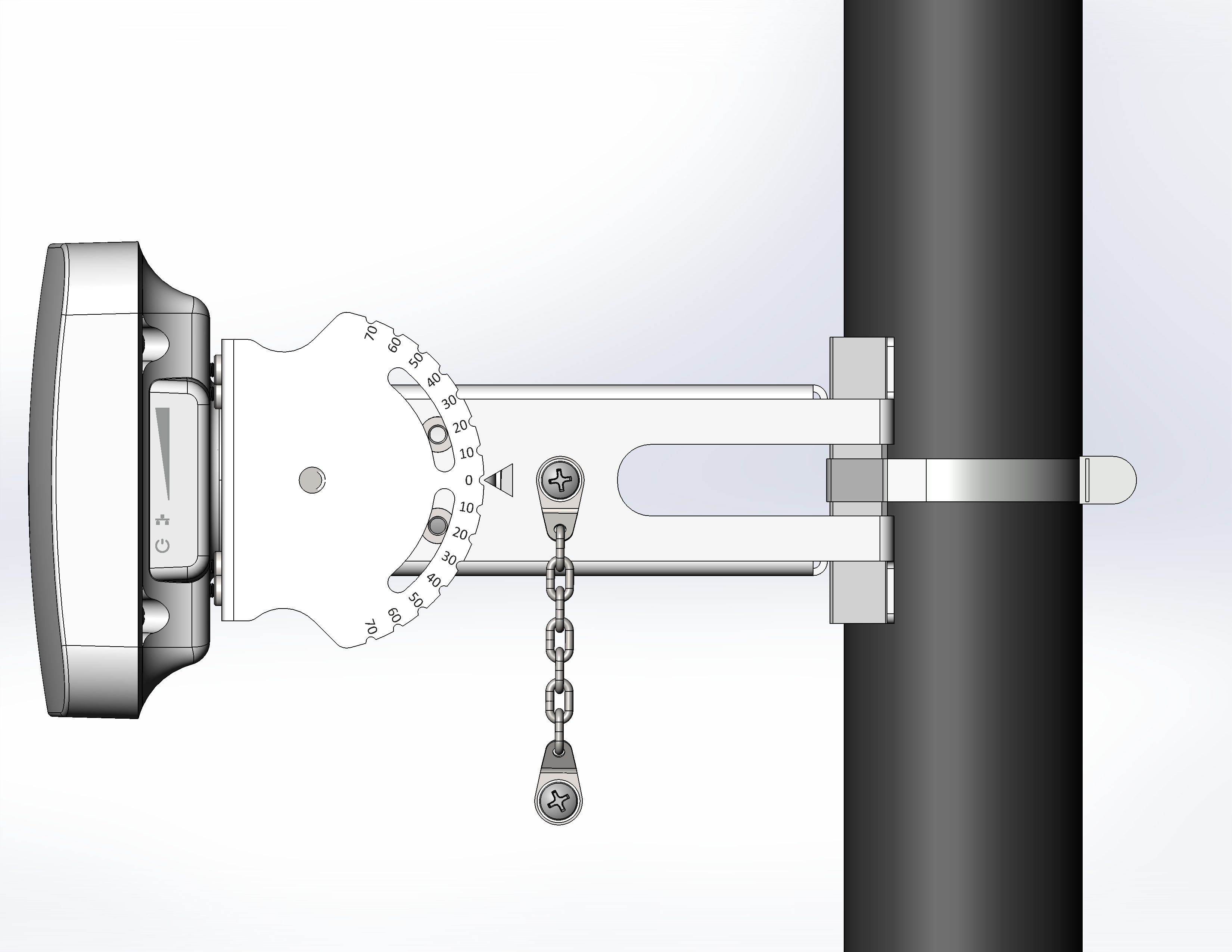
Figure 18 — Setting the required tilt angle
11. It is possible to install the bracket on the wall. When installing on a wall, use screws, self-tapping screws 4×40 mm, and, if necessary, 6×40 mm dowels (Figure 19).
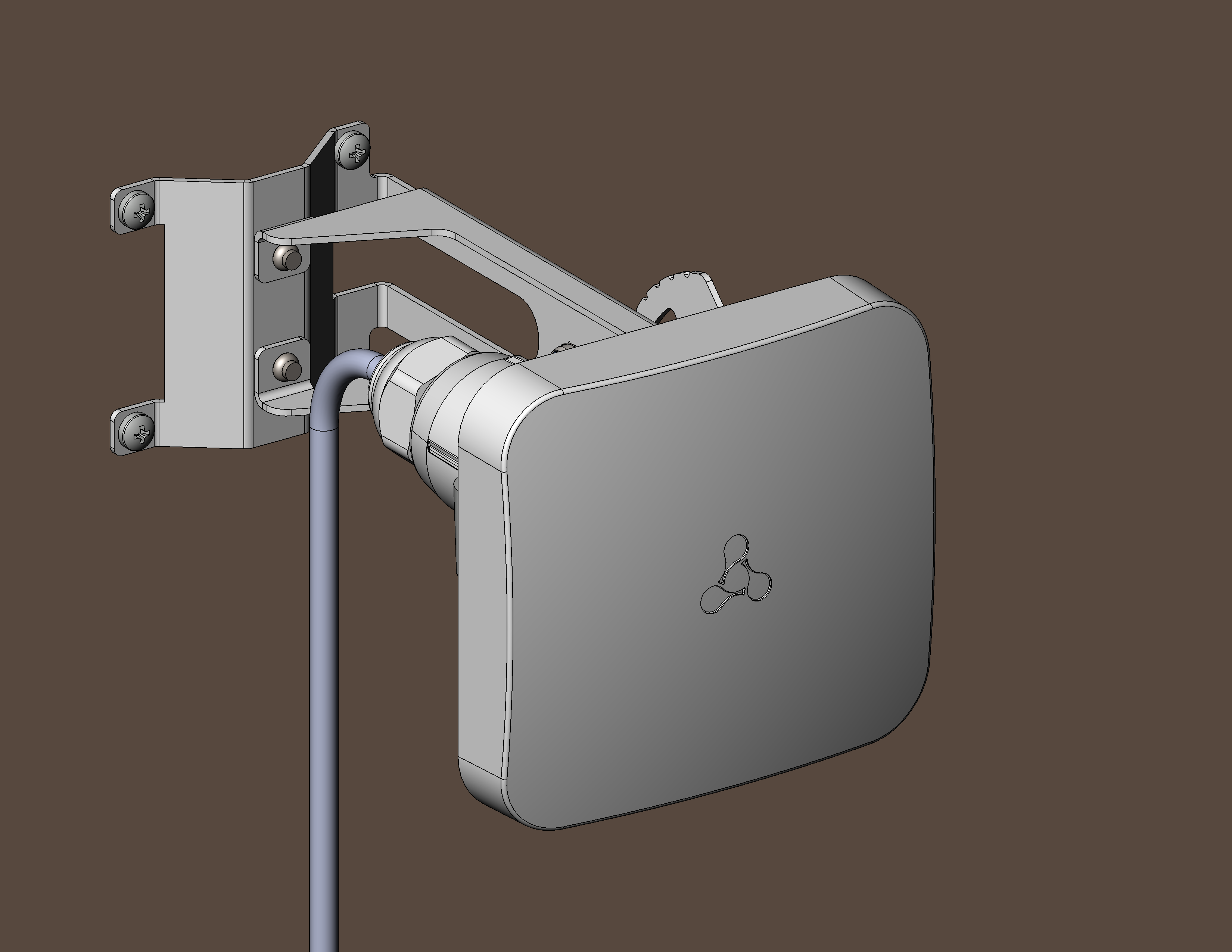
Figure 19 — Mounting the device on the wall
12. Connect the device to the network following the algorithms in the Device connection sections. Then proceed to device alignment.
To prevent the device failure, it is recommended to use lightning protection.
Installation of the device as part of an offset parabolic antenna
Supply package:
- WB-3P-PTP5 basic supply package;
- Offset parabolic antenna with mounting kit.
To install the device as part of an offset parabolic antenna, follow these steps:
1. Connect the device to the network and perform preliminary setup following the instructions in the Preliminary setup section. Then disconnect the device from the network and proceed with installation.
2. Assemble the device holder by inserting the top part axis into the bottom part slots. Install the M4×20 screw with a nut on the right side of the holder.
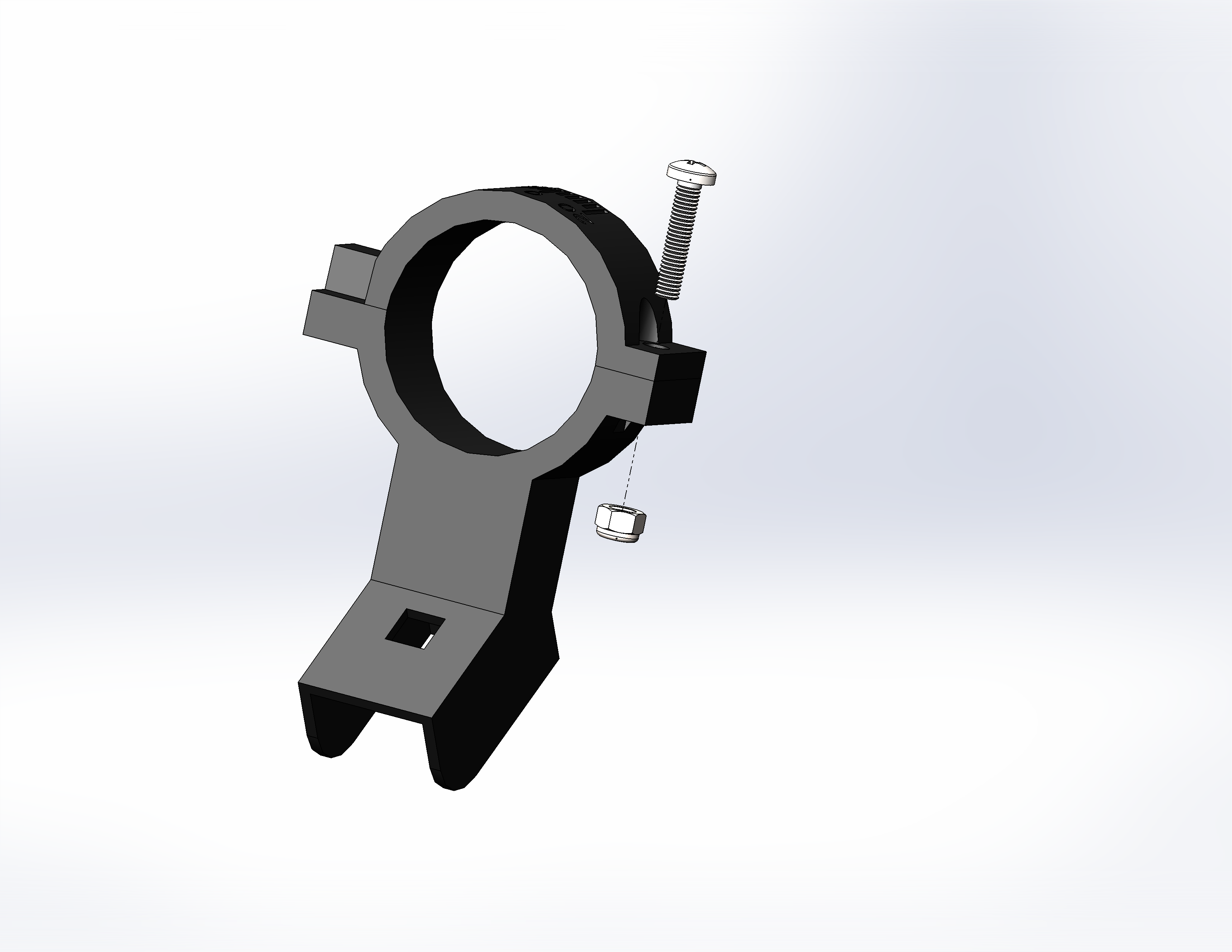
Figure 20 — Assembling the device holder
3. Attach the holder and the movable part of the bracket to the arc using M6×30 bolts, bracket and nuts from the mounting kit. Install the plug on the upper end of the arc.
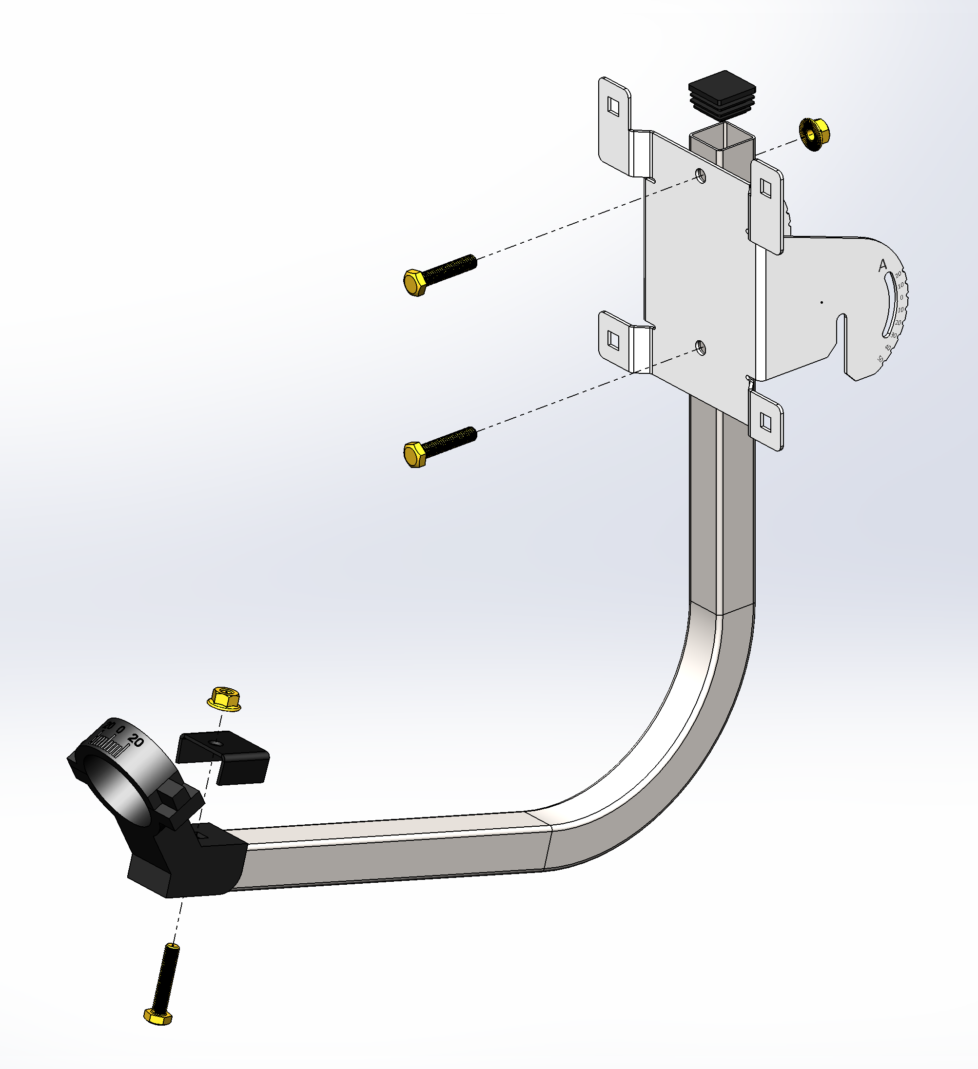
Figure 21 — Fastening the holder and the movable part of the bracket on the arc
4. Connect the movable part of the bracket and the antenna reflector using M6×12 bolts and nuts.
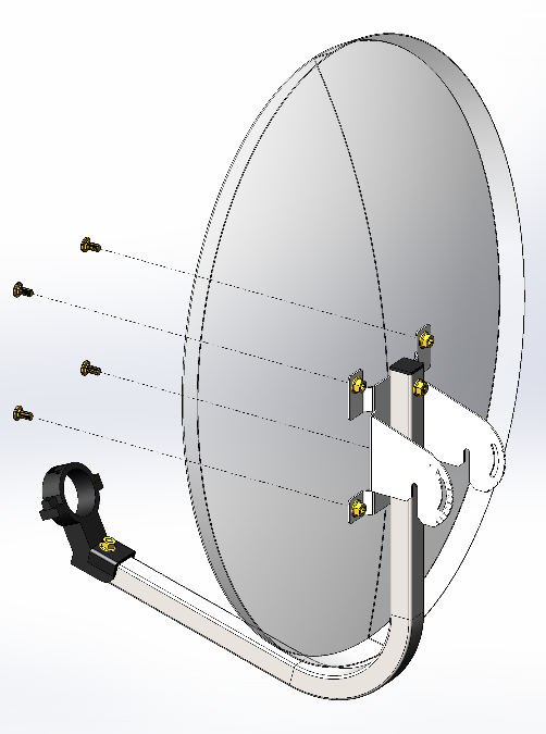
Figure 22 — Mounting the antenna reflector on the movable part of the bracket
5. Disassemble the cable gland — unscrew the sealing nut and remove the split gland from inside.
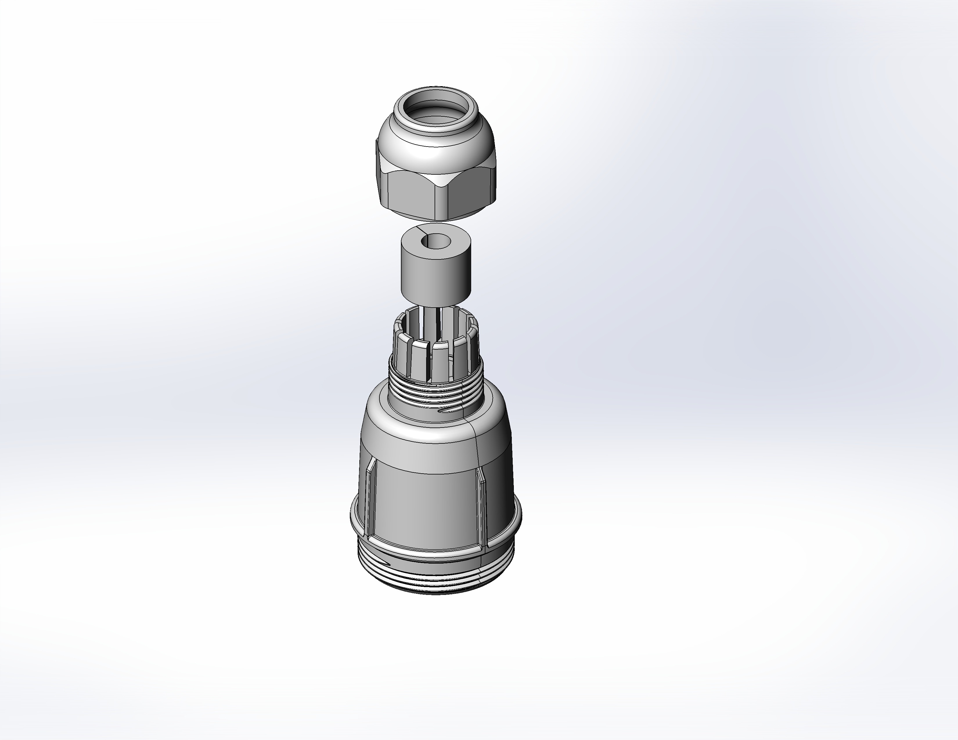
Figure 23 — Dismantling the cable gland
6. Pass the cable through the bracket and the cable gland.
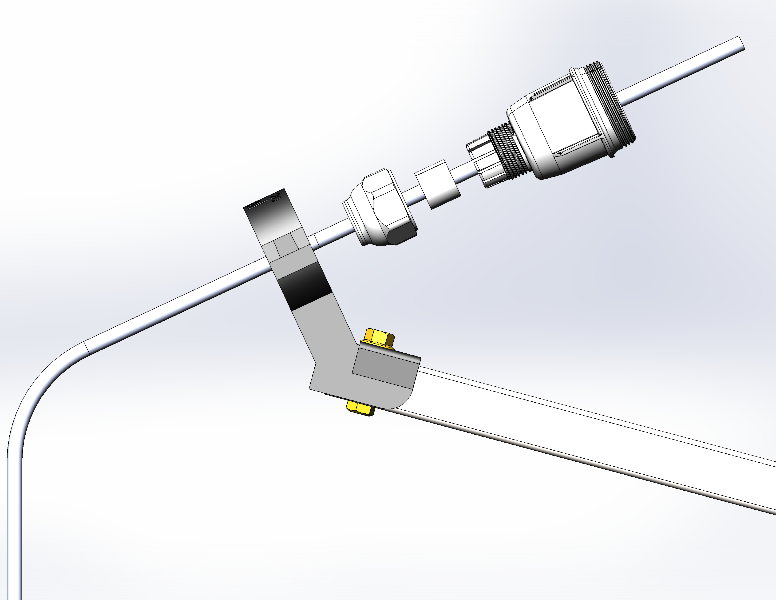
Figure 24 — Cable pulling through the holder and the cable gland
7. Crimp the RJ-45 connector onto the cable and connect it to the mating part on the device housing.
Figure 25 — RJ-45 connector on the device housing
8. Securely tighten the gland body, place the split gland on the cable and insert it into the gland body. Tighten the sealing nut until it stops.
Figure 26 — Installing the cable gland
Incorrect installation of the cable gland can compromise the device sealing.
9. Place the device in the holder and adjust the device to 0° using the holder scale. After adjustment, tighten the screw on the holder.
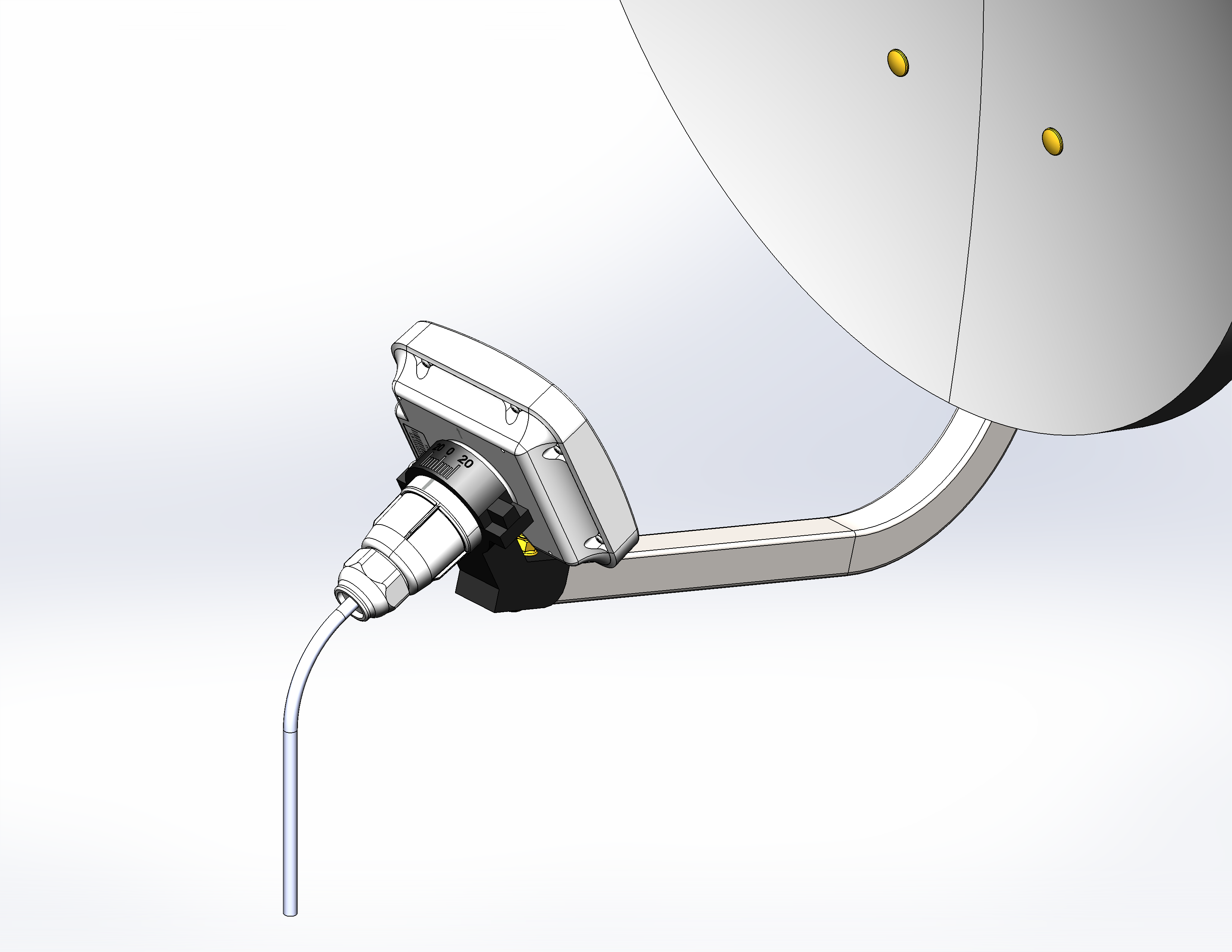
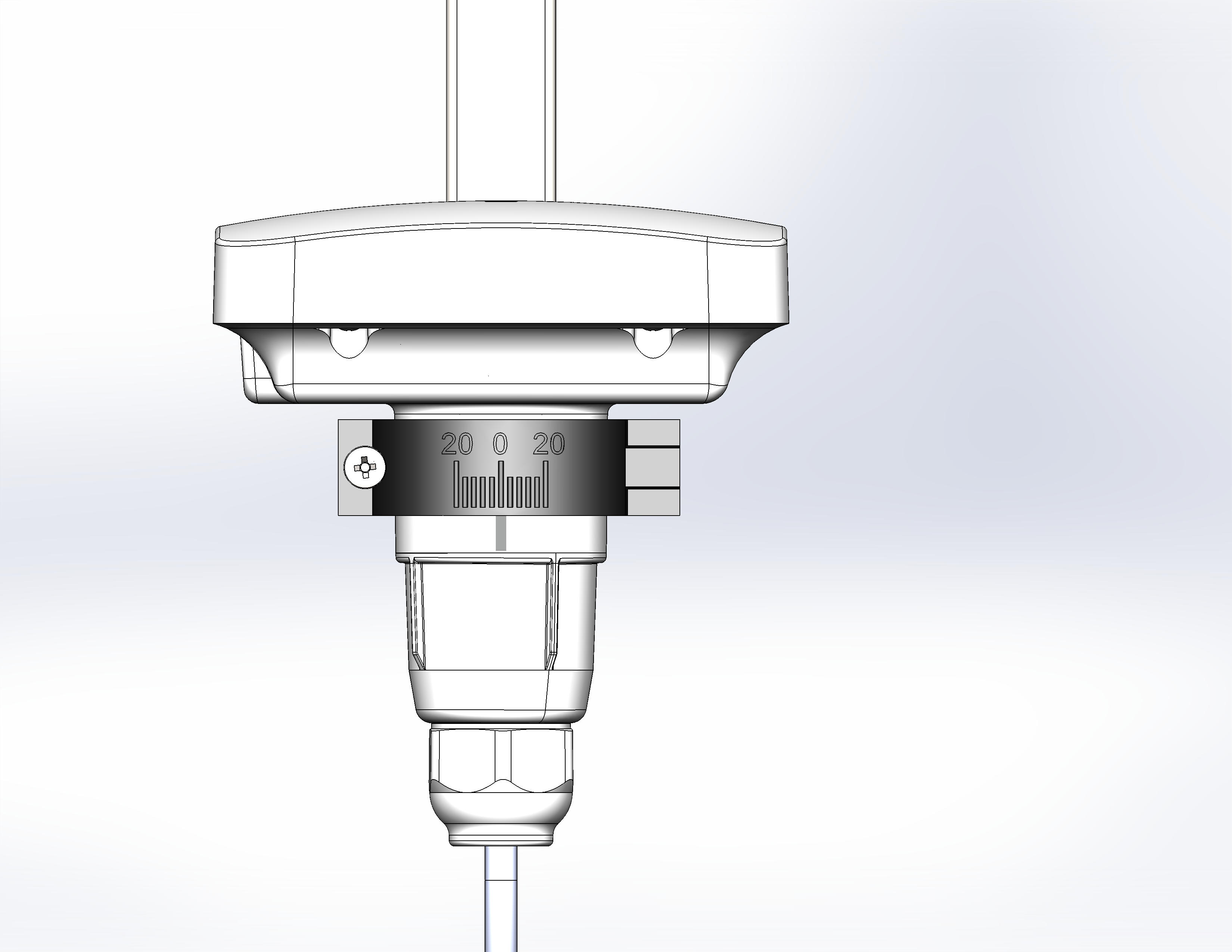
Figure 27 — Installing the device into the holder
10. Place the fixed part of the bracket on the pole as shown in Figure 28 and secure it with the clamps supplied with the device. The final tightening of the clamps is performed in Alignment of devices mounted on an offset parabolic antenna section. Install the chains; do not tighten the chain screws tightly, leaving a gap for installing the movable part of the bracket. Follow the instructions given in the section Rules and recommendations for device installation.
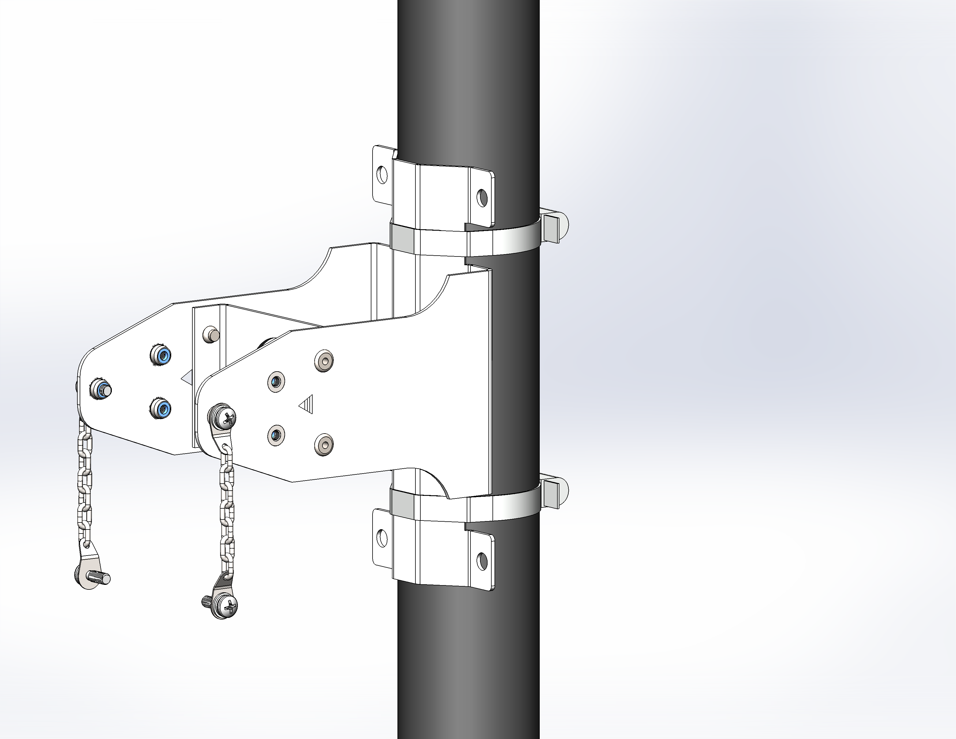
Figure 28 — Installing the fixed part of the bracket
11. Install the reflector on the fixed bracket. During installation, the screws that were not tightened before should fall into the grooves of the movable part of the bracket.
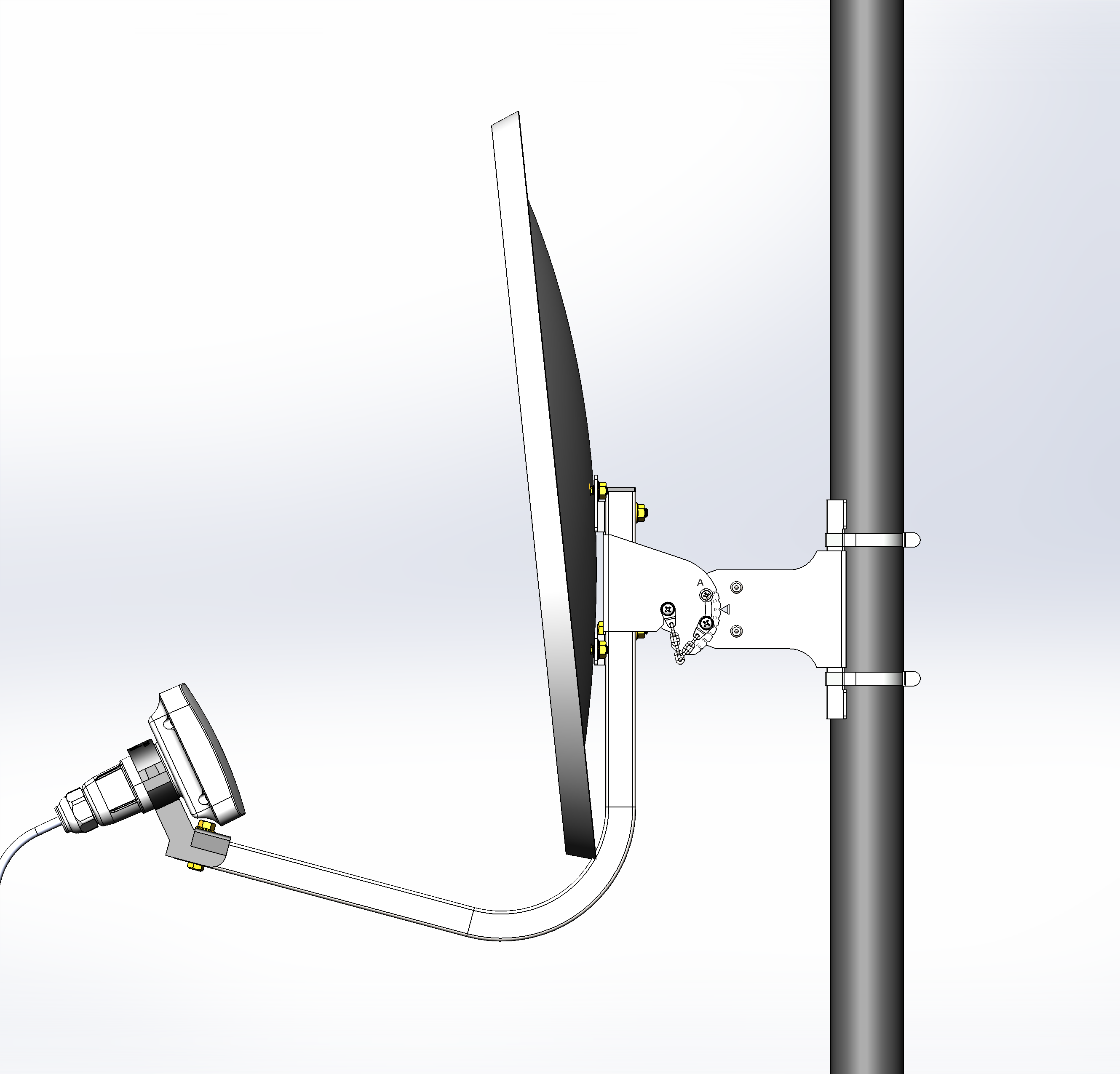
Figure 29 — Installing the reflector on the fixed bracket
12. If necessary, it is possible to install a parabolic antenna on the wall, for example using M6 bolts.
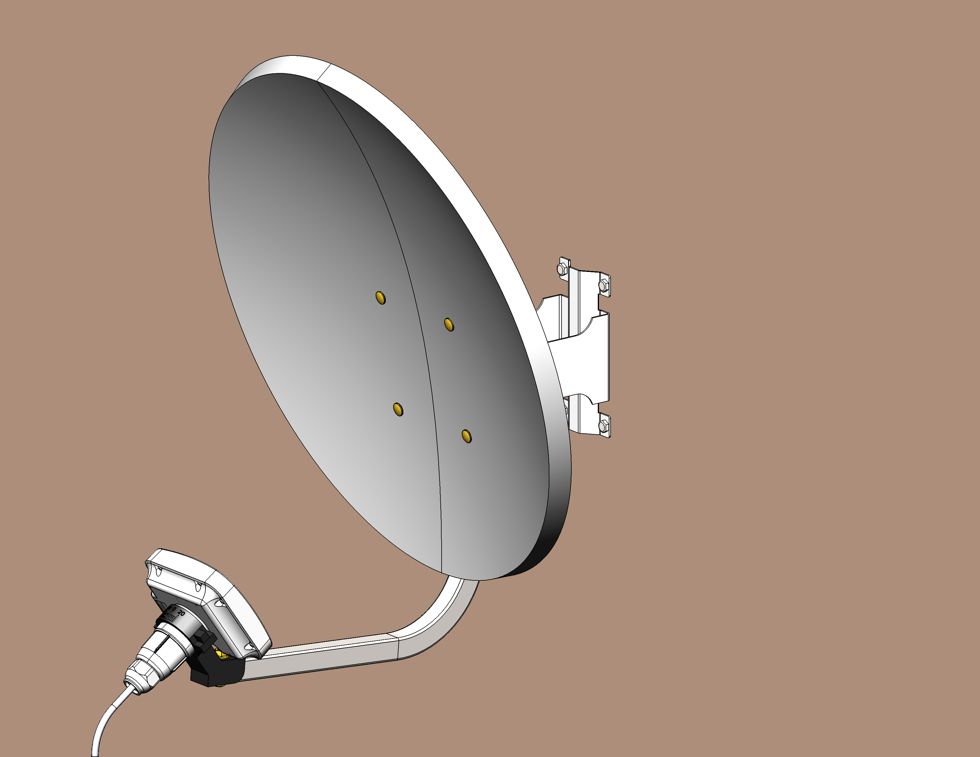
Figure 30 — Mounting a parabolic antenna on the wall
13. Connect the device to the network following the algorithms in the Device connection section. Then proceed to device alignment.
Device alignment
First, the horizontal alignment of the device is performed, then the vertical one.
Alignment of devices mounted on a pole/post/wall
1. Be sure to perform the alignment alternately from both sides, based on the calculated signal level value obtained in the Installation recommendations section (it is required to get the closest possible value).
2. Adjust the position of the devices by directing the antennas approximately to each other, using maps and optical visibility (for example, using binoculars) to the opposite side.
With default settings, the client (STA) does not send a connection request, so to establish a connection, you first need to direct the access point (AP) to the client (STA).
3. In case of establishing сonnection between the devices, sequentially align the devices, achieving a gradual increase in values on the RSSI scale (LED states are provided in the Light Indication section) in both vertical and horizontal planes.
4. In the horizontal plane, one side passes a sector of 45–60 degrees — fixes the maximum, the second side repeats the same action.
5. Next, perform the second pass according to the above scheme. Finally tighten the clamp on the bracket. It is necessary to take into account that during alignment, hitting the side lobe of the radiation pattern may be interpreted as reaching the maximum signal level. To avoid this situation, it is necessary to perform a full pass in the sector and note any nonlinear level changes.
6. Repeat steps 4–5 in the vertical plane. Fix the resulting tilt angle using screws on the chain.
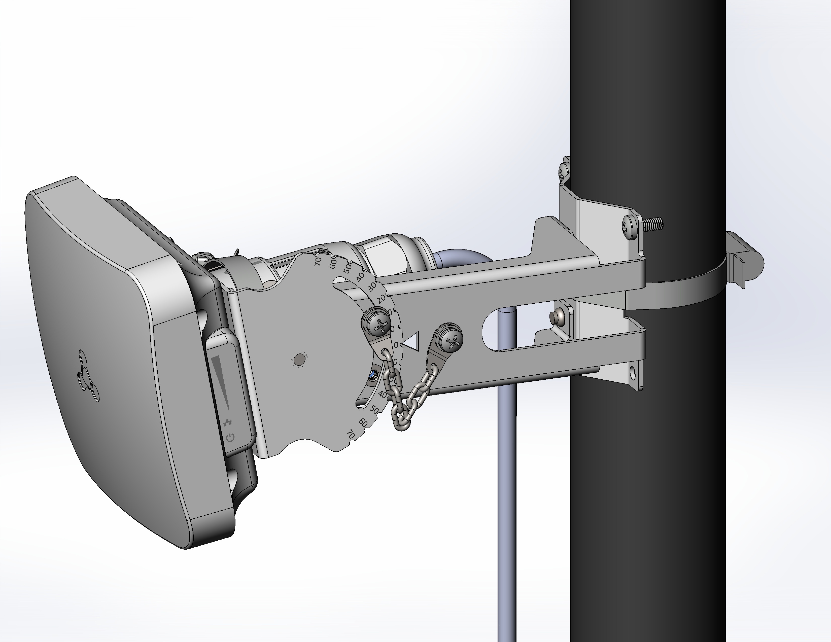
Figure 31 — Setting the required tilt angle
7. For more precise alignment, use the CLI command or web interface (more details in "Antenna Align" submenu), achieving the maximum signal level values.
Alignment of devices mounted on an offset parabolic antenna
1. Be sure to perform the alignment alternately from both sides, based on the calculated signal level value obtained in the Installation recommendations section (it is required to get the closest possible value).
2. Adjust the position of the devices by directing the antennas approximately to each other, using maps and optical visibility (for example, using binoculars) to the opposite side.
With default settings, the client (STA) does not send a connection request, so to establish a connection, you first need to direct the access point (AP) to the client (STA).
3. In case of establishing сonnection between the devices, sequentially align the devices, achieving a gradual increase in values on the RSSI scale (LED states are provided in the Light Indication section) in both vertical and horizontal planes.
4. In the horizontal plane, one side passes a sector of 45–60 degrees — fixes the maximum, the second side repeats the same action.
5. Next, perform the second pass according to the above scheme. Finally tighten the clamps on the bracket unmovable part. It is necessary to take into account that during alignment, hitting the side lobe of the radiation pattern may be interpreted as reaching the maximum signal level. To avoid this situation, it is necessary to perform a full pass in the sector and note any nonlinear level changes.
6. In the vertical plane, repeat steps 4–5: rotate the device to the required angle, using "A" and "B" scales located on the bracket as a guide. The "A" scale represents the tilt angle of the parabolic antenna, while the "B" scale represents the elevation angle. Then fix the resulting angle using the screw on the chain.
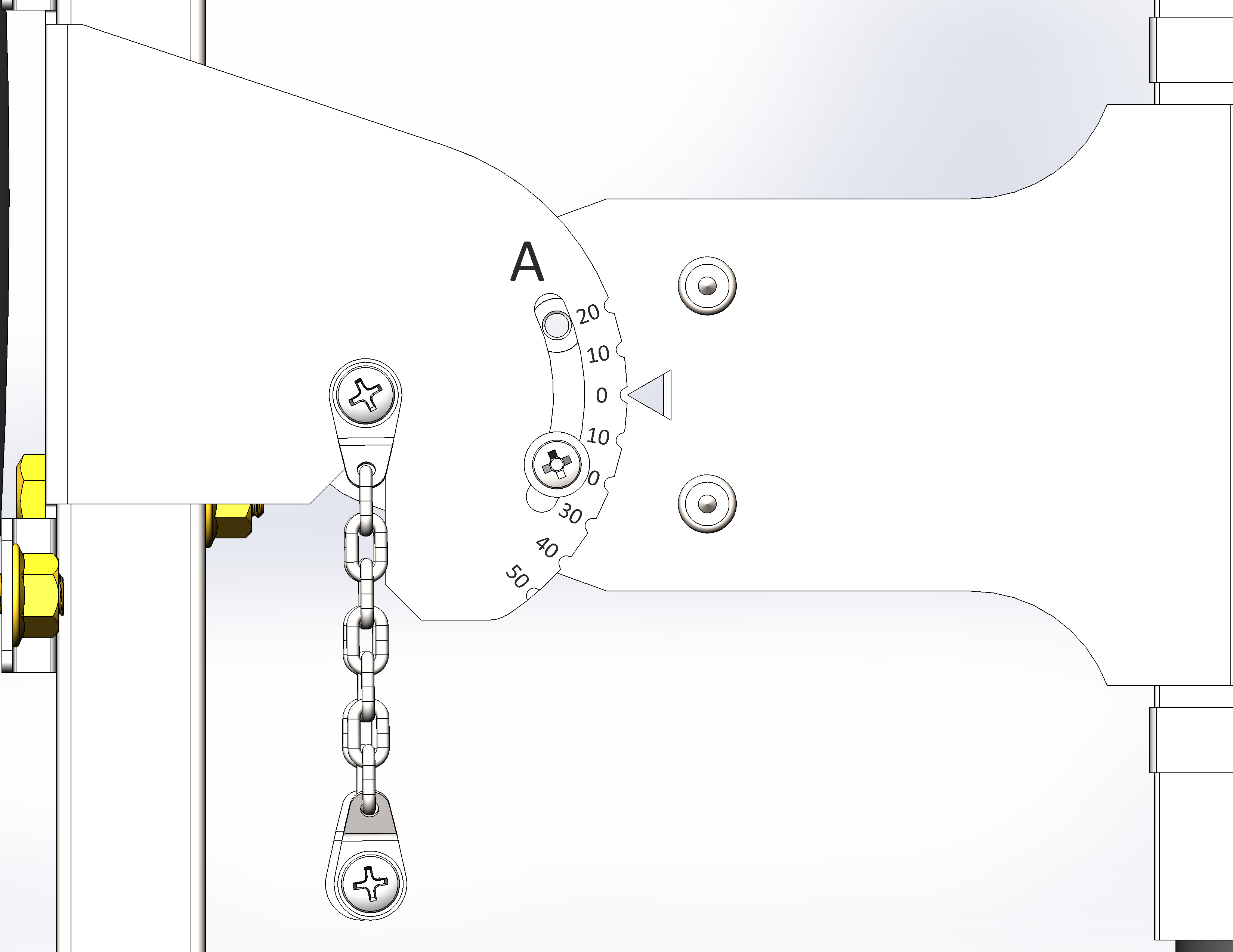
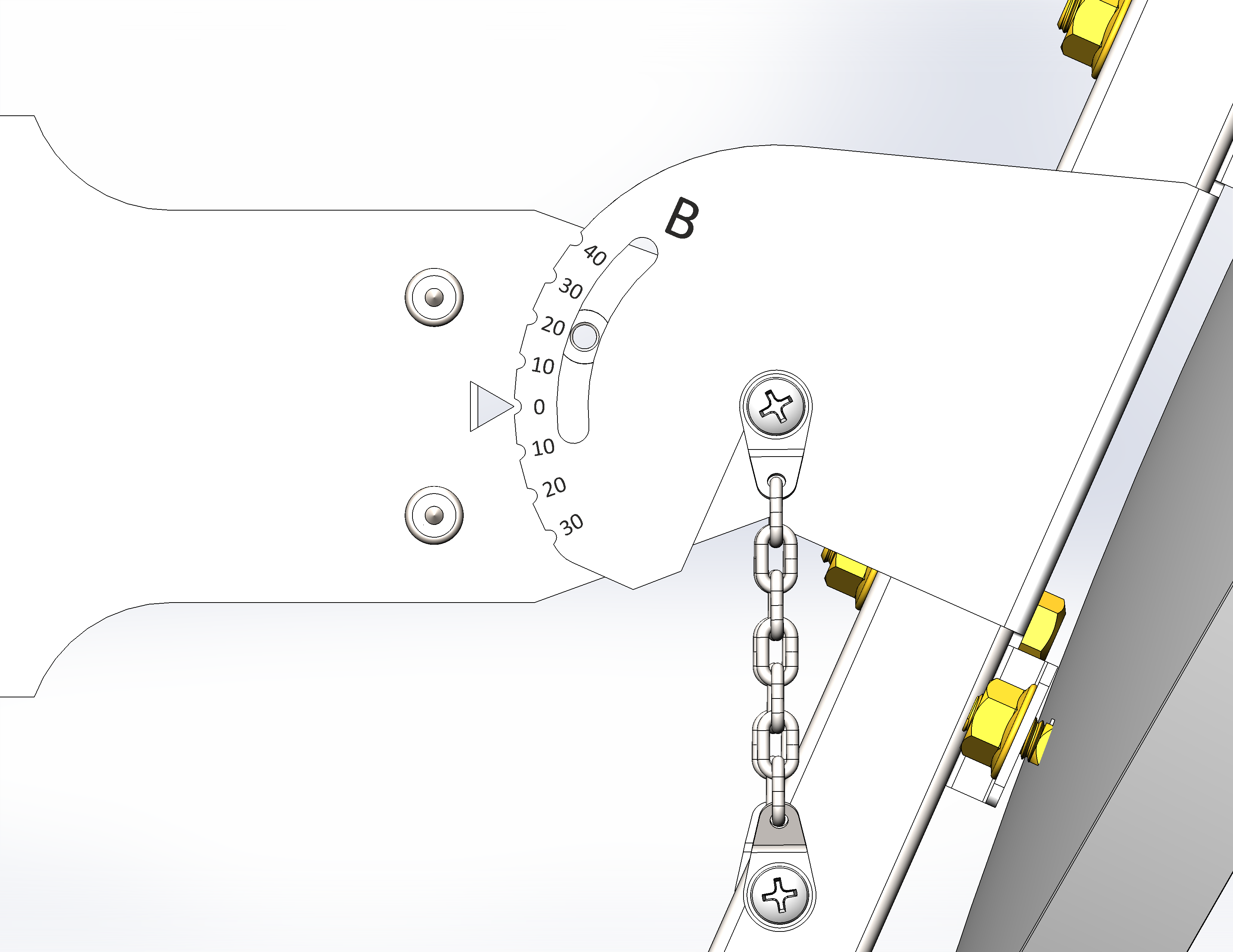
Figure 32 — "A" and "B" scales on the movable part of the bracket
7. When setting the angle on the "A" scale from -10 to 5 degrees, it is recommended to additionally fix the movable part of the bracket with a second screw from the kit.
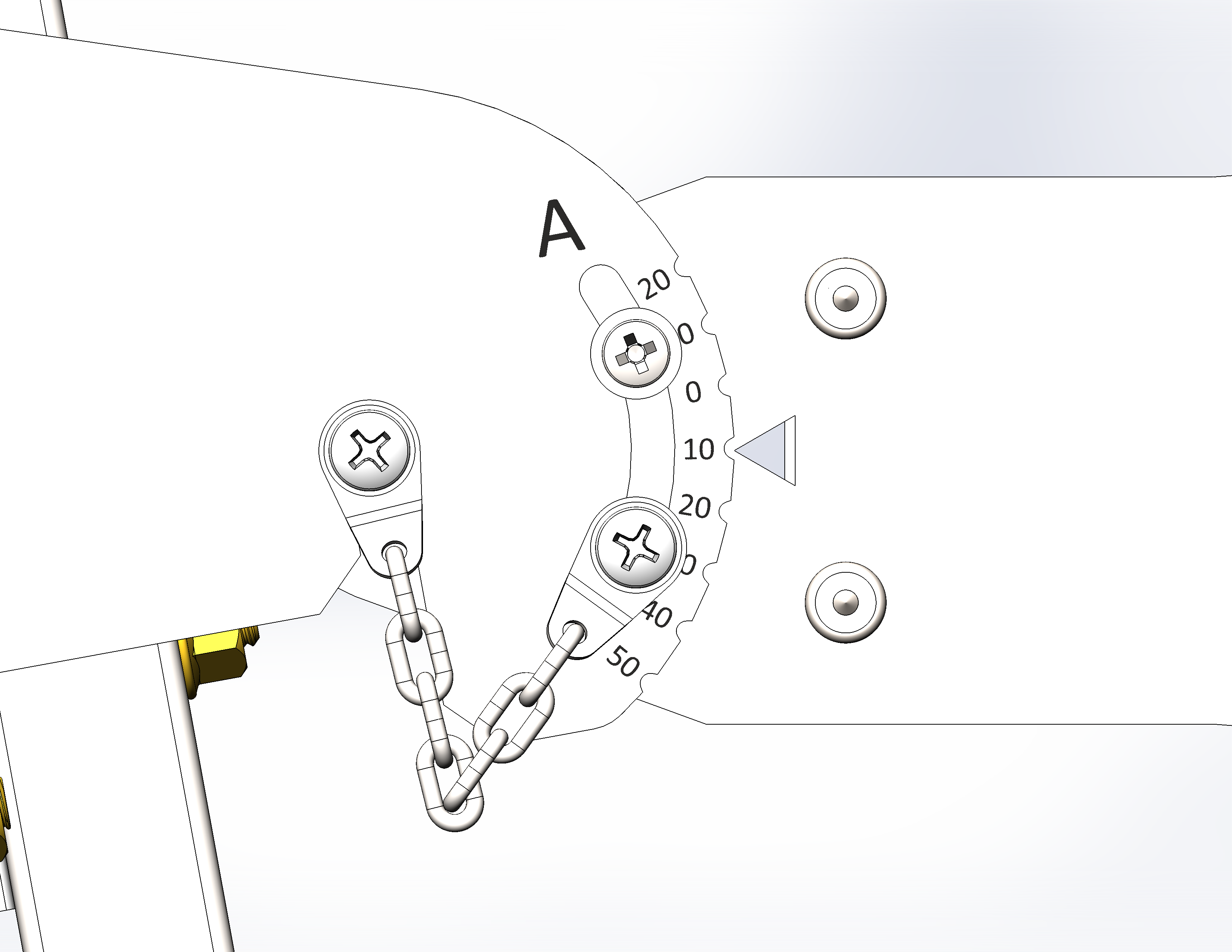
Figure 33 — Additional fixation of the bracket movable part
8. For more precise alignment, use the CLI command or the web interface (more details in "Antenna Align" submenu), achieving the maximum signal level values.
Final device setup
- It is recommended to select and set a static modulation on this and the opposite devices. To select a static modulation, run a continuous ping to the devices. Then, in the "Monitoring" menu, under "Wireless Peer"/"Wireless Clients," note the automatically set modulation and set it statically in the channel transmission rate settings in the "Radio" menu. For reliability, you can set the modulation a couple of points lower than the automatic setting.
- Scan the environment with a spectrum analyzer and select the least congested channel.
- Set the final channel in the "Radio" menu.
Device management via web interface
Getting started
To get started, connect to the device via Ethernet interface using a web browser:
1. Open a web browser, for example, Firefox, Opera, Chrome.
2. Enter the device IP address in the browser address bar.
Factory IP address: 192.168.1.10, subnet mask: 255.255.255.0. By default, the device is capable to obtain an IP address via DHCP.
When the device is successfully detected, username and password request page will be shown in the browser window.
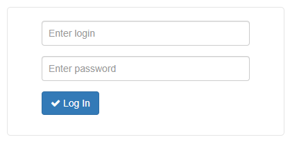
3. Enter username into "Enter Login" and password into "Enter Password" field.
Factory settings: login — admin, password — password.
4. Click "Log In". The device status monitoring menu will open in a browser window.
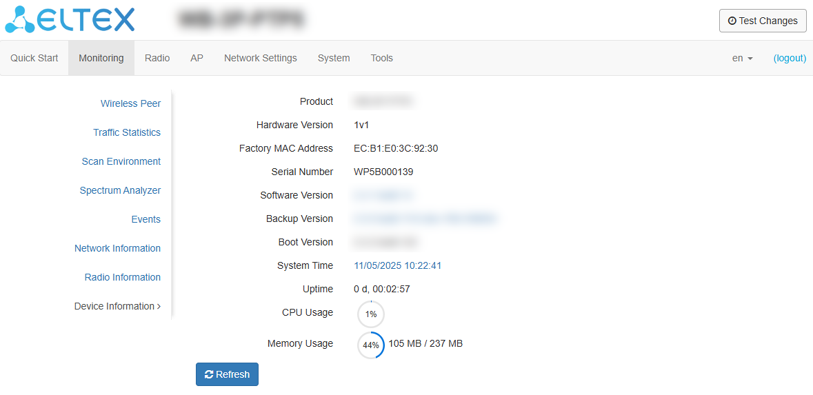
5. If necessary, select the information display language.
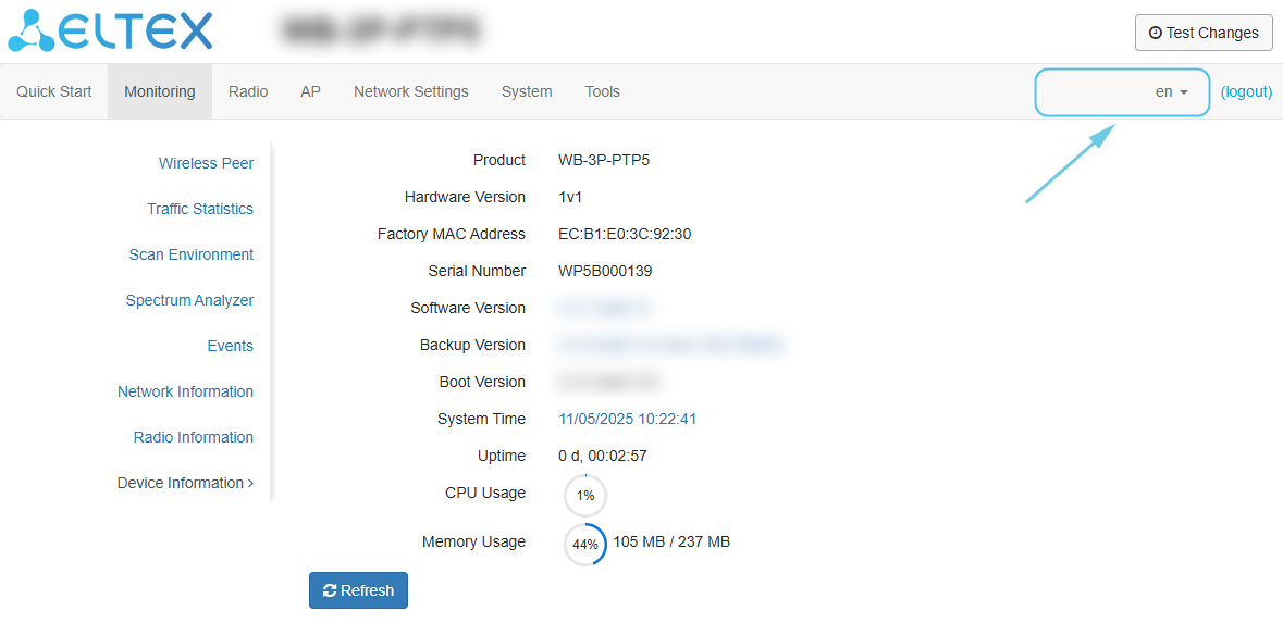
User change
There are two types of users on the device: admin and viewer:
- admin (default password: password) has full access to the device: ability to read and write any settings, full monitoring of the device status.
- viewer has the right to only view the entire configuration of the device without the ability to edit anything; monitoring of the device status is fully accessible.

If to click the "Logout" button, the current user session will be terminated and the authorization window will be displayed:
To change access, specify the appropriate username and password and click the "Log In" button.
Applying configuration and discarding changes
- Applying configuration
Clicking the  button starts the process of saving the configuration to the device flash memory and applying the new settings. All the settings come into operation without device rebooting.
The web interface has a visual indication of the current status of the setting applying process (Table 4).
Table 4 — Visual indication of the current status of the setting application process
| Image | State description |
|---|---|
| After clicking "Apply", the process of settings saving to device memory is launched. This is indicated by the |
| The |


2. Discarding changes
The changes can be discarded only before clicking the "Apply" button. If you click the "Apply" button, all the changed parameters will be applied and saved to device memory. After clicking the "Apply" button, return to the previous settings will not be possible.
The button for discarding changes appears as follows:  .
.
Test mode
The device has a test mode for testing configurations.
To activate it, click the "Test Mode" button in the top panel of the web interface.


After checking the required configuration, click the "Exit from Test Mode" button and select the desired action:

- "Save and Exit" — when pressed, the device will exit test mode and save all configuration changes made and applied in this mode to non-volatile memory. It will be impossible to cancel the changes made in test mode.
- "Cancel and Exit" — when pressed, the device will exit test mode and discard all changes made in this mode. The configuration that was active on the device before enabling test mode will be restored.
If the administrator does not exit test mode within 300 seconds, this will happen automatically, and all changes made in that mode will be undone. After the specified time expires, the configuration will be restored, even if the access to the device was lost as a result of these actions.
Web interface basic elements
Navigation elements of the web interface are shown in the figure below.
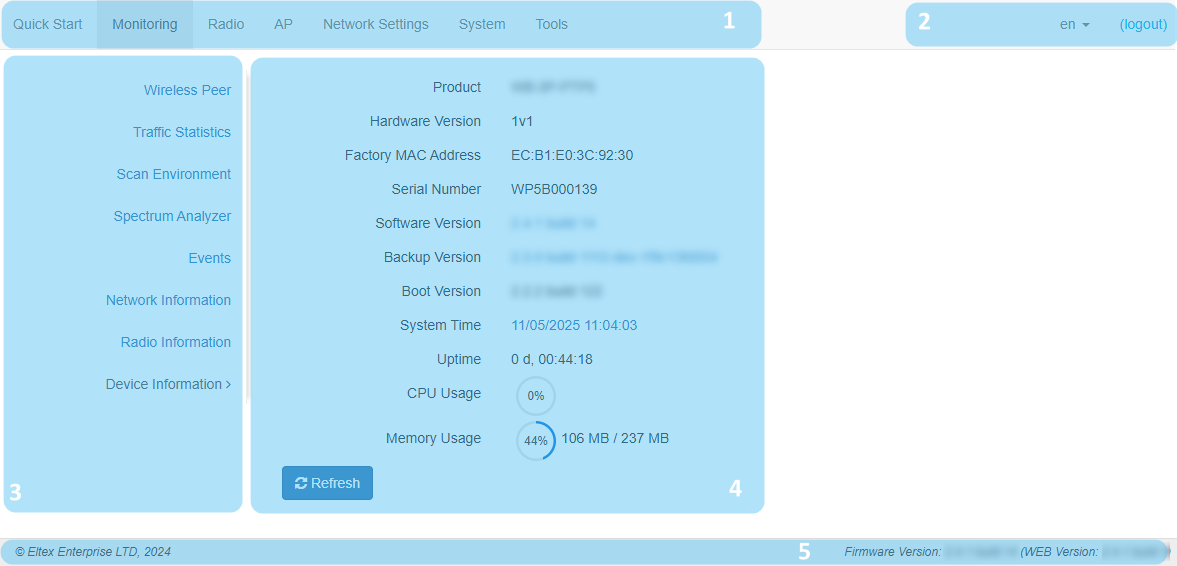
User interface window is divided into five general areas:
- Menu tabs categorize the submenu tabs: Quick Start, Monitoring, Radio, AP (the "AP" menu is only available in the "Access Point PTP" or "Access Point PMP" device mode) or STA (the "STA" menu is only available in the "Station" device mode), Network Settings, System, Tools.
- Interface language selection and Logout button designed to end a session in the web interface under a given user.
- Submenu tabs allow one to control settings field.
- Device configuration field displays data and configuration.
- Information field displays current firmware version.
"Quick Start" menu
In the "Quick Start" menu, the basic configuration of the device is performed.
"Quick Start" submenu
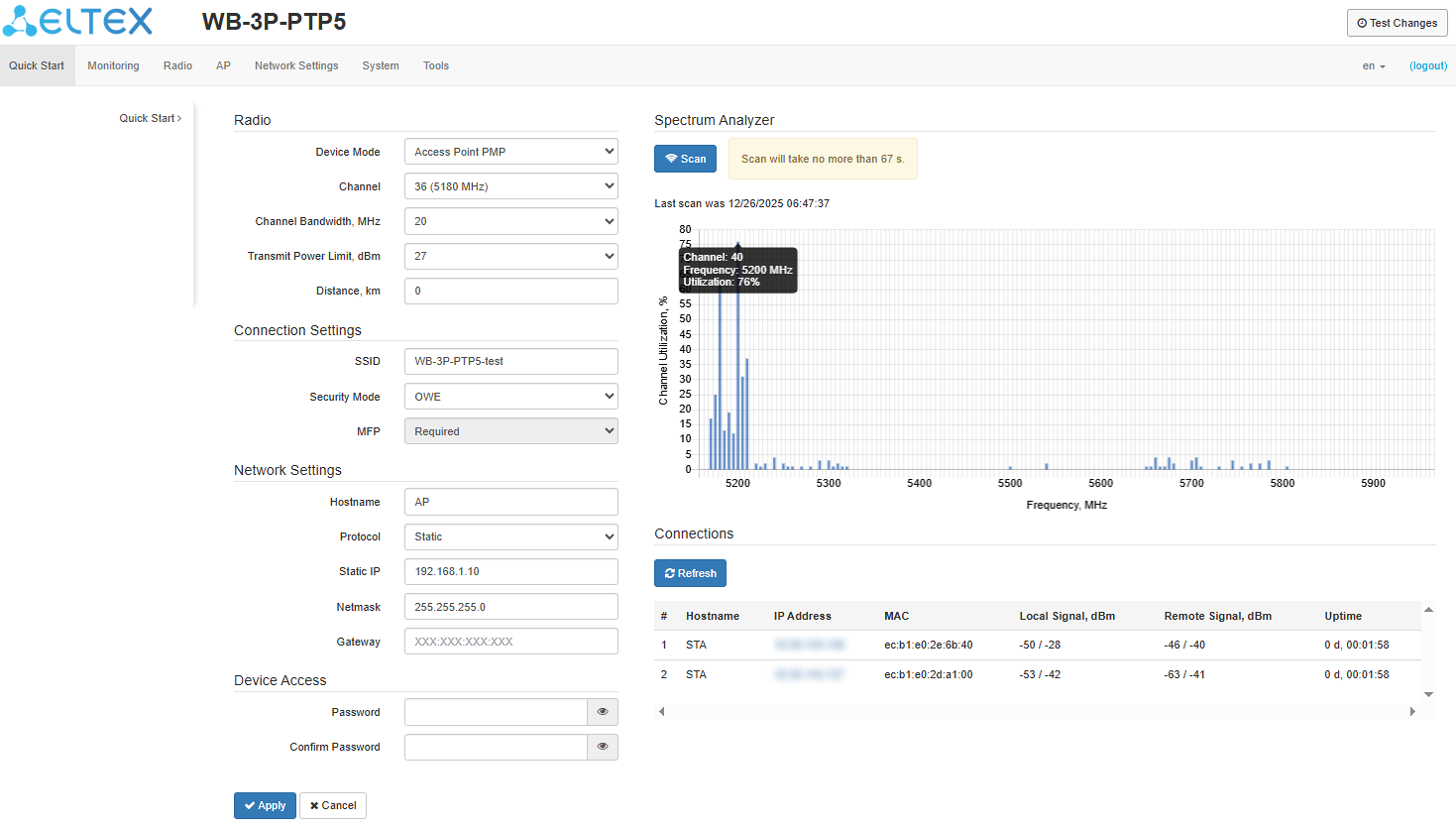 Radio:
In the "Radio" section, the main parameters of the device radio interface are configured.
- Device Mode — operating mode of the device radio interface. The following modes are available:
- Access Point PTP — Point-to-Point;
- Access Point PMP — Point-to-Multipoint;
- Station — wireless client (STA).
- Channel — selecting a data transmission channel. If the "Auto Channel" is checked in the Radio menu, this setting will be locked;
- Channel Bandwidth, MHz — channel bandwidth on which the device operates. The parameter can take values of 5, 10, 20, 40, 80 and 160 MHz;
- Primary Channel — parameter can only be changed if the bandwidth of a statically specified channel is equal to 40 MHz. The 40 MHz channel can be considered as consisting of two adjacent 20 MHz channels. These two 20 MHz channels are called primary and secondary channels:
- Upper — primary channel will be the upper 20 MHz channel in the 40 MHz band;
- Lower — primary channel will be the lower 20 MHz channel in the 40 MHz band.
- Fixed Center Frequency — when сhecked, all traffic (data and control packets) will be transmitted on the specified channel center frequency with the specified bandwidth (40/80/160 MHz). The function is proprietary, the transmission is not carried out according to IEEE 802.11 standards, which assume the use of different center frequencies for data and control traffic with a channel bandwidth of 40/80/160 MHz;
- Transmit Power Limit, dBm — Wi-Fi transmitter signal power adjustment in dBm;
- Distance, km — distance between devices in kilometers. Changing the distance value will change the ACK timeout value. The distance should be rounded up. For example, if the distance between devices is 3.2 km, then 4 km should be specified.
The 5 and 10 MHz bandwidths are only available in IEEE 802.11a/n/ac mode. To change the 802.11 mode, go to the Radio menu.
The "Channel", "Channel Width", "Primary Channel" parameters are only available when the device mode is "Access Point PTP" or "Access Point PMP".
Connection Settings:
- SSID — virtual wireless network name;
- Security Mode — wireless network access security mode:
- Off — ;
- OWE (Opportunistic Wireless Encryption) — encryption method that provides the security of data transmitted over an unsecured network. In this case, users do not need to do any additional actions and enter a password to connect to the network;
- WPA2, WPA3 — encryption methods, when selecting one of the methods, the following setting will be available:
- WPA Key — key/password required to connect to the wireless network. The key length is from 8 to 63 characters.
- MFP — management frame protection (available for WPA2, WPA3 and OWE security modes. When selecting the WPA3 or OWE security mode, MFP is set to Required. When other modes are selected, it is set to Not Required):
- Not Required — management frame protection is disabled;
- Capable — management frame protection works, if a wireless network supports MFP. The device can connect to a network that does not support MFP;
- Required — management frame protection is enabled. The device cannot connect to a wireless network that does not support MFP.
Network Settings:
- Hostname — network name of the device, a string of 1–63 characters is specified: Latin uppercase and lowercase letters, digits, the hyphen sign "-" (the hyphen cannot be the last character in the name);
- Protocol — protocol for connection of the device via Ethernet interface to service provider network:
- DHCP — operating mode in which IP address, subnet mask, DNS server address, default gateway and other parameters required for operation in the network are obtained from DHCP server automatically;
- Static — operating mode in which IP address and all the necessary parameters for WAN interface are assigned statically. If "Static" is selected, the following parameters will be available to set:
- Static IP — device WAN interface IP address in the provider network;
- Netmask — external subnet mask;
- Gateway — address to which the packet is sent if the route in routing table is not found for it.
Device Access:
In the "Device Access" section the password can be changed.
When logging via web interface, administrator (default password: password) has full access to the device: reading and writing any settings, full monitoring of the device status. To change the password, first enter the new password in the "Password" field, then in the "Confirm password" field, and click the "Apply" button to save the new password.
Spectrum Analyzer:
The "Spectrum Analyzer" section is used to launch and monitor the spectrum analyzer.
The WB-3P-PTP5 devices can launch the spectrum analyzer on the Radio 5 GHz.
When the spectrum analyzer is launched, the radio interface will be switched to scanning mode, which will interrupt all Wi-Fi connections on this radio interface.
To start the spectrum analyzer, click the "Scan" button. The information window located to the right of the button displays the time in seconds that has passed since the start of the scan. The scan on the Radio 5 GHz will take no more than 1.5 minutes.
- Last scan was... — date and time of the last scan;
- Channel Utilization — information about the radio channel congestion, expressed as a percentage;
- Frequency — channel frequency, on which scanning was performed, MHz;
- Channel — channel number corresponding to a given frequency.
The spectrum analyzer analyzes all channels in the range, regardless of the settings on the radio interface.
Connections:
The "Connections" section displays information about the status of connected devices.
- # — number of the connected device in the list;
- Hostname — network device name;
- IP Address — IP address of the connected device;
- MAC — MAC address of the connected device;
- Local Signal — received signal level, dBm;
- Remote Signal — received signal level of the remote device, dBm;
- Uptime — connection time.
To apply a new configuration and save settings to non-volatile memory, click the "Apply" button. Click the "Cancel" button to discard the changes.
"Monitoring" menu
The "Monitoring" menu displays the current system status.
Wireless Peer/Wireless Clients
The "Wireless Peer"/"Wireless Clients" submenu displays information about the status of connected devices. Information about connected devices is not displayed in real time. To update the information on the page, click the "Refresh" button.
Depending on the device mode, "Access Point PTP" or "Access Point PMP", the "Wireless Peer" or "Wireless Clients" submenu will be available respectively.
For easy monitoring, it is possible to select the parameters to display. To do this, click  . If to click the "By Default" button, the default parameters will be displayed.
The following filters are available for searching connected devices: by all fields, hostname, IP address, MAC address. To select a filter, click  . The functionality is only available in the "Access Point PMP" device mode.
If the Link Quality, Link Quality Common, Link Capacity, RSSI and Remote RSSI values are highlighted in orange, the connection quality is deteriorating. If the values are highlighted in red, this indicates a significant deterioration in the connection. It is recommended to take measures to improve the connection conditions.
Below are examples of the "Wireless Peer"/"Wireless Clients" submenus in the "Access Point PTP", "Access Point PMP", and "STA" device modes, respectively.
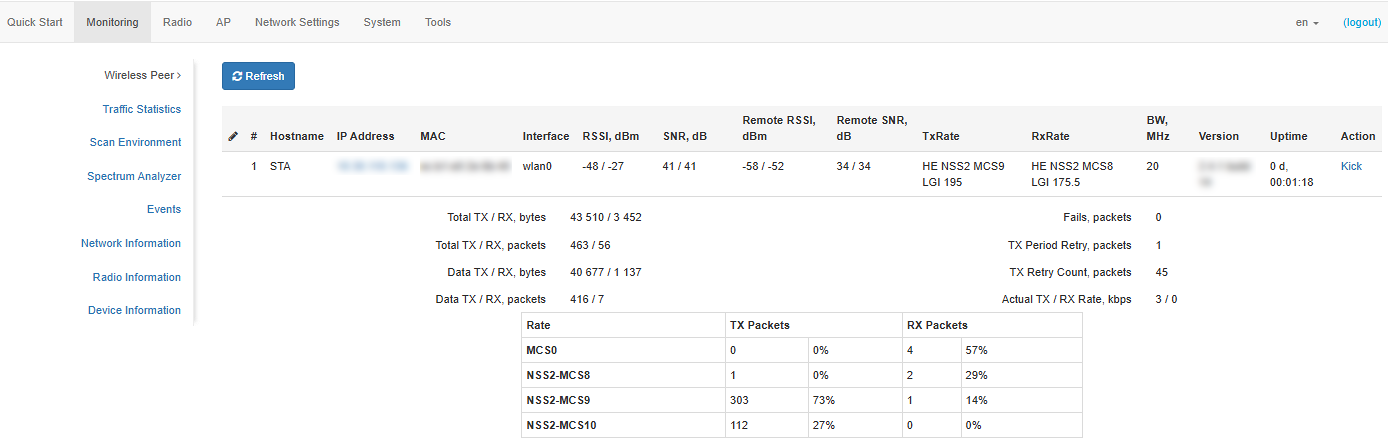
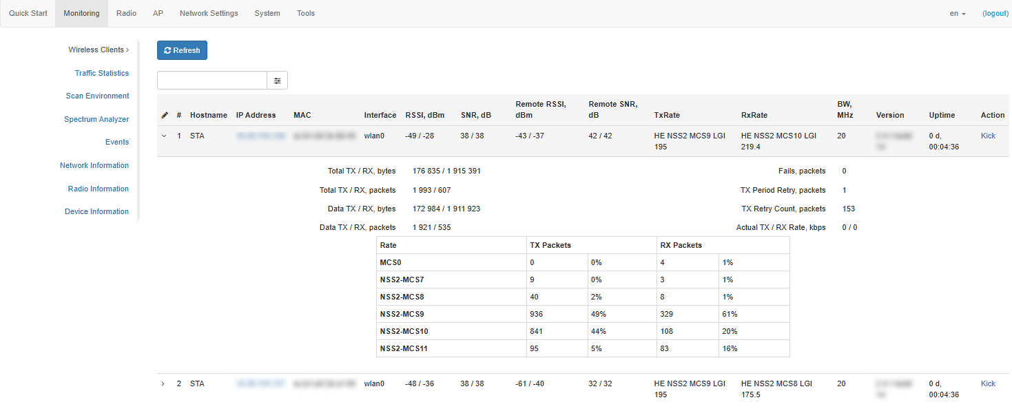
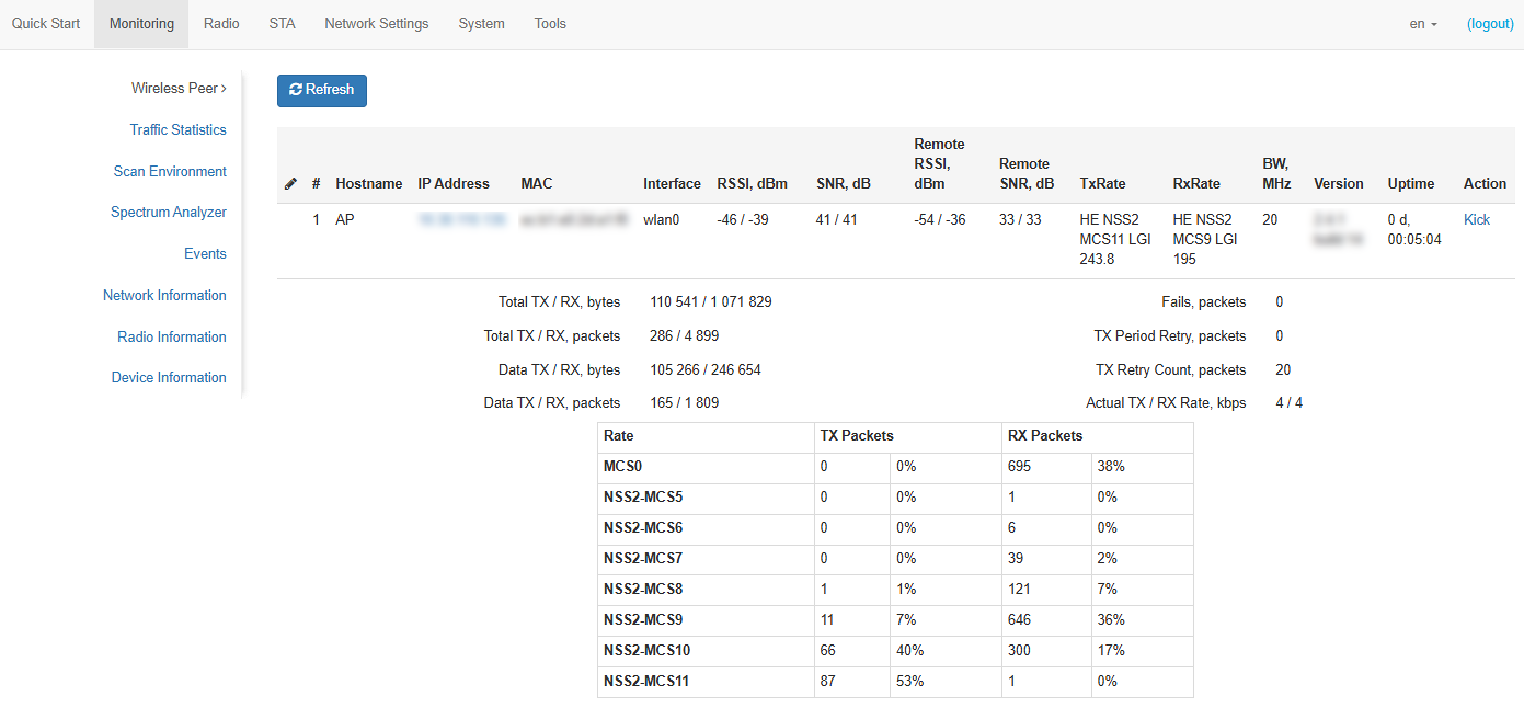
- # — number of the connected device in the list;
- Hostname — network device name;
- IP Address — IP address of the connected device;
- MAC — MAC address of the connected device;
- Interface — WB-3P-PTP5 interaction interface with the connected device;
- Link Capacity — parameter that displays the efficiency of modulation on the transmission used by the device. It is calculated based on the number of packets transmitted to the client on each modulation, and the reduction factors. The maximum value is 100% (meaning that all packets are transmitted to the client at maximum modulation for the maximum Nss type supported by the client). The minimum value is 2% (in the case when the packets are transmitted on the modulation Nss1MCS0 for a remote device with MIMO 3×3 support). The parameter value is calculated for the last 10 seconds;
- Link Quality — parameter that displays the status of the link to the remote device, calculated based on the number of retransmit packets sent to the remote device. The maximum value is 100% (all transmitted packets were sent on the first attempt), the minimum value is 0% (no packets were successfully sent to the remote device). The parameter value is calculated for the last 10 seconds;
- Link Quality Common — parameter that displays the status of the link to the remote device, calculated based on the number of retransmit packets sent to the remote device. The maximum value is 100% (all transmitted packets were sent on the first attempt), the minimum value is 0% (no packets were successfully sent to the client). The parameter value is calculated for the entire client connection time;
- RSSI — received signal level, dBm;
- SNR — signal-to-noise ratio, dB;
- Remote RSSI — received signal level of the remote device, dBm;
- Remote SNR — signal-to-noise ratio of the remote device, dB;
- TxRate — channel data transfer rate, Mbps;
- RxRate — channel data reception rate, Mbps;
- BW — transmission bandwidth of the wireless channel, MHz;
- Actual TX Rate — average data transfer rate over the last 10 seconds, Mbit/s;
- Actual RX Rate — average data reception rate over the last 10 seconds, Mbit/s;
- Version — firmware version of the connected device;
- Uptime — connection time;
- Action — if to press "Kick" button, the connection with the connected device will be broken. After disconnecting, the device will reconnect.;
- Total TX/RX, bytes — number of bytes sent/received on the connected device;
- Total TX/RX, packets — number of packets sent/received on the connected device;
- Data TX/RX, bytes — number of data bytes sent/received on the connected device;
- Data TX/RX, packets — number of data packets sent/received on the connected device;
- Fails, packets — number of packets sent with errors on the connected device;
- TX Period Retry, packets — number of transmission retries to the connected device in the last 10 seconds;
- TX Retry Count, packets — number of transmission retries to the connected device during the entire connection;
- Actual TX/RX Rate, Kbps — current traffic transmission rate at the moment.
"Traffic Statistics" submenu
The "Traffic Statistics" submenu displays traffic reception/transmission rate graphs for the last 3 minutes, as well as information on the amount of transmitted/received traffic since the device was turned on.
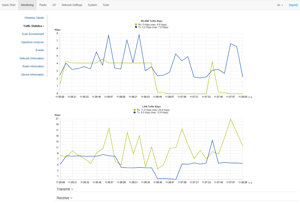
The LAN Tx/Rx graph shows the rate of the transmitted/received traffic via Ethernet interface of the device for the last 3 minutes. The graph is automatically updated every 6 seconds.
The WLAN0 Tx/Rx graph shows the rate of transmitted/received traffic via radio interface of the device for the last 3 minutes. The graph is automatically updated every 6 seconds.
"Transmit" table description:
- Interface — name of the interface;
- Total Packets — number of successfully sent packets;
- Total Bytes — number of successfully sent bytes;
- Total Drop — number of rejected packets;
- Errors — number of errors.

"Receive" table description:
- Interface — name of the interface;
- Total Packets — number of successfully received packets;
- Total Bytes — number of successfully received bytes;
- Total Drop — number of rejected packets;
- Errors — number of errors.

"Scan Environment" submenu
In the "Scan Environment" submenu, air scanning and detection of neighboring devices are carried out.
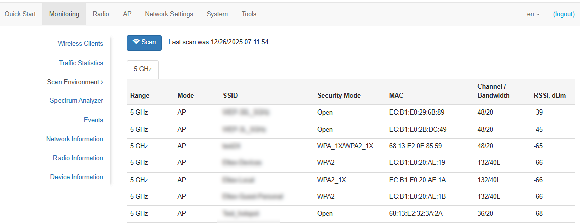
To start the scanning process, click the "Scan" button. After scanning is complete, a list of detected devices and information about them will appear:
- Last scan was... — date and time of the last scan;
- Range — specifies the 5 GHz range, in which the device was detected;
- Mode — device radio interface operating mode;
- SSID — SSID of the detected device;
- Security mode — security mode of the detected device;
- MAC — MAC address of the detected device;
- Bandwidth — radio channel on which the detected device operates;
- RSSI — the level with which the device receives the signal of the detected device, dBm.
While scanning the environment, the device radio interface will be disabled, which will make it impossible to transfer data to Wi-Fi clients during scanning.
"Spectrum Analyzer" submenu
The "Spectrum Analyzer" submenu is used to launch and monitor the spectrum analyzer.
On the WB-3P-PTP5 devices, it is possible to launch the spectrum analyzer on the Radio 5 GHz radio interface.
Launching the spectrum analyzer on the radio interface
When the spectrum analyzer is launched, the radio interface will be switched to scanning mode, which will interrupt all Wi-Fi connections on this radio interface.
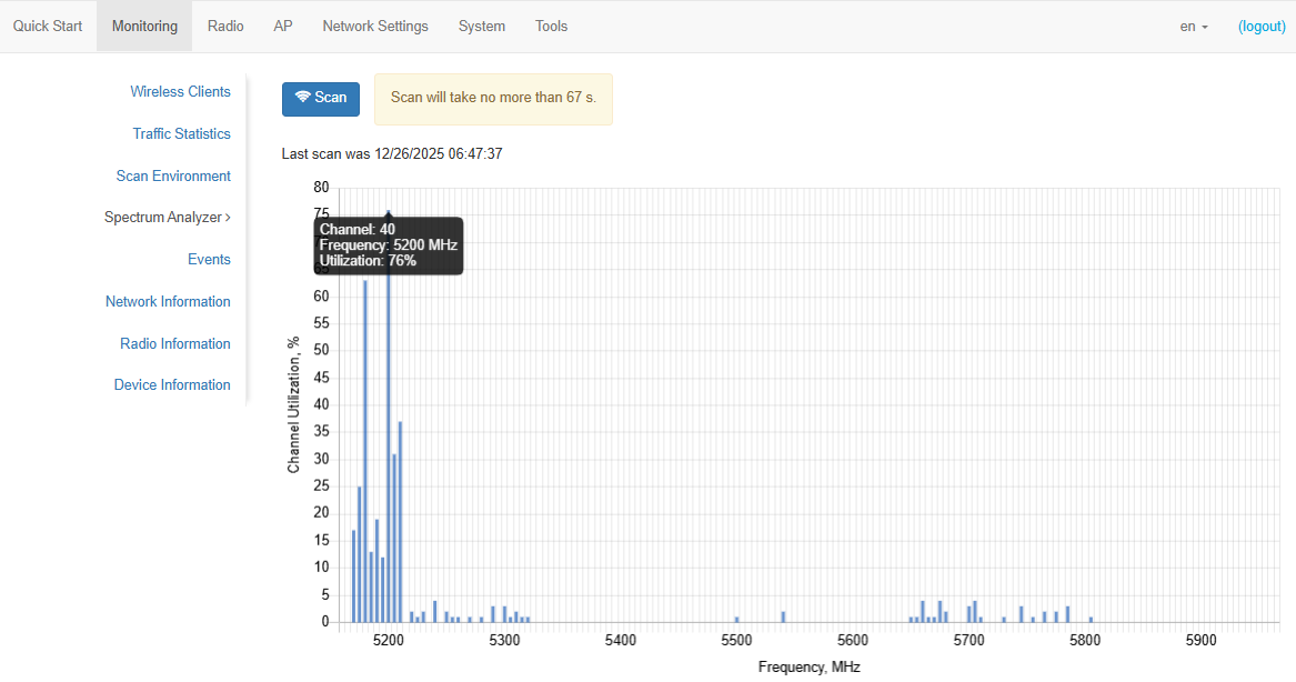
To start the spectrum analyzer, click the "Scan" button. The information window located to the right of the button displays the time in seconds that has passed since the start of the scan. The spectrum analyzer operation time on Radio 5 GHz is no more than 1.5 minutes.
- Last scan was... — date and time of the last scan;
- Channel Utilization — information about the radio channel congestion, expressed as a percentage;
- Frequency, MHz — channel frequency, on which scanning was performed, MHz;
- Channel — channel number corresponding to a given frequency.
The spectrum analyzer analyzes all channels in the range, regardless of the radio interface settings.
"Events" submenu
In the "Events" submenu, it is possible to view a list of real-time informational messages which contains the following information:
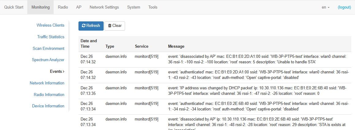
- Date and Time — date and time when the event was generated;
- Type — category and severity level of the event;
- Service — name of the process that generated the message;
- Message — event description.
Table 5 — Description of event severity levels
| Level | Message severity level | Description |
|---|---|---|
| 0 | Emergency | A critical error has occurred in the system, the system may not work properly |
| 1 | Alert | Immediate intervention is required |
| 2 | Critical | A critical error has occurred in the system |
| 3 | Error | An error has occurred in the system |
| 4 | Warning | Warning, non-emergency message |
| 5 | Notice | System notice, non-emergency message |
| 6 | Informational | Informational system messages |
| 7 | Debug | Debugging messages provide the user with information to correctly configure the system |
To receive new messages in the event log, click "Refresh".
If necessary, all old messages can be deleted from the log by clicking the "Clear" button.
"Network Information" submenu
In the "Network Information" submenu, general network settings of the device can be viewed.
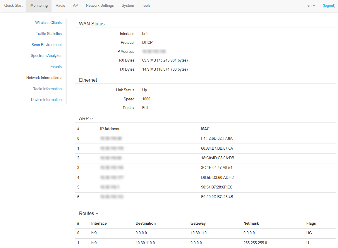
WAN Status:
- Interface — name of the bridge interface;
- Protocol — protocol used for access to WAN;
- IP address — device IP address in external network;
- RX Bytes — number of bytes received on WAN;
- TX Bytes — number of bytes sent from WAN.
Ethernet:
- Link Status — Ethernet port status;
- Speed — Ethernet port connection speed;
- Duplex — data transfer mode:
- Full — full duplex;
- Half — half-duplex.
ARP:
The ARP table contains mapping information between IP and MAC addresses of neighboring network devices:
- IP address — device IP address;
- MAC — device MAC address.
Routes:
- Interface — name of the bridge interface;
- Destination — IP address of destination host or subnet that the route is established to;
- Gateway — IP address of the gateway through which access to the destination is carried out;
- Netmask — subnet mask;
- Flags — certain route characteristics.
The following flag values exist:
- U — means that the route is created and passable;
- H — indicates the route to the specific host;
- G — means that the route lies through the external gateway. System network interface provides routes in the network with direct connection. All other routes lie through the external gateways. G flag is used for all routes except for the routes in the direct connection networks;
- R — indicates that the route was most likely created by a dynamic routing protocol running on the local system using the reinstate parameter;
- D — indicates that the route was added as a result of receiving an ICMP Redirect Message. When the system learns the route from the ICMP Redirect message, the route will be added into the routing table in order to exclude redirection for the following packets intended for the same destination;
- M — means that the route was modified — likely by a dynamic routing protocol running on a local system with the "mod" parameter applied;
- A — points to a buffered route to which an entry in the ARP table corresponds;
- C — means that the route source is the core routing buffer;
- L — indicates that the destination of the route is one of the addresses of this computer. Such "local routes" exist in the routing buffer only;
- B — means that the route destination is a broadcasting address. Such "broadcast routes" exist in the routing buffer only;
- I — indicates that the route is connected to a ring (loopback) interface for a purpose other than to access the ring network. Such “internal routes” exist in the routing buffer only;
- ! — means that datagrams sent to this address will be rejected by the system.
"Radio Information" submenu
In the "Radio Information" submenu, the current status of the device radio interface is displayed.
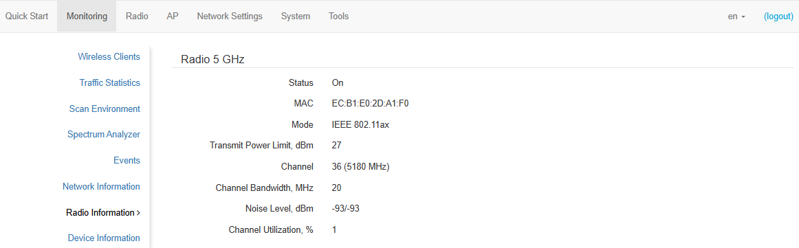
The device radio interface can be in two states: "On" and "Off". Depending on the interface status, the following information is available for monitoring:
“Off”:
- Status — radio interface state;
- MAC — radio interface MAC address;
“On”:
- Status — radio interface state;
- MAC — MAC address of radio interface;
- Mode — radio interface operating mode according to IEEE 802.11 standards;
- Transmit Power Limit, dBm — signal power at which the radio interface operates;
- Connection status — connection status of the client (STA) to the access point (AP). It is available for STA mode only;
- Channel — number of the wireless channel on which the radio interface is running;
- Channel Bandwidth, MHz — channel bandwidth on which the radio interface is running.
- Noise Level, dBm — noise level of the channel on which the radio interface operates;
- Channel Utilization — information about the radio channel congestion, expressed as a percentage.
"Device Information" submenu
The "Device Information" submenu displays main device parameters.
- Product — device model name;
- Hardware Version — device hardware version;
- Factory MAC Address — device WAN interface MAC address, factory set;
- Serial Number — device serial number, factory set;
- Software Version — device firmware version;
- Backup Version — previously installed firmware version;
- Boot Version — device firmware boot version;
- System Time — current time and date, set in the system;
- Uptime — operating time since the last time the device was turned on or rebooted;
- CPU Usage — average percentage of CPU load over the last 5 seconds;
- Memory Usage — percentage of device RAM usage.
"Radio" menu
In the "Radio" menu, the wireless interface can be configured.
"Radio" submenu
In the "Radio" submenu, the main parameters of the device radio interface can be configured.
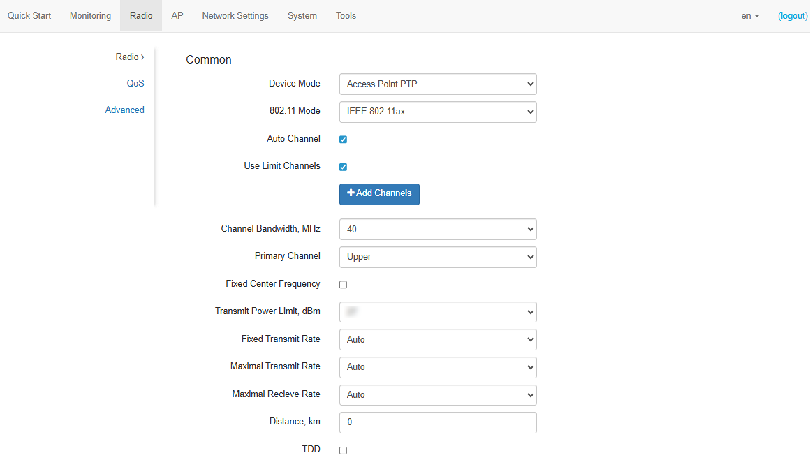
- Device Mode — operating mode of the device radio interface. The following modes are available:
- Access Point PTP — Point-to-Point;
- Access Point PMP — Point-to-Multipoint;
- Station — wireless client (STA).
- 802.11 Mode — interface operating mode according to standards:
- IEEE 802.11ax;
- IEEE 802.11a/n/ac;
- IEEE 802.11a/n/ac/ax.
- Auto Channel — when checked, the device will automatically select the least congested radio channel for the radio interface operation. When unchecked, channel field appears;
- Channel — select channel for data transmission;
- Use Limit Channels — when checked, the device will use a user-defined list of channels to work in automatic channel selection mode. If "Use Limit channels" is unchecked or there are no channels in the list, the device will select the operation channel from all available channels in the given band. The 5 GHz band channels: 32–193;
- Limit Channels — setting is available in the device mode "Station". When checked, the device will use a user-defined list of channels to scan and detect remote devices. If the "Limit Channels" is unchecked or there are no channels in the list, the device will scan all available channels in the given frequency range. The 5 GHz band channels: 32–193;
- Сhannel Bandwidth, MHz — channel bandwidth, on which the device operates. The parameter may take values of 5, 10, 20, 40, 80 and 160 MHz;
- Primary Channel — parameter can only be changed if the bandwidth of a statically specified channel is equal to 40 MHz. The 40 MHz channel can be considered as consisting of two 20 MHz channels, which border in the frequency range. These two 20 MHz channels are called primary and secondary channels:
- Upper — primary channel will be the upper 20 MHz channel in the 40 MHz band;
- Lower — primary channel will be the lower 20 MHz channel in the 40 MHz band.
- Fixed Center Frequency — when checked, all traffic (data and control packets) will be transmitted at the specified channel center frequency with the specified bandwidth (40 MHz). This feature is proprietary and does not comply with IEEE 802.11 standards, which require the use of different center frequencies for data and control traffic with a channel width of 40 MHz;
- Transmit Power Limit, dBm — adjustment of the signal strength of the Wi-Fi transmitter in dBm;
- Fixed Transmit Rate — fixed wireless data transfer rate defined by IEEE 802.11a/n/ac/ax standards specifications;
- Maximal Transmit Rate — maximal wireless data rate of this device as defined by IEEE 802.11a/n/ac/ax standard specifications;
- Maximal Receive Rate — maximal wireless data transfer rate of remote device, determined by IEEE 802.11a/n/ac/ax standards specifications. Available only in the Access Point PTP and STA device modes;
- Distance, km — distance between devices in kilometers. Changing the distance value will change the ACK timeout value. The distance should be rounded up. For example, if the distance between devices is 3.2 km, then 4 km should be specified;
- TDD — when checked, the option is enabled, otherwise it is disabled. TDD is a collision-free access technology with time division of the channel, which synchronizes data transmission in both directions within a time frame.
The 5 and 10 MHz channel bandwidths are only available in IEEE 802.11a/n/ac modes.
The "Channel", "Channel Bandwidth", "Primary Channel" parameters are only available when the device mode is "Access Point PTP" or "Access Point PMP".
If the "Use Limit Сhannels" list contains a channel that is not available for selection, it will be marked in grey. In order for the new configuration to be applied to the device, only available (blue highlighted) channels must be specified in the "Use Limit channels" list.
Example. The device has not yet been configured, the default "Channel Bandwidth" for the 5 GHz Radio is set to 20 MHz, and no channels are listed in the "Use Limit Channels" list.
Suppose channels 36, 40, 44, and 48 were manually added to the "Use Limit Channels " list and the "Channel Bandwidth" parameter needs to be set to 40 MHz. When changing this parameter from 20 MHz to 40 MHz, the following happens:
- the "Primary Channel" parameter becomes available for editing and the default value is "Upper";
- 36 and 44 channels in the "Use Limit Channels" list change color from blue to grey.
If you change the "Channel Bandwidth" parameter to 40 MHz and do not remove the "grey" channels from the list, then clicking the "Apply" button in the browser will display the error — "There are errors in data. Changes were not applied". Accordingly, the device configuration will not be changed. This is due to the fact that channels in the "Use Limit channels" list that are highlighted in grey do not fit the definition "Primary Channel" = Upper.
The "Maximal Receive Rate" parameter is used to specify the maximal channel transmit rate to a remote device.
Therefore, when configuring the maximal channel receive rate, for example, on the client (STA), there is no need to configure the maximal transmit rate on an access point (AP).
In the "Advanced" section, it is possible to configure advanced radio interface parameters of the device.
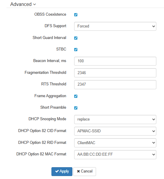
- OBSS Coexistence — automatic channel bandwidth reduction when the channel is loaded. When checked, the mode is enabled;
DFS Support — dynamic frequency selection mechanism. Requires wireless devices to scan the air and avoid using channels that overlap with those used by radar systems in the 5 GHz band:
Disabled — mechanism is disabled. DFS channels are not available for selection;
Enabled — mechanism is enabled;
- Forced — mechanism is disabled. DFS channels are available for selection.
- Short Guard Interval — support for Short Guard Interval. The device transmits data using 400 ns guard interval (instead of 800 ns) to remote devices which also support Short Guard Interval;
- STBC — Space-Time Block Coding method dedicated to improve data transmission reliability. When checked, the device transmits one data flow through several antennas. When unchecked, the device does not transmit the same data flow through several antennas;
- Beacon Interval, ms — beacon frames transmission period. The frames are sent to detect a remote device in the air. The parameter takes values from 20 to 2000 ms, by default: 100 ms;
- Fragmentation Threshold — frame fragmentation threshold, bytes. The parameter takes values 256–2346, by default: 2346;
- RTS Threshold — number of bytes over which the Request to Send will be sent. Decreasing this value may improve the performance of the device when there are a lot of connected remote devices. However this reduces general throughput of wireless network. The parameter takes values from 0 to 2347, by default: 2347;
- Frame Aggregation — enable support for AMPDU/AMSDU;
- Short Preamble — use of the packet short preamble;
- DHCP Snooping Mode — selection of DHCP option 82 processing policy. Available values for selection:
- ignore — option 82 processing is disabled. Default value;
- remove — device deletes the value of option 82;
- replace — device substitutes or replaces the value of option 82. When selecting this value to edit, the following parameters are opened:
- DHCP Option 82 CID format — replacement of the CID parameter value, can take values:
- APMAC-SSID — replacement of the CID parameter value to <MAC address of the device>-<SSID name>. Default value;
- SSID — replacement of the parameter value to device SSID name;
- custom — replacement of the CID parameter value to the value specified in the "DHCP Option 82 Custom CID";
- DHCP Option 82 Custom CID — an arbitrary string of up to 52 characters that will be passed to the CID. If the parameter value is not set, the device will change the CID to the default value — APMAC-SSID.
- DHCP Option 82 RID format — replacement of the RID parameter value, can take the following values:
- ClientMAC — change the RID content to the MAC address of the client device. Default value;
- APMAC — change the RID content to the MAC address of the device;
- APdomain — change the RID content to the domain in which the device is located;
- custom — change the RID content to the value specified in the "DHCP Option 82 Custom CID";
- Option 82 Unique RID — an arbitrary string of up to 63 characters that will be passed to the RID. If the parameter value is not set, the device will change the RID to the default value — ClientMAC.
- DHCP Option 82 MAC Format — selection of octet delimiters of the MAC address, which is transmitted in CID and RID:
- AA:BB:CC:DD:EE:FF — the delimiter is a colon (:). Default value;
- AA-BB-CC-DD-EE-FF — the delimiter is a dash (-).
- DHCP Option 82 CID format — replacement of the CID parameter value, can take values:
To apply a new configuration and save settings to non-volatile memory, click the "Apply" button. Click the "Cancel" button to discard the changes.
"QoS" submenu
The "QoS" submenu is used to configure Quality of Service functions.
- Wi-Fi Multimedia (WMM) — WMM (Wi-Fi Multimedia) support activation;
- Enable QoS — when checked, the setting of Quality of Service functions is available.
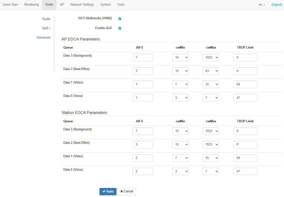
- AP EDCA parameters — device settings (traffic is transmitted to the client device):
- Queue — predefined queues for various kinds of traffic:
- Data 3 (Background) — low priority queue, high bandwidth (802.1p: cs1, cs2 priorities);
- Data 2 (Best Effort) — middle priority queue, middle bandwidth and delay. Most of the traditional IP data is sent to this queue (802.1p: cs0, cs3 priorities);
- Data 1 (Video) — high priority queue, minimal delay. In this queue, time-sensitive video data is automatically processed (802.1p: cs4, cs5 priorities);
- Data 0 (Voice) — high priority queue, minimal delay. In this queue, time sensitive data is automatically processed, such as: VoIP, streaming video (802.1p: cs6, cs7 priorities).
- AIFS — Arbitration Inter-Frame Spacing, defines the waiting time of data frames, measured in slots, takes values 1–255;
- cwMin — initial timeout value before resending a frame, specified in milliseconds, takes the values 1, 3, 7, 15, 31, 63, 127, 255, 511, 1023. The value of cwMin cannot exceed the value of cwMax;
- cwMax — maximum timeout value before resending a frame, specified in milliseconds, takes the values 1, 3, 7, 15, 31, 63, 127, 255, 511, 1023. The value of cwMax must exceed the value of cwMin;
- TXOP Limit — this parameter is used only for data transmitted from the client device. The transmission capability is the time interval, in milliseconds, when the remote WME station has the rights to initiate data transmission over the wireless medium to the device, the maximum value is 65535 milliseconds;
- Queue — predefined queues for various kinds of traffic:
- Station EDCA parameters — table of client device parameter settings (traffic is transmitted from the client device). For description of table fields, see above.
To apply a new configuration and save settings to non-volatile memory, click the "Apply" button. Click the "Cancel" button to discard the changes.
"Advanced" submenu
In the "Advanced” submenu, it is possible to configure advanced radio interface parameters of the device.
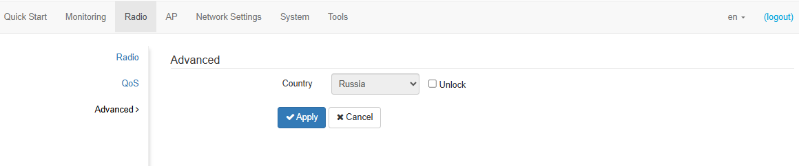
- Country — country of device operation. Select the "Unlock" checkbox to change a country. Depending on the selected value, the channel bandwidth and transmit power limit restrictions will be applied. The list of available frequency channels depends on the selected country, which affects the automatic channel selection in the Channel = Auto mode.
Local country regulations settings, including operation within legal frequency channels and output power, is the installer's responsibility.
Selecting the wrong region may result in compatibility issues with different client devices.
To apply a new configuration and save settings to non-volatile memory, click the "Apply" button. Click the "Cancel" button to discard the changes.
"AP" menu
In the "AP" menu, the access point (AP — Access Point) (hereinafter AP) can be configured.
The "AP" menu is only available when the device mode is "Access Point PTP" or "Access Point PMP".
"Access Point" submenu
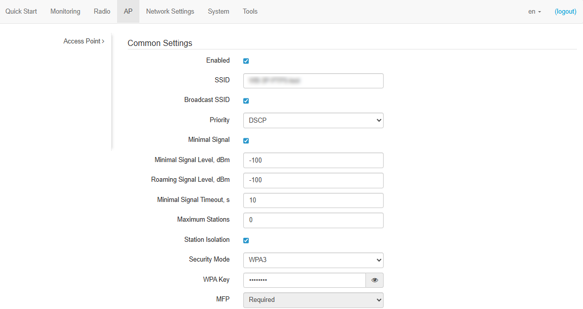
Common Settings:
- Enabled — when checked, the access point (AP) is enabled, otherwise it is disabled;
- SSID — virtual wireless network name;
- Broadcast SSID — when checked, broadcasting to the SSID is enabled, otherwise it is disabled;
- Priority — prioritization method. Defines the field based on which traffic transmitted to the radio interface will be distributed among WMM queues:
- DSCP — priority from the DSCP field of IP packet header will be analyzed;
- 802.1p — priority from the CoS (Class of Service) field of tagged packets will be analyzed.
- Minimal Signal — when checked, the function of disconnecting client devices at a low signal level (Minimal Signal) is enabled. For the functionality to work, the following parameters need to be configured:
- Minimal Signal Level, dBm — signal level, below which the client devices are disconnected from the wireless network;
- Roaming Signal Level, dBm — roaming sensitivity level, below which the client devices switch to another device. The parameter should be higher than the "Minimal Signal Level": if the "Minimal Signal Level" is -75 dBm, then the "Roaming Signal Level" should be, for example, -70 dBm;
- Minimal Signal Timeout, s — the period of time after which a decision is made to disconnect the client equipment from the wireless network.
- Maximum Stations — maximum number of client devices allowed to connect to the wireless network;
- Station Isolation — when checked, traffic isolation between connected devices is enabled;
- Security Mode — wireless network access security mode:
- Off — encryption for data transmission is not used;
- OWE (Opportunistic Wireless Encryption) — encryption method that ensures the security of data transmitted over an unsecured network. Users are not required to take any additional actions or enter a password to connect to the network;
- WPA2, WPA3 — encryption methods, when selecting one of the methods the following setting will be available:
- WPA Key — key/password required to connect to the wireless network. The key length is from 8 to 63 characters.
- WPA2-Enterprise, WPA3-Enterprise — wireless channel encryption mode, in which the device is authorized on the centralized RADIUS server. To configure these security modes, specify the parameters of the RADIUS server. Also specify a key for the RADIUS server. When selecting one of the these methods, the Radius setting will be available (see below).
- MFP — management frame protection (available in WPA2, WPA3, WPA2-Enterprise, and WPA3-Enterprise security modes. When WPA3, WPA3-Enterprise is selected, MFP is set to Required; when other security modes are selected, MFP is set to Not Required):
- Not Required — management frame protection is disabled;
- Capable — management frame protection works if the client supports MFP. The clients without MFP support can connect to this AP;
- Required — management frame protection is enabled. The clients that does not support MFP cannot connect to.
"Maximum Stations" and "Station Isolation" are available only in the "Access Point PMP" device mode.
If "Broadcast SSID" is disabled on the access point (AP), the client device will not be able to connect to it without additional configuration of the scanning mode. It is necessary to enable the active scanning mode on the client device (see Enabling active scanning).
RADIUS:
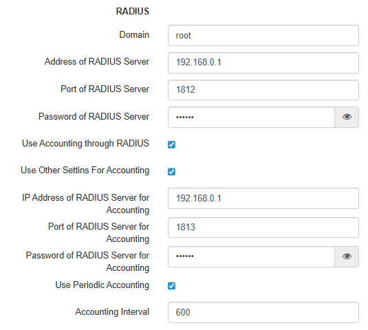
- Domain — user domain;
- Address of RADIUS Server — RADIUS server address;
- Port of RADIUS Server — port of RADIUS server that used for authentication and authorization;
- Password of RADIUS Server — password for RADIUS server used for authentication and authorization;
- Use Accounting through RADIUS — when checked, "Accounting" messages will be sent to the RADIUS server;
- Use Other Settings For Accounting:
- IP Address of RADIUS Server for Accounting — address of the RADIUS server, used for accounting;
- Password of RADIUS Server for Accounting — password for the RADIUS server used for accounting.
- Port of RADIUS Server for Accounting — port that will be used to collect accounts on the RADIUS server;
- Use Periodic Accounting — enable periodic sending of "Accounting" messages to the RADIUS server. The interval for sending messages can be set in the "Accounting Interval" field.
VLAN:
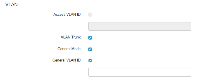
- Access VLAN ID — VLAN number from which the tag will be removed when transmitting traffic to client devices. When traffic passes in the opposite direction, untagged traffic from client devices will be tagged with a VLAN ID (available when VLAN Trunk mode is disabled);
- VLAN Trunk — when checked, tagged traffic is transmitted to client devices;
- General Mode — when checked, client devices are allowed to transmit untagged traffic together with tagged traffic (available when VLAN Trunk mode is enabled);
- General VLAN ID — VLAN number from which the tag will be removed when forwarding traffic to client devices. When passing traffic in the opposite direction, untagged traffic from client devices will be tagged with the General VLAN ID (available when VLAN Trunk and General Mode are enabled).
Shapers:
For "Access Point PTP" mode:
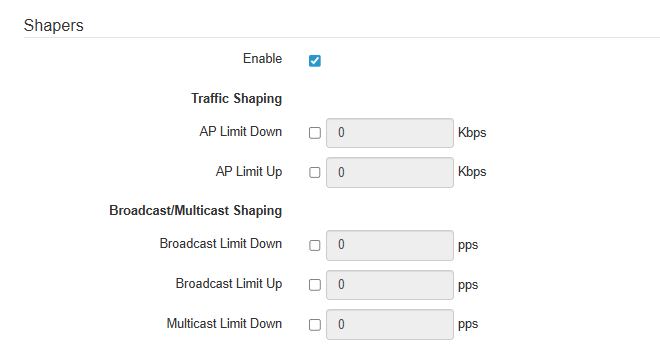
- Enable — activate the settings field;
- AP Limit Down — bandwidth limit in the direction from access point (AP) to client device, Kbps;
- AP Limit Up — bandwidth limit in the direction from client device to access point (AP), Kbps;
For "Access Point PMP" mode:
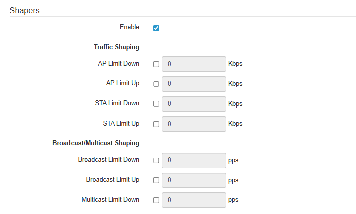
- Enable — activate the settings field;
- AP Limit Down — bandwidth limit in the direction from access point (AP) to client devices, Kbps;
- AP Limit Up — bandwidth limit in the direction from client devices to access point (AP), Kbps;
- STA Limit Down
- STA Limit Up
MAC ACL:
In this subsection, one can configure a list of MAC addresses of remote devices that are allowed or prohibited from connecting to this device, depending on the selected access policy.
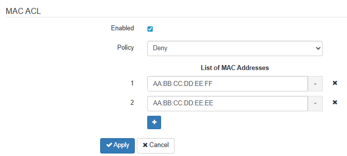
- Enabled — when checked, the selected access policy will work;
- Policy — access policy. Acceptable values:
- Deny — remote devices whose MAC addresses are on the list will be prohibited from connecting to this device. All other devices will be allowed access;
- Allow — only those remote devices whose MAC addresses are in the list will be allowed to connect to this device. All others will be denied access.
- List of MAC addresses — list of MAC addresses of remote devices that are allowed or denied access to this device. This list can contain up to 128 addresses.
To add an address to the list, click the  button and enter MAC address in the appeared field. To remove an address from the list, click the
  button in the corresponding line.
If there is a need to add the MAC address of a connected device to the list, click the  button at the end of the line and select the desired address from the list, it will automatically be added to the field.
By default, the list displays up to 10 addresses. To see the full list in case it contains more than 10 addresses, click the "Show all" button.
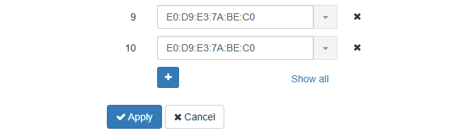
To apply a new configuration and save settings to non-volatile memory, click the "Apply" button. Click the "Cancel" button to discard the changes.
After changing the "SSID" on the access point "AP", access to client devices may be lost. First, change the "SSID" on client devices in the "STA" menu, and then on the access point (AP) in the "AP" menu.
"STA" menu
In the "STA" menu, the client (STA — Station) (hereinafter STA) can be configured.
The "STA" menu is only available in the "Station" device mode.
"Station" submenu
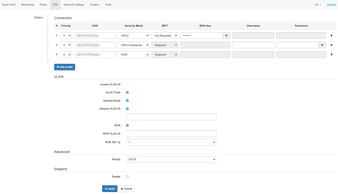
Connection:
- Priority — determines the order in which profiles are used. When searching for a network and connecting, the device uses the profile with the highest priority first. If the priorities are the same, then the device determines the order in which profiles are used based on the encryption mode and RSSI;
- SSID — virtual wireless network name;
- Security Mode — wireless network access security mode:
- Off — encryption for data transmission is not used;
- OWE (Opportunistic Wireless Encryption) — encryption method that ensures the security of data transmitted over an unsecured network;
- WPA2, WPA3 — encryption methods, when choosing one of the methods the following setting will be available:
- WPA Key — key/password required to connect to the wireless network. The key length is from 8 to 63 characters.
- WPA2-Enterprise, WPA3-Enterprise — wireless channel encryption mode, in which the device is authorized on the centralized RADIUS server. To configure these security modes, specify the connection parameters:
- Username — login required for authorization on the RADIUS server;
- Password — key/password required for authorization on the RADIUS server.
- MFP — management frame protection (available in WPA2, WPA3, WPA2-Enterprise, WPA3-Enterprise and OWE modes. When selecting the WPA3, WPA3-Enterprise, OWE security mode, MFP is set to the Required state, when selecting other security modes, MFP is set to the Not Required state):
- Not Required — management frame protection is disabled;
- Capable — management frame protection works if the wireless network supports MFP. The device can connect to a network that does not support MFP;
- Required — management frame protection is enabled. The device cannot connect to a wireless network that does not support MFP.
To add a new connection profile, click the "Add profile" button. You can add up to 8 profiles.
VLAN:
- Access VLAN ID — VLAN number from which the tag will be removed when forwarding traffic to Ethernet devices connected to the client (STA). When passing traffic in the opposite direction, untagged traffic will be tagged with VLAN ID (available when VLAN Trunk mode is disabled);
- VLAN Trunk — when checked, tagged traffic is transmitted to Ethernet devices connected to the client (STA);
- General Mode — when checked, Ethernet devices connected to the client (STA) are allowed to transmit untagged traffic with tagged traffic (available when VLAN Trunk mode is enabled);
- General VLAN ID — VLAN number from which the tag will be removed when transmitting traffic to Ethernet devices, connected to the client (STA). When traffic passes in the opposite direction, untagged traffic will be tagged with General VLAN ID (available when VLAN Trunk and General Mode are enabled);
- MVR — when checked, the MVR (Multicast VLAN Registration) functionality is enabled. Allows to use a separate VLAN for Multicast traffic;
- MVR VLAN ID — VLAN number of multicast traffic that will be untagged when transmitted to Ethernet devices connected to the client (STA). When traffic passes in the opposite direction, untagged IGMP packets from clients will be tagged with MVR VLAN ID;
Advanced:
- Priority — prioritization method. Defines the field based on which traffic transmitted to the radio interface will be distributed among WMM queues:
- DSCP — priority from the DSCP field of IP packet header will be analyzed;
- 802.1p — priority from the CoS (Class of Service) field of tagged packets will be analyzed.
Shapers:
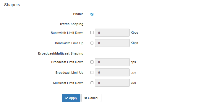
- Enable — activate the settings field;
- Bandwidth Limit Down — bandwidth limit in the direction from the client (STA) to the remote device, Kbps;
- Bandwidth Limit Up — bandwidth limit in the direction from remote device to client (STA), Kbps;
To apply a new configuration and save settings to non-volatile memory, click the "Apply" button. Click the "Cancel" button to discard the changes.
"Network Settings" menu
"System Configuration" submenu
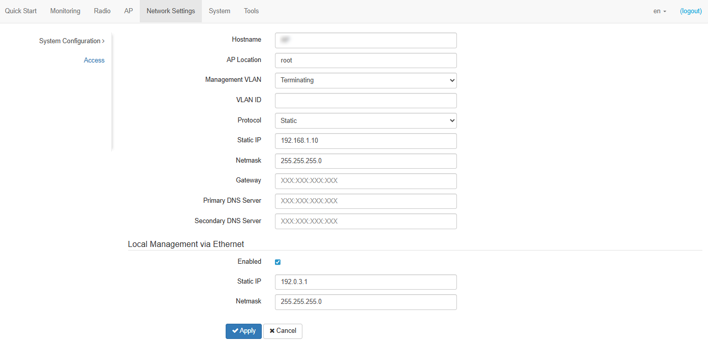
- Hostname — network name of the device, specified by string from 1 to 63 characters; Latin uppercase and lowercase letters, digits, hyphen “-” (hyphen can not be the last character in the name);
- AP Location — domain where the device is located;
- Management VLAN:
- Disabled — Management VLAN is not used;
- Terminating — mode in which the management VLAN is terminated at the device; in this case, remote devices connected via the radio interface do not have access to this VLAN;
- Forwarding — mode in which the management VLAN is also transmitted to the radio interface (with the appropriate AP configuration).
- VLAN ID — VLAN identifier used to access the device, takes values 1–4094;
- Protocol — select protocol for device connection via Ethernet interface to service provider network:
- DHCP — operating mode, when IP address, subnet mask, DNS server address, default gateway and other parameters required for operation are obtained from DHCP server automatically;
- Static — operating mode, when IP address and all the necessary parameters for WAN interface are assigned statically. If "Static" is selected, the following parameters will be available to set:
- Static IP — IP address of the device WAN interface in the provider network;
- Netmask — external subnet mask;
- Gateway — address, to which the packet is sent, if the route in routing table is not found for it.
- Primary DNS server, Secondary DNS server — IP addresses of DNS servers. If addresses of DNS servers are not automatically assigned via DHCP, set them manually.
After configuring the "Management VLAN", access to the device can be lost.
Local Management via Ethernet:
This subsection is used to configure untagged access to the device via the Ethernet interface.
- Enabled — activates the setting;
- Static IP — IP address of the device Ethernet interface in the local network (default 192.0.3.1);
- Network mask — subnet mask.
To apply a new configuration and save settings to non-volatile memory, click the "Apply" button. Click the "Cancel" button to discard the changes.
"Access" submenu
In the "Access" submenu, the access to the device via web interface, Telnet, SSH, NETCONF and SNMP can be configured.
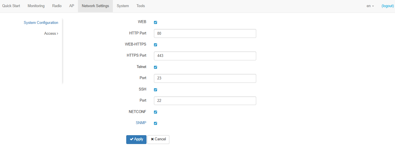
- To enable access to the device via the web interface via HTTP protocol, select the checkbox next to "WEB". In the window that appears, it is possible to change the HTTP port (by default: 80). The range of acceptable values of ports, in addition to the default, is from 1025 to 65535 inclusive;
- To enable access to the device via the web interface via HTTPS protocol, select the checkbox next to "WEB-HTTPS". In the window that appears, it is possible to change the HTTPS port (by default: 443). The range of acceptable values of ports, in addition to the default, is from 1025 to 65535 inclusive;
Note that the ports for the HTTP and HTTPS protocols should not have the same value.
- To enable access to the device via Telnet, select the checkbox next to "Telnet". In the window that appears, it is possible to change the Telnet port (23 by default). The range of acceptable port values, in addition to the default, is from 1025 to 65535 inclusive;
- To enable access to the device via SSH, select the checkbox next to "SSH". In the window that appears, it is possible to change the SSH port (22 by default). The range of acceptable port values, in addition to the default, is from 1025 to 65535 inclusive;
- To enable access to the device via NETCONF, select the checkbox next to "NETCONF".
The WB-3P-PTP5 software allows changing the device configuration, monitoring its status, as well as managing the device using the SNMP protocol.
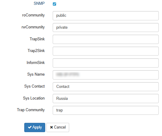
The device supports SNMPv1, SNMPv2, SNMPv3 protocols.
To change the SNMP settings, select the checkbox next to "SNMP", the following SNMP agent options become available:
- roCommunity — password to read the parameters (by default: public);
- rwCommunity — password to configure (write) parameters (by default: private);
- TrapSink — IP address or domain name of SNMPv1-trap message recipient in HOST [COMMUNITY [PORT]] format;
- Trap2Sink — IP address or domain name of SNMPv2-trap message recipient in HOST [COMMUNITY [PORT]] format;
- InformSink — IP address or domain name of Inform message recipient in HOST [COMMUNITY [PORT]] format;
- Sys Name — device name;
- Sys Contact — device vendor contact information;
- Sys Location — device location information;
- Trap community — password enclosed in traps (default value: trap).
The list of objects which are supported for reading and configuring via SNMP is given below:
- eltexLtd.1.127.1 — monitoring of device parameters;
- eltexLtd.1.127.3 — device management;
- eltexLtd.1.127.5 — device configuring.
where eltexLtd — 1.3.6.1.4.1.35265 is Eltex Enterprise ID.
To apply a new configuration and save settings to non-volatile memory, click "Apply”. Click "Cancel" to discard the changes.
"System" menu
In the "System" menu, the user can configure the system, time, syslog, change the password, upload/download the configuration, upgrade the firmware, and reboot the device.
"Device Firmware Upgrade" submenu
The "Device Firmware Upgrade" submenu is intended for upgrading the device firmware.
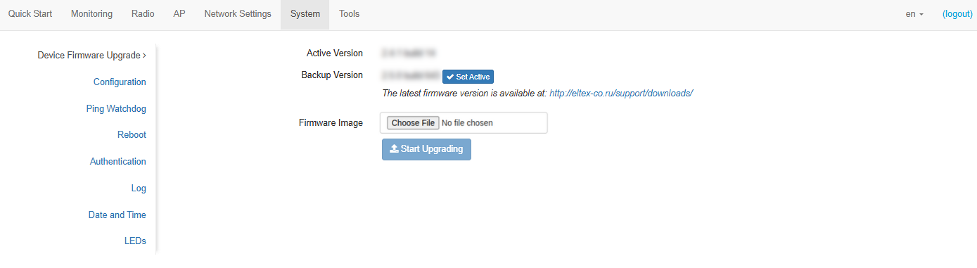
- Active Version — installed firmware version, which is operating at the moment;
- Backup version — installed firmware version that can be switched to without downloading a firmware file;
- Set active — button that allows making a backup version of the firmware active, this will require a device reboot. The active firmware version will not be set as a backup.
Firmware upgrade
Download the firmware file from http://eltex-co.com/support/downloads/ and save it on the PC. After that, click "Choose File" in the Firmware Image field and specify the path to the firmware file in .tar.gz format.
To start the update process, click the "Start Upgrading" button. The process may take several minutes (its current status will be shown on the page). The device will be automatically rebooted when the upgrade is completed.
The firmware should be upgraded first on the client (STA) and then on the access point (AP).
Do not switch off or reboot the device during a firmware upgrade.
"Configuration" submenu
In the "Configuration" submenu, the current configuration can be saved and updated.
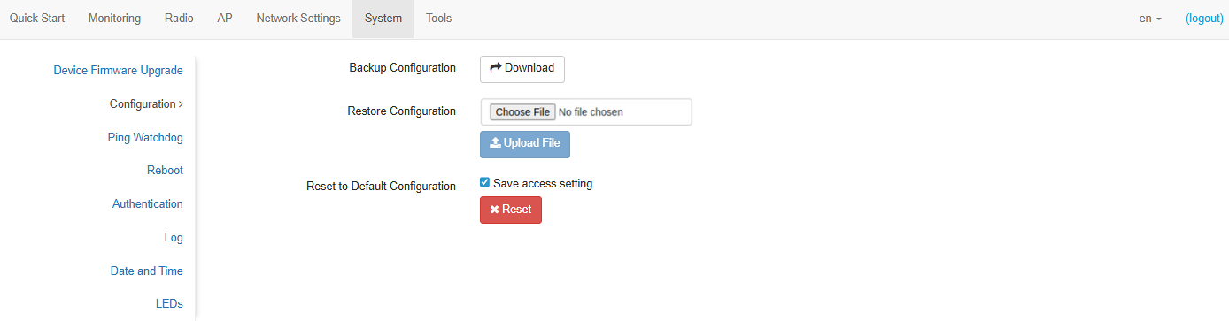
Backup Configuration
To save the current device configuration to local computer, click the "Download" button.
Restore Configuration
To upload the configuration file saved on the local computer, use the Restore Configuration item. To update the device configuration, click the "Chose File" button, specify a file (in .tar.gz format) and click the "Upload File" button. Uploaded configuration will be applied automatically and does not require device reboot.
Reset to Default Configuration
To reset all the settings to default values, click the "Reset" button. If the "Save access setting" checkbox is selected, then those configurations settings, that are responsible for access to the device (IP address settings, Telnet/SSH/SNMP/Netconf/Web access settings) will be saved.
"Ping Watchdog" submenu
The availability monitoring feature detects connectivity issues and reboots the device or its interfaces without user intervention. Restarting an interface also restarts the DHCP client on the current WAN interface.
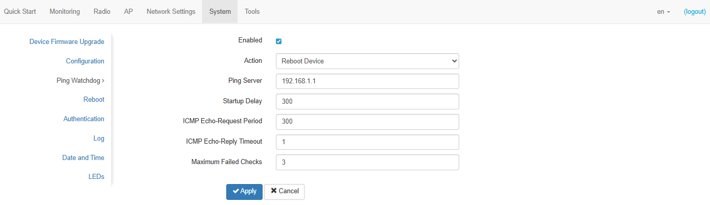
- Enabled — when checked, the ping watchdog feature is enabled, otherwise it is disabled;
- Action:
- Restart Ethernet Interface — if the specified Ping server is unavailable, the device Ethernet interface will restart;
- Restart Wireless Interface — if the specified Ping server is unavailable, the device wireless interface will restart;
- Reboot Device — if the specified Ping server is unavailable, the device will reboot.
- Ping Server — IP address or host domain name, where ICMP requests will be sent;
- Startup Delay — time in seconds after the device is powered on or the previous trigger, during which the availability monitoring will not operate. Acceptable values: 60–86400 inclusive;
- ICMP Echo-Request Period — time in seconds after which an ICMP request will be sent when receiving an ICMP reply or deciding that the previous ICMP request was unsuccessful. Acceptable values: 1–86400 inclusive;
- ICMP Echo-Reply Timeout — time in seconds during which an ICMP reply is expected after sending an ICMP request. If an ICMP reply is not received within this time, the ICMP request is considered unsuccessful. Acceptable values: 1–10 inclusive;
- Maximum Failed Checks — maximum number of failed ICMP requests. If the number of failed ICMP requests reaches the specified value, the designated action is performed. Acceptable values: 1–86400 inclusive.
To apply a new configuration and save settings to non-volatile memory, click "Apply”. Click "Cancel" to discard the changes.
"Reboot" submenu
To reboot the device, click the "Reboot" button. The device reboot process takes about 1 minute.
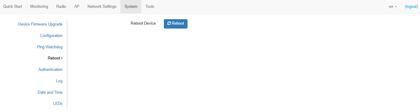
"Authentication" submenu
The "Authentication" submenu is used to configure user authentication.
Factory account for accessing the device: login: admin, password: password.
It's also possible to create additional accounts with administrator or viewer roles (configuration is only available through the CLI). Accounts with administrator role have full access to the device, including reading and writing all settings and full monitoring of the device's status. Accounts with viewer role can only monitor.
The "Local Password" section is used to change the factory password for admin account. This password is stored on this device. To change the password, enter the new password first in the "Password" field, then in the "Confirm Password" field.
The "RADIUS Authentication" section is designed to configure access parameters to the RADIUS server, which will be used to authenticate the user on this device.
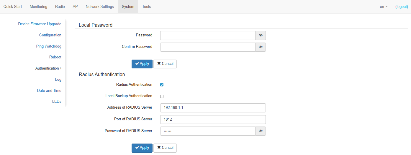
- Radius Authentication — when checked, authentication will be performed using the account on the RADIUS server;
- Local Backup Authentication — when checked, authentication using the local admin account is enabled if there is no connection to the RADIUS server;
- Address of RADIUS Server — IP address of the RADIUS server;
- Port of RADIUS Server — RADIUS server port used for authentication and authorization;
- Password of RADIUS Server — RADIUS server key used for authentication and authorization.
With the "Local Backup Authentication" option disabled, authorization performs only through the RADIUS server. If the RADIUS server is unavailable or the data is incorrect, authorization will fail.
With the "Local Backup Authentication" option enabled, if there is no connection with the RADIUS server, authorization can be performed using the local admin account. Authorization through other local accounts will not be performed.
For authentication through the RADIUS server, accounts with appropriate roles are created only on the server.
Accounts can be assigned the following roles:
admin — user with this role will have full access to configuring and monitoring the device;
viewer — user with this role will only have access to monitoring the device.
On the RADIUS server, the Cisco-AVPair = "shell:role=<role>" attribute is used to configure account roles (where <role> is either admin or viewer).
To apply a new configuration and save settings to non-volatile memory, click "Apply”. Click "Cancel" to discard the changes.
"Log" submenu
The "Log" submenu is designed to configure the output of various kinds of system debugging messages in order to detect problem causes in the device operation.
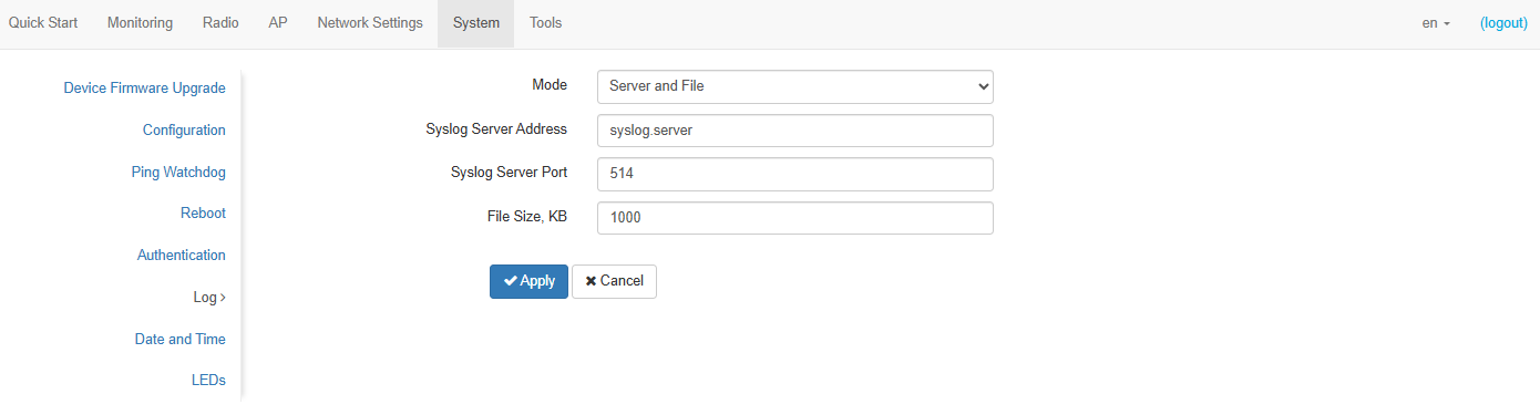
- Mode — Syslog agent operation mode:
- Local File — log information is stored in a local file and is available in the the "Events" submenu;
- Server and File — log information is sent to a remote Syslog server and stored in a local file.
- Syslog Server Address — IP address or domain name of the Syslog server;
- Syslog Server Port — port for incoming Syslog server messages (default: 514, acceptable values: from 1 to 65535);
- File Size, KB — maximum size of the log file (acceptable values: 1–1000 kB).
To apply a new configuration and save settings to non-volatile memory, click "Apply”. Click "Cancel" to discard the changes.
"Date and Time" submenu
In the "Date and Time" submenu, it is possible to set the time manually or using the time synchronization protocol (NTP).
Manual
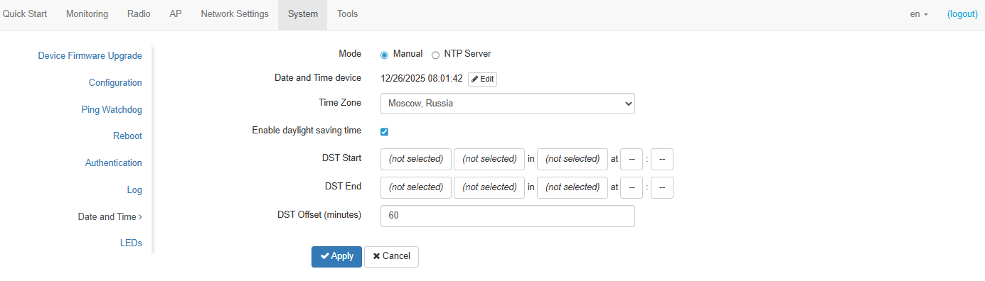
- Date and Time device — date and time on the device at the current moment. Click the "Edit" button to make corrections:
- Date, Time — set the current date and time or click the “Set current date and time” button to synchronize with the device;
- Time Zone — allows to set the time zone according to the nearest city for your region from the list;
- Enable daylight saving time — when selected, automatic daylight saving change will be performed automatically within the defined time period:
- DST Start — day and time, when daylight saving time starts;
- DST End — day and time, when daylight saving time ends;
- DST Offset (minutes) — time period in minutes, on which time offset is performing. The parameter can take a value from 0 to 720 minutes.
To apply a new configuration and save settings to non-volatile memory, click "Apply”. Click "Cancel" to discard the changes.
NTP Server
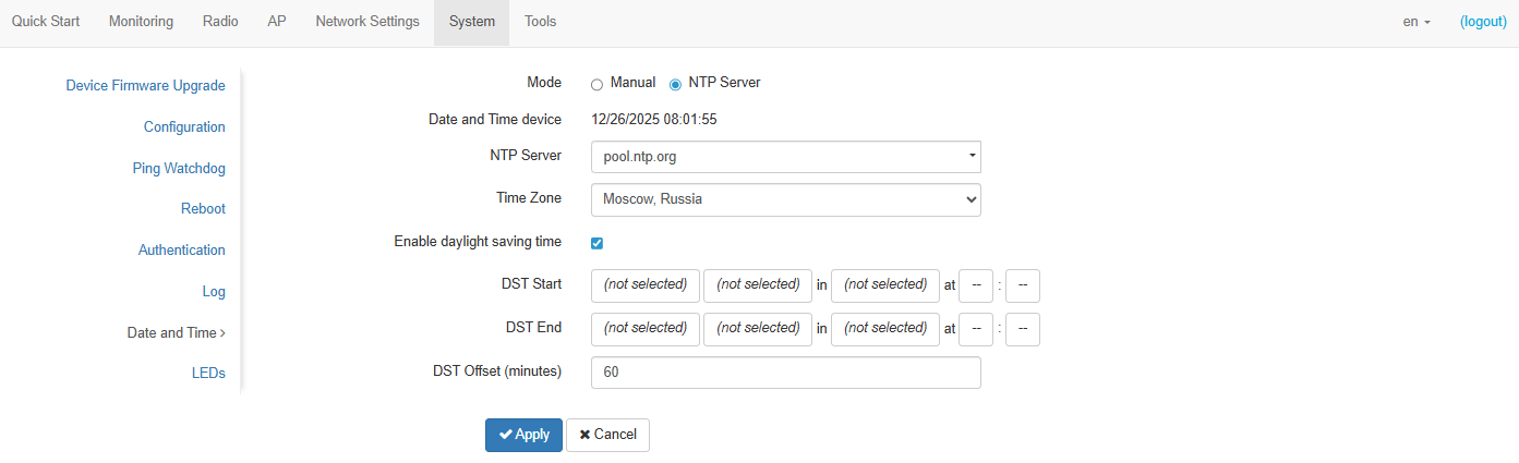
- Date and Time device — date and time set on the device;
- NTP Server — IP address/domain name of the time synchronization server. One can specify an address or select from an existing list;
- Time Zone — allows to set the time zone according to the nearest city for your region from the list;
- Enable daylight saving time — when selected, automatic daylight saving change will be performed automatically within the defined time period:
- DST Start — day and time, when daylight saving time starts;
- DST End — day and time, when daylight saving time ends;
- DST Offset (minutes) — time period in minutes, on which time offset is performing. The parameter can take a value from 0 to 720 minutes.
To apply a new configuration and save settings to non-volatile memory, click "Apply”. Click "Cancel" to discard the changes.
"LEDs" submenu
In the "LEDs" submenu, LEDs on the device can be customized.
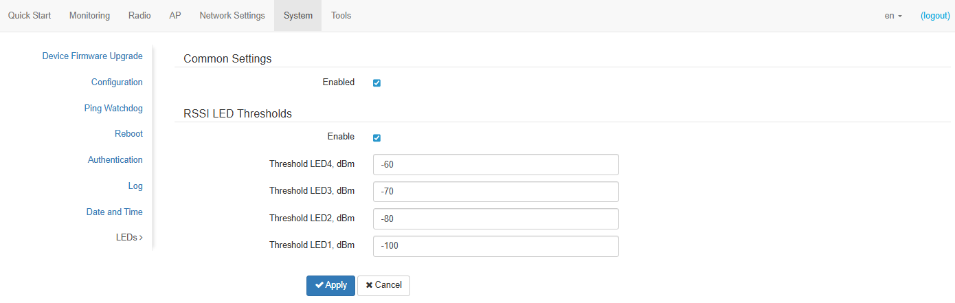
Common settings:
- Enabled — when checked, the indicators are enabled, otherwise they are disabled.
RSSI LED Threshold:
- Enable — when checked, the assignment of thresholds for each indicator is enabled, otherwise it is disabled;
- Threshold LED4, dBm — minimum signal level of a remote device (RSSI), at which LED4 turns on (by default: -60, acceptable values: -100–0);
- Threshold LED3, dBm — minimum signal level of a remote device (RSSI), at which LED3 turns on (by default: -70, acceptable values: -100–0);
- Threshold LED2, dBm — minimum signal level of a remote device (RSSI), at which LED2 turns on (by default: -80, acceptable values: -100–0);
- Threshold LED1, dBm — minimum signal level of a remote device (RSSI), at which LED1 turns on (by default: -100, acceptable values: -100–0).
To apply a new configuration and save settings to non-volatile memory, click "Apply”. Click "Cancel" to discard the changes.
"Tools" menu
"Antenna Align" submenu
Antenna alignment is the process of setting-up and fine-tuning the antenna to obtain the maximum signal.
To start the alignment, click the "Start" button.
To stop the alignment, click the "Stop" button.
Antenna Align:
- SSID — wireless network name;
- Channel — data transmission channel;
- RSSI — received signal level, dBm;
- Remote RSSI — received signal level of the remote device, dBm.
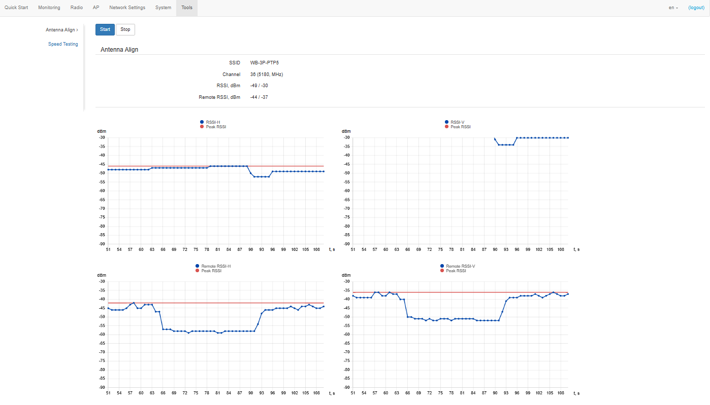
RSSI-H graph shows the change in signal level at the first antenna in dBm over time in seconds.
RSSI-V graph shows the change in signal level at the second antenna in dBm over time in seconds.
Remote RSSI-H graph shows the change in signal level at the first antenna of the remote device in dBm over time in seconds.
Remote RSSI-V graph shows the change in signal level at the second antenna of the remote device in dBm over time in seconds.
Peak RSSI — maximum signal level in dBm during the measurement period.
"Speed Testing" submenu
The "Speed Testing" submenu is designed to test the link speed.
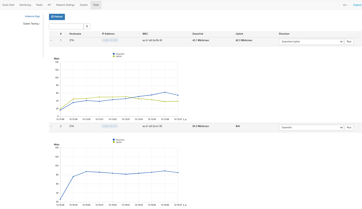
- Downlink — speed testing will be performed towards the remote device;
- Uplink — speed testing will be performed in the direction from the remote device;
- Downlink+Uplink — speed testing will be performed in turn in each direction.
The test is performed by TCP traffic and lasts 10 seconds for one direction. Only one remote device can run the test at a time.
To start, select the test direction and click the "Run" button. After the test is completed, the result will be displayed in the corresponding field and in the graph.
By default, the test uses VLAN 7 and subnet 192.0.4.0/24. If the network already uses such a subnet and VLAN, it is required to change the test settings so that they do not overlap with the existing networks. This can be done via the CLI. The process is described in more detail in the section "Perftest utility".
The following filters are available for searching the connected devices: by all fields, by hostname, by IP address, by MAC address. To select a filter, click . This functionality is only available in the Access Point PMP device mode.
Example of the device setup
This section provides an example of the initial setup of devices to organize a wireless bridge.
Figure 34 — WB-3P-PTP5 use case
In the browser address bar, enter the device IP address (by default 192.168.1.10, if the device has not received an address via DHCP). If the connection to the device is successful, a window will appear asking for login and password. Fill in the fields and click the "Log In" button. By default — login: admin, password: password.
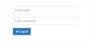
If this window does not appear, make sure that your PC is on the same network as the device.
Setting up an access point (AP):
- By default, WB-3P-PTP5 is configured to receive an address via DHCP. If the address has not been received, one can connect to the device using the factory IP address: 192.168.1.10, subnet mask: 255.255.255.0.
- It is necessary to update the device firmware to the latest version according to the section "Device Firmware Upgrade" submenu.
- In the Radio menu, perform preliminary configuration of the radio interface. Select the data transmission channel and specify the distance between the devices in kilometers.
- Save the settings by clicking the "Apply" button.
- In the AP menu, in the SSID field, specify the identifier of the wireless network which the client (STA) will connect to.
- In the "Security Mode" field, select the security mode by which authentication is performed on this network and specify the key if encrypted network is used.
- Save the settings by clicking the "Apply" button.
Setting up client (STA) to connect to an access point (AP):
- By default, WB-3P-PTP5 is configured to receive an address via DHCP. If the address has not been received, one can connect to the device using the factory IP address: 192.168.1.10, subnet mask: 255.255.255.0.
- It is necessary to update the device firmware to the latest version according to the section "Device Firmware Upgrade" submenu.
- If static or default settings are used to connect to the provider's network, then in the "Network settings" menu, in the "Protocol" field select "Static" and fill in the "Static IP", "Network mask", "Gateway" fields.
- In the STA menu, in the "SSID" field, specify the identifier of the wireless network which you want to connect to.
- In the "Security Mode" field, select the security mode by which authentication is performed on this network and specify the key if encrypted network is used.
- After clicking the "Apply" button, the client (STA) will search for the specified SSID in the air and, if found, will attempt to connect to the access point (AP) with the specified parameters.
- Check that the access point (AP) has appeared in the "Monitoring" menu in the "Wireless Peer" section. Check the availability of the access point (AP) by going to the device IP address in the browser address bar.
If all the steps described above are completed successfully, then the wireless connection between the devices is configured.
Managing the device using the command line
To enter configuration mode, issue the configure command.
To display the existing settings of a particular configuration section, issue the show-config command.
Press the key combination (English layout) — [Shift + ? ] to get a hint of what value this or that configuration parameter can take.
To get a list of options available for editing in this configuration section, press the Tab key.
To save the settings, enter the save command.
To go back to the previous configuration section, enter the exit command.
To exit configuration mode, enter the end command.
The setup should be started from the client device to avoid losing connection with it.
Connection to the device
By default, WB-3P-PTP5 is configured to receive the address via DHCP. If this does not happen, connect to the device using the factory IP address.
WB-3P-PTP5 factory default IP address: 192.168.1.10, subnet mask: 255.255.255.0.
Connection to the device is performed via SSH:
ssh admin@<IP address of the device>, then enter the password
Network parameters configuration
WB-3P-PTP5(root):/# configure
WB-3P-PTP5(config):/# interface
WB-3P-PTP5(config):/interface# br0
WB-3P-PTP5(config):/interface/br0# common
WB-3P-PTP5(config):/interface/br0/common# static-ip X.X.X.X (where X.X.X.X — device IP address)
WB-3P-PTP5(config):/interface/br0/common# netmask X.X.X.X (where X.X.X.X — subnet mask)
WB-3P-PTP5(config):/interface/br0/common# dns-server-1 X.X.X.X (where X.X.X.X — IP address of the dns server №1)
WB-3P-PTP5(config):/interface/br0/common# dns-server-2 X.X.X.X (where X.X.X.X — IP address of the dns server №2)
WB-3P-PTP5(config):/interface/br0/common# protocol static-ip (change operating mode from DHCP to Static-IP)
WB-3P-PTP5(config):/interface/br0/common# save (save changes)
Adding a static route
WB-3P-PTP5(config):/interface/br0/common# exit
WB-3P-PTP5(config):/interface/br0# exit
WB-3P-PTP5(config):/interface# exit
WB-3P-PTP5(config):/# route
WB-3P-PTP5(config):/route# default
WB-3P-PTP5(config):/route/default# destination X.X.X.X (where X.X.X.X — IP address of the network or destination node, for default route — 0.0.0.0)
WB-3P-PTP5(config):/route/default# netmask X.X.X.X (where X.X.X.X — destination network mask, for default route — 0.0.0.0)
WB-3P-PTP5(config):/route/default# gateway X.X.X.X (where X.X.X.X — gateway IP address)
WB-3P-PTP5(config):/interface/br0/common# save (save changes)
WB-3P-PTP5(root):/# configure
WB-3P-PTP5(config):/# interface
WB-3P-PTP5(config):/interface# br0
WB-3P-PTP5(config):/interface/br0# common
WB-3P-PTP5(config):/interface/br0/common# protocol dhcp (changing the operating mode from Static-IP to DHCP)
WB-3P-PTP5(config):/interface/br0/common# save (save changes)
Network parameters configuration via set-management-vlan-mode utility
Obtaining the network parameters via DHCP
WB-3P-PTP5(root):/# set-management-vlan-mode off protocol dhcp
Static settings
WB-3P-PTP5(root):/# set-management-vlan-mode off protocol static-ip ip-addr X.X.X.X netmask Y.Y.Y.Y gateway Z.Z.Z.Z (where X.X.X.X — static IP address, Y.Y.Y.Y — subnet mask, Z.Z.Z.Z — gateway)
Obtaining the network parameters via DHCP
WB-3P-PTP5(root):/# set-management-vlan-mode terminating vlan-id X protocol dhcp (where X — VLAN ID, used to access the device. Acceptable values: 1–4094)
Static settings
WB-3P-PTP5(root):/# set-management-vlan-mode terminating vlan-id X protocol static-ip ip-addr X.X.X.X netmask Y.Y.Y.Y gateway Z.Z.Z.Z (where X — VLAN ID, used to access the device. Acceptable values: 1–4094; X.X.X.X — static IP address; Y.Y.Y.Y — subnet mask, Z.Z.Z.Z — gateway)
Obtaining the network parameters via DHCP
WB-3P-PTP5(root):/# set-management-vlan-mode forwarding vlan-id X protocol dhcp (where X — VLAN ID, used to access the device. Acceptable values: 1–4094)
Static settings
WB-3P-PTP5(root):/# set-management-vlan-mode forwarding vlan-id X protocol static-ip ip-addr X.X.X.X netmask Y.Y.Y.Y gateway Z.Z.Z.Z (where X — VLAN ID, used to access the device. Acceptable values: 1–4094; X.X.X.X — static IP address; Y.Y.Y.Y — subnet mask, Z.Z.Z.Z — gateway)
WB-3P-PTP5(root):/# save (save changes)
Configuring 802.1p priority for Management VLAN
WB-3P-PTP5(root):/# configure
WB-3P-PTP5(config):/# interface
WB-3P-PTP5(config):/interface# management-vlan-terminating
WB-3P-PTP5(config):/interface/management-vlan-terminating# priority X (where X — 802.1p priority for management VLAN. Acceptable values: 0–7)
WB-3P-PTP5(config):/interface/management-vlan-terminating# save (save changes)
WB-3P-PTP5(root):/# configure
WB-3P-PTP5(config):/# interface
WB-3P-PTP5(config):/interface# management-vlan-forwarding
WB-3P-PTP5(config):/interface/management-vlan-forwarding# priority X (where X — 802.1p priority for management VLAN. Acceptable values: 0–7)
WB-3P-PTP5(config):/interface/management-vlan-forwarding# save (save changes)
Remote management configuration
WB-3P-PTP5(root):/# configure
WB-3P-PTP5(config):/# ssh
WB-3P-PTP5(config):/ssh# enable true (remote access management via SSH. To disable, enter false. By default: true)
WB-3P-PTP5(config):/ssh# port X (where Х — SSH server port. By default: 22)
WB-3P-PTP5(config):/ssh# save (save changes)
WB-3P-PTP5(root):/# configure
WB-3P-PTP5(config):/# telnet
WB-3P-PTP5(config):/telnet# enable true (remote access management via Telnet. To disable, enter false. By default: false)
WB-3P-PTP5(config):/telnet# port X (where Х — port. By default: 23)
WB-3P-PTP5(config):/telnet# save (save changes)
WB-3P-PTP5(root):/# configure
WB-3P-PTP5(config):/# snmp
WB-3P-PTP5(config):/snmp# enable true (SNMP management. To disable, enter false. By default: true)
WB-3P-PTP5(config):/snmp# rocommunity public (where public — password to read parameters)
WB-3P-PTP5(config):/snmp# rwcommunity private (where private — password to write parameters)
WB-3P-PTP5(config):/snmp# trapsink Х.Х.Х.Х (where Х.Х.Х.Х — IP address or domain name of the SNMPv1-trap message receiver in the format HOST [COMMUNITY [PORT]])
WB-3P-PTP5(config):/snmp# trap2sink Х.Х.Х.Х (where Х.Х.Х.Х — IP address or domain name of the SNMPv2-trap message receiver in the format HOST [COMMUNITY [PORT]])
WB-3P-PTP5(config):/snmp# informsink Х.Х.Х.Х (where Х.Х.Х.Х — IP address or domain name of the Inform message receiver in the format HOST [COMMUNITY [PORT]])
WB-3P-PTP5(config):/snmp# sysname WB-3P-PTP5 (where WB-3P-PTP5 — system name of the device. By default: WB-3P-PTP5)
WB-3P-PTP5(config):/snmp# syscontact Contact (where Contact — contact information of the device manufacturer. By default: Contact)
WB-3P-PTP5(config):/snmp# syslocation Russia (where Russia — device location information. By default: Russia)
WB-3P-PTP5(config):/snmp# trapcommunity trap (where trap — password contained in traps. By default: trap)
WB-3P-PTP5(config):/snmp# save (save changes)
WB-3P-PTP5(root):/# configure
WB-3P-PTP5(config):/# snmp
WB-3P-PTP5(config):/snmp# enable true (SNMP management. To disable, enter false. By default: true)
WB-3P-PTP5(config):/snmp# view (defines the range of OIDs available to specific user groups)
WB-3P-PTP5(config):/snmp/view# add inc-all
WB-3P-PTP5(config):/snmp/view# inc-all
WB-3P-PTP5(config):/snmp/view/inc-all# rule (defines access rights for different user groups to specific parts of the MIB)
WB-3P-PTP5(config):/snmp/view/inc-all/rule# add 1
WB-3P-PTP5(config):/snmp/view/inc-all/rule# 1
WB-3P-PTP5(config):/snmp/view/inc-all/rule/1# type included (where included — action type. Acceptable values: included — adding a given OID, excluded — excluding a given OID)
WB-3P-PTP5(config):/snmp/view/inc-all/rule/1# subtree .1 (where .1 — given OID. If the group uses view with type = included and OID .1 as read-view, then OID .1 and all its children will be available for reading. If type = excluded, then all OIDs will be available except .1 and its children)
WB-3P-PTP5(config):/snmp/view/inc-all/rule/1# exit
WB-3P-PTP5(config):/snmp/view/inc-all/rule# exit
WB-3P-PTP5(config):/snmp/view/inc-all# exit
WB-3P-PTP5(config):/snmp/view# exit
WB-3P-PTP5(config):/snmp# group (set OID ranges for reading and writing, determines the security level)
WB-3P-PTP5(config):/snmp/group# add rw (where rw — group name. Used to bind users to a group)
WB-3P-PTP5(config):/snmp/group# rw
WB-3P-PTP5(config):/snmp/group/rw# read-view inc-all (where inc-all — view to read parameters. Defines the range of OIDs available for reading)
WB-3P-PTP5(config):/snmp/group/rw# write-view inc-all (where inc-all — view to write parameters. Defines the range of OIDs available for writing)
WB-3P-PTP5(config):/snmp/group/rw# security-level priv (where priv — security level. Acceptable values: noauth — no security, auth — authorization of requests by username and password, priv — authorization of requests by username and password, as well as encryption of request and response)
WB-3P-PTP5(config):/snmp/group/rw# auth-type MD5 (where MD5 — authorization method. Acceptable values: MD5, SHA. It is used, if security-level = auth or priv. If not specified, then MD5 is used)
WB-3P-PTP5(config):/snmp/group/rw# priv-type DES (where DES — encryption method. Acceptable values: DES, AES. It is used, if security-level = priv. If not specified, then DES is used)
WB-3P-PTP5(config):/snmp/group/rw# exit
WB-3P-PTP5(config):/snmp/group# exit
WB-3P-PTP5(config):/snmp# user (user account. It is linked to a specific group and contains the name and passwords for authorization and encryption)
WB-3P-PTP5(config):/snmp/user# add admin (where admin — username. Used when authorizing requests, and can also be assigned for target)
WB-3P-PTP5(config):/snmp/user# admin
WB-3P-PTP5(config):/snmp/user/admin# group rw (where rw — group to which the user is added)
WB-3P-PTP5(config):/snmp/user/admin# auth-password password (where password — password for authorization. If the group security-level = auth or priv, and auth-password is not set, then the user will not be available)
WB-3P-PTP5(config):/snmp/user/admin# priv-password password (where password — password for encryption. If the group security-level = priv, and priv-password is not set, then the user will not be available)
WB-3P-PTP5(config):/snmp/user/admin# exit
WB-3P-PTP5(config):/snmp/user# exit
WB-3P-PTP5(config):/snmp# target (issue traps to specified hosts. Added optionally. Analog of trapsink and trap2sink for SNMPv3)
WB-3P-PTP5(config):/snmp/target# add target1
WB-3P-PTP5(config):/snmp/target# target1
WB-3P-PTP5(config):/snmp/target/target1# host Х.Х.Х.Х (where Х.Х.Х.Х — IP address of the host to which traps will be sent)
WB-3P-PTP5(config):/snmp/target/target1# port X (where Х — number of port to which the traps will be sent)
WB-3P-PTP5(config):/snmp/target/target1# user admin (where admin — user name used to issue traps. On the remote side, the user should be configured similarly. If an inactive user is specified (it does not have one of the required passwords set), then the target will also be inactive)
WB-3P-PTP5(config):/snmp/target/target1# exit
WB-3P-PTP5(config):/snmp/target# exit
WB-3P-PTP5(config):/snmp# snmpv3-only true (enable denying access to all OIDs via SNMPv1, SNMPv2. To disable, enter false. By default: false)
WB-3P-PTP5(config):/snmp# save (save changes)
IPv6 network parameters configuration
Access to the device via IPv6 protocol is disabled by default.
WB-3P-PTP5(root):/# configure
WB-3P-PTP5(config):/# interface
WB-3P-PTP5(config):/interface# br0
WB-3P-PTP5(config):/interface/br0# common
WB-3P-PTP5(config):/interface/br0/common# ipv6
WB-3P-PTP5(config):/interface/br0/common/ipv6# protocol dhcp (obtaining IPv6 network parameters via DHCP)
WB-3P-PTP5(config):/interface/br0/common/ipv6# enabled true (enabling access to the device via IPv6 protocol. To disable, enter false)
WB-3P-PTP5(config):/interface/br0/common/ipv6# save (save changes)
WB-3P-PTP5(root):/# configure
WB-3P-PTP5(config):/# interface
WB-3P-PTP5(config):/interface# br0
WB-3P-PTP5(config):/interface/br0# common
WB-3P-PTP5(config):/interface/br0/common# ipv6
WB-3P-PTP5(config):/interface/br0/common/ipv6# address XXXX:XXXX:XXXX:XXXX:XXXX:XXXX:XXXX:XXXX (where XXXX:XXXX:XXXX:XXXX:XXXX:XXXX:XXXX:XXXX — static IPv6 address of the device)
WB-3P-PTP5(config):/interface/br0/common/ipv6# address-prefix-length X (where X — static IPv6 address prefix. Takes values from 0 to 128. By default: 64)
WB-3P-PTP5(config):/interface/br0/common/ipv6# gateway XXXX:XXXX:XXXX:XXXX::/64 (IPv6 prefix is specified, for example 3211:0:0:1234::/64)
WB-3P-PTP5(config):/interface/br0/common/ipv6# dns-server-1 XXXX:XXXX:XXXX:XXXX:XXXX:XXXX:XXXX:XXXX/Y (where XXXX:XXXX:XXXX:XXXX:XXXX:XXXX:XXXX:XXXX/Y — IPv6 address of the DNS server №1 with prefix)
WB-3P-PTP5(config):/interface/br0/common/ipv6# dns-server-2 XXXX:XXXX:XXXX:XXXX:XXXX:XXXX:XXXX:XXXX/Y (where XXXX:XXXX:XXXX:XXXX:XXXX:XXXX:XXXX:XXXX/Y — IPv6 address of the DNS server №2 with prefix)
WB-3P-PTP5(config):/interface/br0/common/ipv6# protocol static-ip (enable use of static IPv6 networks parameters. For obtaining the IPv6 network parameters via DHCP enter dhcp)
WB-3P-PTP5(config):/interface/br0/common/ipv6# enabled true (enable access to the device via IPv6 protocol. To disable, enter false)
WB-3P-PTP5(config):/interface/br0/common/ipv6# save (save changes)
Radio settings
To change the radio channel, channel bandwidth, or power, use the following commands:
WB-3P-PTP5(root):/# configure
WB-3P-PTP5(config):/# interface
WB-3P-PTP5(config):/interface# wlan0
WB-3P-PTP5(config):/interface/wlan0# wlan
WB-3P-PTP5(config):/interface/wlan0/wlan# radio
WB-3P-PTP5(config):/interface/wlan0/wlan/radio# tx-power X (where X — power level in dBm)
WB-3P-PTP5(config):/interface/wlan0/wlan/radio# channel X (where X — number of the static channel on which the device will operate)
WB-3P-PTP5(config):/interface/wlan0/wlan/radio# bandwidth X (where X — channel bandwidth)
WB-3P-PTP5(config):/interface/wlan0/wlan/radio# save (save changes)
Lists of available channels
In 5 GHz Radio for locations "Russia (RU)"/"No restrictions (ALL)" the following channels are available for selection if DFS forced/auto:
- for 5, 10, 20 MHz channel bandwidth: 32, 33, 34, 35, 36, 37, 38, 39, 40, 41, 42, 43, 44, 45, 46, 47, 48, 49, 50, 51, 52, 53, 54, 55, 56, 57, 58, 59, 60, 61, 62, 63, 64, 65, 66, 67, 68, 69, 70, 71, 72, 73, 74, 75, 76, 77, 78, 79, 80, 81, 82, 83, 84, 85, 86, 87, 88, 89, 90, 91, 92, 93, 94, 95, 96, 97, 98, 99, 100, 101, 102, 103, 104, 105, 106, 107, 108, 109, 110, 111, 112, 113, 114, 115, 116, 117, 118, 119, 120, 121, 122, 123, 124, 125, 126, 127, 128, 129, 130, 131, 132, 133, 134, 135, 136, 137, 138, 139, 140, 141, 142, 143, 144, 145, 146, 147, 148, 149, 150, 151, 152, 153, 154, 155, 156, 157, 158, 159, 160, 161, 162, 163, 164, 165, 166, 167, 168, 169, 170, 171, 172, 173, 174, 175, 176, 177, 178, 179, 180, 181, 182, 183, 184, 185, 186, 187, 188, 189, 190, 191, 192, 193.
- for 40 MHz channel bandwidth:
- if "control-sideband" = lower: 36, 44, 52, 60, 68, 76, 84, 92, 100, 108, 116, 124, 132, 140, 149, 157, 165, 173, 181, 189.
- if "control-sideband" = upper: 40, 48, 56, 64, 72, 80, 88, 96, 104, 112, 120, 128, 136, 144, 153, 161, 169, 177, 185, 193.
- for 80 MHz : 36, 40, 44, 48, 52, 56, 60, 64, 68, 72, 76, 80, 84, 88, 92, 96, 100, 104, 108, 112, 116, 120, 124, 128, 132, 136, 140, 144, 149, 153, 157, 161, 165, 169, 173, 177, 181, 185, 189, 193.
- for 160 MHz : 36, 40, 44, 48, 52, 56, 60, 64, 68, 72, 76, 80, 84, 88, 92, 96, 100, 104, 108, 112, 116, 120, 124, 128, 149, 153, 157, 161, 165, 169, 173, 177.
In 5 GHz Radio for locations "Russia (RU)"/"No restrictions (ALL)" the following channels are available for selection if DFS forced/auto and fixed center frequency is enabled:
- for 20 MHz channel bandwidth: 32, 33, 34, 35, 36, 37, 38, 39, 40, 41, 42, 43, 44, 45, 46, 47, 48, 49, 50, 51, 52, 53, 54, 55, 56, 57, 58, 59, 60, 61, 62, 63, 64, 65, 66, 67, 68, 69, 70, 71, 72, 73, 74, 75, 76, 77, 78, 79, 80, 81, 82, 83, 84, 85, 86, 87, 88, 89, 90, 91, 92, 93, 94, 95, 96, 97, 98, 99, 100, 101, 102, 103, 104, 105, 106, 107, 108, 109, 110, 111, 112, 113, 114, 115, 116, 117, 118, 119, 120, 121, 122, 123, 124, 125, 126, 127, 128, 129, 130, 131, 132, 133, 134, 135, 136, 137, 138, 139, 140, 141, 142, 143, 144, 145, 146, 147, 148, 149, 150, 151, 152, 153, 154, 155, 156, 157, 158, 159, 160, 161, 162, 163, 164, 165, 166, 167, 168, 169, 170, 171, 172, 173, 174, 175, 176, 177, 178, 179, 180, 181, 182, 183, 184, 185, 186, 187, 188, 189, 190, 191, 192, 193.
- for 40 MHz channel bandwidth: 34, 35, 36, 37, 38, 39, 40, 41, 42, 43, 44, 45, 46, 47, 48, 49, 50, 51, 52, 53, 54, 55, 56, 57, 58, 59, 60, 61, 62, 63, 64, 65, 66, 67, 68, 69, 70, 71, 72, 73, 74, 75, 76, 77, 78, 79, 80, 81, 82, 83, 84, 85, 86, 87, 88, 89, 90, 91, 92, 93, 94, 95, 96, 97, 98, 99, 100, 101, 102, 103, 104, 105, 106, 107, 108, 109, 110, 111, 112, 113, 114, 115, 116, 117, 118, 119, 120, 121, 122, 123, 124, 125, 126, 127, 128, 129, 130, 131, 132, 133, 134, 135, 136, 137, 138, 139, 140, 141, 142, 143, 144, 145, 146, 147, 148, 149, 150, 151, 152, 153, 154, 155, 156, 157, 158, 159, 160, 161, 162, 163, 164, 165, 166, 167, 168, 169, 170, 171, 172, 173, 174, 175, 176, 177, 178, 179, 180, 181, 182, 183, 184, 185, 186, 187, 188, 189, 190, 191.
- for 80 MHz channel bandwidth: 38, 39, 40, 41, 42, 43, 44, 45, 46, 47, 48, 49, 50, 51, 52, 53, 54, 55, 56, 57, 58, 59, 60, 61, 62, 63, 64, 65, 66, 67, 68, 69, 70, 71, 72, 73, 74, 75, 76, 77, 78, 79, 80, 81, 82, 83, 84, 85, 86, 87, 88, 89, 90, 91, 92, 93, 94, 95, 96, 97, 98, 99, 100, 101, 102, 103, 104, 105, 106, 107, 108, 109, 110, 111, 112, 113, 114, 115, 116, 117, 118, 119, 120, 121, 122, 123, 124, 125, 126, 127, 128, 129, 130, 131, 132, 133, 134, 135, 136, 137, 138, 139, 140, 141, 142, 143, 144, 145, 146, 147, 148, 149, 150, 151, 152, 153, 154, 155, 156, 157, 158, 159, 160, 161, 162, 163, 164, 165, 166, 167, 168, 169, 170, 171, 172, 173, 174, 175, 176, 177, 178, 179, 180, 181, 182, 183, 184, 185, 186, 187.
- for 160 MHz channel bandwidth: 46, 47, 48, 49, 50, 51, 52, 53, 54, 55, 56, 57, 58, 59, 60, 61, 62, 63, 64, 65, 66, 67, 68, 69, 70, 71, 72, 73, 74, 75, 76, 77, 78, 79, 80, 81, 82, 83, 84, 85, 86, 87, 88, 89, 90, 91, 92, 93, 94, 95, 96, 97, 98, 99, 100, 101, 102, 103, 104, 105, 106, 107, 108, 109, 110, 111, 112, 113, 114, 115, 116, 117, 118, 119, 120, 121, 122, 123, 124, 125, 126, 127, 128, 129, 130, 131, 132, 133, 134, 135, 136, 137, 138, 139, 140, 141, 142, 143, 144, 145, 146, 147, 148, 149, 150, 151, 152, 153, 154, 155, 156, 157, 158, 159, 160, 161, 162, 163, 164, 165, 166, 167, 168, 169, 170, 171, 172, 173, 174, 175, 176, 177, 178, 179.
In 5 GHz Radio for locations "Russia (RU)"/"No restrictions (ALL)" the following channels are available for selection if DFS disabled:
- for 5, 10, 20 MHz channel bandwidth: 32, 33, 34, 35, 36, 37, 38, 39, 40, 41, 42, 43, 44, 45, 46, 47, 48, 148, 149, 150, 151, 152, 153, 154, 155, 156, 157, 158, 159, 160, 161, 162, 163, 164, 165, 166, 167, 168, 169, 170, 171, 172, 173, 174, 175, 176, 177, 178, 179, 180, 181, 182, 183, 184, 185, 186, 187, 188, 189, 190, 191, 192, 193.
- for 40 MHz channel bandwidth:
- if "control-sideband" = lower: 36, 44, 149, 157, 165, 173, 181, 189.
- if "control-sideband" = upper: 40, 48, 153, 161, 169, 177, 185, 193.
- for 80 MHz channel bandwidth: 36, 40, 44, 48, 149, 153, 157, 161, 165, 169, 173, 177, 181, 185, 189, 193.
- for 160 MHz channel bandwidth: 149, 153, 157, 161, 165, 169, 173, 177.
In 5 GHz Radio for locations "Russia (RU)"/"No restrictions (ALL)" the following channels are available for selection if DFS disabled and fixed center frequency is enabled:
- for 20 MHz channel bandwidth: 32, 33, 34, 35, 36, 37, 38, 39, 40, 41, 42, 43, 44, 45, 46, 47, 48, 148, 149, 150, 151, 152, 153, 154, 155, 156, 157, 158, 159, 160, 161, 162, 163, 164, 165, 166, 167, 168, 169, 170, 171, 172, 173, 174, 175, 176, 177, 178, 179, 180, 181, 182, 183, 184, 185, 186, 187, 188, 189, 190, 191, 192, 193.
- for 40 MHz channel bandwidth: 34, 35, 36, 37, 38, 39, 40, 41, 42, 43, 44, 45, 46, 150, 151, 152, 153, 154, 155, 156, 157, 158, 159, 160, 161, 162, 163, 164, 165, 166, 167, 168, 169, 170, 171, 172, 173, 174, 175, 176, 177, 178, 179, 180, 181, 182, 183, 184, 185, 186, 187, 188, 189, 190, 191.
- for 80 MHz channel bandwidth: 38, 39, 40, 41, 42, 154, 155, 156, 157, 158, 159, 160, 161, 162, 163, 164, 165, 166, 167, 168, 169, 170, 171, 172, 173, 174, 175, 176, 177, 178, 179, 180, 181, 182, 183, 184, 185, 186, 187.
- for 160 MHz channel bandwidth: 162, 163, 164, 165, 166, 167, 168, 169, 170, 171, 172, 173, 174, 175, 176, 177, 178, 179.
Advanced Radio settings
WB-3P-PTP5(config):/interface/wlan0/wlan/radio# country X (parameter X can take a value: RU, ALL)
WB-3P-PTP5(config):/interface/wlan0/wlan/radio# work-mode X (where X — radio interface operating mode according to the IEEE 802.11 standard. Acceptable values: anacax, anac, ax)
WB-3P-PTP5(config):/interface/wlan0/wlan/radio# control-sideband lower (parameter can take a value: lower, upper. By default: lower)
WB-3P-PTP5(config):/interface/wlan0/wlan/radio# center-frequency true (enable fixed center frequency. To disable, enter false)
WB-3P-PTP5(config):/interface/wlan0/wlan/radio# sgi true (enable the use of a Short Guard Interval for data transmission of 400 ns instead of 800 ns. To disable, enter false)
WB-3P-PTP5(config):/interface/wlan0/wlan/radio# use-limit-channels true (enable the use of limited list of channels. To disable, enter false)
WB-3P-PTP5(config):/interface/wlan0/wlan/radio# limit-channels '50 51 52 (where 50 51 52 — are channels of range in which the configurable radio interface can operate)
Configuration is performed only for Radio 5 GHz
WB-3P-PTP5(config):/interface/wlan1/wlan/radio# dfs X (where X — DFS operating mode. Acceptable values: forced — DFS is disabled, DFS channels are available for selection; auto — DFS is enabled; disabled — DFS is disabled, DFS channels are not available for selection)
WB-3P-PTP5(config):/interface/wlan0/wlan/radio# stbc true (enable the space-time block coding (STBC) method, which is aimed at increasing the reliability of data transmission. To disable, enter false)
WB-3P-PTP5(config):/interface/wlan0/wlan/radio# aggregation true (enable aggregation on Radio — support for AMPDU/AMSDU. To disable, enter false)
WB-3P-PTP5(config):/interface/wlan0/wlan/radio# short-preamble true (enable the short packet preamble. To disable, enter false)
WB-3P-PTP5(config):/interface/wlan0/wlan/radio# enable-fixed-rate true (enable fixed channel transfer rate. To disable, enter false)
WB-3P-PTP5(config):/interface/wlan0/wlan/radio# maximal-rate-tx
WB-3P-PTP5(config):/interface/wlan0/wlan/radio/maximal-rate-tx# he X (where X — modulation name in capital letters without spaces, for example, NSS2-MCS11. The parameter is used when connecting devices in IEEE 802.11ax mode)
WB-3P-PTP5(config):/interface/wlan0/wlan/radio/maximal-rate-tx# vht X (where X — modulation name in capital letters without spaces, for example, NSS2-MCS11. The parameter is used when connecting devices in IEEE 802.11ac mode)
WB-3P-PTP5(config):/interface/wlan0/wlan/radio/maximal-rate-tx# ht X (where X — modulation name in capital letters without spaces, for example, MCS15. The parameter is used when connecting devices in IEEE 802.11n mode)
WB-3P-PTP5(config):/interface/wlan0/wlan/radio/maximal-rate-tx# legacy X (where X — modulation name in capital letters without spaces, for example, OFDM54. The parameter is used when connecting devices in IEEE 802.11a mode)
WB-3P-PTP5(config):/interface/wlan0/wlan/radio/maximal-rate-tx# enable true (enable maximal transmit rate. To disable, enter false)
WB-3P-PTP5(config):/interface/wlan0/wlan/radio/qos# save (save changes)
WB-3P-PTP5(config):/interface/wlan0/wlan/radio# maximal-rate-rx
WB-3P-PTP5(config):/interface/wlan0/wlan/radio/maximal-rate-rx# he X (where X — modulation name in capital letters without spaces, for example, NSS2-MCS11. The parameter is used when connecting devices in IEEE 802.11ax mode)
WB-3P-PTP5(config):/interface/wlan0/wlan/radio/maximal-rate-rx# vht X (where X — modulation name in capital letters without spaces, for example, NSS2-MCS11. The parameter is used when connecting devices in IEEE 802.11ac mode)
WB-3P-PTP5(config):/interface/wlan0/wlan/radio/maximal-rate-rx# ht X (where X — modulation name in capital letters without spaces, for example, MCS15. The parameter is used when connecting devices in IEEE 802.11n mode)
WB-3P-PTP5(config):/interface/wlan0/wlan/radio/maximal-rate-rx# legacy X (where X — modulation name in capital letters without spaces, for example, OFDM54. The parameter is used when connecting devices in IEEE 802.11a mode)
WB-3P-PTP5(config):/interface/wlan0/wlan/radio/maximal-rate-rx# enable true (enable maximal receive rate. To disable, enter false. Available only for ap-ptp and sta modes)
WB-3P-PTP5(config):/interface/wlan0/wlan/radio/qos# save (save changes)
WB-3P-PTP5(config):/interface/wlan0/wlan/radio# minimal-rate-tx
WB-3P-PTP5(config):/interface/wlan0/wlan/radio/minimal-rate-tx# he X (where X — modulation name in capital letters without spaces, for example, NSS1-MCS0. The parameter is used when connecting devices in IEEE 802.11ax mode)
WB-3P-PTP5(config):/interface/wlan0/wlan/radio/minimal-rate-tx# vht X (where X — modulation name in capital letters without spaces, for example, NSS1-MCS0. The parameter is used when connecting devices in IEEE 802.11ac mode)
WB-3P-PTP5(config):/interface/wlan0/wlan/radio/minimal-rate-tx# ht X (where X — modulation name in capital letters without spaces, for example, MCS0. The parameter is used when connecting devices in IEEE 802.11n mode)
WB-3P-PTP5(config):/interface/wlan0/wlan/radio/minimal-rate-tx# legacy X (where X — modulation name in capital letters without spaces, for example, OFDM6. The parameter is used when connecting devices in IEEE 802.11a mode)
WB-3P-PTP5(config):/interface/wlan0/wlan/radio/minimal-rate-tx# enable true (enable minimal transmit rate. To disable, enter false)
WB-3P-PTP5(config):/interface/wlan0/wlan/radio/qos# save (save changes)
WB-3P-PTP5(config):/interface/wlan0/wlan/radio# minimal-rate-rx
WB-3P-PTP5(config):/interface/wlan0/wlan/radio/minimal-rate-rx# he X (where X — modulation name in capital letters without spaces, for example, NSS1-MCS0. The parameter is used when connecting devices in IEEE 802.11ax mode)
WB-3P-PTP5(config):/interface/wlan0/wlan/radio/minimal-rate-rx# vht X (where X — modulation name in capital letters without spaces, for example, NSS1-MCS0. The parameter is used when connecting devices in IEEE 802.11ac mode)
WB-3P-PTP5(config):/interface/wlan0/wlan/radio/minimal-rate-rx# ht X (where X — modulation name in capital letters without spaces, for example, MCS0. The parameter is used when connecting devices in IEEE 802.11n mode)
WB-3P-PTP5(config):/interface/wlan0/wlan/radio/minimal-rate-rx# legacy X (where X — modulation name in capital letters without spaces, for example, OFDM6. The parameter is used when connecting devices in IEEE 802.11a mode)
WB-3P-PTP5(config):/interface/wlan0/wlan/radio/minimal-rate-rx# enable true (enable the minimal receive rate. To disable it, enter false. Available only for ap-ptp and sta modes)
WB-3P-PTP5(config):/interface/wlan0/wlan/radio/qos# save (save changes)
The maximal and minimal receive rate parameters are used to specify the maximal and minimal transmit rate to a remote device.
Therefore, when configuring maximal and/or minimal receive rate, for example, on a client (STA), there is no need to configure maximal and/or minimal transmit rate on an access point (AP).
WB-3P-PTP5(config):/interface/wlan0/wlan/radio# auto-distance true (enable automatic distance calculation between devices. To disable, enter false)
WB-3P-PTP5(config):/interface/wlan0/wlan/radio# max-distance X (where X — distance between devices in kilometers. The parameter is used when auto-distance is disabled. Acceptable values: 0–34. By default: 0)
WB-3P-PTP5(config):/interface/wlan0/wlan/radio/tdd# enable true (enable collision-free time-division access technology, which synchronizes data transmission in both directions within a time frame. To disable, enter false)
WB-3P-PTP5(config):/interface/wlan0/wlan/radio/tdd# tx-ratio X (where X — percentage of a timeslot in a TDD frame allocated for transmitting Downlink traffic. Acceptable values: 10, 20, 30, 40, 50, 60, 70, 80, 90. By default: 50)
WB-3P-PTP5(config):/interface/wlan0/wlan/radio/tdd# frame-length X (where X — TDD frame duration in milliseconds. Acceptable values: 5, 10. By default: 10)
WB-3P-PTP5(config):/interface/wlan0/wlan/radio/qos# save (save changes)
WB-3P-PTP5(config):/interface/wlan0/wlan/radio# dtim-interval X (where X — DTIM interval. Acceptable values: 1–255. By default: 64)
WB-3P-PTP5(config):/interface/wlan0/wlan/radio# qos
WB-3P-PTP5(config):/interface/wlan0/wlan/radio/qos# enable true (when this option is enabled, the EDCA parameters specified in the configuration are applied. To disable it, enter false)
WB-3P-PTP5(config):/interface/wlan0/wlan/radio/qos# edca-ap (configuring device QoS parameters (traffic is transmitted towards the client device)))
WB-3P-PTP5(config):/interface/wlan0/wlan/radio/qos/edca-ap# bk (configuring EDCA parameters for low-priority queue (802.1p priorities: cs1, cs2))
WB-3P-PTP5(config):/interface/wlan0/wlan/radio/qos/edca-ap/bk# aifs X (where X — waiting time for frames of data, measured in slots. Acceptable values: 1–255)
WB-3P-PTP5(config):/interface/wlan0/wlan/radio/qos/edca-ap/bk# cwmin X (where X — initial timeout value before resending a frame, specified in milliseconds. Acceptable values: 1, 3, 7, 15, 31, 63, 127, 255, 511, 1023. The cwMin value cannot exceed the cwMax value)
WB-3P-PTP5(config):/interface/wlan0/wlan/radio/qos/edca-ap/bk# cwmax X (where X — maximum timeout value before resending a frame, specified in milliseconds. Acceptable values: 1, 3, 7, 15, 31, 63, 127, 255, 511, 1023. The cwMax value should be greater than the cwMin value)
WB-3P-PTP5(config):/interface/wlan0/wlan/radio/qos/edca-ap/bk# txop X (where X — time interval, in milliseconds, during which a WME station is allowed to initiate data transmission over wireless medium to the device. Maximum value is 65535 milliseconds)
WB-3P-PTP5(config):/interface/wlan0/wlan/radio/qos/edca-ap/bk# exit
WB-3P-PTP5(config):/interface/wlan0/wlan/radio/qos/edca-ap# exit
WB-3P-PTP5(config):/interface/wlan0/wlan/radio/qos# edca-sta (configuring QoS parameters of a client device (traffic is transmitted from a client device))
WB-3P-PTP5(config):/interface/wlan0/wlan/radio/qos# save (save changes)
The configuration method of edca-sta is the same as that of edca-ap.
Parameters configuration for queues be, vi, vo is similar to parameters configuration for queue bk.
WB-3P-PTP5(config):/interface/wlan0/wlan/radio# force-passive-scan false (enable active scanning mode. To disable, enter true. By default: true)
After enabling active scanning, the client device starts sending Probe Request packets to all available channels to search for a network. This may create additional load on the air.
Configuring DHCP option 82
DHCP snooping operating modes:
- ignore – option 82 processing is disabled. Default value;
- replace – device substitutes or replaces the value of option 82;
- remove – device removes the value of option 82.
WB-3P-PTP5(root):/# configure
WB-3P-PTP5(config):/# interface
WB-3P-PTP5(config):/interface# wlan0
WB-3P-PTP5(config):/interface/wlan0# common
WB-3P-PTP5(config):/interface/wlan0/common# dhcp-snooping
WB-3P-PTP5(config):/interface/wlan0/common/dhcp-snooping# dhcp-snooping-mode replace (selection of DHCP snooping operation in the mode of replacement or substitution of option 82)
WB-3P-PTP5(config):/interface/wlan0/common/dhcp-snooping# save (save changes)
If on the radio interface, the 82 option processing policy is configured to replace, the following parameters become available for configuration:
WB-3P-PTP5(config):/interface/wlan0/common/dhcp-snooping# dhcp-option-82-CID-format custom (where custom — replacement of the CID content with the value specified in the dhcp-option-82-customCID parameter. The parameter can take values: APMAC-SSID — replacement of the CID content with <MAC address of the device>-<SSID name>. SSID — replacement of the CID content with SSID name. By default: APMAC-SSID)
WB-3P-PTP5(config):/interface/wlan0/common/dhcp-snooping# dhcp-option-82-RID-format custom (where custom — replacement of the RID content with the value specified in the dhcp-option-82-custom-RID parameter. The parameter can take values: ClientMAC — replacement of the RID content with MAC address of the client device. APMAC —replacement of the RID content with MAC address of the device. APdomain — replacement of the RID content with the domain where the device is located. By default: ClientMAC)
WB-3P-PTP5(config):/interface/wlan0/common/dhcp-snooping# dhcp-option-82-custom-CID longstring (where longstring — value from 1 to 52 characters, which will be transmitted in CID. If the value of dhcp-option-82-custom-CID parameter is not defined, the device will change the CID to the default value: <MAC address of the device>-<SSID name>)
WB-3P-PTP5(config):/interface/wlan0/common/dhcp-snooping# dhcp-option-82-custom-RID longstring (where longstring — value from 1 to 63 characters, which will be transmitted in RID. If the value of dhcp-option-82-custom-RID parameter is not defined, the device will change the RID to the default value: <MAC address of the client device>)
WB-3P-PTP5(config):/interface/wlan0/common/dhcp-snooping# dhcp-option-82-MAC-format radius (selecting octet delimiter of the MAC address which is transmitted in RID and CID. radius — a dash is used as a delimiter: AA-BB-CC-DD-EE-FF; default — a colon is used as a delimiter: AA:BB:CC:DD:EE:FF)
WB-3P-PTP5(config):/interface/wlan0/common/dhcp-snooping# save (save changes)
Configuring wireless network
Table 6 — Commands for configuring device operating mode
| Device | Operating mode | Command to set operating mode |
| Access point (AP) | Access point PTP | mode ap-ptp |
| Access point (AP) | Access point PMP | mode ap-pmp |
| Client (STA) | Station | mode sta |
Table 7 — Commands for configuring security mode
| Security mode | Command to set the security mode |
|---|---|
| Off | mode off |
| WPA | mode WPA |
| WPA2 | mode WPA2 |
| WPA/WPA2 | mode WPA_WPA2 |
| WPA3 | mode WPA3 |
| WPA2/WPA3 | mode WPA2_WPA3 |
| OWE | mode OWE |
| WPA-Enterprise | mode WPA_1X |
| WPA2-Enterprise | mode WPA2_1X |
| WPA/WPA2-Enterprise | mode WPA_WPA2_1X |
| WPA2/WPA3-Enterprise | mode WPA2_WPA3_1X |
| WPA3-Enterprise | mode WPA3_1X |
Network settings for access point (AP)
WB-3P-PTP5(root):/# configure
WB-3P-PTP5(config):/# interface
WB-3P-PTP5(config):/interface# wlan0
WB-3P-PTP5(config):/interface/wlan0# wlan
WB-3P-PTP5(config):/interface/wlan0/wlan# mode ap-ptp (select the device mode)
WB-3P-PTP5(config):/interface/wlan0/wlan# ap
WB-3P-PTP5(config):/interface/wlan0/wlan0/ap# ssid WB-3P-PTP5 (change SSID name)
WB-3P-PTP5(config):/interface/wlan0/wlan0/ap# ap-security (enter the section of security mode settings)
WB-3P-PTP5(config):/interface/wlan0/wlan0/ap/ap-security# mode off (encryption mode off — without password)
WB-3P-PTP5(config):/interface/wlan0/wlan0/ap/ap-security# save (save changes)
WB-3P-PTP5(root):/# configure
WB-3P-PTP5(config):/# interface
WB-3P-PTP5(config):/interface# wlan0
WB-3P-PTP5(config):/interface/wlan0# wlan
WB-3P-PTP5(config):/interface/wlan0/wlan# mode ap-ptp (select the device mode)
WB-3P-PTP5(config):/interface/wlan0/wlan# ap
WB-3P-PTP5(config):/interface/wlan0/wlan0/ap# ssid WB-3P-PTP5 (change SSID name)
WB-3P-PTP5(config):/interface/wlan0/wlan0/ap# ap-security (enter the section of security mode settings)
WB-3P-PTP5(config):/interface/wlan0/wlan0/ap/ap-security# mode OWE (encryption mode OWE — encrypted connection without entering a password. Only Wi-Fi 6 clients will be able to connect in this mode)
WB-3P-PTP5(config):/interface/wlan0/wlan0/ap/ap-security# exit
WB-3P-PTP5(config):/interface/wlan0/wlan0/ap# save (save changes)
WB-3P-PTP5(root):/# configure
WB-3P-PTP5(config):/# interface
WB-3P-PTP5(config):/interface# wlan0
WB-3P-PTP5(config):/interface/wlan0# wlan
WB-3P-PTP5(config):/interface/wlan0/wlan# mode ap-ptp (select the device mode)
WB-3P-PTP5(config):/interface/wlan0/wlan# ap
WB-3P-PTP5(config):/interface/wlan0/wlan0/ap# ssid WB-3P-PTP5 (change SSID name)
WB-3P-PTP5(config):/interface/wlan0/wlan0/ap# ap-security (enter the section of security mode settings)
WB-3P-PTP5(config):/interface/wlan0/wlan0/ap/ap-security# mode WPA3 (encryption mode — WPA3)
WB-3P-PTP5(config):/interface/wlan0/wlan0/ap# key-wpa password123 (where password123 — key/password required to connect to the wireless network. The key should be between 8 and 63 characters long)
WB-3P-PTP5(config):/interface/wlan0/wlan0/ap# save (save changes)
WB-3P-PTP5(root):/# configure
WB-3P-PTP5(config):/# interface
WB-3P-PTP5(config):/interface# wlan0
WB-3P-PTP5(config):/interface/wlan0# wlan
WB-3P-PTP5(config):/interface/wlan0/wlan# mode ap-ptp (select the device mode)
WB-3P-PTP5(config):/interface/wlan0/wlan# ap
WB-3P-PTP5(config):/interface/wlan0/wlan0/ap# ssid WB-3P-PTP5 (change SSID name)
WB-3P-PTP5(config):/interface/wlan0/wlan0/ap# ap-security (enter the section of security mode settings)
WB-3P-PTP5(config):/interface/wlan0/wlan0/ap/ap-security# mode WPA3_1X (encryption mode — WPA3-Enterprise)
WB-3P-PTP5(config):/interface/wlan0/wlan0/ap/ap-security# exit
WB-3P-PTP5(config):/interface/wlan0/wlan0/ap# radius
WB-3P-PTP5(config):/interface/wlan0/wlan0/ap/radius# domain root (where root — user domain)
WB-3P-PTP5(config):/interface/wlan0/wlan0/ap/radius# auth-address X.X.X.X (where X.X.X.X — IP address of RADIUS server)
WB-3P-PTP5(config):/interface/wlan0/wlan0/ap/radius# auth-port X (where Х — port of RADIUS server, used for authentication and authorization. By default: 1812)
WB-3P-PTP5(config):/interface/wlan0/wlan0/ap/radius# auth-password secret (where secret — password of RADIUS server, used for authentication and authorization)
WB-3P-PTP5(config):/interface/wlan0/wlan0/ap/radius# acct-enable true (enable sending "Accounting" messages to the RADIUS server. By default: false)
WB-3P-PTP5(config):/interface/wlan0/wlan0/ap/radius# acct-address X.X.X.X (where X.X.X.X — IP address of RADIUS server, used for accounting)
WB-3P-PTP5(config):/interface/wlan0/wlan0/ap/radius# acct-password secret (where secret — password of RADIUS server, used for accounting)
WB-3P-PTP5(config):/interface/wlan0/wlan0/ap/radius# acct-periodic true (enable periodic sending of "Accounting" messages to the RADIUS server. By default: false)
WB-3P-PTP5(config):/interface/wlan0/wlan0/ap/radius# acct-interval 600 (interval for sending "Accounting" messages to the RADIUS server)
WB-3P-PTP5(config):/interface/wlan0/wlan0/ap/radius# save (save changes)
Advanced settings for access point (AP)
WB-3P-PTP5(config):/interface/wlan0/wlan/ap# vlan-id X (where X — VLAN-ID number)
WB-3P-PTP5(config):/interface/wlan0/wlan/ap# vlan-trunk true (enable VLAN Trunk. To disable, enter false)
WB-3P-PTP5(config):/interface/wlan0/wlan/ap# general-vlan-mode true (enable General VLAN on SSID. To disable, enter false)
WB-3P-PTP5(config):/interface/wlan0/wlan/ap# general-vlan-id X (where X — General VLAN number)
WB-3P-PTP5(config):/interface/wlan0/wlan/ap# priority-by-dscp false (priority analysis from CoS field (Class of Service) of the tagged packets. Default value: true. In this case, the priority from DSCP header field of the IP packet is analyzed)
WB-3P-PTP5(config):/interface/wlan0/wlan/ap# hidden true (enable hidden SSID. To disable, enter false)
WB-3P-PTP5(config):/interface/wlan0/wlan/ap# check-signal-enable true (enable Minimal Signal. To disable, enter false)
WB-3P-PTP5(config):/interface/wlan0/wlan/ap# min-signal X (where X — RSSI threshold value, when reached, the client devices will be disconnected from the wireless network. The parameter can take values from -100 to -1)
WB-3P-PTP5(config):/interface/wlan0/wlan/ap# check-signal-timeout X (where X — time period in seconds, after which the decision is made to disconnect the client devices from the wireless network)
WB-3P-PTP5(config):/interface/wlan0/wlan/ap# roaming-signal X (where X — RSSI threshold value, when reached, the client devices are switched to another device. The parameter can take values from -100 to -1. The roaming-signal parameter should be lower than min-signal, if min-signal= -75 dBm, then roaming-signal should be equal to -70 dBm, for example)
WB-3P-PTP5(config):/interface/wlan0/wlan/ap# save (save changes)
Configuring the shaper in the direction from client (STA) to access point (AP):
WB-3P-PTP5(config):/interface/wlan0/wlan/ap# shaper-per-vap-rx
WB-3P-PTP5(config):/interface/wlan0/wlan/ap/shaper-per-vap-rx# value X (where X — maximum rate in kbps or packets/s)
WB-3P-PTP5(config):/interface/wlan0/wlan/ap/shaper-per-vap-rx# mode kbps (enable shaper. Acceptable values: kbps — kilobits per second, pps — packets per second, off — disabled)
WB-3P-PTP5(config):/interface/wlan0/wlan/ap/shaper-per-vap-rx# exit
WB-3P-PTP5(config):/interface/wlan0/wlan/ap# save (save changes)
Configuring the shaper in the direction from access point (AP) to client (STA):
WB-3P-PTP5(config):/interface/wlan0/wlan/ap# shaper-per-vap-tx
WB-3P-PTP5(config):/interface/wlan0/wlan/ap/shaper-per-vap-tx# value X (where X — maximum rate in kbps or packets/s)
WB-3P-PTP5(config):/interface/wlan0/wlan/ap/shaper-per-vap-tx# mode kbps (enable shaper. Acceptable values: kbps — kilobits per second, pps — packets per second, off — disabled)
WB-3P-PTP5(config):/interface/wlan0/wlan/ap/shaper-per-vap-tx# exit
WB-3P-PTP5(config):/interface/wlan0/wlan/ap# save (save changes)
Configuring the shaper in the direction from client (STA) to access point (AP):
WB-3P-PTP5(config):/interface/wlan0/wlan/ap# shaper-per-sta-rx
WB-3P-PTP5(config):/interface/wlan0/wlan/ap/shaper-per-sta-rx# value X (where X — maximum rate in kbps or packets/s)
WB-3P-PTP5(config):/interface/wlan0/wlan/ap/shaper-per-sta-rx# mode kbps (enable shaper. Acceptable values: kbps — kilobits per second, pps — packets per second, off — disabled. Available only in device mode ap-pmp)
WB-3P-PTP5(config):/interface/wlan0/wlan/ap/shaper-per-sta-rx# exit
WB-3P-PTP5(config):/interface/wlan0/wlan/ap# save (save changes)
Configuring the shaper in the direction from access point (AP) to client (STA):
WB-3P-PTP5(config):/interface/wlan0/wlan/ap# shaper-per-sta-tx
WB-3P-PTP5(config):/interface/wlan0/wlan/ap/shaper-per-sta-tx# value X (where X — maximum rate in kbps or packets/s)
WB-3P-PTP5(config):/interface/wlan0/wlan/ap/shaper-per-sta-tx# mode kbps (enable shaper. Acceptable values: kbps — kilobits per second, pps — packets per second, off —disabled. Available only in device mode ap-pmp)
WB-3P-PTP5(config):/interface/wlan0/wlan/ap/shaper-per-sta-tx# exit
WB-3P-PTP5(config):/interface/wlan0/wlan/ap# save (save changes)
Configuring the shaper in the direction from client (STA) to access point (AP):
WB-3P-PTP5(config):/interface/wlan0/wlan/ap# shaper-bcast-rx
WB-3P-PTP5(config):/interface/wlan0/wlan/ap/shaper-bcast-rx# value X (where X — maximum rate in kbps or packets/s)
WB-3P-PTP5(config):/interface/wlan0/wlan/ap/shaper-bcast-rx# mode kbps (enable shaper. Acceptable values: kbps — kilobits per second, pps — packets per second, off — disabled)
WB-3P-PTP5(config):/interface/wlan0/wlan/ap/shaper-bcast-rx# exit
WB-3P-PTP5(config):/interface/wlan0/wlan/ap# save (save changes)
Configuring the shaper in the direction from access point (AP) to client (STA):
WB-3P-PTP5(config):/interface/wlan0/wlan/ap# shaper-bcast-tx
WB-3P-PTP5(config):/interface/wlan0/wlan/ap/shaper-bcast-tx# value X (where X — maximum rate in kbps or packets/s)
WB-3P-PTP5(config):/interface/wlan0/wlan/ap/shaper-bcast-tx# mode kbps (enable shaper. Acceptable values: kbps — kilobits per second, pps — packets per second, off — disabled)
WB-3P-PTP5(config):/interface/wlan0/wlan/ap/shaper-bcast-tx# exit
WB-3P-PTP5(config):/interface/wlan0/wlan/ap# save (save changes)
Configuring the shaper in the direction from access point (AP) to client (STA):
WB-3P-PTP5(config):/interface/wlan0/wlan/ap# shaper-mcast-tx
WB-3P-PTP5(config):/interface/wlan0/wlan/ap/shaper-mcast-tx# value X (where X — maximum rate in kbps or packets/s)
WB-3P-PTP5(config):/interface/wlan0/wlan/ap/shaper-mcast-tx# mode kbps (enable shaper. Acceptable values: kbps — kilobits per second, pps — packets per second, off — disabled)
WB-3P-PTP5(config):/interface/wlan0/wlan/ap/shaper-mcast-tx# exit
WB-3P-PTP5(config):/interface/wlan0/wlan/ap# save (save changes)
Configuring the shaper in the direction from access point (AP) to client (STA):
WB-3P-PTP5(config):/interface/wlan0/wlan/ap# shaper-unknown-ucast-tx
WB-3P-PTP5(config):/interface/wlan0/wlan/ap/shaper-unknown-ucast-tx:# value X (where X — maximum rate in kbps or packets/s)
WB-3P-PTP5(config):/interface/wlan0/wlan/ap/shaper-unknown-ucast-tx:# mode kbps (enable shaper. Acceptable values: kbps — kilobits per second, pps — packets per second, off — disabled)
WB-3P-PTP5(config):/interface/wlan0/wlan/ap/shaper-unknown-ucast-tx:# exit
WB-3P-PTP5(config):/interface/wlan0/wlan/ap# save (save changes)
WB-3P-PTP5(config):/interface/wlan0/wlan/ap# sta-limit X (where X — maximum number of client devices allowed to connect to the wireless network. Available only in ap-pmp device mode)
WB-3P-PTP5(config):/interface/wlan0/wlan/ap# station-isolation true (enable traffic isolation between connected devices. To disable, enter false. Available only in ap-pmp device mode)
WB-3P-PTP5(config):/interface/wlan0/wlan/ap# acl
WB-3P-PTP5(config):/interface/wlan0/wlan/ap/acl# mac
WB-3P-PTP5(config):/interface/wlan0/wlan/ap/acl/mac# add XX:XX:XX:XX:XX:XX (where XX:XX:XX:XX:XX:XX — MAC address of the device, to which it is required to allow/deny access. To remove an address from the list, use the del command)
WB-3P-PTP5(config):/interface/wlan0/wlan/ap/acl/mac# exit
WB-3P-PTP5(config):/interface/wlan0/wlan/ap/acl# policy allow (policy selection. Acceptable values:
allow — allow connections only for devices with MAC addresses included in the list;
deny — deny connections for devices with MAC addresses included in the list. By default: deny)
WB-3P-PTP5(config):/interface/wlan0/wlan/ap/acl# enable true (enable MAC access control. To disable, enter false)
WB-3P-PTP5(config):/interface/wlan0/wlan/ap/acl# save (save changes)
WB-3P-PTP5(config):/interface/wlan0/wlan/ap/vlan-mapping# rule
WB-3P-PTP5(config):/interface/wlan0/wlan/ap/vlan-mapping/rule# add name1 (where name1 — name of the mapping rule. To delete a rule, use the del command)
WB-3P-PTP5(config):/interface/wlan0/wlan/ap/vlan-mapping/rule# name1
WB-3P-PTP5(config):/interface/wlan0/wlan/ap/vlan-mapping/rule/name1# eth-vlan-id X (where X — VLAN ID in Ethernet)
WB-3P-PTP5(config):/interface/wlan0/wlan/ap/vlan-mapping/rule/name1# eth-priority X (where X — 802.1P priority when transmitting to Ethernet. Acceptable values: 0–7, auto. If the priority is auto or not specified in this option, the initial will be used)
WB-3P-PTP5(config):/interface/wlan0/wlan/ap/vlan-mapping/rule/name1# wlan-vlan-id X (where X — VLAN ID in WLAN)
WB-3P-PTP5(config):/interface/wlan0/wlan/ap/vlan-mapping/rule/name1# wlan-priority X (where X — 802.1P priority when transmitting to WLAN. Acceptable values: 0–7, auto. If the priority is auto or not specified in this option, the initial will be used)
WB-3P-PTP5(config):/interface/wlan0/wlan/ap/vlan-mapping/rule/name1# exit
WB-3P-PTP5(config):/interface/wlan0/wlan/ap/vlan-mapping/rule# exit
WB-3P-PTP5(config):/interface/wlan0/wlan/ap/vlan-mapping# enable true (enable vlan-mapping. To disable, enter false)
WB-3P-PTP5(config):/interface/wlan0/wlan/ap/vlan-mapping# save (save changes)
There is a predefined rule in the vlan-mapping configuration — default-rule. It is used to change the 802.1p priority and WMM queue of all packets whose VLAN number does not match the user-defined rules.
WB-3P-PTP5(config):/interface/wlan0/wlan/ap# vlan-mapping
WB-3P-PTP5(config):/interface/wlan0/wlan/ap/vlan-mapping# default-rule
WB-3P-PTP5(config):/interface/wlan0/wlan/ap/vlan-mapping/default-rule# eth-priority X (where X — 802.1P priority when transmitting to Ethernet. Acceptable values: 0–7, auto. If the priority is auto or not specified in this option, the initial will be used)
WB-3P-PTP5(config):/interface/wlan0/wlan/ap/vlan-mapping/default-rule# wlan-priority X (where X — 802.1P priority when transmitting to WLAN. Acceptable values: 0–7, auto. If the priority is auto or not specified in this option, the initial will be used)
WB-3P-PTP5(config):/interface/wlan0/wlan/ap/vlan-mapping/default-rule# wmm-queue X (where X — WMM queue for this rule. Acceptable values: bk, be, vi, vo, auto. If the auto queue is not specified in this option, the DSCP priority in the packet will be analyzed)
WB-3P-PTP5(config):/interface/wlan0/wlan/ap/vlan-mapping/default-rule# enable true (enable default-rule. To disable, enter false)
WB-3P-PTP5(config):/interface/wlan0/wlan/ap/vlan-mapping/default-rule# save (save changes)
Configuring a rule for tagged traffic
WB-3P-PTP5(config):/interface/wlan0/wlan/ap# mac-priority
WB-3P-PTP5(config):/interface/wlan0/wlan/ap/mac-priority# rule
WB-3P-PTP5(config):/interface/wlan0/wlan/ap/mac-priority/rule# add name1 (where name1 — name of the MAC prioritization rule. To delete a rule, use the del command)
WB-3P-PTP5(config):/interface/wlan0/wlan/ap/mac-priority/rule# name1
WB-3P-PTP5(config):/interface/wlan0/wlan/ap/mac-priority/rule/name1# src-mac XX:XX:XX:XX:XX:XX (where XX:XX:XX:XX:XX:XX — MAC address of the source or the client (STA) (see the hint below for more information on configuring MAC addresses). If the parameter is not specified or its value is an empty string, it will not be used when checking for matches)
WB-3P-PTP5(config):/interface/wlan0/wlan/ap/mac-priority/rule/name1# dst-mac XX:XX:XX:XX:XX:XX (where XX:XX:XX:XX:XX:XX — MAC address of the recipient or the client STA (see the hint below for more information on configuring MAC addresses). If the parameter is not specified or its value is an empty string, it will not be used when checking for matches)
WB-3P-PTP5(config):/interface/wlan0/wlan/ap/mac-priority/rule/name1# wlan-priority X (where X — 802.1P priority when transmitting to WLAN. Acceptable values: 0–7, auto. If the priority is auto or not specified in this option, the initial will be used)
WB-3P-PTP5(config):/interface/wlan0/wlan/ap/mac-priority/rule/name1# eth-priority X (where X — 802.1P priority when transmitting to Ethernet. Acceptable values: 0–7, auto. If the priority is auto or not specified in this option, the initial will be used)
WB-3P-PTP5(config):/interface/wlan0/wlan/ap/mac-priority/rule/name1# exit
WB-3P-PTP5(config):/interface/wlan0/wlan/ap/mac-priority/rule# exit
WB-3P-PTP5(config):/interface/wlan0/wlan/ap/mac-priority# enable true (enable mac-priority. To disable, enter false)
WB-3P-PTP5(config):/interface/wlan0/wlan/ap/mac-priority# save (save changes)
Configuring a rule for untagged traffic
WB-3P-PTP5(config):/interface/wlan0/wlan/ap# mac-priority
WB-3P-PTP5(config):/interface/wlan0/wlan/ap/mac-priority# rule
WB-3P-PTP5(config):/interface/wlan0/wlan/ap/mac-priority/rule# add name1 (where name1 — name of the MAC prioritization rule. To delete a rule, use the del command)
WB-3P-PTP5(config):/interface/wlan0/wlan/ap/mac-priority/rule# name1
WB-3P-PTP5(config):/interface/wlan0/wlan/ap/mac-priority/rule/name1# src-mac XX:XX:XX:XX:XX:XX (where XX:XX:XX:XX:XX:XX — MAC address of the source or the client (STA) (see the hint below for more information on configuring MAC addresses). If the parameter is not specified or its value is an empty string, it will not be used when checking for matches)
WB-3P-PTP5(config):/interface/wlan0/wlan/ap/mac-priority/rule/name1# dst-mac XX:XX:XX:XX:XX:XX (where XX:XX:XX:XX:XX:XX — MAC address of the recipient or the client STA (see the hint below for more information on configuring MAC addresses). If the parameter is not specified or its value is an empty string, it will not be used when checking for matches)
WB-3P-PTP5(config):/interface/wlan0/wlan/ap/mac-priority/rule/name1# wmm-queue X (where X — WMM queue for this rule. Acceptable values: bk, be, vi, vo, auto. If the auto queue is not specified in this option, the DSCP priority in the packet will be analyzed)
WB-3P-PTP5(config):/interface/wlan0/wlan/ap/mac-priority/rule/name1# exit
WB-3P-PTP5(config):/interface/wlan0/wlan/ap/mac-priority/rule# exit
WB-3P-PTP5(config):/interface/wlan0/wlan/ap/mac-priority# enable true (enable mac-priority. To disable, enter false)
WB-3P-PTP5(config):/interface/wlan0/wlan/ap/mac-priority# save (save changes)
For packets going from access point (AP) to client (STA), src-mac is the source MAC address, dst-mac is the MAC address of the client (STA).
For packets going from client (STA) to access point (AP), src-mac is the MAC address of the client (STA), dst-mac is the destination MAC address.
Configuring a rule for tagged traffic
WB-3P-PTP5(config):/interface/wlan0/wlan/ap# ip-priority
WB-3P-PTP5(config):/interface/wlan0/wlan/ap/ip-priority# rule
WB-3P-PTP5(config):/interface/wlan0/wlan/ap/ip-priority/rule# add name1 (where name1 — name of the IP prioritization rule. To delete a rule, use the del command)
WB-3P-PTP5(config):/interface/wlan0/wlan/ap/ip-priority/rule# name1
WB-3P-PTP5(config):/interface/wlan0/wlan/ap/ip-priority/rule/name1# src-ip X.X.X.X (where X.X.X.X — IP address of the source, if the parameter is not specified or its value is an empty string, it will not be used when checking for matches)
WB-3P-PTP5(config):/interface/wlan0/wlan/ap/ip-priority/rule/name1# dst-ip X.X.X.X (where X.X.X.X — IP address of the recipient, if the parameter is not specified or its value is an empty string, it will not be used when checking for matches)
WB-3P-PTP5(config):/interface/wlan0/wlan/ap/ip-priority/rule/name1# wlan-priority X (where X — 802.1P priority when transmitting to WLAN. Acceptable values: 0–7, auto. If the priority is auto or not specified in this option, the initial will be used)
WB-3P-PTP5(config):/interface/wlan0/wlan/ap/ip-priority/rule/name1# eth-priority X (where X — 802.1P priority when transmitting to Ethernet. Acceptable values: 0–7, auto. If the priority is auto or not specified in this option, the initial will be used)
WB-3P-PTP5(config):/interface/wlan0/wlan/ap/ip-priority/rule/name1# exit
WB-3P-PTP5(config):/interface/wlan0/wlan/ap/ip-priority/rule# exit
WB-3P-PTP5(config):/interface/wlan0/wlan/ap/ip-priority# enable true (enable ip-priority. To disable, enter false)
WB-3P-PTP5(config):/interface/wlan0/wlan/ap/ip-priority# save (save changes)
Configuring a rule for untagged traffic
WB-3P-PTP5(config):/interface/wlan0/wlan/ap# ip-priority
WB-3P-PTP5(config):/interface/wlan0/wlan/ap/ip-priority# rule
WB-3P-PTP5(config):/interface/wlan0/wlan/ap/ip-priority/rule# add name1 (where name1 — name of the IP prioritization rule. To delete a rule, use the del command)
WB-3P-PTP5(config):/interface/wlan0/wlan/ap/ip-priority/rule# name1
WB-3P-PTP5(config):/interface/wlan0/wlan/ap/ip-priority/rule/name1# src-ip X.X.X.X (where X.X.X.X — IP address of the source, if the parameter is not specified or its value is an empty string, it will not be used when checking for matches)
WB-3P-PTP5(config):/interface/wlan0/wlan/ap/ip-priority/rule/name1# dst-ip X.X.X.X (where X.X.X.X — IP address of the recipient, if the parameter is not specified or its value is an empty string, it will not be used when checking for matches)
WB-3P-PTP5(config):/interface/wlan0/wlan/ap/ip-priority/rule/name1# wmm-queue X (where X — WMM queue for this rule. Acceptable values: bk, be, vi, vo, auto. If the auto queue is not specified in this option, the DSCP priority in the packet will be analyzed)
WB-3P-PTP5(config):/interface/wlan0/wlan/ap/ip-priority/rule/name1# exit
WB-3P-PTP5(config):/interface/wlan0/wlan/ap/ip-priority/rule# exit
WB-3P-PTP5(config):/interface/wlan0/wlan/ap/ip-priority# enable true (enable ip-priority. To disable, enter false)
WB-3P-PTP5(config):/interface/wlan0/wlan/ap/ip-priority# save (save changes)
If a packet matches more than one of the Vlan-Mapping, MAC-Priority, and IP-Priority rule types at the same time, the 802.1P priority assignment decision will be made based on the Priority-Order of the rule type, where 1 is the minimum priority and 100 is the maximum priority.
For example, if a packet matches a Vlan-Mapping rule with Priority-Order of 1, a MAC-priority with Priority-Order of 25, and an IP-priority with Priority-Order of 80, then this packet will be assigned a priority according to the IP-Priority rule, since it has the highest Priority-Order.
WB-3P-PTP5(config):/interface/wlan0/wlan/ap# priority-order
WB-3P-PTP5(config):/interface/wlan0/wlan/ap/priority-order# mac X (where X — priority of this rule. Acceptable values: 1–100. The highest priority is 100)
WB-3P-PTP5(config):/interface/wlan0/wlan/ap/priority-order# ip X (where X — priority of this rule. Acceptable values: 1–100. The highest priority is 100)
WB-3P-PTP5(config):/interface/wlan0/wlan/ap/priority-order# vlan X (where X — priority of this rule. Acceptable values: 1–100. The highest priority is 100)
WB-3P-PTP5(config):/interface/wlan0/wlan/ap/priority-order# save (save changes)
Network settings for client (STA)
In sta device mode, multiple access point (AP) connection profiles can be configured (up to 8 profiles).
WB-3P-PTP5(root):/# configure
WB-3P-PTP5(config):/# interface
WB-3P-PTP5(config):/interface# wlan0
WB-3P-PTP5(config):/interface/wlan0# wlan
WB-3P-PTP5(config):/interface/wlan0/wlan# mode sta (select the device mode)
WB-3P-PTP5(config):/interface/wlan0/wlan# sta
WB-3P-PTP5(config):/interface/wlan0/wlan/sta# connection-profile
WB-3P-PTP5(config):/interface/wlan0/wlan/sta/connection-profile# profile
WB-3P-PTP5(config):/interface/wlan0/wlan/sta/connection-profile/profile# add profile1 (add a new profile. profile1 — AP connection profile name. To delete a profile, use the del command)
WB-3P-PTP5(config):/interface/wlan0/wlan/sta/connection-profile/profile# profile1
WB-3P-PTP5(config):/interface/wlan0/wlan/sta/connection-profile/profile/profile1# enable true (enable profile)
WB-3P-PTP5(config):/interface/wlan0/wlan/sta/connection-profile/profile/profile1# ssid WB-3P-PTP5 (change SSID name )
WB-3P-PTP5(config):/interface/wlan0/wlan/sta/connection-profile/profile/profile1# security-mode off (encryption mode off — without password)
WB-3P-PTP5(config):/interface/wlan0/wlan/sta/connection-profile/profile/profile1# priority X (where X — profile priority. Determines the order in which profiles are used. Acceptable values: 0–7. The highest priority is 7. When connecting a client (STA) the profile with the highest priority will be used first)
WB-3P-PTP5(config):/interface/wlan0/wlan/sta/connection-profile/profile/profile1# save (save changes)
WB-3P-PTP5(root):/# configure
WB-3P-PTP5(config):/# interface
WB-3P-PTP5(config):/interface# wlan0
WB-3P-PTP5(config):/interface/wlan0# wlan
WB-3P-PTP5(config):/interface/wlan0/wlan# mode sta (select the device mode)
WB-3P-PTP5(config):/interface/wlan0/wlan# sta
WB-3P-PTP5(config):/interface/wlan0/wlan/sta# connection-profile
WB-3P-PTP5(config):/interface/wlan0/wlan/sta/connection-profile# profile
WB-3P-PTP5(config):/interface/wlan0/wlan/sta/connection-profile/profile# add profile1 (add a new profile. profile1 — AP connection profile name. To delete a profile, use the del command)
WB-3P-PTP5(config):/interface/wlan0/wlan/sta/connection-profile/profile# profile1
WB-3P-PTP5(config):/interface/wlan0/wlan/sta/connection-profile/profile/profile1# enable true (enable profile)
WB-3P-PTP5(config):/interface/wlan0/wlan/sta/connection-profile/profile/profile1# ssid WB-3P-PTP5 (change SSID name)
WB-3P-PTP5(config):/interface/wlan0/wlan/sta/connection-profile/profile/profile1# security-mode OWE (OWE encryption mode — encrypted connection without entering a password. Only Wi-Fi 6 clients will be able to connect in this mode)
WB-3P-PTP5(config):/interface/wlan0/wlan/sta/connection-profile/profile/profile1# priority X (where X — profile priority. Determines the order in which profiles are used. Acceptable values: 0–7. The highest priority is 7. When connecting a client (STA) the profile with the highest priority will be used first)
WB-3P-PTP5(config):/interface/wlan0/wlan/sta/connection-profile/profile/profile1# save (save changes)
WB-3P-PTP5(root):/# configure
WB-3P-PTP5(config):/# interface
WB-3P-PTP5(config):/interface# wlan0
WB-3P-PTP5(config):/interface/wlan0# wlan
WB-3P-PTP5(config):/interface/wlan0/wlan# mode sta (select the device mode)
WB-3P-PTP5(config):/interface/wlan0/wlan# sta
WB-3P-PTP5(config):/interface/wlan0/wlan/sta# connection-profile
WB-3P-PTP5(config):/interface/wlan0/wlan/sta/connection-profile# profile
WB-3P-PTP5(config):/interface/wlan0/wlan/sta/connection-profile/profile# add profile1 (add a new profile. profile1 — AP connection profile name. To delete a profile, use the del command)
WB-3P-PTP5(config):/interface/wlan0/wlan/sta/connection-profile/profile# profile1
WB-3P-PTP5(config):/interface/wlan0/wlan/sta/connection-profile/profile/profile1# enable true (enable profile)
WB-3P-PTP5(config):/interface/wlan0/wlan/sta/connection-profile/profile/profile1# ssid WB-3P-PTP5 (change SSID name)
WB-3P-PTP5(config):/interface/wlan0/wlan/sta/connection-profile/profile/profile1# security-mode WPA3 (encryption mode — WPA3)
WB-3P-PTP5(config):/interface/wlan0/wlan/sta/connection-profile/profile/profile1# key-wpa password123 (where password123 — key/password required to connect to the wireless network The key should be between 8 and 63 characters long)
WB-3P-PTP5(config):/interface/wlan0/wlan/sta/connection-profile/profile/profile1# priority X (where X — profile priority. Determines the order in which profiles are used. Acceptable values: 0–7. The highest priority is 7. When connecting a client (STA) the profile with the highest priority will be used first)
WB-3P-PTP5(config):/interface/wlan0/wlan/sta/connection-profile/profile/profile1# save (save changes)
WB-3P-PTP5(root):/# configure
WB-3P-PTP5(config):/# interface
WB-3P-PTP5(config):/interface# wlan0
WB-3P-PTP5(config):/interface/wlan0# wlan
WB-3P-PTP5(config):/interface/wlan0/wlan# mode sta (select the device mode)
WB-3P-PTP5(config):/interface/wlan0/wlan# sta
WB-3P-PTP5(config):/interface/wlan0/wlan/sta# connection-profile
WB-3P-PTP5(config):/interface/wlan0/wlan/sta/connection-profile# profile
WB-3P-PTP5(config):/interface/wlan0/wlan/sta/connection-profile/profile# add profile1 (add a new profile. profile1 — AP connection profile name. To delete a profile, use the del command)
WB-3P-PTP5(config):/interface/wlan0/wlan/sta/connection-profile/profile# profile1
WB-3P-PTP5(config):/interface/wlan0/wlan/sta/connection-profile/profile/profile1# enable true (enable profile)
WB-3P-PTP5(config):/interface/wlan0/wlan/sta/connection-profile/profile/profile1# ssid WB-3P-PTP5 (change SSID name)
WB-3P-PTP5(config):/interface/wlan0/wlan/sta/connection-profile/profile/profile1# security-mode WPA3_1X (encryption mode — WPA3-Enterprise)
WB-3P-PTP5(config):/interface/wlan0/wlan/sta/connection-profile/profile/profile1# radius
WB-3P-PTP5(config):/interface/wlan0/wlan/sta/connection-profile/profile/profile1/radius# username user (where user — login required for authorization on the RADIUS server)
WB-3P-PTP5(config):/interface/wlan0/wlan/sta/connection-profile/profile/profile1/radius# password password (where password — key/password required for authorization on the RADIUS server)
WB-3P-PTP5(config):/interface/wlan0/wlan/sta/connection-profile/profile/profile1# priority X (where X — profile priority. Determines the order in which profiles are used. Acceptable values: 0–7. The highest priority is 7. When connecting a client (STA) the profile with the highest priority will be used first)
WB-3P-PTP5(config):/interface/wlan0/wlan/sta/connection-profile/profile/profile1/radius# save (save changes)
Advanced settings for client (STA)
WB-3P-PTP5(config):/interface/wlan0/wlan/sta# vlan-id X (where X — VLAN-ID number)
WB-3P-PTP5(config):/interface/wlan0/wlan/sta# vlan-trunk true (enable VLAN Trunk. To disable, enter false)
WB-3P-PTP5(config):/interface/wlan0/wlan/sta# general-vlan-mode true (enable General VLAN on SSID. To disable, enter false)
WB-3P-PTP5(config):/interface/wlan0/wlan/sta# general-vlan-id X (where X — General VLAN number)
WB-3P-PTP5(config):/interface/wlan0/wlan/sta# mvr-enable true (enable MVR. To disable, enter false)
WB-3P-PTP5(config):/interface/wlan0/wlan/sta# mvr-vlan-id X (where X — VLAN number for Multicast traffic)
WB-3P-PTP5(config):/interface/wlan0/wlan/sta# mvr-vlan-priority X (where X — 802.1p priority for IGMP packets from Ethernet devices, connected to a client (STA). Acceptable values: 0–7)
WB-3P-PTP5(config):/interface/wlan0/wlan/sta# priority-by-dscp false (priority analysis from CoS field (Class of Service) of the tagged packets. Default value: true. In this case, the priority from DSCP header field of the IP packet is analyzed)
Configuring the shaper in the direction from client (STA) to access point (AP):
WB-3P-PTP5(config):/interface/wlan0/wlan/sta# shaper-tx
WB-3P-PTP5(config):/interface/wlan0/wlan/sta/shaper-tx# value X (where X — maximum rate in kbps or packets/s)
WB-3P-PTP5(config):/interface/wlan0/wlan/sta/shaper-tx# mode kbps (enable shaper. Acceptable values: kbps — kilobits per second, pps — packets per second, off — disabled)
WB-3P-PTP5(config):/interface/wlan0/wlan/sta/shaper-tx# exit
WB-3P-PTP5(config):/interface/wlan0/wlan/sta# save (save changes)
Configuring the shaper in the direction from access point (AP) to client (STA):
WB-3P-PTP5(config):/interface/wlan0/wlan/sta# shaper-rx
WB-3P-PTP5(config):/interface/wlan0/wlan/sta/shaper-rx# value X (where X — maximum rate in kbps or packets/s)
WB-3P-PTP5(config):/interface/wlan0/wlan/sta/shaper-rx# mode kbps (enable shaper. Acceptable values: kbps — kilobits per second, pps — packets per second, off — disabled)
WB-3P-PTP5(config):/interface/wlan0/wlan/sta/shaper-rx# exit
WB-3P-PTP5(config):/interface/wlan0/wlan/sta# save (save changes)
Configuring the shaper in the direction from access point (AP) to client (STA):
WB-3P-PTP5(config):/interface/wlan0/wlan/sta# shaper-bcast-rx
WB-3P-PTP5(config):/interface/wlan0/wlan/sta/shaper-bcast-rx# value X (where X — maximum rate in kbps or packets/s)
WB-3P-PTP5(config):/interface/wlan0/wlan/sta/shaper-bcast-rx# mode kbps (enable shaper. Acceptable values: kbps — kilobits per second, pps — packets per second, off — disabled)
WB-3P-PTP5(config):/interface/wlan0/wlan/sta/shaper-bcast-rx# exit
WB-3P-PTP5(config):/interface/wlan0/wlan/sta# save (save changes)
Configuring the shaper in the direction from client (STA) to access point (AP):
WB-3P-PTP5(config):/interface/wlan0/wlan/sta# shaper-bcast-tx
WB-3P-PTP5(config):/interface/wlan0/wlan/sta/shaper-bcast-rx# value X (where X — maximum rate in kbps or packets/s)
WB-3P-PTP5(config):/interface/wlan0/wlan/sta/shaper-bcast-rx# mode kbps (enable shaper. Acceptable values: kbps — kilobits per second, pps — packets per second, off — disabled)
WB-3P-PTP5(config):/interface/wlan0/wlan/sta/shaper-bcast-rx# exit
WB-3P-PTP5(config):/interface/wlan0/wlan/sta# save (save changes)
Configuring the shaper in the direction from access point (AP) to client (STA):
WB-3P-PTP5(config):/interface/wlan0/wlan/sta# shaper-mcast-rx
WB-3P-PTP5(config):/interface/wlan0/wlan/sta/shaper-mcast-rx# value X (where X — maximum rate in kbps or packets/s)
WB-3P-PTP5(config):/interface/wlan0/wlan/sta/shaper-mcast-rx# mode kbps (enable shaper. Acceptable values: kbps — kilobits per second, pps — packets per second, off — disabled)
WB-3P-PTP5(config):/interface/wlan0/wlan/sta/shaper-mcast-rx# exit
WB-3P-PTP5(config):/interface/wlan0/wlan/sta# save (save changes)
Configuring the shaper in the direction from client (STA) to access point (AP):
WB-3P-PTP5(config):/interface/wlan0/wlan/sta# shaper-unknown-ucast-tx
WB-3P-PTP5(config):/interface/wlan0/wlan/sta/shaper-unknown-ucast-tx:# value X (where X — maximum rate in kbps or packets/s)
WB-3P-PTP5(config):/interface/wlan0/wlan/sta/shaper-unknown-ucast-tx:# mode kbps (enable shaper. To disable, enter off)
WB-3P-PTP5(config):/interface/wlan0/wlan/sta/shaper-unknown-ucast-tx:# exit
WB-3P-PTP5(config):/interface/wlan0/wlan/sta# save (save changes)
Configuring the remote device is done in a similar way.
WB-3P-PTP5(config):/interface# eth0
WB-3P-PTP5(config):/interface/eth0# common
WB-3P-PTP5(config):/interface/eth0/common# mtu X (where X — MTU value. Maximum value is 2400)
WB-3P-PTP5(config):/interface/eth0/common# exit
WB-3P-PTP5(config):/interface/eth0# exit
WB-3P-PTP5(config):/interface# wlan0
WB-3P-PTP5(config):/interface/wlan0# common
WB-3P-PTP5(config):/interface/wlan0/common# mtu X (where X — MTU value. Maximum value is 2400)
WB-3P-PTP5(config):/interface/wlan0/common# save (save changes)
WB-3P-PTP5(config):/interface/wlan0/wlan/sta/vlan-mapping# rule
WB-3P-PTP5(config):/interface/wlan0/wlan/sta/vlan-mapping/rule# add name1 (where name1 — mapping rule name. To delete a rule, use the del command)
WB-3P-PTP5(config):/interface/wlan0/wlan/sta/vlan-mapping/rule# name1
WB-3P-PTP5(config):/interface/wlan0/wlan/sta/vlan-mapping/rule/name1# eth-vlan-id X (where X — VLAN ID in Ethernet)
WB-3P-PTP5(config):/interface/wlan0/wlan/sta/vlan-mapping/rule/name1# eth-priority X (where X — 802.1P priority when transmitting to Ethernet. Acceptable values: 0–7, auto. If the priority is auto or not specified in this option, the initial will be used)
WB-3P-PTP5(config):/interface/wlan0/wlan/sta/vlan-mapping/rule/name1# wlan-vlan-id X (where X — VLAN ID in WLAN)
WB-3P-PTP5(config):/interface/wlan0/wlan/sta/vlan-mapping/rule/name1# wlan-priority X (where X — 802.1P priority when transmitting to WLAN. Acceptable values: 0–7, auto. If the priority is auto or not specified in this option, the initial will be used)
WB-3P-PTP5(config):/interface/wlan0/wlan/sta/vlan-mapping/rule/name1# exit
WB-3P-PTP5(config):/interface/wlan0/wlan/sta/vlan-mapping/rule# exit
WB-3P-PTP5(config):/interface/wlan0/wlan/sta/vlan-mapping# enable true (enable vlan-mapping. To disable, enter false)
WB-3P-PTP5(config):/interface/wlan0/wlan/sta/vlan-mapping# save (save changes)
There is a predefined rule in the vlan-mapping configuration — default-rule. It is used to change the 802.1p priority and WMM queue of all packets whose VLAN number does not match the user-defined rules.
WB-3P-PTP5(config):/interface/wlan0/wlan/sta# vlan-mapping
WB-3P-PTP5(config):/interface/wlan0/wlan/sta/vlan-mapping# default-rule
WB-3P-PTP5(config):/interface/wlan0/wlan/sta/vlan-mapping/default-rule# eth-priority X (where X — 802.1P priority when transmitting to Ethernet. Acceptable values: 0–7, auto. If the priority is auto or not specified in this option, the initial will be used)
WB-3P-PTP5(config):/interface/wlan0/wlan/sta/vlan-mapping/default-rule# wlan-priority X (where X — 802.1P priority when transmitting to WLAN. Acceptable values: 0–7, auto. If the priority is auto or not specified in this option, the initial will be used)
WB-3P-PTP5(config):/interface/wlan0/wlan/sta/vlan-mapping/default-rule# wmm-queue X (where X — WMM queue for this rule. Acceptable values: bk, be, vi, vo, auto. If the auto queue is not specified in this option, the DSCP priority in the packet will be analyzed)
WB-3P-PTP5(config):/interface/wlan0/wlan/sta/vlan-mapping/default-rule# enable true (enable default-rule. To disable, enter false)
WB-3P-PTP5(config):/interface/wlan0/wlan/sta/vlan-mapping/default-rule# save (save changes)
Configuring a rule for tagged traffic
WB-3P-PTP5(config):/interface/wlan0/wlan/sta# mac-priority
WB-3P-PTP5(config):/interface/wlan0/wlan/sta/mac-priority# rule
WB-3P-PTP5(config):/interface/wlan0/wlan/sta/mac-priority/rule# add name1 (where name1 — name of the MAC prioritization rule. To delete a rule, use the del command)
WB-3P-PTP5(config):/interface/wlan0/wlan/sta/mac-priority/rule# name1
WB-3P-PTP5(config):/interface/wlan0/wlan/sta/mac-priority/rule/name1# src-mac XX:XX:XX:XX:XX:XX (where XX:XX:XX:XX:XX:XX — MAC address of the source or access point (AP) (see the hint below for more information on configuring MAC addresses). If the parameter is not specified or its value is an empty string, it will not be used when checking for matches)
WB-3P-PTP5(config):/interface/wlan0/wlan/sta/mac-priority/rule/name1# dst-mac XX:XX:XX:XX:XX:XX (where XX:XX:XX:XX:XX:XX — MAC address of the recipient or access point (AP) (see the hint below for more information on configuring MAC addresses). If the parameter is not specified or its value is an empty string, it will not be used when checking for matches)
WB-3P-PTP5(config):/interface/wlan0/wlan/sta/mac-priority/rule/name1# wlan-priority X (where X — 802.1P priority when transmitting to WLAN. Acceptable values: 0–7, auto. If the priority is auto or not specified in this option, the initial will be used)
WB-3P-PTP5(config):/interface/wlan0/wlan/sta/mac-priority/rule/name1# eth-priority X (where X — 802.1P priority when transmitting to Ethernet. Acceptable values: 0–7, auto. If the priority is auto or not specified in this option, the initial will be used)
WB-3P-PTP5(config):/interface/wlan0/wlan/sta/mac-priority/rule/name1# exit
WB-3P-PTP5(config):/interface/wlan0/wlan/sta/mac-priority/rule# exit
WB-3P-PTP5(config):/interface/wlan0/wlan/sta/mac-priority# enable true (enable mac-priority. To disable, enter false)
WB-3P-PTP5(config):/interface/wlan0/wlan/sta/mac-priority# save (save changes)
Configuring a rule for untagged traffic
WB-3P-PTP5(config):/interface/wlan0/wlan/sta# mac-priority
WB-3P-PTP5(config):/interface/wlan0/wlan/sta/mac-priority# rule
WB-3P-PTP5(config):/interface/wlan0/wlan/sta/mac-priority/rule# add name1 (where name1 — name of the MAC prioritization rule. To delete a rule, use the del command)
WB-3P-PTP5(config):/interface/wlan0/wlan/sta/mac-priority/rule# name1
WB-3P-PTP5(config):/interface/wlan0/wlan/sta/mac-priority/rule/name1# src-mac XX:XX:XX:XX:XX:XX (where XX:XX:XX:XX:XX:XX — MAC address of the source or access point (AP) (see the hint below for more information on configuring MAC addresses). If the parameter is not specified or its value is an empty string, it will not be used when checking for matches)
WB-3P-PTP5(config):/interface/wlan0/wlan/sta/mac-priority/rule/name1# dst-mac XX:XX:XX:XX:XX:XX (where XX:XX:XX:XX:XX:XX — MAC address of the recipient or access point (AP) (see the hint below for more information on configuring MAC addresses). If the parameter is not specified or its value is an empty string, it will not be used when checking for matches)
WB-3P-PTP5(config):/interface/wlan0/wlan/sta/mac-priority/rule/name1# wmm-queue X (where X — WMM queue for this rule. Acceptable values: bk, be, vi, vo, auto. If the auto queue is not specified in this option, the DSCP priority in the packet will be analyzed)
WB-3P-PTP5(config):/interface/wlan0/wlan/sta/mac-priority/rule/name1# exit
WB-3P-PTP5(config):/interface/wlan0/wlan/sta/mac-priority/rule# exit
WB-3P-PTP5(config):/interface/wlan0/wlan/sta/mac-priority# enable true (enable mac-priority. To disable, enter false)
WB-3P-PTP5(config):/interface/wlan0/wlan/sta/mac-priority# save (save changes)
For packets going from access point (AP) to client (STA), src-mac is the MAC address of the access point (AP), dst-mac is the destination MAC address.
For packets going from client (STA) to access point (AP), src-mac is the source MAC address, dst-mac is the MAC address of the access point (AP).
Configuring a rule for tagged traffic
WB-3P-PTP5(config):/interface/wlan0/wlan/sta# ip-priority
WB-3P-PTP5(config):/interface/wlan0/wlan/sta/ip-priority# rule
WB-3P-PTP5(config):/interface/wlan0/wlan/sta/ip-priority/rule# add name1 (where name1 — name of the IP prioritization rule. To delete a rule, use the del command)
WB-3P-PTP5(config):/interface/wlan0/wlan/sta/ip-priority/rule# name1
WB-3P-PTP5(config):/interface/wlan0/wlan/sta/ip-priority/rule/name1# src-ip X.X.X.X (where X.X.X.X — IP address of the source, if not specified or its value is an empty string, it will not be used when checking for matches)
WB-3P-PTP5(config):/interface/wlan0/wlan/sta/ip-priority/rule/name1# dst-ip X.X.X.X (where X.X.X.X — IP address of the recipient, if the parameter is not specified or its value is an empty string, it will not be used when checking for matches)
WB-3P-PTP5(config):/interface/wlan0/wlan/sta/ip-priority/rule/name1# wlan-priority X (where X — 802.1P priority when transmitting to WLAN. Acceptable values: 0–7, auto. If the priority is auto or not specified in this option, the initial will be used)
WB-3P-PTP5(config):/interface/wlan0/wlan/sta/ip-priority/rule/name1# eth-priority X (where X — 802.1P priority when transmitting to Ethernet. Acceptable values: 0–7, auto. If the priority is auto or not specified in this option, the initial will be used)
WB-3P-PTP5(config):/interface/wlan0/wlan/sta/ip-priority/rule/name1# exit
WB-3P-PTP5(config):/interface/wlan0/wlan/sta/ip-priority/rule# exit
WB-3P-PTP5(config):/interface/wlan0/wlan/sta/ip-priority# enable true (enable ip-priority. To disable, enter false)
WB-3P-PTP5(config):/interface/wlan0/wlan/sta/ip-priority# save (save changes)
Configuring a rule for untagged traffic
WB-3P-PTP5(config):/interface/wlan0/wlan/sta# ip-priority
WB-3P-PTP5(config):/interface/wlan0/wlan/sta/ip-priority# rule
WB-3P-PTP5(config):/interface/wlan0/wlan/sta/ip-priority/rule# add name1 (where name1 — name of the IP prioritization rule. To delete a rule, use the del command )
WB-3P-PTP5(config):/interface/wlan0/wlan/sta/ip-priority/rule# name1
WB-3P-PTP5(config):/interface/wlan0/wlan/sta/ip-priority/rule/name1# src-ip X.X.X.X (where X.X.X.X — IP address of the source, if not specified or its value is an empty string, it will not be used when checking for matches)
WB-3P-PTP5(config):/interface/wlan0/wlan/sta/ip-priority/rule/name1# dst-ip X.X.X.X (where X.X.X.X — IP address of the recipient, if the parameter is not specified or its value is an empty string, it will not be used when checking for matches)
WB-3P-PTP5(config):/interface/wlan0/wlan/sta/ip-priority/rule/name1# wmm-queue X (where X — WMM queue for this rule. Acceptable values: bk, be, vi, vo, auto. If the auto queue is not specified in this option, the DSCP priority in the packet will be analyzed)
WB-3P-PTP5(config):/interface/wlan0/wlan/sta/ip-priority/rule/name1# exit
WB-3P-PTP5(config):/interface/wlan0/wlan/sta/ip-priority/rule# exit
WB-3P-PTP5(config):/interface/wlan0/wlan/sta/ip-priority# enable true (enable ip-priority. To disable, enter false)
WB-3P-PTP5(config):/interface/wlan0/wlan/sta/ip-priority# save (save changes)
If a packet matches more than one of the Vlan-Mapping, MAC-Priority, and IP-Priority rule types at the same time, the 802.1P priority assignment decision will be made based on the Priority-Order of the rule type, where 1 is the minimum priority and 100 is the maximum priority.
For example, if a packet matches a Vlan-Mapping rule with Priority-Order of 1, a MAC-priority with Priority-Order of 25, and an IP-priority with Priority-Order of 80, then this packet will be assigned a priority according to the IP-Priority rule, since it has the highest Priority-Order.
WB-3P-PTP5(config):/interface/wlan0/wlan/sta# priority-order
WB-3P-PTP5(config):/interface/wlan0/wlan/sta/priority-order# mac X (where X — priority of this rule. Acceptable values: 1–100. The highest priority is 100)
WB-3P-PTP5(config):/interface/wlan0/wlan/sta/priority-order# ip X (where X — priority of this rule. Acceptable values: 1–100. The highest priority is 100)
WB-3P-PTP5(config):/interface/wlan0/wlan/sta/priority-order# vlan X (where X — priority of this rule. Acceptable values: 1–100. The highest priority is 100)
WB-3P-PTP5(config):/interface/wlan0/wlan/sta/priority-order# save (save changes)
LoopBack Detection configuration
This functionality can be configured only in the sta device mode.
If a loop is detected on downstream equipment, the device blocks the Ethernet interface for the time specified in the configuration.
If the functionality is enabled, the the client (STA) checks for loops on downstream equipment and, if any are detected, blocks the Ethernet interface for the time specified in the device configuration. The presence of loops is checked by sending special packets to the LAN network with the destination address cf:00:00:00:00:00.
WB-3P-PTP5(root):/# configure
WB-3P-PTP5(config):/# loopback-detection
WB-3P-PTP5(config):/loopback-detection# interval X (where X — time interval between sending loop detection packets)
WB-3P-PTP5(config):/loopback-detection# recovery-timer X (where X — time during which the Ethernet interface will be blocked)
WB-3P-PTP5(config):/loopback-detection# vlan-id X (where X — VLAN ID tag that will be attached to the test packets. Acceptable values: 0–4094)
WB-3P-PTP5(config):/loopback-detection# enabled true (enable LoopBack Detection. To disable, enter false)
WB-3P-PTP5(config):/loopback-detection# save (save changes)
BPDU filter configuration
WB-3P-PTP5(root):/# configure
WB-3P-PTP5(config):/# interface
WB-3P-PTP5(config):/interface# wlan0
WB-3P-PTP5(config):/interface/wlan0# common
WB-3P-PTP5(config):/interface/wlan0/common# bpdu-filter true (enable BPDU. To disable, enter false)
WB-3P-PTP5(config):/interface/wlan0/common# save (save changes)
WB-3P-PTP5(root):/# configure
WB-3P-PTP5(config):/# interface
WB-3P-PTP5(config):/interface# eth0
WB-3P-PTP5(config):/interface/eth0# common
WB-3P-PTP5(config):/interface/eth0/common# bpdu-filter true (enable BPDU. To disable, enter false)
WB-3P-PTP5(config):/interface/eth0/common# save (save changes)
MAC address learning limiting
WB-3P-PTP5(root):/# configure
WB-3P-PTP5(config):/# mac-learning
WB-3P-PTP5(config):/mac-learning# enabled true (enable MAC address learning limiting. By default: false)
WB-3P-PTP5(config):/mac-learning# mac-learning-limt X (where Х — global limitation of MAC addresses number (Wi-Fi + Ethernet). Acceptable values: 1–2048. By default: 2048, not recommended to change)
WB-3P-PTP5(config):/mac-learning# wifi-mac-learning-limit X (where Х — MAC address limiting from Wi-Fi. Acceptable values: 1–2048. By default: 2048)
WB-3P-PTP5(config):/mac-learning# eth-mac-learning-limit Х (where Х — MAC address limiting from Ethernet. Acceptable values: 1–2048. By default: 2048)
WB-3P-PTP5(config):/mac-learning# drop-unknown-unicast-src true (enable the prohibition of traffic transmission from devices MAC addresses of which have not been learned due to exceeding any limitation of learned MAC addresses. To disable, enter false)
WB-3P-PTP5(config):/mac-learning# drop-unknown-unicast true (enable the prohibition of traffic transmission to unlearned MAC addresses (unicast only). To disable, enter false)
WB-3P-PTP5(config):/mac-learning# save (save changes)
Changing the MTU size on interfaces
The remote device is configured in a similar way.
WB-3P-PTP5(root):/# configure
WB-3P-PTP5(config):/# interface
WB-3P-PTP5(config):/interface# eth0
WB-3P-PTP5(config):/interface/eth0# common
WB-3P-PTP5(config):/interface/eth0/common# mtu X (where Х — MTU size in bytes. Acceptable values: 68–2000. By default: 1500)
WB-3P-PTP5(config):/interface/eth0/common# save (save changes)
The MTU value on the br0, nas0 interfaces is set automatically, in accordance with the value on eth0. The MTU value on the wlan0 interface is fixed and equals 2000.
System settings
Device firmware update
WB-3P-PTP5(root):/# firmware upgrade
WB-3P-PTP5(root):/# firmware upgrade
Device configuration management
WB-3P-PTP5(root):/# manage-config upload tftp <IP address of TFTP server> <Firmware file name> (example: manage-config upload tftp 192.168.1.15 config.json)
WB-3P-PTP5(root):/# manage-config apply (apply configuration)
Ping watchdog
The availability control feature (ping watchdog) allows one to detect a loss of network connectivity and reboot the device or its interfaces without user intervention. When an interface restarts, the DHCP client on the current WAN interface also restarts.
WB-3P-PTP5(config):/ping-watchdog# enable true (enable ping watchdog. By default: false)
WB-3P-PTP5(config):/ping-watchdog# host X.X.X.X (where X.X.X.X — IP address of the ICMP request recipient)
WB-3P-PTP5(config):/ping-watchdog# ping-interval X (where Х — time in seconds after which an ICMP request will be sent after receiving an ICMP response or deciding that the previous ICMP request failed. Acceptable values: 1–86400. By default: 300)
WB-3P-PTP5(config):/ping-watchdog# startup-delay Х (where Х — time in seconds after the device is turned on or previously triggered, during which the ping watchdog will not work. Acceptable values: 60–86400. By default: 300)
WB-3P-PTP5(config):/ping-watchdog# ping-timeout Х (where Х — time in seconds during which an ICMP response to a sent ICMP request is expected. If no ICMP response is received after the time has elapsed, the ICMP request is considered unsuccessful. Acceptable values: 1–10. By default: 1)
WB-3P-PTP5(config):/ping-watchdog# max-retry Х (where Х — maximum number of failed ICMP requests. If the number of failed ICMP requests reaches the specified number, the specified action is performed. Acceptable values: 1–86400. By default: 3)
WB-3P-PTP5(config):/ping-watchdog# action X (where X — action. Acceptable values: device-restart — device restart— if the specified ping server is unavailable, the device will restart; ethernet-restart — ethernet interface restart — if the specified ping server is unavailable, the device Ethernet interface will restart; wireless-restart — wireless interface restart — if the specified ping server is unavailable, the device wireless interface will restart)
WB-3P-PTP5(config):/ping-watchdog# save (save changes)
Device reboot
Authentication mode configuration
The device has a factory account admin with the password password. This account cannot be deleted. The password can be changed using the commands below.
WB-3P-PTP5(root):/# configure
WB-3P-PTP5(config):/# authentication
WB-3P-PTP5(config):/authentication# admin-password <New password for admin account>
(from 1 to 64 characters, including Latin letters and digits)
WB-3P-PTP5(config):/authentication# save (save changes)
It is possible to create additional users for local authentication, as well as authentication via RADIUS.
New users should be assigned one of two roles:
admin — a user with this role will have full access to configure and monitor the device;
viewer — a user with this role will only have access to monitor the device.
Creating additional users is performed with the following commands:
WB-3P-PTP5(root):/# configure
WB-3P-PTP5(config):/# authentication
WB-3P-PTP5(config):/authentication# user
WB-3P-PTP5(config):/authentication/user# add userX (where userX — new account name. To delete, use the del command)
WB-3P-PTP5(config):/authentication/user# userX
WB-3P-PTP5(config):/authentication/user/userX# login userX (where userX — new account name)
WB-3P-PTP5(config):/authentication/user/userX# password <Password for userX account> (from 1 to 64 characters, including Latin letters and digits)
WB-3P-PTP5(config):/authentication/user/userX# role admin (user is granted configuration rights. Acceptable value: viewer — the account will only have access to monitoring)
WB-3P-PTP5(config):/authentication/user/userX# save (save changes)
To authenticate via RADIUS server, access parameters should be configured:
WB-3P-PTP5(root):/# configure
WB-3P-PTP5(config):/# authentication
WB-3P-PTP5(config):/authentication# radius
WB-3P-PTP5(config):/authentication/radius# auth-address X.X.X.X (where X.X.X.X — IP address of the RADIUS server)
WB-3P-PTP5(config):/authentication/radius# auth-port X (where Х — RADIUS server port used for authentication and authorization. By default: 1812)
WB-3P-PTP5(config):/authentication/radius# auth-password secret (where secret — key for the RADIUS server used for authentication and authorization)
WB-3P-PTP5(config):/authentication/radius# exit
WB-3P-PTP5(config):/authentication# radius-local-fallback true (enables authentication using the local admin account when there is no connection to the RADIUS server. To disable, enter false. By default: false)
WB-3P-PTP5(config):/authentication# radius-auth true (enable authentication mode via RADIUS server. To disable, enter false. By default: false)
WB-3P-PTP5(config):/authentication# save (save changes)
With radius-local-fallback disabled, authorization occurs only via the RADIUS server. If the server is unavailable or the credentials are incorrect, authorization will fail.
With radius-local-fallback enabled, if there is no connection to the RADIUS server, authorization can be performed using the local admin account. Authorization through other local accounts will fail.
For authentication via RADIUS server, accounts with appropriate roles are created only on the server.
Accounts can be assigned the following roles:
admin — a user with this role will have full access to configuring and monitoring the device;
viewer — a user with this role will only have access to monitoring the device.
On the RADIUS server, the Cisco-AVPair = "shell:role=<role>" attribute is used to configure account roles (where <role> is either admin or viewer).
DCHP-snooping configuration
WB-3P-PTP5(root):/# configure
WB-3P-PTP5(config):/# dhcp-snooping
WB-3P-PTP5(config):/dhcp-snooping# enable true (enable DHCP-snooping. To disable, enter false)
WB-3P-PTP5(config):/dhcp-snooping# vlan (configuring DHCP snooping for tagged traffic)
WB-3P-PTP5(config):/dhcp-snooping/vlan# add vlan-group (where vlan-group — VLAN group name for which DHCP snooping will work)
WB-3P-PTP5(config):/dhcp-snooping/vlan# vlan-group
WB-3P-PTP5(config):/dhcp-snooping/vlan/vlan-group# vid 'X;Y-Z' (where X — VLAN number, Y–Z — range of VLANs that will be included in the vlan-group and for which DHCP snooping will work. Example of VLAN list configuration: vid '10;100-110')
WB-3P-PTP5(config):/dhcp-snooping/vlan/vlan-group# exit
WB-3P-PTP5(config):/dhcp-snooping/vlan# exit
WB-3P-PTP5(config):/dhcp-snooping# untag true (enable DHCP-snooping for untagged traffic. To disable, enter false)
WB-3P-PTP5(config):/dhcp-snooping# save (save changes)
By default, only eth0 is considered a trusted port.
Configuring the date and time
WB-3P-PTP5(root):/# configure
WB-3P-PTP5(config):/# date-time
WB-3P-PTP5(config):/date-time# mode ntp (enable NTP operating mode. Acceptable value: manual — setting time manually)
WB-3P-PTP5(config):/date-time# ntp
WB-3P-PTP5(config):/date-time/ntp# server <IP address of NTP server> (NTP server configuration)
WB-3P-PTP5(config):/date-time/ntp# alt-servers (configuring additional NTP servers)
WB-3P-PTP5(config):/date-time/ntp/alt-servers# add <Domain name/IP address of NTP server in the configuration> (creating a configuration section for an additional NTP server. Maximum number: 8.
To delete, enter the del command)
WB-3P-PTP5(config):/date-time/ntp/alt-servers# exit
WB-3P-PTP5(config):/date-time/ntp# exit
WB-3P-PTP5(config):/date-time# common
WB-3P-PTP5(config):/date-time/common# timezone 'Asia/Novosibirsk (Novosibirsk)' (time zone configuration)
WB-3P-PTP5(config):/date-time/common# save (save changes)
Advanced system settings
WB-3P-PTP5(root):/# configure
WB-3P-PTP5(config):/# system
WB-3P-PTP5(config):/system# hostname WB-3P-PTP5_2 (where WB-3P-PTP5_2 is a new device name. The parameter can accept values from 1 to 63 characters: capital and lowercase Latin letters, digits, hyphen character “-” (hyphen can not be the last character in name). By default: WB-3P-PTP5)
WB-3P-PTP5(config):/system# save (save changes)
WB-3P-PTP5(root):/# configure
WB-3P-PTP5(config):/# system
WB-3P-PTP5(config):/system# ap-location ap.test.root (where ap.test.root — device tree node domain of the management system. By default: root)
WB-3P-PTP5(config):/system# save (save changes)
WB-3P-PTP5(root):/# configure
WB-3P-PTP5(config):/# system
WB-3P-PTP5(config):/system# nas-id Lenina_1.Novovsibirsk.root (where Lenina_1.Novovsibirsk.root — device identifier. The parameter is intended to identify the device on the RADIUS server if RADIUS expects a value other than the MAC address. By default: MAC address of the device)
WB-3P-PTP5(config):/system# save (save changes)
WB-3P-PTP5(root):/# configure
WB-3P-PTP5(config):/# lldp
WB-3P-PTP5(config):/lldp# enabled true (enable LLDP. To disable, enter false. By default: true)
WB-3P-PTP5(config):/lldp# tx-interval Х (where Х — changing the period for sending LLDP messages. Acceptable values: 1–86400. By default: 30)
WB-3P-PTP5(config):/lldp# system-name WB-3P-PTP5_reserv (where WB-3P-PTP5_reserv — new device name. By default: WB-3P-PTP5)
WB-3P-PTP5(config):/lldp# save (save changes)
WB-3P-PTP5(root):/# configure
WB-3P-PTP5(config):/# led-manager
WB-3P-PTP5(config):/led-manager# enabled all (enable indication. Acceptable values: all — all LEDs are on, none — all LEDs are off. By default: all)
WB-3P-PTP5(config):/led-manager# enable-rssi-threshold-override true (enable control of RSSI indicator thresholds. To disable, enter false. By default: false)
WB-3P-PTP5(config):/led-manager# led1-threshold X (where X — minimum signal level from the remote device at which the LED1 indicator turns on. Acceptable values: -100–0. By default: -100)
WB-3P-PTP5(config):/led-manager# led2-threshold X (where X — minimum signal level from the remote device at which the LED2 indicator turns on. Acceptable values: -100–0. By default: -80)
WB-3P-PTP5(config):/led-manager# led3-threshold X (where X — minimum signal level from the remote device at which the LED3 indicator turns on. Acceptable values: -100–0. By default: -70)
WB-3P-PTP5(config):/led-manager# led4-threshold X (where X — minimum signal level from the remote device at which the LED4 indicator turns on. Acceptable values: -100–0. By default: -60)
WB-3P-PTP5(config):/led-manager# save (save changes)
Monitoring
Wireless Peer/Wireless clients
Device mode ap-ptp
Displaying useful information about the wireless peer status from the access point (AP):
WB-3P-PTP5(root):/# monitoring wireless-peer
index                    | 0
hw-addr                  | ec:b1:e0:2d:a1:00
interface                | wlan0
band                     | 5
state                    | ASSOC AUTH_SUCCESS
frequency                | 5180
distance                 | 0
fbwa-mode                | ptp-sta
serial-number            | WP44000027
eltex-board-type         | WB-3P-PTP5
eltex-firmware-version   | 2.4.1 build X
factory-mac              | EC:B1:E0:2D:A1:00
ssid                     | WB-3P-PTP5-test
ip-addr                  | 192.168.1.15
hostname                 | WB-3P-PTP5-STA
rssi-h                   | -60
rssi-v                   | -51
snr-h                    | 35
snr-v                    | 35
noise-h                  | -95
noise-v                  | -86
rssi-remote-h            | -60
rssi-remote-v            | -46
snr-remote-h             | 33
snr-remote-v             | 33
link-quality-remote      | 100
memory-usage-remote      | 47
cpu-usage-remote         | 2.0
noise-remote-h           | -93
noise-remote-v           | -93
tx-rate                  | HE NSS2 MCS9 LGI 195
rx-rate                  | HE NSS2 MCS7 LGI 146.3
tx-bw                    | 20M
rx-bw                    | 20M
uptime                   | 00:08:48
wireless-mode            | ax
link-quality             | 96
link-quality-common      | 96
actual-tx-rate           | 3
actual-rx-rate           | 0
link-capacity            | 83
Displaying brief information about the wireless peer status in horizontal view from the access point (AP):
WB-3P-PTP5(root):/# monitoring wireless-peer brief
Hostname         IP                RSSI      r-RSSI    RX rate                  Uptime
                 MAC               SNR       r-SNR     TX rate
---------------- ----------------- --------- --------- ------------------------ --------
WB-3P-PTP5-STA   192.168.1.15      -61/-51   -58/-46   HE NSS2 MCS8 LGI 175.5   00:14:46
                 ec:b1:e0:2d:a1:00 34/34     34/34     HE NSS2 MCS9 LGI 195
---------------- ----------------- --------- --------- ------------------------ --------
Displaying full information about the wireless peer status from the access point (AP):
WB-3P-PTP5(root):/# monitoring wireless-peer detailed
 index                    | 0
 hw-addr                  | ec:b1:e0:2d:a1:00
 interface                | wlan0
 rfid                     | -1
 wid                      | -1
 band                     | 5
 distance                 | 0
 frequency                | 5180
 serial-number            | WP44000027
 eltex-board-type         | WB-3P-PTP5
 eltex-firmware-version   | 2.4.1 build X
 factory-mac              | EC:B1:E0:2D:A1:00
 state                    | ASSOC AUTH_SUCCESS
 fbwa-mode                | ptp-sta
 ssid                     | WB-3P-PTP5-test
 vlan-id                  | 900
 ip-addr                  | 192.168.1.15
 hostname                 | WB-3P-PTP5-STA
 dhcp-request-status      | requested
 rx-retry-count           | 0
 tx-fails                 | 0
 tx-period-retry          | 0
 tx-retry-count           | 67
 rssi-h                   | -61
 rssi-v                   | -52
 rssi                     | -61
 max-rssi-h               | -54
 max-rssi-v               | -46
 max-rssi                 | -46
 snr-h                    | 35
 snr-v                    | 35
 snr                      | 35
 noise-h                  | -96
 noise-v                  | -87
 noise                    | -87
 rssi-remote-h            | -60
 rssi-remote-v            | -46
 rssi-remote              | -60
 snr-remote-h             | 34
 snr-remote-v             | 34
 snr-remote               | 34
 link-quality-remote      | 100
 memory-usage-remote      | 47
 cpu-usage-remote         | 2.0
 tx-retry-ratio-remote    | 0
 rx-retry-ratio-remote    | 0
 noise-remote-h           | -93
 noise-remote-v           | -93
 noise-remote             | -93
 tx-rate                  | HE NSS2 MCS10 LGI 219.4
 tx-rate-numeric          | 219.4
 rx-rate                  | HE NSS2 MCS9 LGI 195
 rx-rate-numeric          | 195
 rx-bw-all                | 20M
 tx-bw                    | 20M
 rx-bw                    | 20M
 uptime                   | 00:29:48
 mfp                      | true
 wireless-mode            | ax
 perftest-capable         | true
 snr-rssi-capable         | true
 link-quality             | 97
 link-quality-common      | 96
 tx-retry-ratio           | 0
 rx-retry-ratio           | 0
 actual-tx-rate           | 3
 actual-rx-rate           | 0
 shaped-rx-rate           | 0
 actual-tx-pps            | 12
 actual-rx-pps            | 0
 shaped-rx-pps            | 0
 link-capacity            | 86
 multicast-groups-count   | 1
 using-802.11r            | no
 using-802.11k            | no
 using-802.11v            | no
 twt-support              | none
 name                     | 0

Counter                  Transmitted               Received
----------------------   -----------------------   -------------------------
Total Packets:           2238                      54
TX success:              100
Total Bytes:             147921                    4176
Data Packets:            2202                      19
Data Bytes:              145542                    2425
Mgmt Packets:            36                        35
Mgmt Bytes:              2379                      1751
Dropped Packets:         0                         0
Dropped Bytes:           0                         0
Lost Packets:            0

Rate              Transmitted               Received
---------------   -----------------------   -------------------------
nss2-mcs0         0              |   0%     6              |  31%
nss2-mcs5         0              |   0%     1              |   5%
nss2-mcs6         0              |   0%     2              |  10%
nss2-mcs7         106            |   4%     4              |  21%
nss2-mcs8         119            |   5%     4              |  21%
nss2-mcs9         994            |  45%     2              |  10%
nss2-mcs10        841            |  38%     0              |   0%
nss2-mcs11        142            |   6%     0              |   0%
--------------------------------------------------------------------------
   | Multicast groups                    | Clients                       |
--------------------------------------------------------------------------
   | MAC               | IP              | Count  | IP                   |
--------------------------------------------------------------------------
  0| 01:00:5e:00:00:6a |     xxx.0.0.106 |       1|    192.168.1.10(  0) |
--------------------------------------------------------------------------
Device mode ap-pmp
Displaying useful information about the wireless clients (STA) from the access point (AP):
WB-3P-PTP5(root):/# monitoring clients station
index                    | 0
hw-addr                  | ec:b1:e0:2d:a1:00
interface                | wlan0
band                     | 5
state                    | ASSOC AUTH_SUCCESS
frequency                | 5180
distance                 | 0
fbwa-mode                | pmp-sta
serial-number            | WP44000027
eltex-board-type         | WB-3P-PTP5
eltex-firmware-version   | 2.4.1 build X
factory-mac              | EC:B1:E0:2D:A1:00
ssid                     | WB-3P-PTP5-test
ip-addr                  | 192.168.1.15
hostname                 | WB-3P-PTP5-STA
rssi-h                   | -63
rssi-v                   | -51
snr-h                    | 32
snr-v                    | 32
noise-h                  | -95
noise-v                  | -83
rssi-remote-h            | -60
rssi-remote-v            | -46
snr-remote-h             | 34
snr-remote-v             | 34
link-quality-remote      | 100
memory-usage-remote      | 47
cpu-usage-remote         | 1.0
noise-remote-h           | -93
noise-remote-v           | -93
tx-rate                  | HE NSS2 MCS9 LGI 195
rx-rate                  | HE NSS2 MCS9 LGI 195
tx-bw                    | 20M
rx-bw                    | 20M
uptime                   | 00:08:48
wireless-mode            | ax
link-quality             | 97
link-quality-common      | 97
actual-tx-rate           | 3
actual-rx-rate           | 0
link-capacity            | 87
Displaying brief information about the wireless clients (STA) from the access point (AP) in horizontal view:
WB-3P-PTP5(root):/# monitoring clients brief
Hostname         IP                RSSI      r-RSSI    RX rate                  Uptime
                 MAC               SNR       r-SNR     TX rate
---------------- ----------------- --------- --------- -----------------------  --------
WB-3P-PTP5-STA   192.168.1.15      -64/-52   -62/-47   HE NSS2 MCS10 LGI 219.4  00:14:46
                 ec:b1:e0:2d:a1:00 33/33     31/31     HE NSS2 MCS8 LGI 175.5
---------------- ----------------- --------- --------- -----------------------  --------
Displaying full information about the wireless clients (STA) from the access point (AP):
WB-3P-PTP5(root):/# monitoring clients detailed
 index                    | 0
 hw-addr                  | ec:b1:e0:2d:a1:00
 interface                | wlan0
 rfid                     | -1
 wid                      | -1
 band                     | 5
 distance                 | 0
 frequency                | 5180
 serial-number            | WP44000027
 eltex-board-type         | WB-3P-PTP5
 eltex-firmware-version   | 2.4.1 build X
 factory-mac              | EC:B1:E0:2D:A1:00
 state                    | ASSOC AUTH_SUCCESS
 fbwa-mode                | pmp-sta
 ssid                     | WB-3P-PTP5-test
 vlan-id                  | 900
 ip-addr                  | 192.168.1.15
 hostname                 | WB-3P-PTP5-STA
 dhcp-request-status      | requested
 rx-retry-count           | 22
 tx-fails                 | 0
 tx-period-retry          | 0
 tx-retry-count           | 552
 rssi-h                   | -63
 rssi-v                   | -52
 rssi                     | -63
 max-rssi-h               | -52
 max-rssi-v               | -48
 max-rssi                 | -48
 snr-h                    | 34
 snr-v                    | 34
 snr                      | 34
 noise-h                  | -97
 noise-v                  | -86
 noise                    | -86
 rssi-remote-h            | -58
 rssi-remote-v            | -47
 rssi-remote              | -58
 snr-remote-h             | 35
 snr-remote-v             | 35
 snr-remote               | 35
 link-quality-remote      | 100
 memory-usage-remote      | 47
 cpu-usage-remote         | 1.0
 tx-retry-ratio-remote    | 0
 rx-retry-ratio-remote    | 6
 noise-remote-h           | -93
 noise-remote-v           | -93
 noise-remote             | -93
 tx-rate                  | HE NSS2 MCS10 LGI 219.4
 tx-rate-numeric          | 219.4
 rx-rate                  | HE NSS2 MCS10 LGI 219.4
 rx-rate-numeric          | 219.4
 rx-bw-all                | 20M
 tx-bw                    | 20M
 rx-bw                    | 20M
 uptime                   | 00:29:48
 mfp                      | true
 wireless-mode            | ax
 perftest-capable         | true
 snr-rssi-capable         | true
 link-quality             | 97
 link-quality-common      | 97
 tx-retry-ratio           | 0
 rx-retry-ratio           | 0
 actual-tx-rate           | 3
 actual-rx-rate           | 0
 shaped-rx-rate           | 0
 actual-tx-pps            | 9
 actual-rx-pps            | 0
 shaped-rx-pps            | 0
 link-capacity            | 83
 multicast-groups-count   | 1
 using-802.11r            | no
 using-802.11k            | no
 using-802.11v            | no
 twt-support              | none
 name                     | 0

Counter                  Transmitted               Received
----------------------   -----------------------   -------------------------
Total Packets:           25705                     692
TX success:              100
Total Bytes:             1656801                   39314
Data Packets:            25192                     180
Data Bytes:              1637549                   16589
Mgmt Packets:            513                       512
Mgmt Bytes:              19252                     22725
Dropped Packets:         0                         0
Dropped Bytes:           0                         0
Lost Packets:            0

Rate              Transmitted               Received
---------------   -----------------------   -------------------------
nss2-mcs0         0              |   0%     7              |   3%
nss2-mcs5         0              |   0%     2              |   1%
nss2-mcs6         1              |   0%     2              |   1%
nss2-mcs7         461            |   1%     9              |   5%
nss2-mcs8         2627           |  10%     27             |  15%
nss2-mcs9         12725          |  50%     66             |  36%
nss2-mcs10        7634           |  30%     54             |  30%
nss2-mcs11        1744           |   6%     13             |   7%
--------------------------------------------------------------------------
   | Multicast groups                    | Clients                       |
--------------------------------------------------------------------------
   | MAC               | IP              | Count  | IP                   |
--------------------------------------------------------------------------
  0| 01:00:5e:00:00:6a |     xxx.0.0.106 |       1|    192.168.1.10(  0) |
--------------------------------------------------------------------------
Device mode sta
Displaying information about the wireless peer status from the client (STA):
WB-3P-PTP5(root):/# monitoring wireless-peer
index                    | 0
hw-addr                  | ec:b1:e0:2d:a1:f0
interface                | wlan0
band                     | 5
state                    | ASSOC AUTH_SUCCESS
frequency                | 5180
distance                 | 0
fbwa-mode                | ptp-ap
serial-number            | WP44000027
eltex-board-type         | WB-3P-PTP5
eltex-firmware-version   | 2.4.1 build X
factory-mac              | EC:B1:E0:2D:A1:F0
ssid                     | WB-3P-PTP5-test
ip-addr                  | 192.168.1.20
hostname                 | WB-3P-PTP5-AP
rssi-h                   | -58
rssi-v                   | -47
snr-h                    | 35
snr-v                    | 35
noise-h                  | -93
noise-v                  | -82
rssi-remote-h            | -62
rssi-remote-v            | -51
snr-remote-h             | 34
snr-remote-v             | 34
link-quality-remote      | 93
memory-usage-remote      | 49
cpu-usage-remote         | 1.0
noise-remote-h           | -93
noise-remote-v           | -93
tx-rate                  | HE NSS2 MCS11 LGI 243.8
rx-rate                  | HE NSS2 MCS0 LGI 14.6
tx-bw                    | 20M
rx-bw                    | 20M
uptime                   | 00:08:48
wireless-mode            | ax
link-quality             | 100
link-quality-common      | 97
actual-tx-rate           | 0
actual-rx-rate           | 15
link-capacity            | 100
Displaying brief information about the wireless peer status in horizontal view from the client (STA):
WB-3P-PTP5(root):/# monitoring wireless-peer brief
Hostname         IP                RSSI      r-RSSI    RX rate                  Uptime
                 MAC               SNR       r-SNR     TX rate
---------------- ----------------- --------- --------- ------------------------ --------
WB-3P-PTP5-AP    192.168.1.20      -56/-47   -60/-54   HE NSS2 MCS0 LGI 14.6    00:14:46
                 ec:b1:e0:2d:a1:f0 36/36     35/35     HE NSS2 MCS10 LGI 219.4
---------------- ----------------- --------- --------- ------------------------ --------
Displaying full information about the wireless peer status from the client (STA):
WB-3P-PTP5(root):/# monitoring wireless-peer detailed
 index                    | 0
 hw-addr                  | ec:b1:e0:2d:a1:f0
 interface                | wlan0
 rfid                     | -1
 wid                      | -1
 band                     | 5
 distance                 | 0
 frequency                | 5180
 serial-number            | WP44000027
 eltex-board-type         | WB-3P-PTP5
 eltex-firmware-version   | 2.4.1 build X
 factory-mac              | EC:B1:E0:2D:A1:F0
 state                    | ASSOC AUTH_SUCCESS
 fbwa-mode                | ptp-ap
 ssid                     | WB-3P-PTP5-test
 vlan-id                  | 900
 ip-addr                  | 192.168.1.20
 hostname                 | WB-3P-PTP5-AP
 dhcp-request-status      | requested
 rx-retry-count           | 439
 tx-fails                 | 0
 tx-period-retry          | 0
 tx-retry-count           | 10
 rssi-h                   | -59
 rssi-v                   | -47
 rssi                     | -59
 max-rssi-h               | -32
 max-rssi-v               | -28
 max-rssi                 | -28
 snr-h                    | 34
 snr-v                    | 34
 snr                      | 34
 noise-h                  | -93
 noise-v                  | -81
 noise                    | -81
 rssi-remote-h            | -58
 rssi-remote-v            | -51
 rssi-remote              | -58
 snr-remote-h             | 35
 snr-remote-v             | 35
 snr-remote               | 35
 link-quality-remote      | 97
 memory-usage-remote      | 49
 cpu-usage-remote         | 1.0
 tx-retry-ratio-remote    | 16
 rx-retry-ratio-remote    | 100
 noise-remote-h           | -93
 noise-remote-v           | -93
 noise-remote             | -93
 tx-rate                  | HE NSS2 MCS10 LGI 219.4
 tx-rate-numeric          | 219.4
 rx-rate                  | HE NSS2 MCS0 LGI 14.6
 rx-rate-numeric          | 14.6
 rx-bw-all                | 20M
 tx-bw                    | 20M
 rx-bw                    | 20M
 uptime                   | 00:16:02
 mfp                      | true
 wireless-mode            | ax
 perftest-capable         | true
 snr-rssi-capable         | true
 link-quality             | 71
 link-quality-common      | 95
 tx-retry-ratio           | 0
 rx-retry-ratio           | 11
 actual-tx-rate           | 0
 actual-rx-rate           | 7
 shaped-rx-rate           | 6
 actual-tx-pps            | 0
 actual-rx-pps            | 9
 shaped-rx-pps            | 9
 link-capacity            | 91
 multicast-groups-count   | 0
 using-802.11r            | no
 using-802.11k            | no
 using-802.11v            | no
 twt-support              | none
 name                     | 0

Counter                  Transmitted               Received
----------------------   -----------------------   -------------------------
Total Packets:           222                       21795
TX success:              100
Total Bytes:             8850                      3749762
Data Packets:            93                        12564
Data Bytes:              3773                      1573822
Mgmt Packets:            129                       9231
Mgmt Bytes:              5077                      2175940
Dropped Packets:         0                         0
Dropped Bytes:           0                         0
Lost Packets:            0

Rate              Transmitted               Received
---------------   -----------------------   -------------------------
nss2-mcs0         0              |   0%     8687           |  69%
nss2-mcs4         0              |   0%     1              |   0%
nss2-mcs5         0              |   0%     1              |   0%
nss2-mcs6         1              |   1%     3              |   0%
nss2-mcs7         13             |  13%     51             |   0%
nss2-mcs8         4              |   4%     277            |   2%
nss2-mcs9         8              |   8%     2047           |  16%
nss2-mcs10        37             |  39%     930            |   7%
nss2-mcs11        30             |  32%     567            |   4%

Multicast groups: none
Device info
WB-3P-PTP5(root):/# monitoring information
 system-time                  | 10:11:07 25.04.2025
 uptime                       | 03:31:02
 hostname                     | WB-3P-PTP5
 software-version             | 2.4.1 build X
 secondary-software-version   | 2.4.1 build X
 boot-version                 | 2.4.1 build X
 memory-usage                 | 49
 memory-free                  | 120
 memory-used                  | 117
 memory-total                 | 237
 cpu-load                     | 1.2
 cpu-average                  | 1.22
 is-default-config            | false
 vendor                       | Eltex
 device-type                  | Wireless Bridge
 board-type                   | WB-3P-PTP5
 hw-platform                  | WB-3P-PTP5
 factory-wan-mac              | EC:B1:E0:xx:xx:xx
 factory-lan-mac              | EC:B1:E0:xx:xx:xx
 factory-serial-number        | WP5C000030
 hw-revision                  | 1v0
 session-password-initialized | false
 ott-mode                     | false
 last-reboot-reason           | firmware update
 test-changes-mode            | false
Network information
WB-3P-PTP5(root):/# monitoring wan-status
Common information:

 interface                | br0.1000
 mac                      | ec:b1:e0:xx:xx:xx
 vlan                     | 1000
 rx-bytes                 | 667443
 rx-packets               | 7210
 tx-bytes                 | 1903365
 tx-packets               | 1514

IPv4 information:

 protocol                 | dhcp
 ip-address               | 192.168.1.15
 netmask                  | 255.255.255.0
 gateway                  | 192.168.1.1
 DNS-1                    | 192.168.1.100
 DNS-2                    | 8.8.8.8
WB-3P-PTP5(root):/# monitoring ethernet
   link: up
   speed: 1000
   duplex: enabled
   rx-bytes: 38612981
   rx-packets: 519188
   tx-bytes: 17381155
   tx-packets: 101899
WB-3P-PTP5(root):/# monitoring arp
#                   IP                  MAC
-----------------   -----------------   -----------------
0                   192.168.1.1         02:00:48:xx:xx:xx
1                   192.168.1.151       2c:fd:a1:xx:xx:xx
WB-3P-PTP5(root):/# monitoring route
Destination         Gateway          Mask              Flags    Interface
-----------------   --------------   ---------------   ------   -----------------
0.0.0.0             192.168.1.1      0.0.0.0           UG                  br0
192.168.1.0         0.0.0.0          255.255.255.0     U                   br0
WB-3P-PTP5(root):/# monitoring lldp
System capability legend:
        B - Bridge; R - Router; W - Wlan Access Point; T - Telephone;
        D - DOCSIS Cable Device; H - Host; r - Repeater; O - Other;

Port        Device ID           Port ID             System Name     Capabilities   TTL
---------   -----------------   -----------------   --------------  ------------   ---
eth0        50:eb:e3:xx:xx:xx   gi 0/10             PC-16487        B,W,R,H        120
Wireless interfaces
WB-3P-PTP5(root):/# monitoring radio-interface
   name                | wlan0
   rfid                | 0
   status              | on
   band                | 5 GHz
   hwaddr              | EC:B1:E0:xx:xx:xx
   tx-power            | 27 dBm
   connection status   | AP mode
   operation mode      | ap-ptp
   noise-h             | -93 dBm
   noise-v             | -93 dBm
   channel             | 36
   frequency           | 5180 MHz
   bandwidth           | 20 MHz
   utilization         | 32%
   mode                | ax
   thermal             | 51
Event log
WB-3P-PTP5(root):/# monitoring events
Apr 25 10:21:07 WB-3P-PTP5 daemon.info configd[171]: The AP running configuration was updated successfully by admin
Apr 25 10:21:07 WB-3P-PTP5 daemon.info configd[171]: The AP startup configuration was updated successfully by admin
Apr 25 10:22:01 WB-3P-PTP5 user.info monitord: start spectrum analyzer on interface 'wlan0'
Apr 25 10:22:57 WB-3P-PTP5 user.info monitord: spectrum analyzer on interface 'wlan0' finished
Apr 25 10:23:38 WB-3P-PTP5 daemon.info scanwlan[1320]: start scan on interface 'wlan0'
Apr 25 10:26:36 WB-3P-PTP5 daemon.info scanwlan[1320]: scan on interface 'wlan0' finished
Apr 25 10:28:44 WB-3P-PTP5 daemon.info monitord[596]: event: 'authenticated' ip: 0.0.0.0 mac: EC:B1:E0:2E:68:50 ssid: 'WB-3P-PTP5' interface: wlan0 channel: 1 rssi-1: -43 rssi-2: -31 location: 'root' auth-method: 'Personal' captive-portal: 'disabled'
Apr 25 10:35:17 WB-3P-PTP5 daemon.info monitord[596]: event: 'deauthenticated by AP' ip: 192.168.1.20 mac: EC:B1:E0:2E:68:50 ssid: 'WB-3P-PTP5' interface: wlan0 channel: 1 rssi-1: -22 rssi-2: -19 location: 'root' reason: 4 description: 'Inactivity'
Environment scan
While scanning the environment, the device radio interface will be disabled, which will make it impossible to transfer data to client devices during scanning.

Spectrum analyzer
The spectrum analyzer provides information on channel congestion. The analysis time for all radio channels in the range is approximately 1.5 minutes.
While the spectrum analyzer is running, client devices disconnect. The client devices will only reconnect when the spectrum analyzer has finished its work.
As a result of the spectrum analyzer operation, information about the load of each channel (in percent) will be displayed on the console:
WB-3P-PTP5(root):/# monitoring spectrum-analyzer
 Channel| CCA
      32|  17%
      33|   1%
      34|   8%
      35|   6%
      36|  24%
      37|   9%
      38|  16%
      39|  27%
      40|  17%
      41|  12%
      42|   8%
      43|  12%
      44|   5%
      45|  10%
      46|   6%
      47|  15%
      48|   9%
      49|   8%
      50|   5%
      51|   4%
...
Auxiliary utilities
Perftest utility
The perftest utility performs a built-in radio link speed test.
WB-3P-PTP5(root):/# configure
WB-3P-PTP5(config):/# perftest
WB-3P-PTP5(config):/perftest# server-ip X.X.X.X (where X.X.X.X is the IP address that will be assigned to the remote device interface for testing. By default: 192.0.4.1. It is recommended to configure a subnet that is not used on the current network)
WB-3P-PTP5(config):/perftest# client-ip X.X.X.X (where X.X.X.X — IP address that will be assigned to the device interface where the utility is running for testing. By default: 192.0.4.2. It is recommended to configure a subnet that is not used on the current network)
WB-3P-PTP5(config):/perftest# netmask X.X.X.X (where X.X.X.X — subnet mask used for the test. By default: 255.255.255.0)
WB-3P-PTP5(config):/perftest# vlan-id X (where X — VLAN ID, used for test. By default: 7. It is recommended to configure VLAN ID that is not used on the current network)
WB-3P-PTP5(config):/date-time/common# save (save changes)
The perftest utility can be run with the following commands:
perf-test station <MAC address of the remote device> downlink — run speed testing towards the remote device (Downlink)
perf-test station <MAC address of the remote device> uplink — run speed testing from the remote device(Uplink)
perf-test station <MAC address of the remote device> bidirectional — run speed testing in both directions at the same time (Downlink + Uplink)
Manage-remote utility
The manage-remote utility allows running commands from access point (AP) on client (STA).
These commands can be executed when there is no access to the client (STA) via IP address.
Rebooting
For device mode ap-ptp:
For device mode ap-pmp:
Scanning the air
For device mode ap-ptp:
For device mode ap-pmp:
Spectrum analyzer
For device mode ap-ptp:
For device mode ap-pmp:
Traceroute utility
The utility shows which nodes (routers) the packet passes through, how much time it takes to process the packet at each node.
WB-3P-PTP5(root):/# traceroute <tested host>
WB-3P-PTP5(root):/# traceroute eltex-co.ru
traceroute to eltex-co.ru (62.109.1.166), 30 hops max, 38 byte packets
 1  100.109.0.1 (100.109.0.1)  0.346 ms  0.233 ms  0.184 ms
 2  *  192.168.48.1 (192.168.48.1)  0.651 ms  *
 3  95.167.221.129 (95.167.221.129)  0.576 ms  0.486 ms  0.410 ms
 4  b-internet.92.125.152.57.snt.ru (92.125.152.57)  1.427 ms  2.621 ms  1.604 ms
Tcpdump utility
The tcpdump utility allows capturing packets on the specified interface.
To get a hint on how to work with the utility use the command:
WB-3P-PTP5(config):/# tcpdump --help
Enabling traffic capture
By default, the tcpdump utility is disabled. Before using this functionality, you must run the tcpdump command. This functionality is automatically disabled after a device reboot.
WB-3P-PTP5(config):/# tcpdump-enable
WB-3P-PTP5(config):/# tcpdump-disable
Capturing traffic from an active interface
Capturing packets from the Ethernet interface.
WB-3P-PTP5(root):/# tcpdump -i eth0
Capturing Ethernet interface packets and saving to file.
WB-3P-PTP5(root):/# tcpdump -i eth0 -env -w tcpdump.pcap
Environment sniffer
It is necessary to enable a special interface that captures packets from the air on the device working channel.
WB-3P-PTP5(root):/# configure
WB-3P-PTP5(config):/# interface
WB-3P-PTP5(config):/interface# radio0
WB-3P-PTP5(config):/interface/radioX# common
WB-3P-PTP5(config):/interface/radioX/common# enabled true
Capturing packets on the radio0 interface.
WB-3P-PTP5(root):/# tcpdump -i radio0
Capturing packets on the radio0 interface and saving to file.
WB-3P-PTP5(root):/# tcpdump -i radio0 -env -w tcpdump.pcap
Uploading a file from device to server
This command is executed on the server/PC.
Iperf utility
This utility is used to start a traffic flow from one device to another. The sending side is called the client, the receiving side is called the server.
To get a hint on how to work with the utility use the command:
WB-3P-PTP5(root):/# iperf --help
Example of starting a traffic flow from the device to the server:
root@server:/# iperf -s
WB-3P-PTP5(root):/# iperf -c X.X.X.X (where X.X.X.X — IP address of the server)
Antenna alignment
Antenna alignment is the process of positioning a device antenna in space to achieve the maximum possible signal.
WB-3P-PTP5(root):/# antenna-align
ssid                     | WB-3P-PTP5
channel                  | 32
frequency                | 5160
rssi-h                   | -77
rssi-v                   | -71
rssi-remote-h            | -47
rssi-remote-v            | -47
List of changes
| Document version | Issue date | Revisions |
|---|---|---|
| Version 1.2 | 10.2025 | Synchronization with firmware version 2.4.1 Added: 10.4 Test mode 10.12.3 Ping Watchdog submenu 10.12.5 Authentication submenu 12.10.3 Ping Watchdog 12.10.5 Authentication mode configuration 13.4.1 Enabling traffic capture 13.4.4 Uploading a file from a device to the server Changed: 12.3.1 Advanced Radio settings |
| Version 1.1 | 07.2025 | Synchronization with firmware version 2.3.1 Added: 10.11.7 LEDs submenu 10.12.2 Speed Testing submenu 12.7 BPDU filter configuration 12.8 Changing the MTU size on interfaces Changed: 10.6.1 Wireless Peer/Wireless Clients submenu 10.6.3 Scan environment submenu 10.8.1 AP submenu 10.9.1 STA submenu 12.2.3 Remote management configuration 12.3 Radio settings 12.3.1 Advanced Radio settings 12.5 Wireless network settings 12.5.2 Advanced settings for AP 12.5.3 Network settings for STA 12.5.4 Advanced settings for STA 12.10.4 Device reboot 12.10.5 Authentication mode configuration 12.10.8 Advanced system settings |
| Version 1.0 | 05.2025 | First issue |
| Firmware version 2.4.1 | ||