Wireless access point
WOP-12ac
User manual
Firmware version 1.19.3 (04.2020)
IP address: http://192.168.1.10
User Name: admin
Password: password
Introduction
Annotation
Modern tendencies of telecommunication development necessitate operators to search for the most optimal technologies, allowing you to satisfy drastically growing needs of subscribers, maintaining at the same time consistency of business processes, development flexibility and reduction of costs of various services provision. Wireless technologies are spinning up more and more and have paced a huge way for short time from unstable low-speed communication networks of low radius to broadband networks equitable to speed of wired networks with high criteria to the quality of provided services.
WOP-12ac device is a Wi-Fi access point of Enterprise class. The device enclosed into hermetic case which allows to use the access point outdoor in different climatic conditions – at temperatures from –40 to +65 °С.
This manual specifies intended purpose, main technical parameters, design, installation procedure, safe operation rules and installation recommendations for WOP-12ac.
Symbols
Notes and warnings
Notes contain important information, tips or recommendations on device operation and setup.
Warnings are used to inform the user about harmful situations for the device and the user alike, which could cause malfunction or data loss.
Device description
Purpose
WOP-12ac wireless access point (hereinafter the device) is designed for provision of users' access to high-speed safe network.
The device provides high-speed and safe wireless network combining a lot of opportunities and services that are necessary for comfortable users' access to operator services. WOP-12ac provides connection of up to 70 users.
The device is used to organize wireless network for different climate conditions in the wide range of operation temperature and high humidity (parks, factories, stadium, etc.) and it is the perfect platform for organization of connection in cottage settlements and remote communities.
Power supply of the access point is realized by PoE+ technology. Also, alternate supply is available (48 V).
Device specification
Interfaces:
- 2 Ethernet 10/100/1000 Base-T (RJ-45) ports where 1 port for PoE+ power supply;
- 1 port of 100/1000Base-X (optionally);
- Console (RS-232);
- 6 N-type (female) connectors for external antennas (nondirectional, sectoral and narrow-band antennas). Access point model selection depends on its use. It is required to select narrow-band antennas for long-range wireless bridges, and sectoral or nondirectional antennas are used for base stations.
Functions:
WLAN capabilities:
- support for IEEE 802.11a/b/g/n/ac standards;
- 2 independent radio interfaces;
- operation in two frequency ranges simultaneously (2.4 GHz and 5 GHz);
- support for MIMO 3x3 on each radio interface;
- WMM-based traffic prioritization;
- third-party access point detection;
- dynamic frequency selection (DFS);
- support for hidden SSID;
- 32 virtual access point;
- APSD;
- power control of transmitted signal;
- WDS;
- MESH;
- support for Work Group Bridge.
Network functions:
- autonegotiation of speed, duplex mode and switching between MDI and MDI-X modes;
- support for VLAN;
- authentication support 802.1X;
- support for 802.11r;
- DHCP client;
- support for IPv6;
- LLDP;
- ACL;
Cluster operation mode:
- organizing a cluster with capacity of up to 64 access points;
- auto synchronization of access point configurations in a cluster;
- Single Management IP – united address to control access points in a cluster;
- autodistribution of frequency channels among access points;
- autodistribution of output power level among access points.
QoS functions
- priority and profile-based packet scheduling;
- bandwidth limiting for each SSID;
- changing WMM parameters for each radio interface;
- support prioritization by CoS and DSCP;
- the opportunity to set priority on the base of IP, Ethertype, TCP/UDP port etc.
Security
- e-mail notifying on system events;
- centralized authorization via RADIUS server (WPA Enterprise);
- WPA/WPA2 data encryption;
- Captive Portal;
- support for Internet Protocol Security (IPSec);
- support for WIDS/WIPS.
The device technical parameters
Table 1 – The device main technical parameters
| WAN interface parameters | |
|---|---|
| Number of ports | 2 (3 for WOP-12ac-LR ER SFP and WOP-12ac-LR ER GPON) |
| Connector | SFP1, RJ-45, 10/100/1000, auto-negotiation, BASE-T |
| Wireless interface parameters | |
| Standards | 802.11a/b/g/n/ac |
| Frequency range | 2412–2472 MHz, 5150–5850 MHz |
| Modulation | CCK, BPSK, QPSK, 16QAM, 64QAM, 256QAM |
| Operating channels |
|
| Speed of data transmission | 6, 9, 12 , 18, 24, 36, 48, 54, MCS0-MCS23, MCS0-9 NSS1, MCS0-9 NSS2
802.11 ac: up to 1300 Mbps (80 MHz) |
| Maximum output power of the transmitter 26 dBm is a maximum value of EIRP for WOP-12ac ER, WOP-12ac ER SFP and WOP-12ac ER GPON in both frequency ranges |
|
| Receiver sensitivity |
|
| Security |
|
| Selection of antenna model depends on access point usage | |
| Support for 3x3 MIMO | |
| 2 integrated WLAN controllers Broadcom BCM43460 | |
| Console interface parameters | |
| Type | RS-232 |
| Data rate | 115200 baud |
| Data format | 8 bits |
| w/o parity, 1 stop, w/o stream control | |
| Control | |
| Remote control | Web interface, Telnet, SSH, SNMP, EMS management system. Firmware updating and configuring by DHCP Autoprovisioning |
| Access restriction | By password, by IP address |
| General parameters | |
| Processor | Broadcom BCM53016/BCM58522 |
| NAND | 128 MB NAND Flash |
| RAM | 256 MB RAM DDR3 |
| Power supply |
|
| IP protection class | IP-65 |
| Electromagnetic compatibility | CE |
| Power consumption | no more than 20 W |
| Operating temperatures | from -40 to +65°С |
| Relative humidity at 25°С | from 5% to 90%, non-condensing |
| Dimensions | 246x216x97 mm |
| Weight | 2.3 kg |
Design
WOP-12ac has an industrial design and metal case. Figure 1 shows the device side panel layout.
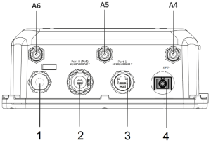
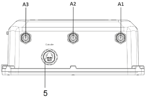
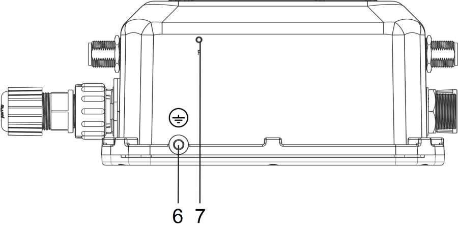
Figure 1 – WOP-12ac side panel layout
Connectors and controls located on the device panels are listed in Table 2.4.
Table 2 – Description of ports and controls
| Panel element | Description | |
|---|---|---|
| A1-A3 | Radio 1 interface connectors for connection of 2.4 GHz external antennas | |
| A4-A6 | Radio 2 interface connectors for connection of 5 GHz external antennas | |
| 1 | Connector for power supply | |
| 2 | Port 0 (PoE) | 10/100/1000 Base-T port (RJ-45 with PoE+ support |
| 3 | Port 1 | 10/100/1000 Base-T port (RJ-45 connector) |
| 4 | SFP | Optical connector SC/UPC (only for WOP-12ac ER SFP) or SC/APC (only for WOP-12ac ER GPON) |
| 5 | Console | Connector for console cable connection (RJ-45 connector) |
| 6 | Ground | |
| 7 | F | Functional button closed by hermetical screw |
The device schematic structure
Figure 2 shows WOP-12ac schematic structure.

Figure 2 – WOP-12ac schematic structure
- A1-A6– connectors for antennas;
- Radio 1– radio interface that performs reception and transmission of data in wireless networks in the range of 2.4 GHz;
- Radio 2– radio interface that performs reception and transmission of data in wireless networks in the range of 5 GHz;
- CPU– controller performing the device control, monitoring and data transmission via wired network;
- Power Supply Unit– power supply unit of the device;
- Port 0 (PoE)– Gigabit Ethernet connector with PoE technology allows you to supply access point and to provide access speed of up to 1Gbps;
- Port 1– Gigabit Ethernet connector provides speed access of up to 1 Gbps;
- Console– RJ-45 connector for console cable connection;
- PowerConnector – connector for power supply connection when PoE is not available.
Reset to the default settings
In order to reset the device to factory settings, press and hold the 'F' button within 15 seconds when the device in loaded state. Device will be rebooted automatically. DHCP client will be launched by default. If the address is not received via DHCP the device will have IP address — 192.168.1.10, subnet mask — 255.255.255.0 and User Name/Password to access via Web interface: admin/password.
Delivery package
The delivery package includes:
- WOP-12ac wireless access point;
- 3 connectors for RJ-45;
- 1 connector for power supply;
- Grounding kit;
- Mounting kit;
- Operating manual (supplied on a CD);
- Conformity certificate;
- Technical passport.
Installation order
This section defines safety rules, installation recommendations, setup procedure and the device starting procedure.
Safety rules
- Do not open the device case. There are no user serviceable parts inside.
- It is required to cover unused antenna connectors by safety cover included in the device delivery package.
- Do not install the device during a thunderstorm. There is a risk of being struck by lightning.
- You must follow requirements for voltage, current and frequency specified in the user manual.
- Measuring devices and computer must be grounded before connecting to the device. Potential difference between cases of equipment and measurement devices must be no more than 1 V.
- Check the cable integrity and security of mounting to the connectors.
- Do not install the device near heat source and at places where temperature may reach values below -40°С or higher 60°С.
- You should satisfy established standards and requirements for working at height during the device installation on the high-rise constructions.
- The device exploitation should be performed by specially prepared engineering and technical personnel.
- Connect only to operational service equipment.
Installation recommendations
- The recommended installation: attaching to a mast/pole or wall;
- Before you install and enable device, check the device for visible mechanical defects. If defects are observed you should stop the device installation and draw up corresponding act.
- During the device installation to provide Wi-Fi coverage area with the best characteristics take into account the following rules:
- Install the device at the center of a wireless network;
- Minimize the number of obstacles (walls, roof, furniture and etc.) between WOP-2ac and other wireless network devices;
- Do not install the device near (about 2 m) electrical and radio devices;
- It is not recommended to use radiophone and other equipment operating on the frequency of 2.4 GHz, 5 GHz in Wi-Fi effective radius;
- Obstacles in the form of glass/metal constructions, brick/concrete walls, water cans and mirrors can significantly reduce Wi-Fi action radius.
- During the installation of several access points, cell action radius must overlap with action radius of a neighboring cell at level of -65 ÷ -70 dBm. Decreasing of the signal level on cells borders to -75 dBm is permitted if it involves the use of VoIP, streaming video and other traffic that is sensitive to losses in wireless network.
Calculating the number of required access points
Table 3 – Attenuation values
Material | Change of signal level, dB | |
|---|---|---|
| 2.4 GHz | 5 GHz | |
| Organic glass | -0,3 | -0,9 |
| Brick | -4,5 | -14,6 |
| Glass | -0,5 | -1,7 |
| Plaster slab | -0,5 | -0,8 |
| Wood laminated plastic | -1,6 | -1,9 |
| Plywood | -1,9 | -1,8 |
| Plaster with wirecloth | -14,8 | -13,2 |
| Breezeblock | -7 | -11 |
| Metal lattice (mesh 13*6 mm, metal 2mm) | -21 | -13 |
Channel selection for neighboring access points
It is recommended to set nonoverlapping channels to avoid interchannel interference among neighboring access points.
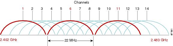
Figure 3 – General diagram of frequency channel closure in the range of 2.4 GHz
For the example of channel allocation scheme among neighboring access points in frequency range of 2.4 GHz when channel width is 20 МHz, see Figure 4.

Figure 4 – Scheme of channel allocation among neighboring access points in the frequency range of 2.4 GHz when channel width is 20 MHz
Similarly, the procedure of channel allocation is recommended to save for access point allocation between floors, see Figure 5.

Figure 5 – Scheme of channel allocation between neighboring access points that are located between floors
When width of used channel is 40 MHz there is no non-overlapping channels in frequency range of 2.4 GHz. In such cases, you should select channels maximally separated from each other.
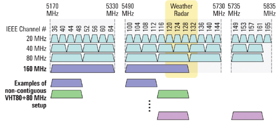
Figure 6 – Channels used in range of 5 GHz when channel width is 20, 40 or 80 MHz
The device installation
The device should be attached to mast/pole or wall in accordance with the safety instruction and recommendations listed above.
The device delivery package includes required mounting kit to attach the device to a mast/pole and wall.
The device installation order:
- Mount brackets to the device;
- Attach the device to a mast/pole or wall;
- Ground the device;
- Connect cables to the device connectors;
- Set up antennas.
Procedure of attaching brackets to the device
Attach brackets (included in the delivery package) to the device before starting the device installation on mast/pole or wall.
Dust-protecting covers must be installed on the antenna connectors included in the device delivery package. You may remove the covers immediately before connecting to the antenna connectors.
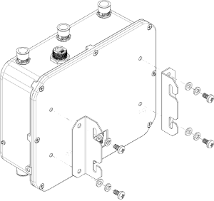
Figure 7 – Mounting brackets to the device
a) Figure 7 shows the required position of brackets.
b) Align four boltholes on brackets with the same boltholes on the device. Attach brackets with screws to the device by using screw-driver.
Algorithm of device mounting to a mast/pole
- Mount the bracket for attaching to a mast/pole:

Figure 8 – Bracket for attaching to mast/pole
a) Connect bracket, that will be attached to a mast/pole, to bracket, that will be attached to the device, as shown in Figure 8.
b) Align two boltholes of both brackets. Attach brackets together by using screwdriver.
2. Attach the bracket to a mast/pole:
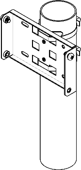
Figure 9 – Mounting bracket on a mast/pole
a) Fix bracket on mast/pole by using clamps, see Figure 9.
b) Install DIN7985 M6 screws in the top holes. Do not screw them fully. Leave at least 3 mm gap, see Figure 9.
3. Attach the device to a mast/pole:

Figure 10 – Mounting the device on a mast/pole
a) Install the device on the top untwisted screws of a bracket attached to a mast/pole, see Figure 10.
b) Install screws to the bottom bolthole, see Figure 10.
c) Tight up the top and bottom screws by using screwdriver.
Order for wall-mounting brackets
- Fix the bracket (included in the delivery package) to the wall:

Figure 11 – Attaching bracket to the wall
Figure 12 – Distance between boltholes
a) Figure 11 shows bracket allocation on the wall. Figure 12 shows distance between the boltholes.
b) Align together four boltholes on bracket and boltholes on the device surface. Screw the brackets to the device surface by using screwdrive.
c) Install DIN7985 M6 screws in the top holes. Do not screw them fully. Leave at least 3 mm gap, see Figure 11.
2. Fix the device on the wall

Figure 13 – Wall-mounting the device
a) Install the device on the top untwisted screws of a bracket attached to the wall, see Figure 13.
b) Install screws in the bottom bolthole, see Figure 13.
c) Tight up the top and bottom screws by using screwdriver.
Grounding scheme of the device
After device installation, you must ground it by using 2.5 mm2 vinyl-insulated wire. Figure 14 shows grounding scheme of the device.


Figure 14 – The device grounding scheme
Application. Power connector pin array
Power connector pin array

Figure 15 – 48 V power supply connector pin array
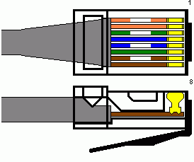
RJ-45 connector pin array
The next scheme is used for twisted-pair wiring.
| Side А:
|
| RJ-45 connector |
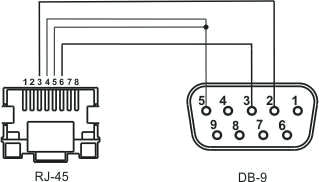
RJ45-DB9 console cable pin array
Table 4 – RJ45-DB9 connector pin array
| Serial Port (RJ-45 Connector) Pin | Adapter (DB-9) Pin |
|---|---|
| 3 (TXD) | 2 (RXD) |
| 4 (Signaling Ground) | 5 (Signaling Ground) |
| 5 (Signaling Ground) | 5 (Signaling Ground) |
| 6 (RXD) | 3 (TXD) |
The example of implementation is shown on the following figure:
List of changes
| Document version | Issue date | Revisions |
|---|---|---|
| Version 1.20 | 09.04.2020 | Synchronization with firmware version 1.19.3 |
| Version 1.19 | 24.02.2020 | Synchronization with firmware version 1.19.0 |
| Version 1.18 | 01.10.2019 | Synchronization with firmware version 1.18.1 |
| Version 1.17 | 05.06.2019 | Synchronization with firmware version 1.17.0 |
| Version 1.16 | 12.02.2019 | Synchronization with firmware version 1.16.0 |
| Version 1.15 | 30.11.2018 | Synchronization with firmware version 1.15.0 |
| Version 1.14 | 10.08.2018 | Synchronization with firmware version 1.14.0 |
| Version 1.13 | 08.05.2018 | Synchronization with firmware version 1.12.2 Changes in section:
|
| Version 1.12 | 26.12.2017 | Synchronization with firmware version 1.11.4 |
| Version 1.11 | 30.10.2017 | Synchronization with firmware version 1.11.2 |
| Version 1.10 | 01.07.2017 | Synchronization with firmware version 1.10.0 |
| Version 1.9 | 06.02.2017 | Synchronization with firmware version 1.9.0 |
| Version 1.8 | 20.09.2016 | Synchronization with firmware version 1.8.0 |
| Version 1.7 | 19.07.2016 | Synchronization with firmware version 1.7.0 Changes in section:
|
| Version 1.6 | 06.07.2016 | Synchronization with firmware version 1.6.5 |
| Version 1.5 | 16.05.2016 | Synchronization with firmware version 1.6.4 |
| Version 1.4 | 30.11.2015 | Changes in section:
|
| Version 1.3 | 13.10.2015 | Synchronization with firmware version 1.6.2 |
| Version 1.2 | 16.04.2015 | Synchronization with firmware version 1.5.0
|
| Version 1.1 | 10.02.2015 | Chapter added: Antenna technical parameters |
| Version 1.0 | 26.09.2014 | First issue |
| Firmware version 1.19.3 | ||