To move to configuration mode, choose one of the following tab "Network", "VoIP" or "System" depending on the configuration goals:
- In the "Network" menu, the network settings of the device are configured;
- In the "VoIP" menu, the following is configured: SIP settings, accounts settings, codecs installation, VAS and dialplan settings;
- In the "System" menu, system time, access to the device via different protocols, change passwords, update firmware are configured.
Configuration mode elements:
"Network" menu
In the "Network" menu, the network settings of the device are configured.
"Internet" submenu
In the "Internet" submenu, you can configure LAN (via PPPoE, DHCP, Static and No IP).
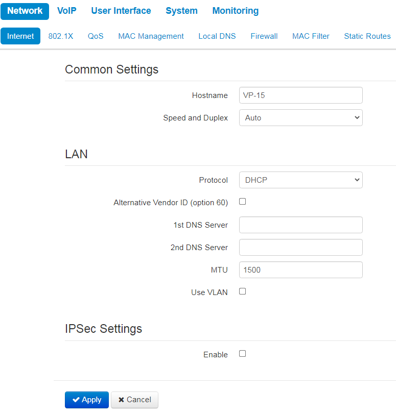
Common settings
- Hostname — device network name.
- Speed and Duplex — specify data rate and duplex mode for LAN Ethernet port of the device:
- Auto — automatic speed and duplex negotiation;
- 100 Half — 100 Mbps data transfer rate with half-duplex mode is supported;
- 100 Full — 100 Mbps data transfer rate with duplex mode is supported;
- 10 Half — 10 Mbps data transfer rate with half-duplex mode is supported;
- 10 Full — 10 Mbps data transfer rate with duplex mode is supported.
LAN
- Protocol — select the protocol that will be used for device LAN interface connection to a data network:
- Static — operation mode where IP address and all the necessary parameters for LAN interface are assigned statically;
- DHCP — operation mode where IP address, subnet mask, DNS address, default gateway and other necessary settings for network operation are automatically obtained from DHCP server;
- PPPoE — operation mode when PPP session is established on LAN interface over Ethernet;
- No IP — operation mode when IP address is not assigned to the interface.
Static protocol
When "Static" type is selected, the following parameters will be available for editing:
- IP Address — specify the device LAN interface IP address in the data network;
- Netmask — external subnet mask;
- Default gateway — address that the packet will be sent to, when route for it is not found in the routing table;
- 1st DNS Server, 2nd DNS Server — domain name server addresses (allow identifying the IP address of the device by its domain name). You can leave these fields empty, if they are not required;
- MTU — maximum size of the data unit transmitted on the network.
DHCP protocol
When "DHCP" type is selected, the following parameters will be available for editing:
- Alternative Vendor ID (Option 60) — when selected, the device transmits Vendor ID (Option 60) field value in Option 60 DHCP messages (Vendor class ID). When not selected, a default value is transmitted in Option 60 in the following format:
- [VENDOR: device vendor][DEVICE: device type][HW: hardware version][SN: serial number][WAN: WAN interface MAC address][LAN: LAN interface MAC address][VERSION: firmware version]
Example: [VENDOR:Eltex][DEVICE:VP-12P][HW:1.0][SN:VI23000118] [WAN:A8:F9:4B:03:2A:D0][LAN:02:20:80:a8:f9:4b][VERSION:#1.1.0].
- [VENDOR: device vendor][DEVICE: device type][HW: hardware version][SN: serial number][WAN: WAN interface MAC address][LAN: LAN interface MAC address][VERSION: firmware version]
- Vendor ID (Option 60) — option 60 value (Vendor class ID) which is transmitted in DHCP messages. When the field is empty, option 60 is not transmitted in DHCP messages;
- 1st DNS Server, 2nd DNS Server — domain name server addresses (allow identifying the IP address of the device by its domain name. Addresses, which are specified statically, have the higher priority than addresses obtained via DHCP;
- MTU — maximum size of the data unit transmitted on the network.
You can manually assign the list of used DHCP options on each network interface. See Appendix DHCP client configuration in multiservice mode.
PPPoE protocol
When "PPPoE" type is selected, the following parameters will be available for editing:
- User Name — username for authorization on PPP server;
- Password — password for authorization;
- MTU — maximum size of the data unit transmitted on the network (recommended value — 1492);
- Service-Name — tag value in PADI message (this field is optional);
- Secondary access — type of access (IPOE) to local area network resources. You can select 2 options:
- DHCP — dynamic access when IP address and other required parameters are obtained via DHCP;
Static — specifying access settings manually: IP address, subnet mask, DNS server, gateway.
When you choose one of the ways of IP addresses assignment, the additional parameters will be displayed according to the selected protocol.
- Use the Secondary Access for VoIP — this option is available, if there are no dedicated interfaces for VoIP service ('Use Internet settings' checkbox is selected). When the checkbox is not selected (default value), VoIP service uses PPP interface for its operation; when selected, the secondary access interface (IPoE);
- Alternative Vendor ID (Option 60) — when selected, the device transmits Vendor ID (Option 60) field value in Option 60 DHCP messages (Vendor class ID). If the field is empty, Option 60 will not be transmitted in DHCP messages:
- [VENDOR :device vendor][ DEVICE :device type][ HW :hardware version] [ SN :serial number][ WAN :WAN interface MAC address][ LAN :LAN interface MAC address][ VERSION :firmware version]
Example: [VENDOR:Eltex][DEVICE:VP-12P][HW:1.0][SN:VI23000118] [WAN:A8:F9:4B:03:2A:D0][LAN:02:20:80:a8:f9:4b][VERSION:#1.1.0].
- [VENDOR :device vendor][ DEVICE :device type][ HW :hardware version] [ SN :serial number][ WAN :WAN interface MAC address][ LAN :LAN interface MAC address][ VERSION :firmware version]
- Vendor ID (Option 60) — option 60 value (Vendor class ID) which is transmitted in DHCP messages. When the field is empty, option 60 is not transmitted in DHCP messages.
No IP protocol
When this mode is selected, IP address will not be assigned to the network interface. This mode is used when IP telephony operates in an allocated VLAN.
Be careful when selecting this mode. Before the mode is selected, make sure that VoIP VLAN has been activated (see "Network settings" submenu (VoIP)) and there is access for management through the corresponding interface (see "Access" submenu).
Use VLAN
VLAN (virtual local area network) is a group of hosts united in a network not depending on the physical location. The devices grouped to a VLAN have the same VLAN identifier (ID).
- Use VLAN — use VLAN identifier specified below to enter the network:
- VLAN ID — VLAN identifier which is used for the device;
- 802.1P — 802.1P attribute (also called CoS — Class of Service) is attached to egress IP frames. The value is from 0 (the least priority) to 7 (the highest priority).
IPsec settings
In this section you can configure IPSec encryption (IP Security).
IPSec is a set of protocols used for protection of data transmitted via Internet Protocol that enables authentication, integrity check and/or encryption of IP packets. IPSec also includes secure Internet Key Exchange protocols.
In the current firmware version you can only access the device management interfaces (web, Telnet) using IPsec.
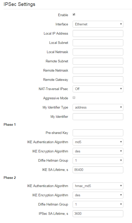
- Enable — enable IPSec protocol utilization for data encryption;
- Interface — this setting takes effect only when PPPoE is selected for the Internet, and defines the interface that will be accessed with IPSec: Ethernet (secondary access interface) or PPP (primary access interface). When DHCP or Static protocol is selected, there is only a single active interface (Ethernet) for the service that can be accessed with IPSec only;
- Local IP Address — device address for IPSec operation;
- Local Subnet together with a Local Netmask define a local subnet for creation of network-to-network or network-to-point topologies;
- Remote Subnet together with a Remote Netmask define a remote subnet address used for IPSec-encrypted communication. If the mask value is 255.255.255.255, communication is performed with a single host. Mask that differs from 255.255.255.255 allows you to define a whole subnet. Thus, device features allow you to establish 4 network topologies that utilize IPSec traffic encryption: Point-to-Point, Network-to-Point, Point-to-Network, Network-to-Network;
- Remote Gateway — gateway used for remote network access;
- NAT-Traversal IPsec — NAT-T mode selection. NAT-T (NAT Traversal) encapsulates IPSec traffic and simultaneously creates UDP packets to be sent correctly by a NAT device. For this purpose, NAT-T adds an additional UDP header before IPSec packet so it would be processed as an ordinary UDP packet and the recipient host would not perform any integrity checks. When the packet arrives to the destination, UDP header is removed and the packet goes further as an encapsulated IPSec packet. With NAT-T technique you can establish communication between IPSec clients in secured networks and public IPSec hosts via firewalls. NAT-T operation modes:
On — NAT-T mode is activated only when NAT is detected on the way to the destination host;
Force — use NAT-T in any case;
Off — disable NAT-T on connection establishment.
The following NAT-T settings are available:
- NAT-T UDP port — UDP port for packets for IPSec message encapsulation. Default value is 4500;
- Interval Between Sending NAT-T Keepalive Packets, s — periodic message transmission interval for UDP connection keepalive on the device performing NAT functions;
- Aggressive Mode — phase 1 operation mode when all the necessary information is exchanged using three unencrypted packets. In the main mode, the exchange process involves six unencrypted packets.
- My Identifier Type — device identifier type: address, fqdn, keyed, user_fqdn, asn1dn;
- My Identifier — device identifier used for identification during phase 1 (fill in, if required). Identifier format depends on the type.
Phase 1
During the first step (phase), two hosts negotiate on the identification method, encryption algorithm, hash algorithm and Diffie Hellman group. Also, they identify each other. For phase 1, there are the following settings:
- Pre-shared Key — a secret key used by authentication algorithm in phase 1. It is represented by a string from 8 to 63 characters;
- IKE Authentication Algorithm — select an authentication algorithm from the list: MD5, SHA1;
- — select an encryption algorithm from the list : DES, 3DES, Blowfish;
- Diffie Hellman Group — select an Diffie-Hellman group;
- — time that should pass for hosts' mutual re-identification and policy comparison. Default value is 24 hours (86400 seconds).
Phase 2
During the second step, key data is generated; hosts negotiate on the utilized policy. This mode — also called as 'quick mode' — differs from the phase 1 in that it can be established after the first step only, when all the phase 2 packets are encrypted.
- — select an authentication algorithm from the list: HMAC-MD5, HMAC-SHA1, DES, 3DES;
- IKE Encryption Algorithm — select an encryption algorithm from the list: DES, 3DES, Blowfish;
- Diffie Hellman Group — select Diffie-Hellman group;
- IPSec SA Lifetime, s — time that should pass for the data encryption key changeover (other name 'IPSec SA lifetime'). Default value is 60 minutes (3600 seconds).
To apply a new configuration and store settings into the non-volatile memory, click 'Apply' button. To discard changes, click 'Cancel' button.
"802.1X" submenu
In "802.1X" submenu, you can configure parameters for authentication in compliance with 802.1X specification.
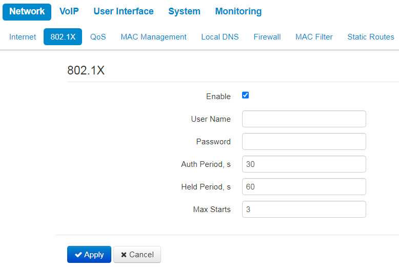
- Enable — set a flag to enable authentication in compliance with 802.1X specification:
- User Name — a user name which is used for authentication;
- Password — a password which is used for authentication;
- Auth Period — a timer used by the Supplicant PAE to determine how long to wait for a response from the Authenticator before timing it out;
- Held Period — a timer used by the Supplicant state machine to define periods of time during which it will not attempt to acquire an Authenticator;
- Max Starts — the maximum number of successive EAPOL-Start messages.
"QoS" submenu
In the "QoS" submenu, you can configure traffic processing priority and queue type.
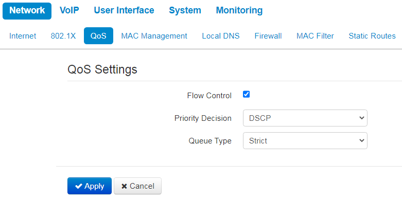
- Flow control — enabling/disabling a mechanism of data flow management by using TCP;
- Priority decision — select traffic prioritization way:
- DSCP — classification mechanism of traffic control and providing quality of service by priorities;
- 802.1p — attribute (CoS — Class of Service) is attached to egress IP packets. The value is from 0 (the least priority) to 7 (the highest priority).
Settings of the priorities are not available when flow control is enabled.
Queue type —select service procedure of queues:
Strict — service procedure of queues when traffic with lowest priority is transmitted only after transmitting queues with higher priority;
WRQ — service procedure of queues, when accessible bandpass is devided among queues in propotion with priority:
- Weight 0..5 — define priority weight in the range from 1 to 127. The higher the weight the more priority the traffic is.
To apply a new configuration and store settings into the non-volatile memory, click 'Apply' button. To discard changes, click 'Cancel' button.
"MAC management" submenu
In the "MAC management" submenu you can change MAC address of the device LAN interface.
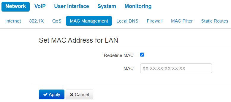
- Redefine МАС — when selected, MAC address from the MAC field is used on the Internet interface;
- MAC — MAC address that will be assigned to the device network interface.
To redefine MAC for 'VoIP' or 'Management VLAN' interface, use sections "Set MAC address for interface 'VoIP'' or "Set MAC address for interface 'Management VLAN''.
To apply a new configuration and store settings into the non-volatile memory, click 'Apply' button. To discard changes, click 'Cancel' button.
"Local DNS" submenu
In "Local DNS" submenu you can configure a local DNS server by adding 'IP address — domain name' pairs into the database.
Local DNS allows the gateway to obtain IP address of the communicating device by its domain name. You can use local DNS in cases when DNS server is missing from the network segment that the gateway belongs to, and you need to establish routing using network names, or when you have to use SIP server network name as its address. Although, you have to know the matches between hostnames (domains) and their IP addresses.
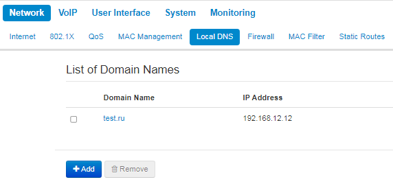
To add the address into the list, click 'Add' button in the "New domain name" window and fill in the following fields:
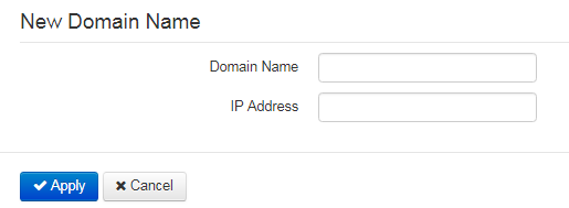
- Domain name — host name;
- IP address — host IP address.
Click 'Apply' to create 'IP address — domain name' pair. To discard changes, click 'Cancel' button. To remove the record from the list, select the checkbox next to the respective record and click 'Delete'.
"Firewall" submenu
In the "Firewall" submenu you can set the rules for the incoming, outgoing and transit traffic transmission. You can restrict transmission of various traffic types (incoming, outgoing, transit) depending on the protocol, source and destination IP addresses, source and destination TCP/UDP ports (for TCP or UDP messages), ICMP message type (for ICMP messages).
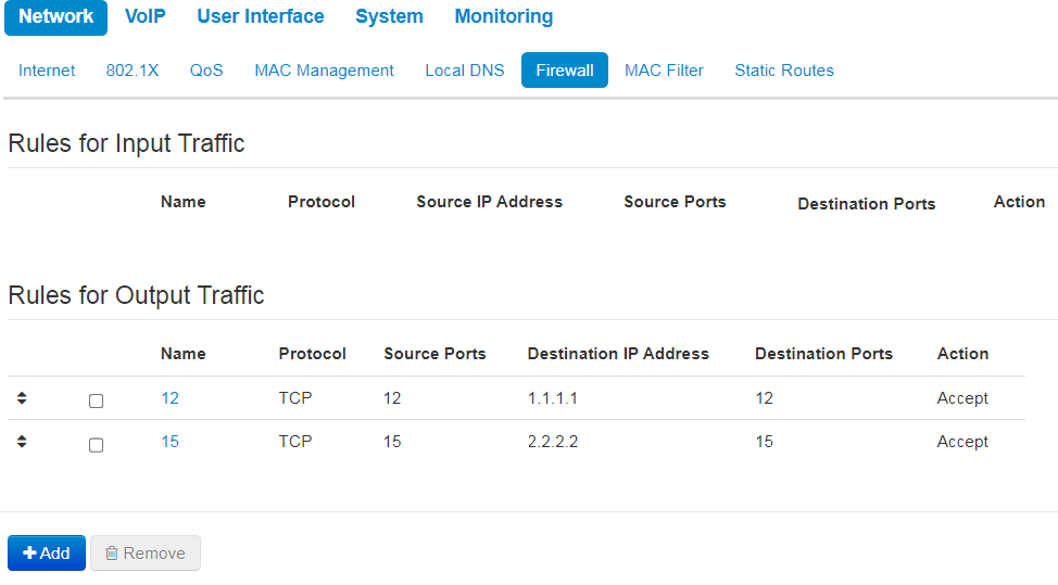
To add a new rule, click 'Add' button and fill in the following fields in the 'Add a New Rule' window:
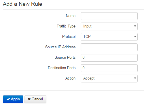
- Name — rule name;
- Traffic Type — select traffic type to which this rule will be applied:
- Input — incoming device traffic (recipient is one of the device network interfaces);
- — define starting source IP address. Use '/' symbol to define a mask in 'xxx.xxx.xxx.xxx' or 'xx' format, e.g. 192.168.16.0/24 or 192.168.16.0/255.255.255.0, when you need to specify an address range (/24 mask record corresponds to /255.255.255.0);
- Output — outgoing device traffic (traffic generated locally by the device from one of the network interfaces):
- Destination IP Address — define destination IP address. Use '/' symbol to define a subnet mask in 'xxx.xxx.xxx.xxx' or 'xx' format, e.g. 192.168.18.0/24 or 192.168.18.0/255.255.255.0, when you need to highlight an address range.
- Input — incoming device traffic (recipient is one of the device network interfaces);
- — packet protocol to which this rule will be applied:
- TCP;
- UDP;
- TCP/UDP;
- ICMP;
- Any.
- Action — an action to be performed on packets (reject/skip).
When TCP, UDP, TCP/UDP are selected, the following settings will become available for editing:
- Source ports — list of source ports with packets falling under the rule (a single port or port range delimited by '-' is permitted);
- Destination ports — list of destination ports. The packets of a destination port fall under this rule (a single port or port range delimited by '-' is permitted).
When ICMP protocol is selected, the following setting will be available for editing:
- Message type — you can create a rule for the specific ICMP message type only for one ICMP message type or for all types.
Click 'Apply' button to add a new rule. To discard changes, click 'Cancel' button. To remove the record from the list, select the checkbox next to the respective record and click 'Delete'.
"MAC filter" submenu
In the "MAC filter" submenu, you can configure access filtering by host's MAC address.
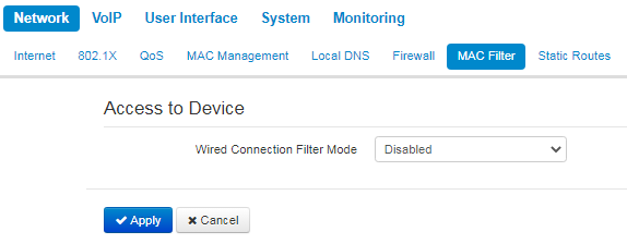
- Wired Connection Filter Mode — define one of the three filter operation modes depending on the host's MAC address:
- Disabled — MAC address filtering is disabled, all clients are allowed to connect to the device;
- Deny — in this filter operation mode, hosts with MAC addresses from the 'MAC address list' are denied to connect to the device. Hosts with unlisted MAC addresses are allowed to connect to the device;
- Allow — in this filter operation mode, hosts with MAC addresses from the 'MAC address list' are allowed to connect to the device. Hosts with unlisted MAC addresses are denied to connect to the device.
MAC address list
You can enter up to 30 host MAC addresses which can access the device in accordance with the specified filtering mode.
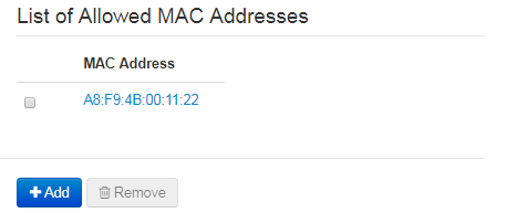
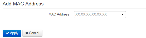
To add a new host to the list, click 'Add' button and enter its MAC address.
To apply a new configuration and store settings into the flash memory, click 'Apply' button. To discard changes, click 'Cancel' button. To delete an entry from the list, set the flag the corresponding entry and click on the 'Delete' button.
"Static Routes" submenu
In the "Static routes" submenu you can configure device static routes.
To add a new route, click 'Add' button and fill in the following fields:
- — route name, used for human perception convenience. You can leave this field empty;
- Destination IP — IP address of destination host or subnet that the route should be established to;
- Netmask — subnet mask. Subnet mask for host should be 255.255.255.255, for subnet — depending on its size;
- Gateway — gateway IP address that allows for the access to the 'Destination IP'.
To apply a new configuration and store settings into the non-volatile memory, click 'Apply' button. To discard changes, click 'Cancel' button.
"VoIP" menu
In the "VoIP" menu you can configure VoIP (Voice over IP): SIP protocol configuration, account configuration, installation of codecs, VAS and dialplan.
"Network settings" submenu (VoIP)
In the "Network Settings" submenu you can specify custom network settings for VoIP service.
- Use Internet Settings — when selected, use network settings specified in the "Network" -> "Internet" menu, otherwise use settings specified in this menu;
VLAN settings
- Use VLAN — when selected, VoIP service will use a dedicated interface in a separate VLAN for its operation, with VLAN number specified in 'VLAN ID' field;
- VLAN ID — VLAN identifier which is used for the network interface;
- 802.1P — attribute (CoS — Class of Service) is attached to egress IP packets. The value is from 0 (the least priority) to 7 (the highest priority).
Network settings
- — select protocol assigning address to VoIP service interface:
- Static — operation mode where IP address and all the necessary settings for LAN interface are assigned manually. When 'Static' type is selected, the following parameters will be available for editing;
- DHCP — operation mode where IP address, subnet mask, DNS address and other necessary settings for service operation (e.g. SIP and registration server static routes) are automatically obtained from DHCP server.
Static protocol
When "Static" type is selected, the following parameters will be available for editing:
- IP Address — specify the device LAN interface IP address in the provider network;
- Netmask — external subnet mask;
- Default gateway — IP address of default gateway;
- 1st DNS Server, 2nd DNS Server — domain name server addresses.
DHCP protocol
When "DHCP" type is selected, the following parameters will be available for editing:
- Alternative Vendor ID (Option 60) — when selected, the device transmits Vendor ID (Option 60) field value in Option 60 DHCP messages (Vendor class ID). If the field is empty, Option 60 will not be transmitted in DHCP messages:
- [VENDOR :device vendor][ DEVICE :device type][ HW :hardware version] [ SN :serial number][ WAN :WAN interface MAC address][ LAN :LAN interface MAC address][ VERSION :firmware version]
Example: [VENDOR:Eltex][DEVICE:VP-12P][HW:1.0][SN:VI23000118] [WAN:A8:F9:4B:03:2A:D0][LAN:02:20:80:a8:f9:4b][VERSION:#1.1.0]
- [VENDOR :device vendor][ DEVICE :device type][ HW :hardware version] [ SN :serial number][ WAN :WAN interface MAC address][ LAN :LAN interface MAC address][ VERSION :firmware version]
- Alternative Vendor ID (Option 60) — when selected, the device transmits Vendor ID (Option 60) field value in Option 60 DHCP messages (Vendor class ID). If the field is empty, Option 60 will not be transmitted in DHCP messages:
- Vendor ID (Option 60) — option 60 value (Vendor class ID) which is transmitted in DHCP messages. When the field is empty, option 60 is not transmitted in DHCP messages.
- 1st DNS Server, 2nd DNS Server — domain name server addresses (allow identifying the IP address of the device by its domain name). Addresses, which are specified statically, have the higher priority than addresses obtained via DHCP.
You can manually assign the list of used DHCP options on each network interface (Internet, VoIP, and Management). See Appendix DHCP client configuration in multiservice mode.
IPsec settings
In this section you can configure IPSec encryption (IP Security). IPSec is a set of protocols used for protection of data transmitted via Internet Protocol that enables authentication, integrity check and/or encryption of IP packets. IPSec also includes secure Internet Key Exchange protocols.
In the current firmware version you can only access the device management interfaces (web and Telnet) using IPSec.
For detailed information on IPSec settings see "Internet" submenu in IPsec settings section.
To apply a new configuration and store settings into the non-volatile memory, click 'Apply' button. To discard changes, click 'Cancel' button.
"SIP Accounts" submenu
Use drop-down 'SIP Accounts' menu to select account for editing.
You can assign own SIP server addresses, registration servers, voice codecs, individualized dialing plan and other parameters for each account.
General settings
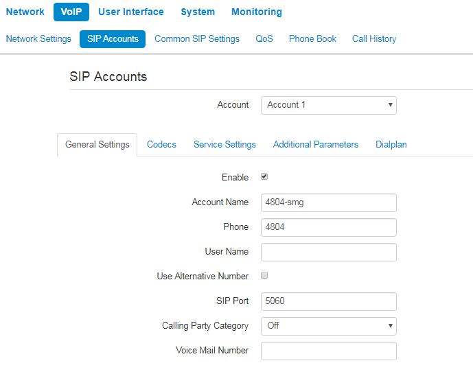
- — when selected, account is active;
- Account Name — an account tag, which will be used for identifying active account or account by default;
- — subscriber number assigned to the account;
- — user name associated with the account (shown in 'Display-Name' field of 'From' header in the outgoing SIP messages);
- Use Alternative Number — when selected, an alternative number will be inserted into the 'From' header of SIP messages sent from this account (particularly, in order to hide the real number from the Caller ID system of the callee):
- Use As a Contact Header — alternative number assigned to a phone port will be changed to specified number and inserted into 'Contact' header of the SIP message.
- — UDP port for incoming SIP message reception for this account, and for outgoing SIP message transmission from this account. It can take values from 1 to 65535 (default value: 5060);
- Calling Party Category — enables transmission of outgoing messages in the 'From' header; the last header is transmitted in Tel-URI format (see RFC3966);
- Voice Mail Number — a number which a call will be established to when subscriber selects "Call" (to listen voice mail messages) in voice mail menu.
Authentication
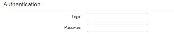
- — user name used for subscriber authentication on SIP server (and on registration server);
- — password used for subscriber authentication on SIP server (and on registration server).
SIP parameters
Use 'SIP Parameters' section to configure SIP parameters of the account.
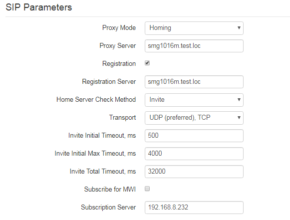
- Proxy Mode — you can select SIP server operation mode in the drop-down list:
- Off;
- Parking — SIP-proxy redundancy mode without main SIP-proxy management;
- Homing — SIP-proxy redundancy mode with main SIP-proxy management.
The phone can operate with a single main SIP-proxy and up to four redundant SIP-proxies. For exclusive operations with the main SIP-proxy, 'Parking' and 'Homing' modes are identical. In this case, if the main SIP-proxy fails, it will take time to restore its operational status.
For operations with redundant SIP-proxies, 'Parking' and 'Homing' modes will work as follows:
The gateway sends INVITE message to the main SIP-proxy address when performing outgoing call, and REGISTER message when performing registration attempt. If on expiration of 'Invite total timeout' there is no response from the main SIP-proxy or response 408 or 503 is received, the phone sends INVITE (or REGISTER) message to the first redundant SIP-proxy address. If it is not available, the request is forwarded to the next redundant SIP-proxy and so forth. When available redundant SIP-proxy is found, registration will be renewed on that SIP-proxy.
Next, the following actions will be available depending on the selected redundancy mode:
In the 'Parking' mode, the main SIP-proxy management is absent, and the phone will continue operation with the redundant SIP-proxy even when the main proxy operation is restored. If the connection to the current SIP-proxy is lost, querying of the subsequent SIP-proxies will be continued using the algorithm described above. If the last redundant SIP-proxy is not available, the querying will continue in a cycle, beginning from the main SIP-proxy.
In the 'Homing' mode, three types of the main SIP-proxy management are available: periodic transmission of OPTIONS messages to its address, periodic transmission of REGISTER messages to its address, or transmission of INVITE request when performing outgoing call. First of all, INVITE request is sent to the main SIP-proxy, and if it is unavailable, then the next redundant one, etc. Regardless of the management type, when the main SIP-proxy operation is restored, the gateway will use it to renew its registration. The gateway will begin operation with the main SIP-proxy.
- — network address of a SIP server — device that manages access to provider's phone network for all subscribers. You can specify IP address as well as the domain name (specify SIP server UDP port after the colon, default value is 5060);
- Registration — when selected, register ports that utilize this profile on registration server;
- — network address of a device that is used for registration of all phone network subscribers in order to provide them with the communication services (specify registration server UDP port after the colon, default value is 5060). You can specify IP address as well as the domain name (you can specify UDP port of a SIP server after the colon, default value is 5060). As a rule, registration server is physically co-located with SIP proxy server (they have the same address);
- — select availability control method for the primary SIP server in 'Homing' mode:
Invite — control via transmission of INVITE request to its address when performing an outgoing call;
Register — control via periodic transmission of REGISTER messages to its address;
Options — control via periodic transmission of OPTIONS messages to its address.
- — periodic message transmission interval in seconds; used for primary SIP server availability check;
— select protocol for SIP messages transport;
Invite Initial Timeout, ms — a time interval between first INVITE transmission and the second one in case there is no answer on the first INVITE (ms). For the following INVITE requests (third, forth, fifth etc.) the interval will be increased twice (i.e. if the value is 300 ms, the second INVITE will be sent in 300 ms, the third — in 600 ms, the forth — in 1200 ms, etc.);
— the maximum time interval for retransmitting non-INVITE requests and responses on INVITE requests;
Invite Total Timeout, ms — common timeout of INVITE requests transmissition (ms). When the timeout is expired, it is defined that the route is not available. INVITE requests retranslation is limited for availability definition as well;
Subscribe for MWI — when checked, the subscription request on "message-summary" events is send. After obtaining such request, subscription server will notify the device on new voice messages through sending NOTIFY requsts;
- Subscriprion Server — a network address, to which SUBSCRIBE requests are sent for subscription on "message-summary" and "dialog" events. You can specify IP address as well as domain name (after colon, you can specify a UDP port of SIP server, default value is 5060).
If you use different values of timeouts on different accounts, be sure that SIP port of the accounts is different as well.
Reserved Proxy
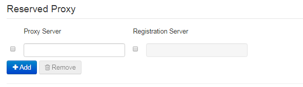
To add redundant SIP proxy, click 'Add' button and enter the following settings:
- Proxy Server — network address of redundant SIP server. You can specify IP address as well as the domain name (specify SIP server UDP port after the colon, default value is 5060);
- Registration Server — network address of redundant registration server (specify UDP port after the colon, default value is 5060). You can specify IP address as well as the domain name. If the 'Registration server' checkbox is selected, the redundant server registration is enabled.
To remove the redundant SIP proxy, select the checkbox next to the specified address and click 'Delete' button.
Additional SIP Properties
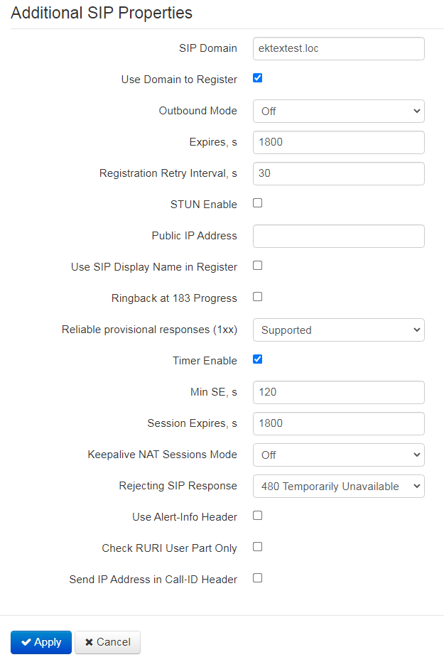
- SIP Domain — domain where the device is located (fill in, if needed);
- Use Domain to Register — when selected, apply SIP domain for registration (SIP domain will be inserted into the 'Request-Line' of 'Register' requests);
- Use Domain to Subscribe — when checked, apply SIP domain for subscription (SIP domain will be inserted into 'Request-Line' of 'SUBSCRIBE' requests);
- Outbound Mode:
- Off — calls will be routed according to the dialplan;
- Outbound — dialplan is required for outgoing communications; however, all calls will be routed via SIP server; if there is no registration, PBX response will be sent to the subscriber in order to enable subscriber service management (VAS management);
- Outbound with «Busy» — dialplan is required for outgoing communications; however, all calls will be routed via SIP server; if there is no registration, VoIP will be unavailable — error tone will be transmitted to the phone headset.
- Expires, s — time for account registration on SIP server. At the average, account registration renewal will be performed after 2/3 of the specified period;
- — when the registration is unsuccessful, time period between SIP server registration attempts;
- Subscription Expires, s — valid time of subscription on events. The subscription renewal is usually performed in 2/3 of the specified period;
- Subscription
- — when checked, STUN (Session Traversal Utilities for NAT) protocol is used for public address of the device definition (external NAT address);
If you use different STUN settings on the different accounts, be sure that SIP ports is different as well.
- Public IP Address — this parameter is used as an external address of the device when it operates behind the NAT (gateway). As a public address, you can specify an external address (WAN) of a gateway (NAT) that VP-12(P) operates through. At that, on the gateway (NAT), you should forward the corresponding SIP and RTP ports used by the device;
- Use SIP Display Name in Register — when selected, use username in 'SIP Display Info' field of the 'Register' message;
- Ringback at 183 Progress — when selected, 'ringback' tone will be sent upon receiving '183 Progress' message (w/o enclosed SDP);
- 100rel — use reliable provisional responses (RFC3262):
- Supported — reliable provisional responses are supported;
- Required — reliable provisional responses are mandatory;
- Off — reliable provisional responses are disabled.
SIP protocol defines two types of responses for connection initiating requests (INVITE)—provisional and final. 2хх, 3хх, 4хх, 5хх and 6хх-class responses are final and their transfer is reliable, with ACK message confirmation. 1хх-class responses, except for '100 Trying' response, are provisional, without confirmation (RFC3261). These responses contain information on the current INVITE request processing step, therefore loss of these responses is unacceptable. Utilization of reliable provisional responses is also stated in SIP (RFC3262) protocol and defined by '100rel' tag presence in the initiating request. In this case, provisional responses are confirmed with PRACK message.
100rel setting operation for outgoing communications:
- Supported — send the following tag in 'INVITE' request — supported: 100rel. In this case, communicating gateway can transfer provisional responses reliably or unreliably — as it deems fit;
- Required — send the following tags in 'INVITE' request — supported: 100rel and required: 100rel. In this case, communicating gateway should perform reliable transfer of provisional replies. If communicating gateway does not support reliable provisional responses, it should reject the request with message 420 and provide the following tag — unsupported: 100rel. In this case, the second INVITE request will be sent without the following tag — required: 100rel;
- Off — do not send any of the following tags in INVITE request — supported: 100rel and required: 100rel. In this case, communicating gateway will perform unreliable transfer of provisional replies.
100rel setting operation for incoming communications :
- Supported, Required — when the following tag is received in 'INVITE' request — supported: 100rel, or required: 100rel — perform reliable transfer of provisional replies. If there is no supported: 100rel tag in INVITE request, the gateway will perform unreliable transfer of provisional replies;
- Off — when the following tag is received in 'INVITE' request — required: 100rel, reject the request with message 420 and provide the following tag — unsupported: 100rel. Otherwise, perform unreliable transfer of provisional replies.
- Timer Enable — when selected, the 'timer' (RFC 4028) extension support is enabled. When connection is established, and both sides support 'timer' extension, one of them periodically sends re-INVITE requests for connection monitoring purposes (if both sides support UPDATE method, wherefore it should be specified in the 'Allow' header, the session update is performed by periodic transmission of UPDATE messages);
- Min SE, s — minimal time interval for connection health checks (90 to 1800s, 120s by default);
- Session Expires, s — period of time in seconds that should pass before the forced session termination if the session is not renewed in time (90 to 80000s, recommended value — 1800s, 0 — unlimited session);
- Keepalive NAT Sessions Mode — select SIP server polling method:
- Off — SIP server will not be polled;
- Options — SIP server polling with OPTIONS message;
- Notify — SIP server polling with NOTIFY message;
- CLRF — SIP server polling with an empty UDP packet.
- Keepalive Timeout, s — SIP server polling time period, in seconds. This parameter is available when "Keppalive NAT Sessions Mode" is set;
- Use Alert-Info Header — process INVITE request 'Alert-Info' header to send a non-standard ringing to the subscriber port;
- Check RURI User Part Only — when selected, only subscriber number (user) will be analyzed, and if the number matches, the call will be assigned to the subscriber port. When unselected, all URI elements (user, host and port — subscriber number, IP address and UDP/TCP port) will be analyzed upon receiving an incoming call. If all URI elements match, the call will be assigned to the subscriber port;
- — when selected, during outgoing communications, device custom IP address will be used in 'Call-ID' header in 'localid@host' format.
To apply a new configuration and store settings into the non-volatile memory, click 'Apply' button. To discard changes, click 'Cancel' button.
Codecs
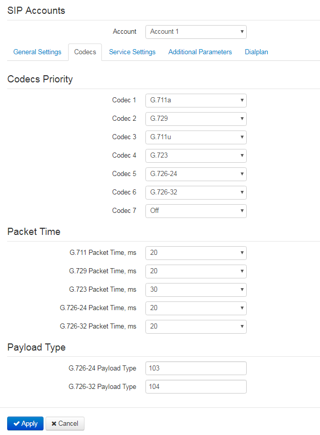
- Codec 1..7 — you can select a codec and an order of their usage. The highest priority codec should be specified in the 'Codec 1' field. For operation, you should specify at least one codec:
- Off — codec will not be used;
- G.711a — use G.711A codec;
- G.711u — use G.711U codec;
- G.723 — use G.723.1 codec;
- G.729 — use G.729 codec;
- G.726-24 — use G.726 codec with the rate of 24 kbps;
- G.726-32 — use G.726 with the rate of 32 kbps.
- Packet Time — amount of voice data in milliseconds (ms) transmitted in a single RTP packet for the corresponding codec G.711А, G.729, G.723 and G.726;
- Payload Type — payload type of G.726-24 or G.726-32 codec (acceptable values are in the range from 96 to 127).
To apply a new configuration and store settings into the non-volatile memory, click 'Apply' button. To discard changes, click 'Cancel' button.
Service settings
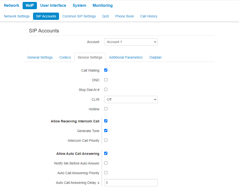
Call Waiting — when checked, the subscriber will accept incoming calls while being in a call state, otherwise '484 Busy here' reply will be sent;
DND — when checked, temporary restriction is placed for incoming calls (DND service — Don’t Disturb);
Stop Dial At # — when checked, use '#' button on the phone unit to end the dialing, otherwise '#' will be recognized as a part of the number;
CLIR — limitation of caller number identification:
Off — CLIR service is disabled;
SIP:From — Anonymous sip:anonymous@unknown.host will be transmitted in the 'From' header of SIP messages;
SIP:From and SIP:Contact — Anonymous sip:anonymous@unknown.host will be transmitted in the 'From' and 'Contact' headers of SIP messages.
Hotline — when checked, 'Hotline' service is enabled. This service enables an outgoing connection automatically without dialling the number after the phone handset is picked up with the defined delay (in seconds). When checked, fill in the following fields:
Hot Number — phone number that will be used for connection establishment upon 'Hot timeout' expiration after the phone handset is picked up (in SIP profile being used, a prefix for this direction should be defined in the dilaplan);
Hot Timeout, s — time interval that will be used for connection establishment with the opposite subscriber, in seconds.
Allow Receiving Intercom Call — when unchecked, incoming intercom calls are declined automatically;
Generate Tone — short sound signal is played before automatic answering to an incoming intercom call;
Intercom Сall Priority — when checked, an incoming intercom call has higher priority than an active call. Before answering to incoming intercom call, an active call is put on hold. When the option is disabled, the function of automatic answering to intercom calls during active call is disabled;
- Allow Auto Call Answering — when the option is enabled all incoming calls will be answered automatically;
- Notify Me Before Auto Answer — short audio signal is played before automatic answering;
- Auto Call Answering Priority — when checked, an incoming call has higher priority than an active call. Before answering to incoming call, an active call is put on hold. When the option is disabled, the function of automatic answering to incoming calls during active call is disabled;
- Auto Call Answering Delay, s — time interval in seconds between the incoming call and the automatic answer to it.
Forwarding parameters
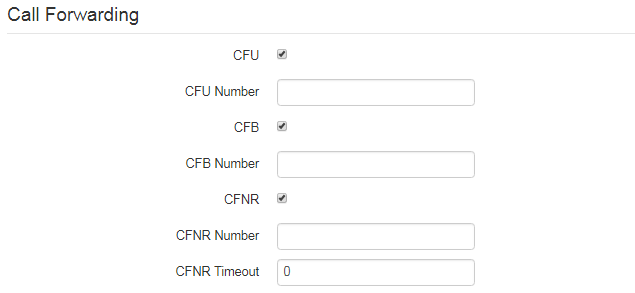
- CFU — when selected, CFU (Call Forwarding Unconditional) service is enabled — all incoming calls will be forwarded to the specified call forwarding unconditional number:
- CFU Number — number that all incoming calls will be forwarded to when Call forwarding unconditional service is enabled (in SIP profile being used, a prefix for this direction should be defined in the dialplan).
- CFB — when selected, CFB (Call Forwarding Busy) service is enabled — forward the call to the specified number, when the subscriber is busy:
- — number that incoming calls will be forwarded to when the subscriber is busy and Call forwarding busy service is enabled (in SIP profile being used, a prefix for this direction should be defined in the dialplan).
- CFNR — when selected, CFNR (Call Forwarding No Reply) service is enabled — forward the call, when there is no answer from the subscriber:
- — number that incoming calls will be forwarded to when there is no answer from the subscriber and 'Call forwarding no reply' service is enabled (in SIP profile being used, a prefix for this direction should be defined in the dialplan);
- — time interval that will be used for call forwarding when there is no answer from the subscriber, in seconds.
When multiple services are enabled simultaneously, the priority will be as follows (in the descending order):
- CFU;
- DND;
- CFB, CFNR.
Three-party conference
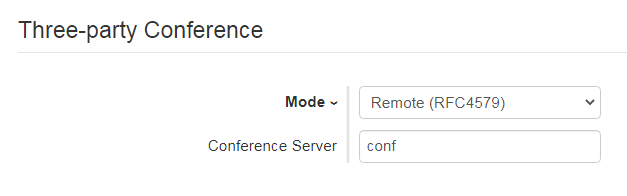
- Mode — operation mode of three-party conference. Two modes are possible:
- Local — conference assembly is performed locally by the device after pressing 'CONF';
- Remote (RFC 4579) — conference assembly is performed at the remote server; after pressing 'CONF', 'Invite' message will be sent to the server using number specified in the 'Conference server' field. In this case, conference operation complies with the algorithm described in RFC 4579.
- — in general, address of the server that establishes conference using algorithm described in RFC 4579. Address is specified in the following format SIP-URI: user@address:port. You can specify the 'user' URI part only — in this case, 'Invite' message will be sent to the SIP proxy address.
Additional Parameters
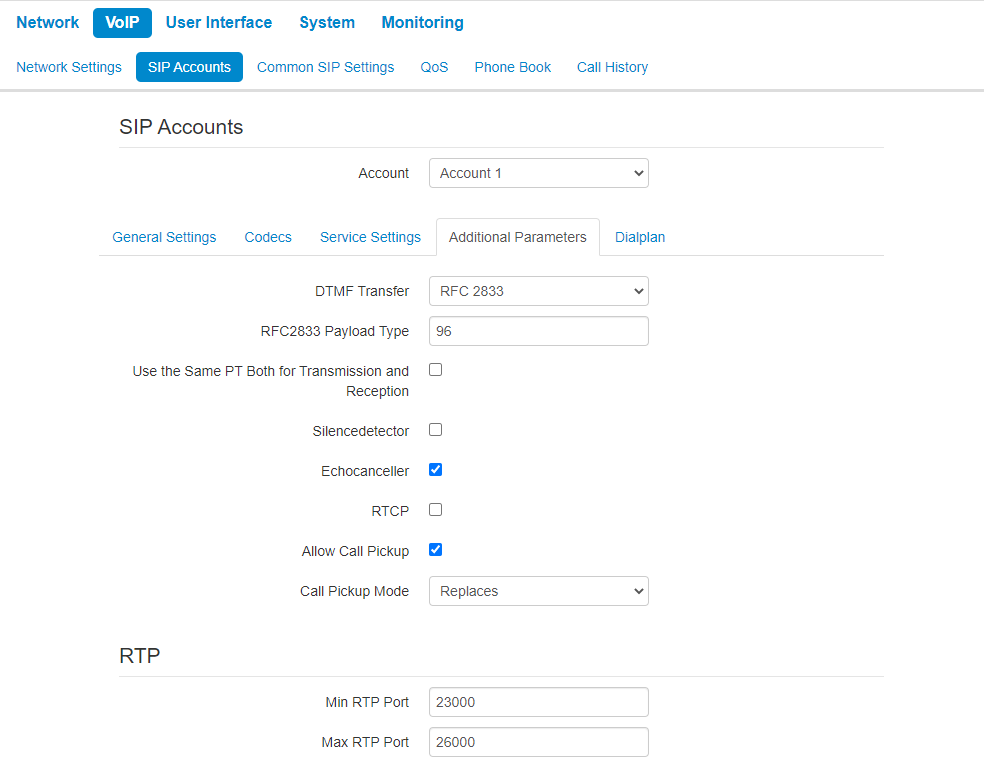
- DTMF Transfer — mode of DTMF signal transmission:
- Inband — inband transmission;
- RFC2833 — according to RFC2833 recommendation as a dedicated payload in RTP voice packets;
- SIP info — transfer messages via SIP in INFO requests.
- SIP info+RFC2833 — transfer messages via SIP in INFO requests according to RFC2833 recommendation as a dedicated payload in RTP voice packets simultaneously;
- RFC2833 Payload Type — payload type for packet transmission via RFC2833 (permitted values: from 96 to 127);
- Use the Same PT Both for Transmission and Reception — option is used in outgoing calls for payload type negotiation of events sent via RFC2833 (DTMF signals). When selected, event transmission and reception via RFC2833 is performed using the payload from 200Ok message sent by the opposite side. When unselected, event transmission is performed via RFC2833 using the payload from 200Ok being received, and reception — using the payload type from its own configuration (specified in the outgoing Invite);
- Silencedetector — when selected, enable voice activity detector;
- — when selected, use echo cancellation;
- RTCP — when selected, use RTCP for voice link monitoring:
- — RTCP packet transmission period, in seconds;
- Receiving Period — RTCP message reception period measured in transmission period units; if there is no single RTCP packet received until the reception period expires, VP-12(P) will terminate the connection;
- RTCP-XR — when selected, RTCP Extended Reports will be sent according to RFC 3611.
- Allow Call Pickup — when the flag is set, pressing the BLF key will initiate the interception of the incoming call to the subscriber on which the BLF key is configured;
- Call Pickup Mode — the way the call is intercepted:
- Replaces — call pickup using the Replaces header;
- Feature Code — call pickup using the prefix added to the number of the subscriber on which the BLF key is configured.
- Call Pickup Code — prefix which will be added to the number of the subscriber to which the BLF key is configured;
- Sign '#' terminates the number — adding the '#' symbol when intercepting a call after the number of the subscriber to which the BLF key is configured.
BLF is configured for keys with built-in LED indicator. The LED indicator shows the status of the caller specified in the advanced settings. Pressing the key initiates a call in standby mode. And in talk mode, it transfers the call to the specified party.
RTP
- — lower limit of the RTP ports range used for voice traffic transmittion;
- — upper limit of the RTP ports range used for voice traffic transmittion.
SRTP
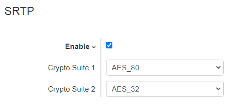
- Enable — when selected, RTP flow encryption is used. Thus, the RTP/SAVP profile will be specified in SDP of outgoing INVITE requests. Also, the SDP of incoming requests will be scanned for the RTP/SAVP profile. If the RTP/SAVP profile is not found, the call will be rejected;
- Crypto Suite 1-2 — allows to choose encryption and hashing algorithms to be used. A suite with the highest priority should be specified in “Crypto Suite 1” field. You have to specify at least one crypto suit:
- AES_80 — according to AES_CM_128_HMAC_SHA1_80;
- AES_32 — according to AES_CM_128_HMAC_SHA1_32.
Jitter Buffer
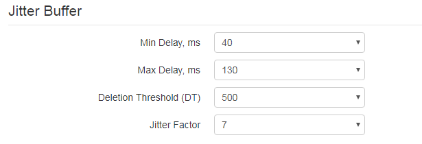
Jitter is a deviation of time periods dedicated to packet delivery. Packet delivery delay and jitter are measured in milliseconds. Jitter value is higher for real time data transfers (e.g. voice or video data).
In RTP, there is a field for precision transmission time tag related to the whole RTP stream. Receiving device uses these time tags to learn when to expect the packet and whether the packet order has been observed. On the basis of this information, the receiving side will learn how to configure its settings in order to evade potential network problems such as delays and jitter. If the expected time for packet delivery from the source to the destination for the whole call period corresponds to the defined value, e.g. 50ms, it is fair to say that there is no jitter in such a network. But packets are delayed in the network frequently, and the delivery time period can fluctuate significantly (in the context of time-critical traffic). If the audio or video recipient application will play packets in the order of their reception time, voice (or video) quality will deteriorate significantly. For example, if the voice data is being transferred, there will be interruptions and interference in the voice.
The device features the following jitter buffer settings:
- Min Delay, ms — minimum expected IP package network propagation delay;
- — maximum expected IP package network propagation delay;
- — maximum time for voice package removal from the buffer. The parameter value should be greater or equal to maximum delay;
- Jitter Factor — parameter used for jitter buffer size optimization. The recommended value is 0.
Input Gain Control
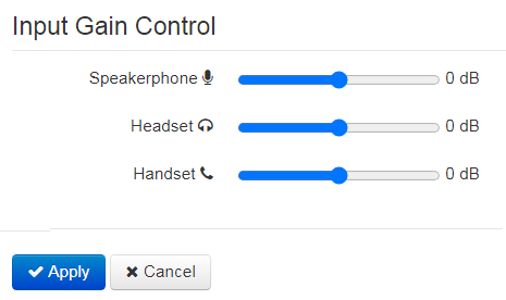
- Speakerphone — specifies the value by which a signal from the speakerphone will be amplified (valid values -9, … 9 dB, at a pitch of 1.5 dB);
- Headset — specifies the value by which a signal from the headset will be amplified (valid values -9, … 9 dB, at a pitch of 1.5 dB);
- Handset — specifies the value by which a signal from the handset will be amplified (valid values -9, … 9 dB, at a pitch of 1.5 dB).
To apply a new configuration and store settings into the non-volatile memory, click 'Apply' button. To discard changes, click 'Cancel' button.
Dialplan
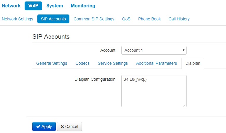
To define a dialplan, use regular expressions in the 'Dialplan configuration' field. The structure and format of regular expressions that enable different dialling features are listed below.
Structure of regular expressions:
S xx , L xx (Rule1 | Rule2 | ... | RuleN)
where:
- хх — arbitrary values of S and L timers;
- () — dialplan margins;
- | — delimiter for dialplan rules;
- Rule1,Rule 2,Rule N — numbers templates which are allowed or forbidden to be called.
Routing rules structure:
Sxx Lxx prefix@optional(parameters)
where:
- хх — arbitrary value of S and L timer. Timers inside rules could be dropped; in this case, global timer values, defined before the parentheses, will be used.
- prefix — prefix part of the rule;
- @optional — optional part of the rule (might be skipped);
- (parameters) — additional options (might be skipped).
Timers
- Interdigit Long Timer («L» character in a dialplan record) — entry timeout for the next digit, if there are no templates that correspond to the dialled combination.
- Interdigit Short Timer («S» character in a dialplan record) — entry timeout for the next digit, if the dialled combination fully matches at least one template and if there is at least one template that requires an extension dialling for the full match.
The timers values might be assigned either for the whole dialplan or for a certain rule. The timers values specified before round brackets are applied for the whole dialplan.
Example: S4 (8XXX.) or S4, L8 (XXX)
If the values of timers are specified in a rule, they are applied to this rule. The value might be located at any position in a template.
Example: (S4 8XXX. | XXX) or ([1-5] XX S0) — an entry requests instant call transmission when 3-digit number dialing; a number should begin with 1,2, … ,5.
Prefix part of the rule
Prefix part might consist of the following elements:
Prefix part elements | Description |
|---|---|
| X or х | Any digit from 0 to 9, equivalent to [0-9] range. |
| 0 - 9 | Digits from 0 to 9. |
| * | Symbol *. |
| # | Symbol #. The use of # in a dialplan can cause blocking of dial completion with the help of # key! |
| [ ] | Specify a range (using dash), enumeration (without gaps, comas and other symbols between digits) or combination of range and enumeration. Example of a range: ([1-5]) — any digit from 1 to 5. Example of enumeration : ([1239]) — any digit out of 1, 2, 3 or 9. Example of a range and enumeration combination: ([1-39]) — the same as in the previous example but in another form. The entry corresponds to any digit from 1 to 3 and 9. |
| {a,b} | Specify the number of reiteration of the symbol placed before round brackets, range or *# symbols. The following entries are possible:
Where:
Example 1: 6{2,5} — 6 might be dialed from 2 to 5 times. The entry equals to the followings 66 | 666 | 6666 |66666 Example 2: 8{2,} — 8 might be dialed 2 and more times. The entry equals to the followings 88 | 888 | 8888 | 88888 | 888888 | ... Example 3: 2{,4} — 2 might be dialed up to 4 times. T he entry equals to the followings 2| 22 | 222 | 2222. |
| . | Special symbol «dot» defines the possibility of reiteration of the previous digit, range or *# symbols for from 0 ad infinitum times. It is equal to {0,} entry. Example : 5х.* — you can not use х in an entry or use it as many times as needed. It is equal to 5* | 5х* | 5xx* |5xxx* |... |
| + | Special symbol «plus» — repeat the previous digit, range or *# symbols from 1ad infinitum times. It is equal to {1,} entry. Example : 7х+ — х is supposed to present in the rule at least 1 time. It is equal to 7х | 7xx |7xxx | 7xxxx |... |
| <arg1:arg2> | Replace dialed sequence. The dialed sequence (arg1) in SIP request to SIP server is changed to another one (arg2). The modification allows deleting — <хх:>, adding — <:хх>, or replacing — <хх:хх> of digits and symbols. Example 1: (<9:8383>XXXXXXX) — the entry corresponds the following dialed digits 9XXXXXXX, but in the transmitted request to SIP server, 9 digit will be replaced to 8383 sequence. Example 2: (<83812:>XXXXXX) — the entry corresponds the following dialed digits 83812XXXXXX, but the sequence 83812 will be omitted and will not be transmitted to a SIP server. |
| , | Paste tone to dialing. When ringing to intercity numbers (or to city number using an office phone) usually, you can hear a dial tone. The dial tone can be realized by putting coma at the needed position in a sequence. Example : (8, 770) — while dialing 8770 sequence you will hear a continuous dial tone (station responce) after dialing 8 digit. |
| ! | Forbid number dialing. If you put ‘!’ symbol at the end of the number template, dialling of numbers corresponding to the template will be blocked. Example : (8 10X xxxxxxx ! | 8 xxx xxxxxxx ) — expression allows long-distance dialling only and denies outgoing international calls. Prohibition rules must be written first. |
Optional part of rules
The optional part of a rule might be omitted. This part might consist the following elements:
Optional part of rules element | Description |
|---|---|
| @host:[port] | Direct address dialing (IP Dialing). «@» placed after the number defines that the dialled call which will be sent to the subsequent server address. Also, IP Dialling address format can be used for numbers intended for the call forwarding. If @host:port is not specified, calls are routed via SIP-proxy. Example: ( 1xxxx@192.168.16.13:5062) — all five-digit dials, beginning with 1, will be routed to 192.168.16.13 IP address to 5062 port. |
Additional parameters
Format: (param1: value1, .., valueN; .. ;paramN: value1, .., valueN)
param — parameter name; several parameters are semicolon-separated and all parameters are enclosed in parentheses;
value — parameter value; several values of one parameter are comma-separated.
Valid parameters and their values:
Parameter | Description |
|---|---|
| line | Account. Placing a call via the accont, possible values 0 and 1. The value 0 corresponds to the first account, the value 1 corresponds to the second account. Example: 12x(line:1) — call to 3-digit numbers beginning with 12 will be performed via the second account. |
Examples
Example 1: ( 8 xxx xxxxxxx ) — 11-digit number beginning with 8.
Example 2: ( 8 xxx xxxxxxx | <:8495> xxxxxxx ) — 11-digit number beginning with 8; if 7-digit number is dialled, add 8495 to the number being sent.
Example 3: (0[123] | 8 [2-9]xx [2-9]xxxxxx) — dialling of emergency call numbers and unusual sets of long-distance numbers.
Example 4: (S0 <:82125551234>) — quickly dial the specified number, similar to 'Hotline' mode.
Example 5: (S5 <:1000> | xxxx) — this dialplan allows you to dial any number that contains digits, and if there was no entry in 5 seconds, dial number '1000' (for example, it belongs to a secretary).
Example 6: (8, 10x.|1xx@10.110.60.51:5060) — this dialplan allows you to dial any number beginning with 810 and containing at least one digit after '810' (after entering '8', 'station reply' tone will be generated) as well as 3-digit numbers beginning with 1. Subscriber calls with 3-digit numbers beginning with 1 will be sent to IP address 10.110.60.51 and port 5060.
Example 7: (S3 *xx#|#xx#|#xx#|*xx*x+#) — managment and usage of VAS.
To apply a new configuration and store settings into the non-volatile memory, click 'Apply' button. To discard changes, click 'Cancel' button.
"Common SIP settings" submenu
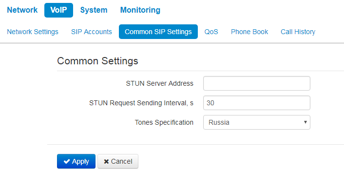
- — STUN server IP address or domain name; you can specify an alternative server port after the colon (default value is 3478);
- STUN Request Sending Interval, s — time period that defines transmission of a request to STUN server. The less the polling period, the faster the response to the public address changes;
- Tones Specification — selecting country to determine tone specification used.
To apply new configuration and save settings into non-volatile memory of the device, click 'Apply' button. To discard changes, click 'Cancel' button.
"QoS" submenu
In the "QoS" submenu you can configure Quality of Service functions.
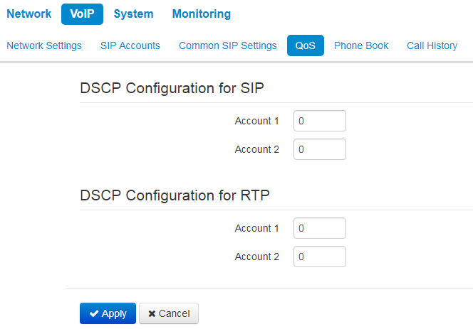
DSCP Configuration for SIP:
- Account 1 — DSCP field value of IP packet header for signalling SIP traffic of the first line.
- Account 2 — DSCP field value of IP packet header for signalling SIP traffic of the second line.
DSCP Configuration for RTP:
- Account 1 — DSCP field value of IP packet header for voice traffic of the first line.
- Account 2 — DSCP field value of IP packet header for voice traffic of the first line.
To apply a new configuration and store settings into the non-volatile memory, click 'Apply' button. To discard changes, click 'Cancel' button.
"Phone Book" submenu
Local phone book management
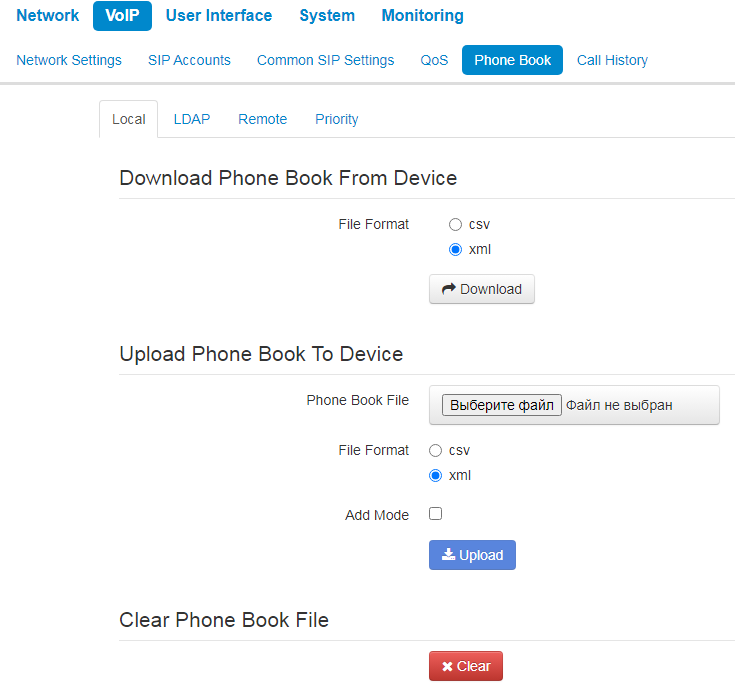
Download Phone Book From Device
Use the section to download a phone book stored on the device.
- File Format — select a format of the file you want to download. The following formats are available:
- csv — text file format where all the conacts are written in the table. The values in the table are separated by the selected separator;
- xml — an eXtensible Markup Language.
- Separator — the symbol for separating data in the table in csv format;
- Add Header — when the option is selected, downloaded csv file will have a header — the first line;
Upload Phone Book To Device
This section is used to configure parameters of restoring a phone bool from the backup copy.
- Phone Book File — select a file:
- File Format — select a format of the file you want to upload. The following formats are available:
- csv — text file format where all the conacts are written in the table. The values in the table are separated by the selected separator;
- xml — an eXtensible Markup Language.
- Exist Header — the option is available only wheb csv format is selected. When checked, it means that the uploaded file has a header — the first line — while import the first line will be ignored;
If 'Add Header' box is not checked, contacts from the loaded file will replace the existing one.
Clear Phone Book File
To clean the phone book, click 'Clear' button.
LDAP. Remote Phone Book management
In the "Phone book" submenu, you can set up the connection to LDAP server and search parameters.
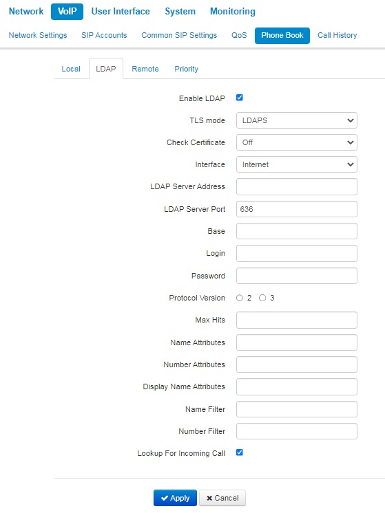
- Enable LDAP — when selected, the phone book is accessible via display menu;
- TLS mode — TLS usage mode. The following modes are available:
- Off — do not use TLS;
- StartTLS — after establishing an unencrypted LDAP connection, the client issues a STARTTLS command to upgrade the connection to an encrypted. After that, the communication between both endpoints is encrypted;
- LDAPS — TLS is used since the start of the LDAP connection.
- Check Certificate — server certificate check mode;
- Interface — selecting the network interface used to send requests to the LDAP server;
- LDAP Server Address — domain name or IP address of LDAP server;
- — port of LDAP server transport protocol;
- — indicates the location of base directory, that contains the phone book, and from which the search begins, in the LDAP directory;
- Login — username that will be used when authorizing on LDAP server;
- Password — password that will be used when authorizing on LDAP server;
- — LDAP protocol version of formed requests;
— the parameter indicating the maximum amount of search results that will be returned by LDAP server;
Too big ‘Max Hits’ value reduces the LDAP search rate, that is why the parameter is to be configured according to the available bandwidth.
Name Attributes — the parameter that indicates the name attribute of each record returned by the LDAP server;
- — the parameter that indicates the number attribute of each record returned by the LDAP server;
- Display Name Attributes — the parameter that indicates the display name attribute of each record returned by the LDAP server;
- — the filter used to lookup for the names. The “*” character in the filter indicates any character. The "%" character in the filter indicates the input string used as the filter condition prefix;
- — the filter used to lookup for the number. The “*” character in the filter indicates any character. The "%" character in the filter indicates the input string used as the filter condition prefix;
— lookup for a name using a number during incoming calls.
To apply a new configuration and store settings into the non-volatile memory, click 'Apply' button. To discard changes, click 'Cancel' button.
Remote Phone Book management
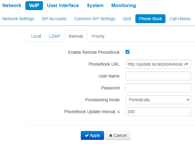
- Enable Remote PhoneBook — when checked, remote phonebook is loaded automatically;
- PhoneBook URL — a full path to the remote phonebook — is set in URL format (the following protocols are available to be used for phonebook loading through: TFTP, FTP, HTTP and HTTPS);
- PhoneBook Update Interval, s — time interval between phonebook updates. If the parameter is set to 0, the phonebook is updated once — right after device loading;
To apply a new configuration and store settings into the non-volatile memory, click 'Apply' button. To discard changes, click 'Cancel' button.
Priority Phone Book management
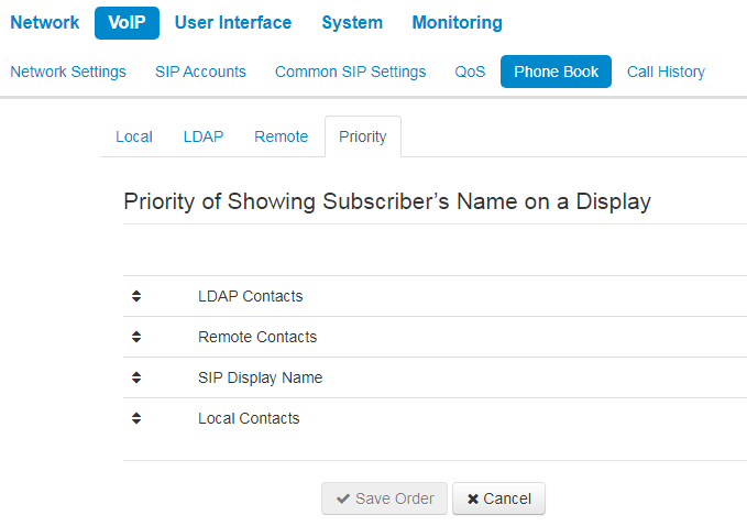
- LDAP Contracts — displaying of names from LDAP pnonebook;
- Remote Contacts — displaying of names from remote pnonebook;
The caller's name will be displayed according to the selected priority. For example, in this case, if the local phone book has the name of the caller, the display will show the name from the local phone book, if not — the name designated in the SIP protocol. If the name is not designated in the SIP protocol, it will be displayed from the remote telephone book, etc.
"Call History" submenu
In the "Call History" submenu you can configure call history logging.
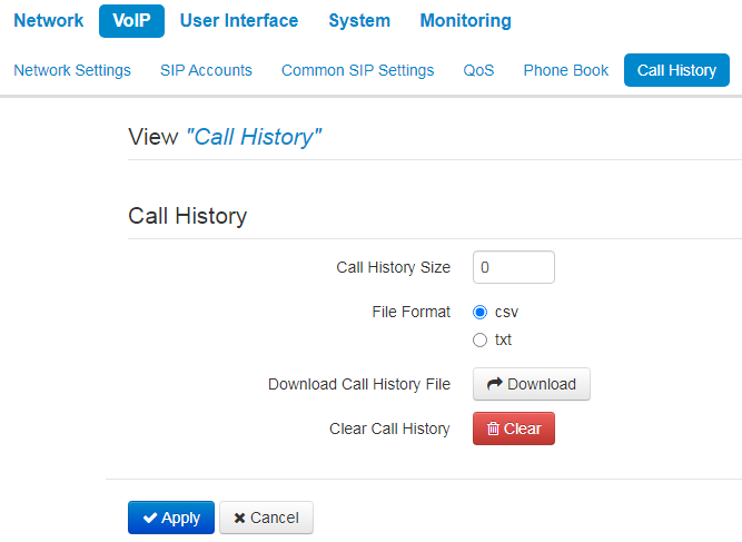
- Call History Size — maximum number of log records, can take values from 0 to 10,000 strings. Enter '0' value to disable call history logging. When the defined log limit is reached, each consequent record will delete the oldest record in the beginning of the log;
- — to save 'voip_history' file on a local PC, click 'Download' button;
- Clear Call History — to clear call history, click 'Clear' button.
To view the call history, follow the "View 'Call History" link. For parameter monitoring description, see section View call history.
To apply a new configuration and store settings into the non-volatile memory, click 'Apply' button. To discard changes, click 'Cancel' button.
"User Interface" menu
"Buttons" submenu
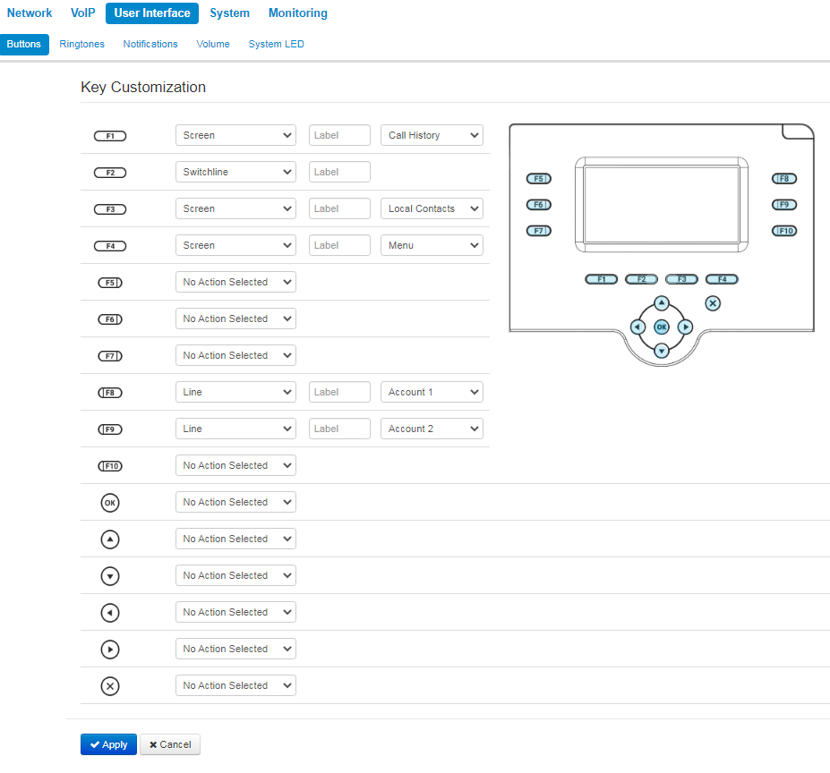
You can choose actions for each button to be performed on pressing. The settings are presented as a table with the following columns:
- Button.
- Action — select action to be performed on the button pressing. The followings are available:
- No action selected — pressing on this button will not be processed;
- Screen — open a screen selected in the additional parameters;
- Call — call the number selected in the additional parameters;
- Switchline — change the account by default;
- BLF — only for buttons with LED indicator. LED indicates line status of the subscriber selected in the additional settings. Pressing the button in stand-by mode initiates a call. In conversation mode, pressing the button redirects the call to the selected subscriber.
- Label — button's label, which is displayed on the screen next to the button.
- Additional settings — select additional parameters for the button (options depend on the action selected).
To BLF function activation, you should specify subscribtion server in SIP account settings.
The "Buttons" tab is available only for VP-15 and VP-15P.
To apply a new configuration and store settings into the non-volatile memory, click 'Apply' button. To discard changes, click 'Cancel' button.
"Ringtones" submenu
In "Ringtones" submenu, you can upload audio files and set them as ringtone. You can assign different ringtones for different accounts.
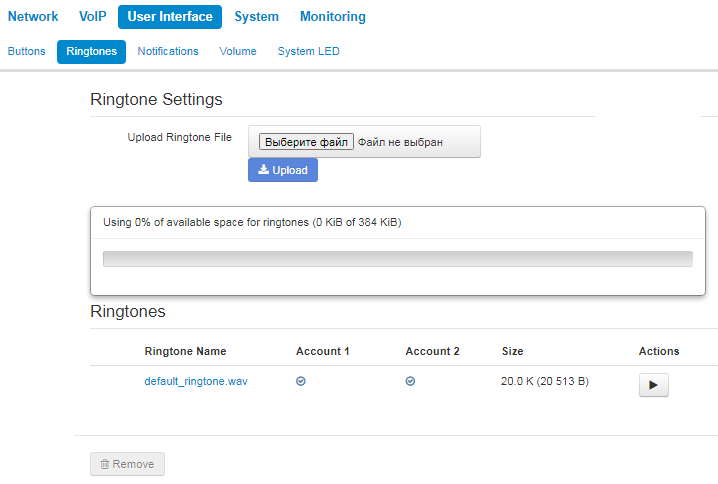
This tab consists of 3 parts:
- a block for audio file uploading;
- drive free space indicator and total drive memory size for audio files storaging;
- list of uploaded audio files.
Before being upload to the storage, audio files are compressed. The indicator shows the size of compressed files.
The list of uploaded audio files is shown in a table with the following columns:
- Ringtone Name — name of the audio file;
- Account 1 — assignment of the ringtone to the Account 1;
- Account 2 — assignment of the ringtone to the Account 2;
- Size — the size of the file before being compressing;
- Actions — a button to play/pause audio file on the device. When the key is pressed, the audio file will be played.
Check and uncheck audio files in the list to select the necessary files and click 'Remove' button below the table to delete them from the storage.
An audio file should satisfy the following requirements to be played correctly:
- Sampling frequency — 8000 Hz;
- Number of channels — 1 (Mono);
- Code size — 8 bit;
- Codec — A-Law.
The example of preparing an audio file is presented in the application Prepairing an audio file to be uploaded as a ringtone.
"Notifications" submenu
In the "Notifications" submenu you can manage the notifications that are displayed on the device screen.
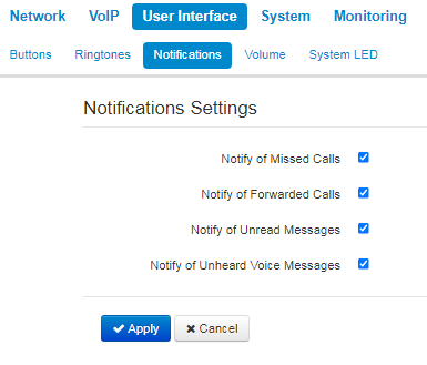
- Notify of Missed Calls — when checked, the display shows notifications of missed calls;
- Notify of Forwarded Calls — when checked, the display shows notifications of forwarded calls;
- Notify of Unread Messages — when checked, the display shows notifications of unread text messages;
- Notify of Unheard Voice Messages — when checked, the display shows notifications of unheard voice messages.
"Volume" submenu
In the "Volume" submenu you can configure the volume in various device operation modes.
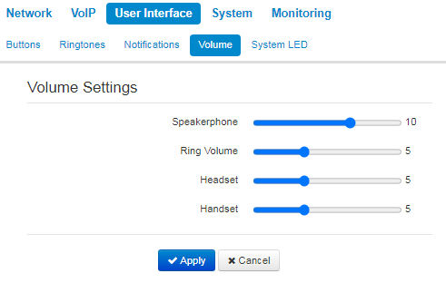
- Speakerphone — speakerphone volume;
- Ring volume — ring volume;
- Headset — headset volume;
- Handset — handset volume.
"System LED" submenu
The system indicator is the LED located on the case in the upper right corner.
In the "System LED" submenu you can configure the operation of the system indicator and the priority for possible events. The indicator first displays the signal of the event that is placed higher in the priority table than the others. In the screenshot below, the highest priority event is "Incoming call", the lowest priority event is "Device on".
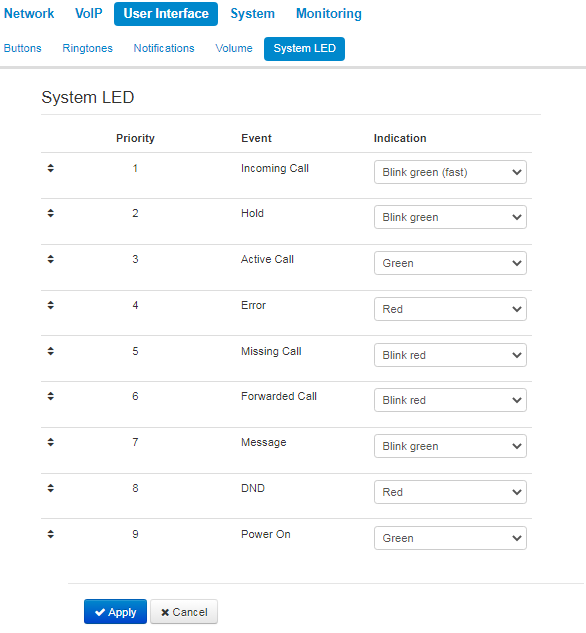
- Disabled;
- Green;
- Red;
- Blink green;
- Blink red;
- Blink green (fast);
- Blink red (fast);
- Alternately green, red;
- Alternately green, red (fast).
"System" menu
In the "System" menu you can configure settings for system, time and access to the device via various protocols, change the device password and update the device firmware.
"Time" submenu
In the "Time" submenu you can configure time synchronization protocol (NTP).
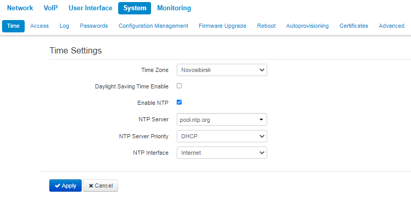
- Time Zone — allows you to set a timezone from the list according to the nearest city in your region;
- Daylight Saving Time Enable — when selected, automatic daylight saving change will be performed automatically within the defined time period:
- — daylight saving change starting day;
- — daylight saving change ending day.
- DST Offset (minutes) — time shift in minutes;
- Enable NTP — select this checkbox to enable device system time synchronization with the particular NTP server;
- NTP Server — time synchronization server IP address/domain name;
- NTP Interface — select network interface used for sending requests of NTP synchronization.
To apply a new configuration and store settings into the non-volatile memory, click 'Apply' button. To discard changes, click 'Cancel' button.
"Access" submenu
In the "Access" submenu you can configure the device access via web interface, Telnet and SSH protocols.
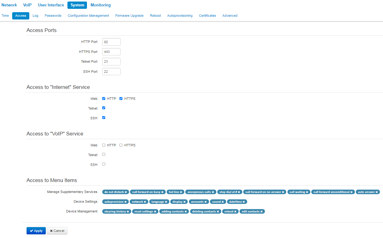
Access ports
In this section you can configure TCP ports for the device access via HTTP, HTTPS, Telnet , and SSH.
- HTTP port — number of the port that allows for the device web interface access via HTTP, default value is 80;
- HTTPS ports — number of the port that allows for the device web interface access via HTTPS (HTTP secure connection), default value is 443;
- Telnet port — number of the port that allows for the device access via Telnet, default value is 23;
- SSH port — number of the port that allows for the device access via SSH, default value is 22.
You can use Telnet and SSH protocols in order to access the command line (Linux console). Username/password for console connection: admin/password.
Access to the Internet service
To get device access from the Internet service interfaces, set the following permissions:
Web
HTTP — when selected, connection to the device web configurator is enabled via HTTP (insecure connection);
HTTPS — when selected, connection to the device web configurator is enabled via HTTPS (secure connection).
Telnet — a protocol that allows you to establish mechanisms of control over the network. Allows you to remotely connect to the gateway from a computer for configuration and management purposes. To enable the device access via Telmet protocol , select the appropriate checkboxes.
SSH — a secure device remote control protocol. However, as opposed to Telnet, SSH encrypts all traffic, including passwords being transferred. To enable the device access via SSH protocol , select the appropriate checkboxes.
Access to VoIP Service
In this section you can configure access to VoIP service interface (to configure VoIP service interface, use VoIP—Network configuration) through the web (HTTP or HTTPS), and also via Telnet and SSH protocols. To enable access to any protocols listed above, select the appropriate checkboxes.
Access to the menu elements
This block includes 3 groups of items, access to which can be denied for a user. If one or another item is specified in the list, then access to it is allowed.
You can deny access by clicking ![]() to the right of menu item name. To allow access to a previously denied menu item, you should click on the
to the right of menu item name. To allow access to a previously denied menu item, you should click on the ![]() button and select the required item from the drop-down list.
button and select the required item from the drop-down list.
To provide the administrator with access to all menu items, including hidden from the user, you should switch to the admin mode.
For access to hidden menu items the same password is used as for the access to web interface.
To apply a new configuration and store settings into the non-volatile memory, click 'Apply' button. To discard changes, click 'Cancel' button.
"Log" submenu
In the "Log" submenu you can configure output for various debug messages intended for device troubleshooting. Debug information is provided by the following device firmware modules:
VoIP Log — deals with VoIP functions operations;
Networkd Log — deals with the device configuration according to the configuration file;
Configd Log — deals with the configuration file operations (config file reads and writes from various sources) and the device monitoring data collection;
Interface Manager Log — deals with the device’s user interface operation (such as keyboard, display, speaker phone, handset and etc.).
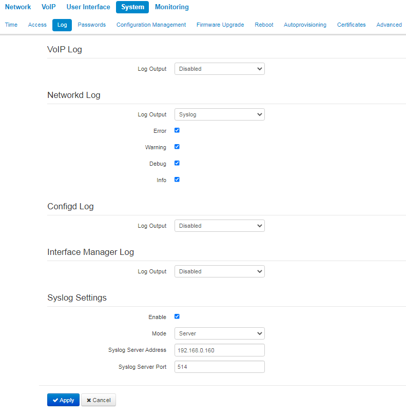
VoIP log
- Log output — log message output direction:
- Disabled — log is disabled;
- Syslog — messages are output to remote server or local file via syslog protocol (for protocol configuration, see below);
- Console — messages are output to the device console (requires connection via COM port adapter);
- Telnet — messages are output to the telnet session; create telnet protocol connection first.
- Error — select this checkbox, if you want to collect «Error» type messages;
- Warnings — select this checkbox, if you want to collect «Warning» type;
- Debug — select this checkbox, if you want to collect debug messages;
- Info — select this checkbox, if you want to collect information messages;
- SIP trace level — defines output level of VoIP SIP manager stack messages.
Network log, configure log, interface manager log
- Log output — log massage output direction:
- Disabled — log is disabled;
Syslog — messages are output to remote server or local file via syslog protocol (for protocol configuration, see below);
Console — messages are output to the device console (requires connection via COM port adapter);
Telnet — messages are output to the telnet session; create telnet protocol connection first.
- Error — select this checkbox, if you want to collect «Error» type messages;
- Warning — select this checkbox, if you want to collect «Warning» type messages;
- Debug — select this checkbox, if you want to collect debug messages;
- Info — select this checkbox, if you want to collect information messages.
Syslog Settings
If there is at least a single log (VoIP manager, system manager or configuration manager) is configured for Syslog output, you should enable Syslog agent that will intercept debug messages from the respective manager and send them to remote server or save them to a local file in Syslog format.
- Enable — when selected, user Syslog agent is launched;
- Mode — Syslog agent operation mode:
- Server — log information will be sent to the remote Syslog server (this is the 'remote log' mode);
- Local file — log information will be saved to the local file;
Server and file — log information will be sent to the remote Syslog server and saved to the local file.
Syslog server address — Syslog server IP address or domain name (required for 'Server' mode);
Syslog server port — port for Syslog server incoming messages (default value is 514; required for 'Server' mode);
- File name — name of the file to store log in Syslog format (required for 'File' mode);
- File size, KB — maximum log file size (required for 'File' mode).
To apply a new configuration and store settings into the non-volatile memory, click 'Apply' button. To discard changes, click 'Cancel' button.
"Password" submenu
In the "Passwords" submenu you can define passwords for administrator, non-privileged user and viewer access.
Defined passwords allow the device access via web interface and also via Telnet protocol.
When signing into web interface, administrator (default password: password) has the full access to the device: read/write any settings, full device status monitoring.
Administator login — admin.
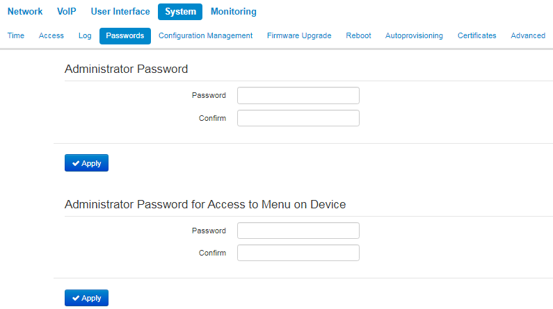
Administrator password — enter administrator password in the respective fields and confirm it.
To apply a new configuration and store settings into the non-volatile memory, click 'Apply' button. To discard changes, click 'Cancel' button.
"Configuration Management" submenu
In the "Configuration management" submenu you can save and update the current configuration.
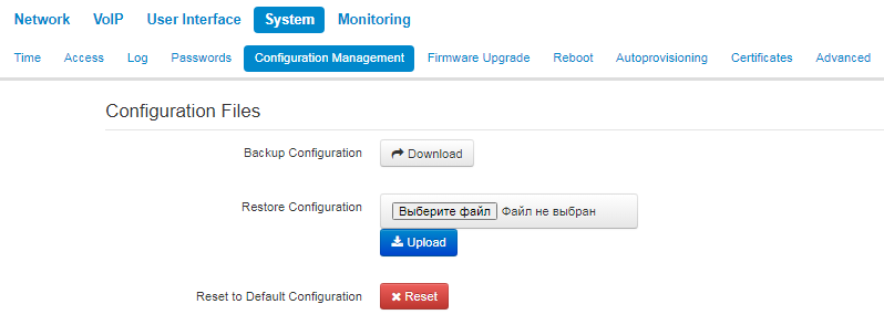
Backup Configuration
To save the current device configuration to a local PC, click 'Download' button.
Restore Configuration
Select configuration file stored on a local PC. To update the device configuration, click 'Select file' button, specify a file (in .tar.gz format) and click 'Upload' button. Uploaded configuration will be applied automatically and does not require device reboot.
Reset to Default Configuration
To reset the device to default settings, click 'Reset' button.
When you reset the device configuration, the followings will be also reset:
- contacts;
- call history;
- text messages.
"Firmware Upgrade" submenu
In "Firmware upgrade" submenu you can update the firmware of the device.
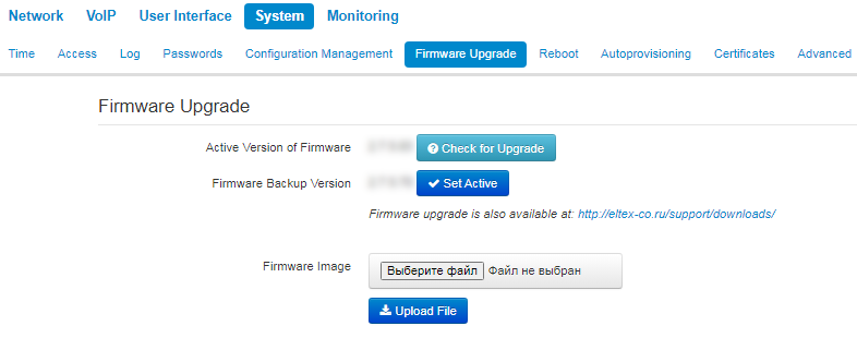
Active Version of Firmware — installed firmware version;
Check for Upgrade — click this button to check the availability of the latest firmware version. With this function, you can quickly check the latest firmware version and update the firmware, if necessary;
Firmware backup version — installed firmware version which can be used in case of problems with the current active firmware virsion;
Set Activate — button allowing you to make a backup of the active firmware version. In order to get that done reboot the device.
Firmware upgrade check function requires Internet access.
You can upgrade the device firmware manually by downloading the firmware file from the web site http://eltex-co.ru/support/downloads/ and saving it on the computer. To do this, click the 'Select file' button in the 'Firmware upgrade file' field, and specify path to firmware .tar.gz format file.
To launch the update process, click 'Upload file' button. The process can take several minutes (its current status will be shown on the page). The device will be automatically rebooted when the update is completed
Do not switch off or reboot the device during the software upgrade.
"Reboot" submenu
In the "Reboot" submenu you can reboot the device.
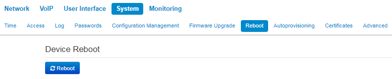
Click the 'Reboot' button to reboot the device. Device reboot process takes approximately 1 minute to complete.
"Autoprovisioning" submenu
In the "Autoprovisioning" submenu you can configure DHCP-based autoprovisioning algorithm and TR-069 subscriber device automatic configuration protocol.
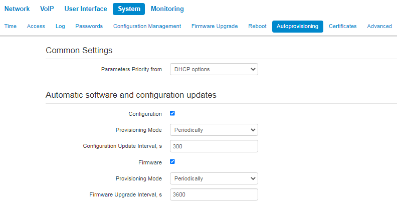
- Parameter priority from — this parameter manages names and locations of configuration and firmware files:
- Static settings — paths to configuration and firmware files are defined by the 'Configuration file' and 'Firmware file' settings correspondingly;
- DHCP options — paths to configuration and firmware files are defined by the DHCP Option 43, 66, and 67 (to do this, you should select DHCP for the Internet service).
For detailed algorithm operation, see "Internet" submenu.
DHCP-based autoprovisioning
- FTP User Name — a user name used for authorization on FTP server when loading configuration or firmware;
- FTP Password — a password used for authorization on FTP server when loading configuration or firmware.
Configuration
Provisioning Mode — to update configuration, you can separately specify one of the several update modes:
Disabled — autoupdate of the device configuration is disabled;
Periodically — the device configuration will be automatically updated after defined period of time;
Scheduled —the device configuration will be automatically updated at specific times and on specific days.
- Configuration File — full path to configuration file—defined in URL format (at this time you can upload configuration files via TFTP and HTTP:
- tftp://<server address>/<full path to cfg file>
- http://<server address>/<full path to cfg file>
- ftp://<server address>/<full path to cfg file>
where <server address> — HTTP, TFTP or FTP server address (domain name or IPv4), < full path to cfg file > — full path to configuration file on server;
- — time period in seconds that will be used for periodic device configuration update; if 0 is selected, device will be updated only once — immediately after startup;
- Time of Configuration Update — time on 24-hour format that will be used for configuration autoupdate;
- Days of Configuration Update — week days with defined time that will be used for configuration autoupdate.
Firmware
- — to update firmware, you can separately specify one of the several update modes:
Disabled — autoupdate of the device configuration or firmware is disabled;
Periodically — the device configuration or firmware will be automatically updated after defined period of time;
Scheduled — the device configuration or firmware will be automatically updated at specific times and on specific days.
- — full path to firmware file — defined in URL format (at this time you can upload firmware files via TFTP and HTTP):
- tftp://<server address>/<full path to firmware file>
- http://<server address>/<full path to firmware file>
- ftp://<server address>/<full path to firmware file>
where <server address> — HTTP, TFTP or FTP server address (domain name or IPv4), < full path to firmware file > — full path to firmware file on server;
- Firmware Upgrade Interval, s — time period in seconds that will be used for periodic device firmware update; if 0 is selected, device will be updated only once — immediately after startup;
- Time of Firmware Upgrade — time on 24-hour format that will be used for firmware autoupdate;
- Days of Firmware Upgrade — week days with defined time that will be used for firmware autoupdate.
For detailed DHCP-based automatic update algorithm, see Appendix Device automatic update algorithm based on DHCP.
TR-069 protocol autoconfiguration
Via TR-069, you can perform full device configuration, firmware update, view device information (firmware version, model, serial number, etc.), upload and download the configuration file and reboot the device remotely.
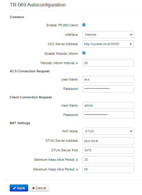
Common
- — when selected, integrated TR-069 protocol client will be enabled;
- — select the interface for TR-069 protocol operation;
- — autoconfiguration server address. Enter address in the following format: http://<address>:<port> or https://<address>:<port> (<address> — ACS server IP address or domain name, <port> — ACS server port, default value is 80). Alternatively, the client will exchange the data with ACS server via the secure protocol — HTTPS. By default, ACS server produced by Eltex utilizes port 9595 for communication;
- — when selected, integrated TR-069 client performs periodic ACS server polling at intervals equal to «Periodic Inform Interval» value, in seconds. Goal of the polling is to identify possible changes in the device configuration.
ACS connection request
- User Name, Password — username and password used by client to ACS.
Client Connection Request
- User Name, Password — username and password used by TR-069 client to access ACS.
NAT Settings
If there is a NAT (network address translation) between the client and ACS, ACS can not be able to establish the connection to client without specific technologies intended to prevent such situations. These technologies allow the client to identify its so called public address (NAT address or in other words external address of a gateway that covers the client). When public address is identified, the client reports it to the server that uses this public address for establishing connection to the client in the future..
- NAT Mode — identifies the method, that will be used by a client for obtaining its public address information. The following modes are possible:
- STUN — use STUN protocol for public NAT address discovery;
- Manual — manual mode, when public address is explicit in configuration; in this mode, you should add a forwarding rule on a device that acts as a NAT for TCP port used by TR-069 client;
- Off — NAT is not used — this mode is recommended only when the device is directly connected to ACS without network address translation. In this case public address will match local client address.
When choosing STUN mode, you should define the following settings:
- — IP address or domain name of STUN server;
- — UDP port of STUN server (3478, by default);
- Minimum Keep Alive Period and Maximum Keep Alive Period — define the time interval in seconds for periodic transmission of messages to STUN server in order to identify public address modification.
For correct ACS operation behind NAT, STUN server minimum polling period should be less than maximum session time provided by NAT device.
To apply a new configuration and store settings into the flash memory, click 'Apply' button. To discard changes, click 'Cancel' button.
"Certificates" submenu
"Certificates" submenu allows to view, download and upload certificates for using in protected TLS connections.
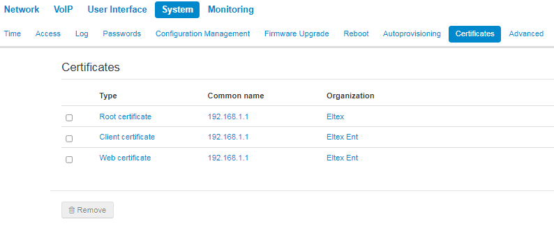
Root certificate
A root certificate is used to authenticate certificates with incoming connections. This certificate must be signed by the certification authority.
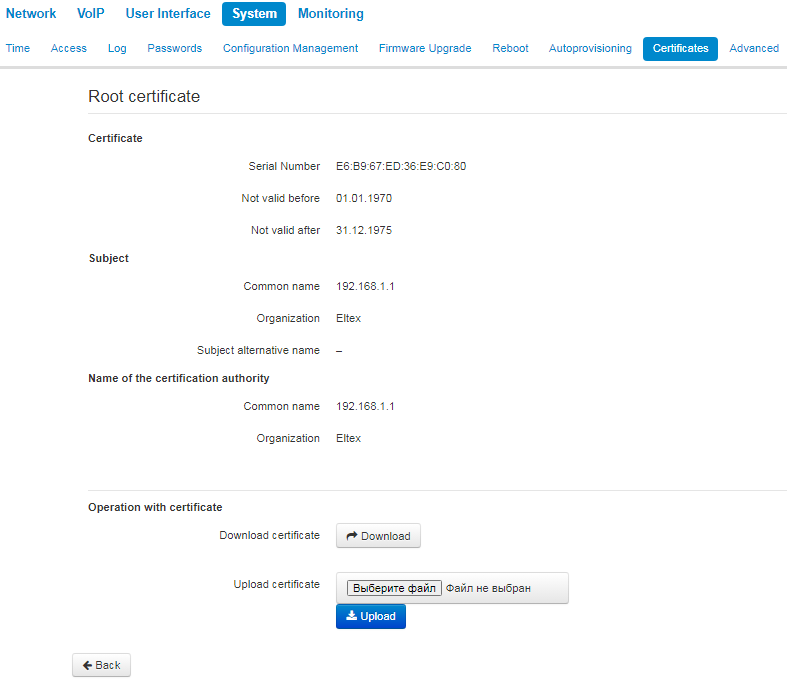
- Certificate — information about certificate:
Serial Number — serial number of the selected certificate;
— valid-from date;
Not valid after — valid-to date;
Subject — information about the certificate recipient (common name, organization, subject alternative name);
Name of the certification authority — information about the certification authority (common name, organization).
- Operation with certificate — possible actions to be done with the certificate:
- Download certificate — to save the certificate click 'Download' button;
- Upload certificate — to update the current certificate choose the file by clicking 'Select file' and then click 'Upload'.
Client certificate
Client certificate is used with outbound connections via SIP with use of TLS.
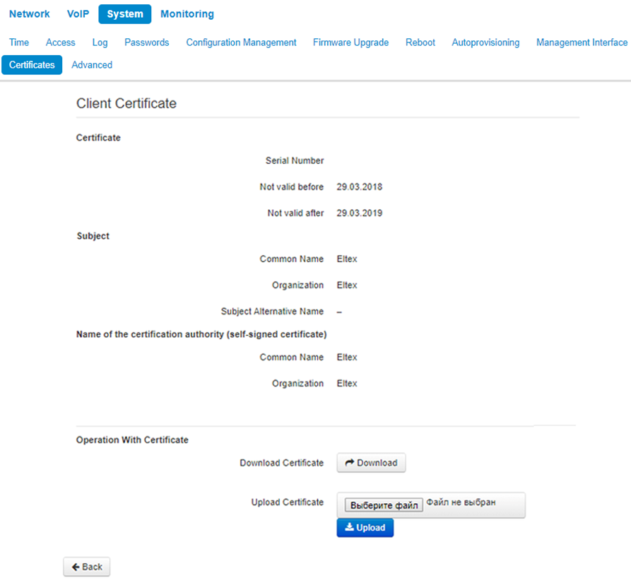
- Certificate — information about certificate:
Serial Number — serial number of the selected certificate;
— valid-from date;
Not valid after — valid-to date;
Subject — information about the certificate recipient (common name, organization, subject alternative name);
Name of the certification authority — information about the certification authority (common name, organization).
- Operation with certificate — possible actions to be done with the certificate:
- Download certificate — to save the certificate click 'Download' button;
- Upload certificate — to update the current certificate choose the file by clicking 'Select file' and then click 'Upload'.
Web certificate
Web certificate is used when accessing to the device web configurator via HTTPS.
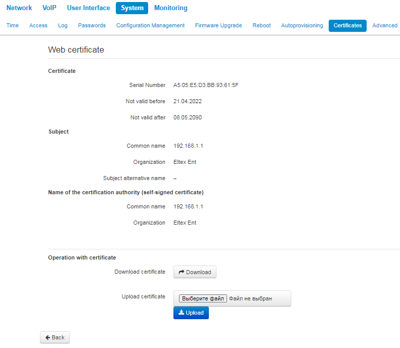
- Certificate — information about certificate:
Serial Number — serial number of the selected certificate;
— valid-from date;
Not valid after — valid-to date;
Subject — information about the certificate recipient (common name, organization, subject alternative name);
Name of the certification authority — information about the certification authority (common name, organization).
- Operation with certificate — possible actions to be done with the certificate:
- Download certificate — to save the certificate click 'Download' button;
- Upload certificate — to update the current certificate choose the file by clicking 'Select file' and then click 'Upload'.
"Advanced" submenu
Use the menu to configure additional device settings.

Reserved VLAN ID
Reserved VLAN IDs are required for solving intrasystem tasks of the gateway and can be changed depending on the VLAN ID being used for the network:
- Start VLAN ID — starting VLAN ID value in the reserved range, can take values in range [1-4090];
- End VLAN ID — ending VLAN ID value in the reserved range. This setting is unavailable for editing and calculated automatically.
Setting LLDP
- Enable LLDP — use LLDP when checked;
- LLDP transmit interval — time interval for messages transmission through LLDP. Default value is 30 seconds.
To apply a new configuration and store settings into the non-volatile memory, click 'Apply' button.To discard changes, click 'Cancel' button.