LTP-8X, LTP-4X optical line terminals
User manual
Firmware version 3.46.0 (02.11.2022)
Terms and definitions
CBR — Constant bitrate
DBA — Dynamic bandwidth allocation
ERPS — Ethernet Ring Protection Switching
FTP — File Transfer Protocol
FW — Firmware
GPON — Gigabit PON
HSI — High Speed Internet
IGMP — Internet Group Management Protocol
IP — Internet protocol
MLD — Multicast Listener Discovery
OLT — Optical Line Terminal
ONT — Optical Network Terminal
ONU — Optical Network Unit
PCB — Printed Circuit Board
SLA — Service Level Agreement
SNTP — Simple Network time protocol
SNMP — Simple Network Management Protocol
SFP — Small Form-factor Pluggable
TFTP — Trivial File Transfer Protocol
URI — Uniform Resource Identifier
VEIP — Virtual Ethernet Interface Point
Notes and warnings
Notes contain important information, tips or recommendations on device operation and setup.
Warnings are used to inform the user about situations that may cause harm to a software and hardware complex, lead to malfunction or data loss.
Additional information, clarifications.
General information
Introduction
A GPON is a network of passive optical networks (PON) type. It is one of the most effective state-of-the-art solutions for the 'last mile' issue that significantly reduces the required amount of cable and provides data transfer with downstream rate up to 2.5 Gbps and upstream rate up to 1.25 Gbps. Being used in access networks, GPON-based solutions allow end users to have access to new services based on IP protocol in addition to more common ones.
The key GPON advantage is the use of one optical line terminal (OLT) for multiple optical network terminals (ONT). OLT converts Gigabit Ethernet and GPON interfaces and is used to connect a PON network with data communication networks of a higher level.
The range of OLT GPON equipment produced by Eltex comprises of LTP-4X/LTP-8X terminals with internal Ethernet switch with RSSI function and 4/8 GPON ports respectively.
This user manual describes purpose, main technical specifications, installation order, rules of configuration, monitoring, and software update for the devices.
Purpose
The LTP-8X/4X optical line terminal is designed to establish connection with upstream equipment and provide broadband access across passive optical networks. Ethernet connection is established through Gigabit uplink and 10GBASE-X interfaces, GPON interfaces are used to connect to optical networks. Each PON interface allows connection of up to 128 subscriber optical terminals through one fibre and supports dynamic bandwidth allocation (DBA).
The following services are provided to end users:
- voice communications;
- HDTV;
- VoIP;
- high-speed access to the Internet;
- IPTV;
- video-on-demand (VoD);
- video conferencing;
- online educational and entertainment programs.
The device supports the following functions:
- dynamic bandwidth allocation (DBA);
- support for quality assurance mechanisms (QoS), Strict priority + WRR, GPON ports prioritisation for different types of traffic according to 802.1p;
- security functions;
- ONT remote control, automatic detection of new ONTs;
- FEC errors correction;
- power measurement support for signals received from each ONT (RSSI)1;
- VLAN organisation (VLAN ID range: 0–4094);
- MAC address filtering, 16000 entries in the MAC table;
- support for IGMP snooping v1/2/3, IGMP proxy;
- support for DHCP snooping, DHCP relay agent;
- support for PPPoE IA;
- support for Jumbo Frames up to 2000 bytes (supported on NTU-1 and SFP-NTU-100).
Delivery package
The standard delivery package includes:
- LTP-4X/8X optical line terminal;
- Mounting set for 19'' rack;
- RS-232 DB9(F) — DB9(F) console cable for LTP rev.B; RJ-45 — DB9(F) console cable for LTP rev.С and rev.D;
- CD with User Manual and Quick Configuration Manual (optionally);
- Power cable (if equipped with 220 V power module);
- Passport.
Technical specifications
Table 1 — Main specifications of the line terminal
Interfaces | ||
| Number of Ethernet interfaces | LTP-8X | 10 |
| LTP-4X | 6 | |
| Connector | RJ-45 | SFP |
| Data rate | 10/100/1000 Mbps duplex/half-duplex | 1000/10000 Mbps duplex |
| Standards | 10/100BASE-TХ, 1000BASE-T | 1000BASE-X, 10GBASE-X |
| Standards | IEEE 802.1D, IEEE 802.1p, IEEE 802.1Q | |
| Number of PON interfaces | LTP-8X | 8 |
| LTP-4X | 4 | |
| Connector type | SC/UPC (socket) in accordance with ITU-T G.984.2, FSAN Class B+, FSAN Class С++, SFF-8472 | |
| Transmission medium | Fibre optical cable SMF — 9/125, G.652 | |
| Standards | Digital RSSI (Received Signal Strenght Indication) | |
| Splitting ratio | 1:4, 1:8, 1:16, 1:32, 1:64, 1:128 | |
| Class B+ | Class C++ | |
| Range of coverage | 20 km | 40 km |
| Transmitter | 1490 nm DFB Laser | 1490 nm DFB Laser |
| Data rate | 2488 Mbps | 2488 Mbps |
| Average output power | +1,5..+5 dBm | +7..+10 dBm |
| Spectral linewidth with -20dB | 1.0 nm | 1.0 nm |
| Receiver | 1310 nm APD/TIA | 1310 nm APD/TIA |
| Data rate | 1244 Mbps | 1244 Mbps |
| Receiver sensitivity | -28 dBm | -32 dBm |
| Receiver optical overload | -8 dBm | -12 dBm |
| Processor | ||
| Clock frequency | 800 MHz | |
| Core quantity | 1 | |
| RAM | LTP-4X/8Х rev.B | 512 MB |
| LTP-4X/8Х rev.С | 512 MB | |
| LTP-4X/8Х rev.D | 512 MB | |
| Non-volatile memory | LTP-4X/8Х rev.B | 512 MB |
| LTP-4X/8Х rev.С | 512 MB | |
| LTP–4X/8Х rev.D | 512 MB | |
| Switch | ||
| Bandwidth | 128 Gbps | |
| MAC table | 16К entries | |
| VLAN support | up to 4K in accordance with 802.1Q | |
| Quality of Service (QoS) | 8 prioritized egress queues per port | |
| Control | ||
| Local control | CLI — Command Line Interface | |
| Remote control | CLI (SSH2, Telnet), SNMP | |
| Monitoring | СLI, SNMP | |
| Access restriction | by password, IP address, MAC address, privilege level | |
| General parameters | ||
|---|---|---|
| Power supply | AC: 150–250 V, 50 Hz
| |
| Maximum power consumption | LTP-8X rev.B | no more than 50 W |
| LTP-8X rev.C/rev.D | no more than 55 W | |
| LTP-4X rev.B | no more than 40 W | |
| LTP-4X rev.C/rev.D | no more than 50 W | |
| Operating temperature range | from -5 to +40 °C | |
| Relative humidity | up to 80 % | |
| Dimensions (W ×H × D) | 19", 1U | |
| Dimensions with installed power module: | ||
| LTP-4X/8Х rev.B | 430 × 44 × 259 mm | |
| LTP-4X/8Х rev.С | 430 × 44 × 317 mm | |
| LTP-4X/8Х rev.D | 430 × 44 × 317 mm | |
| Weight | Complete set | |
| LTP-4X/8Х rev.B | no more than 3.5 kg | |
| LTP-4X/8Х rev.С | no more than 5 kg | |
| LTP-4X/8Х rev.D | no more than 5 kg | |
| Modules | ||
| Power module | 0.5 kg | |
Compatible SFP transceivers
Correct and error-free operation of GPON interface requires exact parameters to be chosen and set for each transceiver type. This can be done only under laboratory conditions by the terminal vendor. The following table lists SFP transceivers for which seamless terminal operation is guaranteed.
DDMI (Digital Diagnostic Monitoring Interface) provides information on transceiver parameters, such as temperature, supply voltage, etc. DDMI also measures the level of ONT signal (RSSI). All compatible transceivers support this function.
Table 2 — List of compatible SFP transceivers
Vendor | SFP transceiver model | Class | DDMI |
|---|---|---|---|
NEOPHOTONICS | PTB38J0-6538E-SC | B+ | + |
NEOPHOTONICS | 38J0-6537E-STH1+ | C++ | + |
NEOPHOTONICS | 38J0-6537E-STH2+ | C++ | + |
NEOPHOTONICS | 38J0-6537E-STH3+ | C++ | + |
Ligent Photonics | LTE3680M-BC | B+ | + |
Ligent Photonics | LTE3680M-BH | B+ | + |
Ligent Photonics | LTE3680P-BC | C+ | + |
| Ligent Photonics | LTE3680P-BC+1 | C+ | + |
Ligent Photonics | LTE3680P-BH | C+ | + |
Ligent Photonics | LTE3680P-BC2 | C++ | + |
Fanghang | DLOLT43BCDS20 | B+ | + |
Fanghang | DLOLT43CCDS20 | C+ | + |
Fanghang | FH-DLT43CCDS20 | C+ | + |
| Hisense | LTE3680M-BC+ | B+ | + |
| Hisense | LTE3680P-BC+1 | C+ | + |
| Hisense | LTE3680P-BC+2 | C++ | + |
Design
Front panel
The devices have a metal housing available for 19” form-factor rack mount; housing size is 1U. The front panel layout is shown in the figures below. Tables 3 and 4 list connectors, LEDs and controls located on the front panel of the terminal.
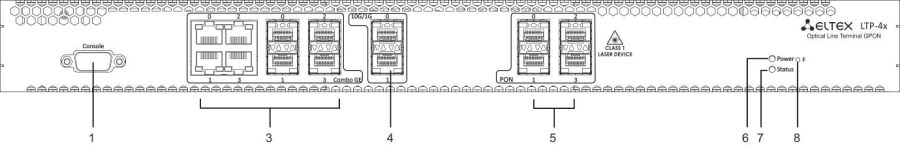
Figure 1 — LTP-4X rev.B front panel layout
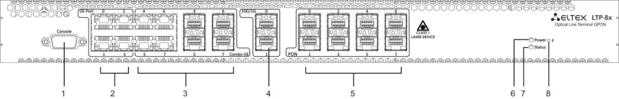
Figure 2 — LTP-8X rev.B front panel layout
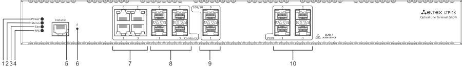
Figure 3 – LTP-4X rev.C/rev.D front panel layout
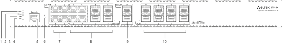
Figure 4 — LTP-8X rev.C/rev.D front panel layout
Table 3 — Description of the connectors, LEDs, and controls located on the front panel of LTP-4X/8X rev.B
# | Front panel element | Description | |
|---|---|---|---|
1 | Console | RS-232 console port for local control of the device | |
2 | GE Port 0..3 | 4 RJ-45 connectors of 10/100/1000BASE-T Gigabit uplink interfaces for connection to IP networks (for LTP-8X) | |
3 | Combo GE | 0..3 | 4 chassis for SFP modules of 1000BASE-X uplink interface for connection to IP networks (for LTP-4X) |
4 RJ-45 connectors of 10/100/1000BASE-T Gigabit uplink interfaces for connection to IP networks (for LTP-4X) | |||
4..7 | 4 chassis for SFP modules of 1000BASE-X uplink interface for connection to IP networks (for LTP-8X) | ||
4 RJ-45 connectors of 10/100/1000BASE-T Gigabit uplink interfaces for connection to IP networks (for LTP-8X) | |||
4 | 10G/1G 0..1 | 2 chassis for SFP modules of 10GBase/1000BASE-X uplink interface for connection to IP networks | |
5 | PON | 4 chassis for SFP modules of xPON 2.5 G (for LTP-4X) | |
8 chassis for SFP modules of xPON 2.5 G (for LTP-8X) | |||
6 | Power | Device power indicator | |
7 | Status | Device operation indicator | |
8 | F | Functional key that reboots the device and resets it to factory default configuration:
Configuring the response to a button click performs in the terminal CLI, for detailed description see Section System environment configuration. | |
Table 4 — Description of the connectors, LEDs, and controls located on the front panel of LTP-4X/8X rev.C, LTP-4X/8X rev.D
# | Front panel element | Description | |
|---|---|---|---|
1 | Power | Device power indicator | |
2 | Status | Device operation indicator | |
3 | Fan | Fan operation LED | |
4 | RPS | Redundant power supply LED | |
5 | Console | Console port for local management of the device Console cable pin assignment is shown in APPENDIX A. RS-232 NULL-MODEM CABLE PIN DESIGNATION | |
6 | F | Functional key that reboots the device and resets it to factory default configuration:
| |
7 | GE Port 0..3 | 4 RJ-45 connectors of 10/100/1000BASE-T Gigabit uplink interfaces for connection to IP networks (for LTP-8X) | |
8 | Combo GE | 0..3 | 4 chassis for SFP modules of 1000BASE-X uplink interface for connection to IP networks (for LTP-4X) |
4 RJ-45 connectors of 10/100/1000BASE-T Gigabit uplink interfaces for connection to IP networks (for LTP-4X) | |||
4..7 | 4 chassis for SFP modules of 1000BASE-X uplink interface for connection to IP networks (for LTP-8X) | ||
4 RJ-45 connectors of 10/100/1000BASE-T Gigabit uplink interfaces for connection to IP networks (for LTP-8X) | |||
9 | 10G/1G 0..1 | 2 chassis for SFP modules of 10GBase/1000BASE-X uplink interface for connection to IP networks | |
10 | PON | 4 chassis for SFP modules of xPON 2.5 G (for LTP-4X) | |
8 chassis for SFP modules of xPON 2.5 G (for LTP-8X) | |||
4 electrical Ethernet and 4 optical interfaces are combined (Combo GE 4..7). The combo ports may have only one active interface at the same time.
Rear panel
The rear panel layout of the device is depicted in Fig. 5, 6, 7.
Table below lists rear panel connectors.
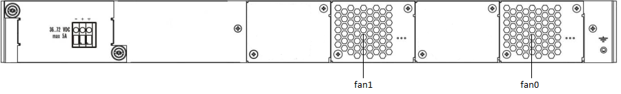
Figure 5 — LTP-4X/8X (DC) rear panel layout
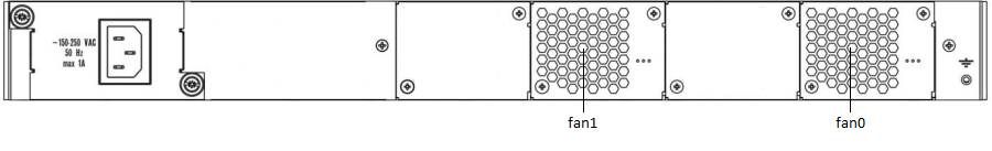
Figure 6 — LTP-4X/8X (AC) rear panel layout
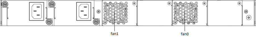
Figure 7 — Rear panel layout of LTP-4X/8X rev.C, LTP-4X/8X rev.D with two power modules
Table 5 — Rear panel connectors description
Rear panel element | Description |
|---|---|
36 .. 72 VDC, max 5A | Connector for DC power supply |
160–250 VAC, 50 Hz, max 1A | Connector for AC power supply |
Fan0, Fan1 | Ventilation units |
Earth bonding point | Earth bonding point |
Light indication
The indicators located on the front panel show the status of the terminal. Indicator states are listed in Tables 6 and 7.
Table 6 — LTP-4X/8X rev.B status light indication
LED name | Indicator state | Device state |
|---|---|---|
Power | Off | Power is off |
Solid green | Power is on, normal device operation | |
Status | Flashes green | Normal operation |
Flashes red | Critical failure |
Table 7 — LTP-4X/8X rev.C/rev.D status light indication
LED name | Indicator state | Device state |
|---|---|---|
Power | Solid green | Power is on, normal device operation |
Off | Power is off | |
Red | The primary source of the main power supply is unavailable (in case the device is connected to a redundant power supply) or the main power supply failed | |
Status | Flashes green | Normal operation |
Flashes red | Critical failure | |
Fan | Solid green | All fans are operational |
Solid red | One or more fans are failed | |
RPS | Solid green | Redundant power supply is connected and operates correctly |
Disabled | Redundant power supply is not connected | |
Red | The primary source of the redundant power supply is unavailable or the redundant power supply failed |
Temperature sensors
2 temperature sensors are used to measure temperature inside the terminal case.
Figure below shows the sensor location on PCB.
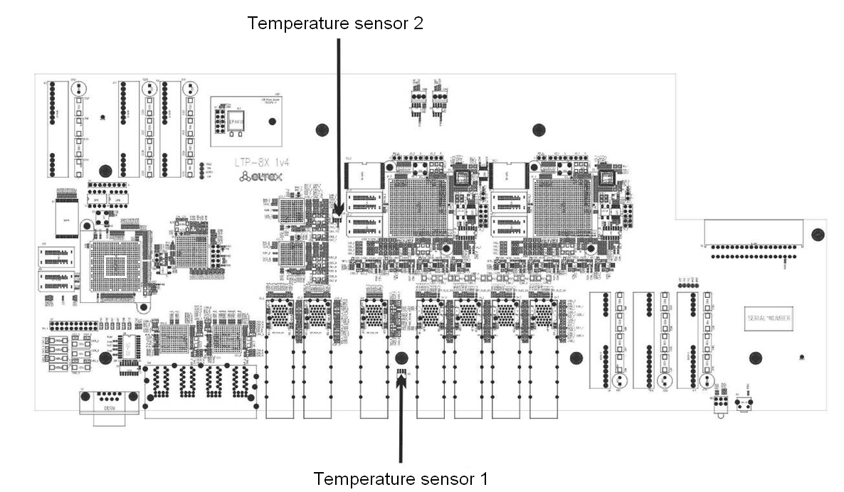
Figure 8 — Temperature sensors allocation
Ventilation system
There are ventilation openings on the device rear, front and side panels that serve to remove heat. The rear panel has two ventilation units installed (Figure 5, Figure 6 and Figure 7).
Air flows in through the perforated front and side panels, circulates through all internal components, cools them down, and then it is removed by fans located on the perforated rear panel.
The device contains 2 fans. The ventilation units are detachable. The procedure for assembly and dismantling is described in Ventilation Units Replacement.
Safety rules and installation procedure
This chapter describes how to install the terminal in a rack and connect it to the power supply.
Safety requirements
General requirements
Any operations with the equipment should comply to the "Safety Regulations for Operation of Consumer's Electrical Installations".
Operations with the terminal should be carried out only by personnel authorised in accordance with the safety requirements.
- Before operating the device, all engineers should undergo special training.
- The terminal should be connected only to properly functioning supplementary equipment.
- The device could be permanently used under the following conditions:
- ambient temperature from -5 to +40 °C;
- relative humidity up to 80 % at +25 °C;
- atmosphere pressure from 6.0×10⁴ to 10.7×10⁴ Pa (from 450 to 800 mm Hg).
- The terminal should not be exposed to mechanical shock, vibration, smoke, dust, water, and chemicals.
- To avoid components overheating which may result in device malfunction, do not block air vents or place objects on the equipment.
Electrical safety requirements
- Prior to connecting the device to a power source, ensure that the equipment case is grounded with an earth bonding point. The earthing wire should be securely connected to the earth bonding point. The resistance between the earth bonding point and earthing busbar should be less than 0.1 Ω. Any PC and measurement instruments should be properly grounded prior to their connection to the terminal. The potential difference between the equipment case and the cases of the instruments should be less than 1 V.
- Prior to turning the device on, ensure that all cables are undamaged and securely connected.
- Make sure the device is off, when installing or removing the case.
- Power modules of LTP-X rev.B should be replaced only when the device is powered off. Follow the procedure in Terminal installation. Power modules of LTP-X rev.C/rev.D terminals can be installed and removed without powering the device off.
- Follow the instructions given in SFP transceivers replacement to install or remove SFP transceivers. This operation does not require the terminal to be turned off.
Terminal installation
Check the device for visible mechanical damage before installing and turning it on. In case of any damage, stop the installation, fill in a corresponding document and contact your supplier. If the terminal was exposed to low temperatures for a long time before installation, leave it for 2 hours at ambient temperature prior to operation. If the device was exposed to high humidity for a long time, leave it for at least 12 hours in normal conditions prior to turning it on.
Support brackets mounting
The delivery package includes support brackets for rack installation and mounting screws to fix the terminal case on the brackets. To install the support brackets:
- Step 1. Align four mounting holes in the support bracket with the corresponding holes in the side panel of the device.
- Step 2. Use a screwdriver to screw the support bracket to the case.
- Step 3. Repeat steps 1 and 2 for the second support bracket.
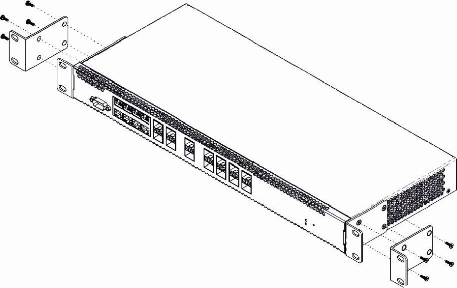
Figure 9 — Support brackets mounting
Terminal rack installation
To install the terminal to the rack:
- Step 1. Attach the terminal to the vertical guides of the rack.
- Step 2. Align mounting holes in the support bracket with the corresponding holes in the rack guides. Use the holes of the same level on both sides of the guides to ensure the device horizontal installation.
- Step 3. Use a screwdriver to screw the terminal to the rack.
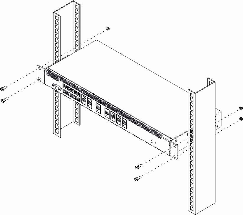
Figure 10 — Device rack installation
The terminal is horizontally ventilated. The side panels have air vents. Do not block the air vents to avoid components overheating and subsequent terminal malfunction.
To avoid overheating and provide necessary ventilation of the terminal, sufficient space should be provided above and below the terminal, not less than 10 cm.
Power module installation
Depending on power supply requirements, the LTP-4X/8X rev.B terminals can be supplemented with either an AC power module, 220 V, 50 Hz, or a DC power module, 48 V. Location of the power module is shown in Figure 11.
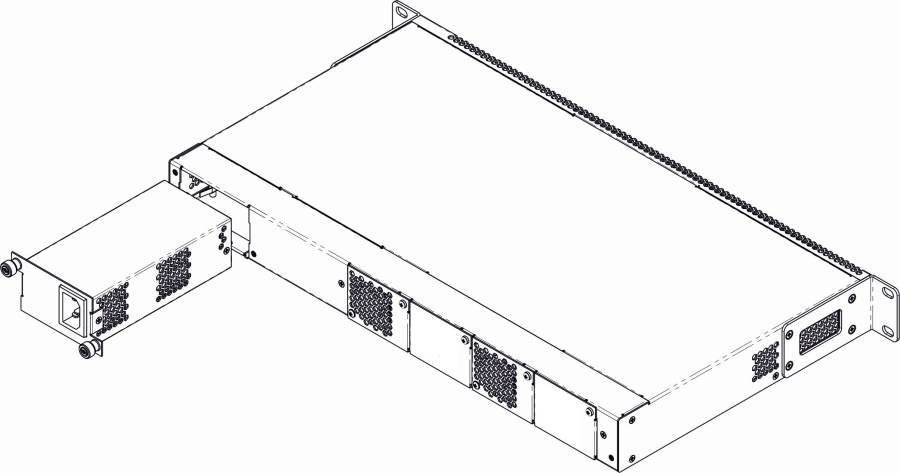
Figure 11 — Power module installation
The LTP-4X rev.C/rev.D and LTP-8X rev.C/rev.D terminals can use one or two power modules. The second power module installation is necessary when greater reliability is required. In case of using two power modules, it is allowed to use different power plants for supplying (with different voltage).
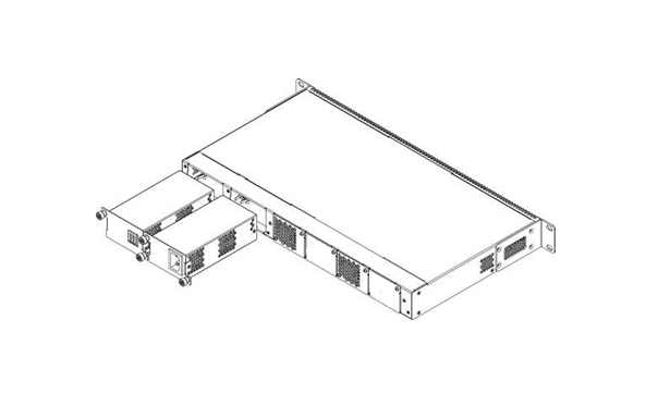
Figure 12 — Power module installation for LTP rev.C/rev.D
From the electric point of view, both places for power module installation are identical. In the context of device operation, the power module located closer to the edge is considered as the main module, and the one closer to the centre — as the backup module. Power modules can be inserted and removed without powering the device off. When additional power module is inserted or removed, the terminal continues operation without reboot.
To install a power module:
- Step 1. Install the power module into the socket shown in Fig. 11 or Fig. 12.
- Step 2. Screw the module to the case.
- Step 3. Follow the instructions in Terminal installation to power on.
The device installation order:
- Step 1. Mount the device. In case of installation to a 19" form-factor rack, mount the support brackets from the delivery package to the rack.
- Step 2. Ground the case of the device. This should be done prior to connecting the device to the power supply. An insulated multiconductor wire should be used for earthing. The device grounding process and the earthing wire section should comply with Electric Installation Code. The earth bonding point is located on the rear panel, see Figure 5, Figure 6 and Figure 7.
- Step 3. If you intend to connect a PC or another device to the switch console port, the device must be properly grounded as well.
- Step 4. Connect the power supply cable to the device.
- Step 5. Turn the device on and check the front panel LEDs to make sure the terminal is in normal operating conditions.
Getting started with the terminal
Connecting to the terminal CLI
This chapter describes various connection methods for Command Line Interface (CLI) of the terminal.
A serial port (hereafter — COM port) is recommended to use for the initial configuration of the terminal.
Connecting to CLI via COM port
This type of connection requires PC either to have an integrated COM port or to be supplied with an USB-COM adapter cable. The PC should also have a terminal program installed, e. g. Hyperterminal.
- Step 1. Use the null modem cable from the delivery package to connect the console port of the terminal to the PC COM port as shown in figure below.
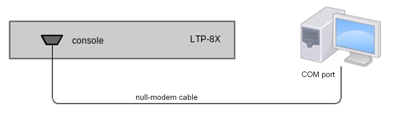
Figure 13 — Connecting the terminal to a PC via COM port
Step 2. Launch the terminal program and create a new connection. Select the corresponding COM port in the Connect to drop-down list. Assign the port settings according to the table below. Click <OK>.
Table 8 — Port specificationsParameter Value Speed 115200 Data bits 8 Parity No Stop bits 1 Flow control None Step 3. Press <Enter>. Log into the terminal CLI.
Factory authorization settings:
login: admin, password: password.******************************************** * Optical line terminal LTP-8X rev.D * ******************************************** LTP-8X login: admin Password: ******** Eltex LTP-8X-rev.D software version 3.40.0 build 2358 on 10.12.2020 15:32 Technical support: https://eltex-co.ru/support Mon Dec 28 10:56:29 LOCAL 2020 LTP-8X#
Connecting to CLI via Telnet protocol
The Telnet protocol connection is more universal than the connection via COM port. Connection to CLI can be established directly at the terminal location or via an IP network with the help of a remote desktop.
This section considers direct connection to CLI at the terminal location. Remote connection is similar, but requires changes in the terminal IP address that will be considered in detail in the Network Settings section.
In order to be connected to the terminal, a PC should have a Network Interface Card (NIC). Additionally you will need a network cable (Patching Cord RJ-45) of the required length, as it is not included in the
terminal delivery package.
- Step 1. Connect one end of the network cable to any "GE Port" or "Combo GE" port of the terminal. Connect another end to NIC on the PC as shown in the figure below.
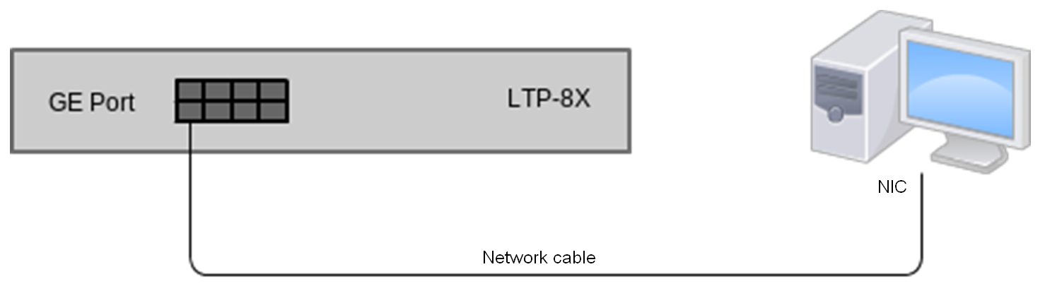
Figure 14 — Connecting the terminal to a PC via network cable
- Step 2. Assign IP settings for network connections. Set 192.168.1.1 as an IP address and 255.255.255.0 as a subnet mask.
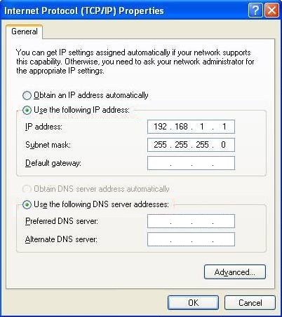
Figure 15 — Network connection configuration
- Step 3. On the PC, click Start > Run. Enter the telnet command and the terminal's IP address. The factory setting for the IP address is 192.168.1.2. Click <OK>.
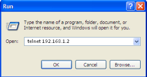
Figure 16 — Telnet client startup
Step 4. Log into the terminal CLI.
Factory authorization settings:
login: admin, password: password.Trying 192.168.1.2... Connected to 192.168.1.2. Escape character is ’^]’. ******************************************** * Optical line terminal LTP-8X rev.D * ******************************************** login: admin Password:******** Eltex LTP-8X-rev.D software version 3.40.0 build 2358 on 10.12.2020 15:32 Technical support: https://eltex-co.ru/support Mon Dec 28 10:56:29 LOCAL 2020
Connecting to CLI via Secure Shell protocol
Secure Shell connection (SSH) has functionality similar to the Telnet protocol. However, as opposed to Telnet, Secure Shell encrypts all traffic data, including passwords. This enables secure remote connection via public IP networks.
This section considers direct connection to CLI at the terminal location. Remote connection is similar, but requires changes in the terminal IP address that will be considered in detail in the Network Settings section.
In order to be connected to the terminal, a PC should have a Network Interface Card (NIC). The PC should have an SSH client installed, e. g. PuTTY. Additionally you will need a network cable (Patching Cord RJ-45) of the required length, as it is not included in the terminal delivery package.
- Step 1. Perform steps 1 and 2 from the Connecting to CLI via COM port section.
- Step 2. Run PuTTY. Enter IP address of the terminal. The factory setting for the IP address is 192.168.1.2. Select port 22 and SSH protocol type. Click <Open>.
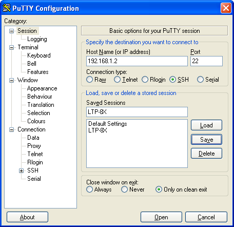
Figure 17 — SSH client startup
Step 3. Log into the terminal CLI. Factory authorization settings:
login: admin, password: password.login: admin Password: ******** Eltex LTP-8X-rev.D software version 3.40.0 build 2358 on 10.12.2020 15:32 Technical support: https://eltex-co.ru/support Mon Dec 28 10:56:29 LOCAL 2020 LTP-8X#
Getting started with terminal CLI
CLI is the main means of communication between user and the terminal. This chapter considers general operations in CLI: commands grouping, automatic code completion, and history.
CLI views hierarchy
Views are used in the terminal CLI to group commands and optimize their length.
Figure 18 shows a graphic chart of main views and the commands to switch between them.
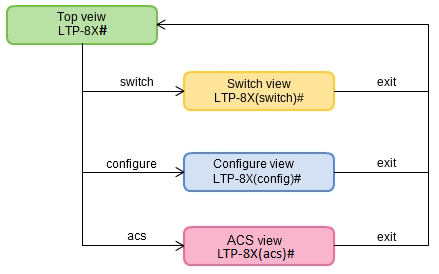
Figure 18 — CLI mode hierarchy
- The Top view includes general commands, which refer to the device in general. For example: view terminal parameters, firmware update, reboot, etc.;
- The Switch configure view groups commands related to the switch: VLAN, GE interfaces, LACP and others;
- The Configure view is a list of terminal configuration commands. E.g. user management, services configuration, GPON interface and ONT configuration, profile configuration, etc.
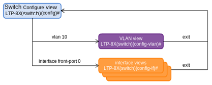
Figure 19 — Switch view hierarchy
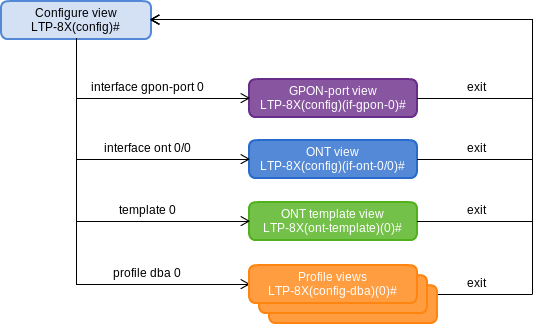
Figure 20 — Configure view hierarchy
Figure 20 shows the Configure view, which consists of four parts:
- The GPON-port view is used to configure GPON interfaces;
- The ONT view is used to configure the ONT;
- ONT configuration templates are modified in the ONT template view;
- The profile of the terminal configuration is configured in the Profile view.
CLI hotkeys
In order to speed up the operations with the command line, the following hotkeys have been added:
Hotkey | Result |
|---|---|
Ctrl+C | Termination of the current operation; clear line |
Ctrl+D | Transition up one level |
Ctrl+Z | Transition to root section |
Ctrl+A | Transition to the beginning of line |
Ctrl+E | Transition to the end of line |
Ctrl+U | Removal of characters to the left of a cursor |
Ctrl+К | Removal of characters to the right of a cursor |
Ctrl+W | Remove a word |
Ctrl+B | Transition of a cursor one position backwards |
Ctrl+F | Transition of a cursor one position ahead |
CLI automatic command completion
In order to make work with CLI faster and easier, an automatic command completion is implemented. A good knowledge of CLI command system allows user to work with CLI as fast as with graphical interface.
For example, enter the ex command in the Top view and press <Tab>.
LTP-8X# ex<Tab>
LTP-8X# exit
As this view has only one command with the ex prefix, CLI automatically completes it.
If there are several commands with this prefix, CLI shows hints with possible options.
LTP-8X# co<Tab>
commit configure copy
LTP-8X# con<Tab>
LTP-8X# configure
CLI command history
Sometimes it might be necessary to execute the same set of operations several times. To make the work with repeating commands easier, the terminal CLI keeps the command history.
The list of previously entered commands can be displayed by using the show history command.
LTP-8X# show history
Last CLI commands:
show version
configure terminal
exit
show history
LTP-8X#
Use the <Up> and <Down> cursor keys to scroll the command history and the <Enter> key to execute the selected command.
LTP-8X# <Up>
LTP-8X# show management <Up>
LTP-8X# switch <Up>
LTP-8X# exit <Up>
LTP-8X# show uptime <Enter>
up 1 day, 23:44
Group operations
Group operations can be performed on such terminal configuration objects as interfaces and ONT. It is especially convenient, when you have to apply the same actions to multiple objects.
To perform a group operation, select the range of object IDs instead of one object ID. This feature is supported by a majority of CLI commands.
For example, enable fec for all ONTs in a certain channel.
LTP-8X(config)# interface ont 0/0-127
LTP-8X(config)(if-ont-0/0-127)# fec
Or view the list of active ones in the first 4 GPON channels.
LTP-8X# show interface ont 0-3 ont online

GPON-port 0 has no online ONTs
GPON-port 1 has no online ONTs
GPON-port 2 has no online ONTs
GPON-port 3 has no online ONTs

Total ONT count: 0
Configuring the terminal
Terminal configuration
A collection of all terminal settings is referred to as configuration. This chapter provides information on the parts which configuration consists of. It also defines lifecycle of configuration and describes main operations, which can be performed.
Configuration structure
The terminal configuration can be conventionally divided into 3 parts. Figure below shows the configuration structure.
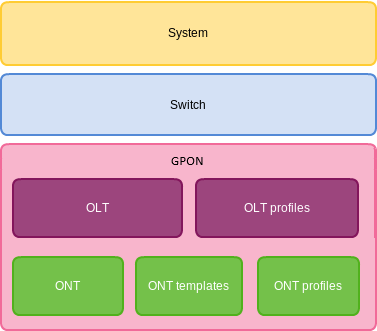
Figure 21 — Terminal configuration structure
System is a general system part. This group includes such settings as: network, service settings, user table, etc.
Switch represents a switch configuration. This group includes configuration parameters for Ethernet interfaces of the front panel, as well as VLAN settings.
GPON contains 5 subparts:
- OLT — GPON OLT and GPON interface settings;
- OLT profiles — OLT profile part consists of address table profiles, VLAN profiles, DHCP RA and PPPoE IA profiles;
- ONT — ONT configuration base;
- ONT templates — ONT templates;
- ONT profiles — ONT profiles.
Configuration lifecycle
The terminal configuration may have the following states:
- RUNNING— active configuration. It refers to the current configuration of the terminal;
- CANDIDATE— an edited configuration;
- NVRAM — a configuration stored in non-volatile memory. This configuration will be used as RUNNING after the device is loaded.
The RUNNING configuration is loaded to a new CLI session and becomes available for review (CANDIDATE). After changing the configuration (CANDIDATE) in the CLI session, user can either enter the commit command to accept the changes or use the rollback command to discard the changes and apply the current (RUNNING) configuration. The save command saves the RUNNING configuration into NVRAM of the terminal.
Figure below shows a chart of configuration lifecycle.
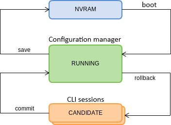
Figure 22 — Configuration lifecycle of the terminal diagram
Configuration autosave
In some cases, for example, when several operators are working on the terminal or the terminal is automatically configured through OSS/BSS, it may be convenient to organize a centralized saving of the configuration into NVRAM at a specified time or at a specified time interval. The terminal allows this with the help of a configuration autosave mechanism.
For daily autosave of the configuration, define a time when autosave should be implemented.
LTP-8X(config)# config autosave hour 3 minute 44
For autosave at specified time intervals, define the interval in seconds.
LTP-8X(config)# config autosave period 3600
Check the entered data by using the do show config command.
LTP-4X(config)# do show config
	Config:
		Daily autosave: at 03:44
		Periodic autosave: every 3600 seconds
	   LTP-4X(config)#
For disabling a mode, use the no command.
LTP-4X(config)# no config autosave hour
LTP-4X(config)# no config autosave period
Apply the changes.
LTP-8X(config)# do commit
Creating a configuration backup
Configuration backups allow the terminal operation to be quickly restored after abnormal situations or replacement. Manual or triggered (on events) creation of backups is recommended at a regular basis.
Terminal configuration is uploaded to a TFTP server which is available in the management network. The copy command is used to upload the data. Pass the uploaded terminal configuration fs://config and destination URI as parameters.
LTP-8X# copy fs://config tftp://192.168.1.1/config
Upload backup file to TFTP-server..
Configure a triggered upload to create backups automatically.
Step 1. Go to the configure view and select the URI of the configuration backup.
LTP-8X# configure terminal
LTP-8X(config)# backup uri tftp://192.168.1.1/config
Step 2. The terminal can be adjusted to upload configuration every time the configuration is saved if necessary.
LTP-8X(config)# backup on save
Step 3. The terminal can be adjusted to use a timer for configuration upload if necessary. In this case, additionally set the timer period in seconds.
LTP-8X(config)# backup on timer
LTP-8X(config)# backup timer period 3600
Step 4. Check the entered data by using the do show backup command.
LTP-8X(config)# do show backup
Tftp:
		Backup on conf save: enabled
		Backup on timer: enabled
		Backup on timer period: 3600
		Backup uri: ’tftp://192.168.1.1/config’
Step 5. Apply the changes.
LTP-8X(config)# do commit
Configuration restore
The terminal configuration is restored from the TFTP/FTP/HTTP server which is available in the management network. The copy command is used to restore the data. Define source URI as parameter and fs://config as restored configuration.
LTP-8X# copy tftp://10.0.105.1/config fs://config
	Download file from TFTP-server..
	Reading of the configuration file..
	Configuration have been successfully restored (all not saved changes was lost)
Configuration reset
To reset a terminal configuration to factory settings, use the default command.
LTP-8X# default
	Do you really want to set up default configuration? (y/n) y
	Configuration have been reseted to default.

	Terminal will be reloaded.
Resetting a configuration of a remote terminal also resets network settings. The terminal will not be available for operation until the network settings are reconfigured.
Network settings
This chapter describes adjustment of network settings for the terminal. Adjusting network settings enables remote control and integration with OSS/BSS systems.
Network parameters configuration
It is recommended to adjust network settings via COM port connection. This will prevent issues with connection loss upstream the terminal being adjusted. Be very careful when using remote adjustment.
Step 1. Use the show management command to view the current network settings.
LTP-8X# show management
Network:
	Hostname: ’LTP-8X’
	Ipaddr: 192.168.1.2
	Netmask: 255.255.255.0
	Vlan management: 1
	Gateway: 0.0.0.0
	Vlan prio: 7
	Dscp: 63
	Additional vlan: <list is empty>
Step 2. Switch to the configure view. Set the terminal name by using the hostname command.
LTP-8X# configure terminal
LTP-8X(config)# hostname LTP-8X-1
Step 3. Set the terminal IP address by using the management ip command.
LTP-8X(config)# management ip 10.0.0.1
Step 4. Set the subnet mask by using the management mask command.
LTP-8X(config)# management mask 255.0.0.0
Step 5. Set the default gateway by using the management gateway command.
LTP-8X(config)# management gateway 10.0.0.254
Step 6. Set the management VLAN of the terminal by using the management vid command if necessary. Use the management cos command to set the P-bit parameter for the management VLAN.
LTP-8X(config)# management vid 9
LTP-8X(config)# management cos 5
Proper operation of the inband management function requires VLAN adjustment in the switch view as described in VLAN configuration.
Step 7. Set MAC address aging time by using the gpon network mac-age-time command.
Pass the time in seconds as a parameter.
LTP-8X(config)# gpon network mac-age-time 7200
Step 8. The network settings will change as soon as the configuration is applied. No terminal reboot is needed.
LTP-8X(config)# do commit
User management
This chapter is devoted to management of the terminal users.
The factory settings provide only one user, i. e. the device administrator.
login: admin
password: password
When starting to configure the terminal, it is recommended to change the password of the 'admin' user.
For security reasons, there is a strictly defined set of permissions, which can be delegated to terminal users. For these purposes, each user gets his own level of privileges. Level 0 corresponds to a minimum set of permissions, Level 15 — to a maximum set of permissions.
CLI commands are ranked by the level of privileges. Level 0 commands are available to all users. Level 15 commands are available only to Level 15 users. Thus, the level of commands available to a user does not exceed the user's level.
The levels of privileges can be modified as required.
Step 1. Check the current settings of privileges by using the show privileges command.
LTP-8X# show privileges
		Level 			Privileges

		0				!, exit

		1				view-ont

		2				ont-operation

		3				view-ont, ont-operation

		4				view-ont, config-ont
						ont-operation

		5				view-gpon, view-ont
						view-ont-profile, ont-operation

		6				view-gpon, view-ont
						view-ont-profile, config-gpon
						ont-operation, config-ont-profile

		7				view-switch, view-gpon
						view-ont, view-ont-profile
						view-switch-interfaces

		8				view-switch, view-gpon
						view-ont, view-ont-profile
						view-switch-interfaces, config-switch
						config-switch-interfaces
		9				view-switch, view-gpon
						view-ont, view-ont-profile
						view-switch-interfaces, config-switch
						config-gpon, config-ont
						ont-operation, config-ont-profile
						config-switch-interfaces

		10				view-switch, view-alarm
						view-system, view-general
						view-gpon, view-ont
						view-ont-profile, view-switch-interfaces

		11 				view-switch, view-alarm
						view-system, view-general
						view-gpon, view-ont
						view-ont-profile, view-switch-interfaces
						config-alarm, config-system
						config-general

		12				view-switch, view-alarm
						view-system, view-general
						view-gpon, view-ont
						view-ont-profile, view-switch-interfaces
						config-switch, config-alarm
						config-system, config-general
						config-switch-interfaces

		13				view-gpon, view-ont
						view-ont-profile

		14				—

		15				view-switch, view-alarm
						view-system, view-general
						view-gpon, view-ont
						view-ont-profile, view-switch-interfaces
						config-switch, config-alarm
						config-system, config-general
						config-gpon, config-ont
						ont-operation, config-ont-profile
						config-switch-interfaces
Step 2. Switch to the configure view. Set the required permissions corresponding to the level by using the privilege command, e. g. set permissions allowing Level 1 to view configuration of the internal switch.
LTP-8X# configure terminal
LTP-8X(config)# privilege 1 view-switch
Step 3. Settings of privileges will be applied immediately. No terminal reboot is needed.
LTP-8X(config)# do commit
The list of operations and the default levels are shown in the table below.
Table 9 — Permissions and the required level of privileges
Level
Privileges
0
!, exit
1
view-ont
2
ont-operation
3
view-ont, ont-operation
4
view-ont, config-ont, ont-operation
5
view-gpon, view-ont, view-ont-profile, ont-operation
6
view-gpon, view-ont, view-ont-profile, config-gpon, ont-operation, config-ont-profile
7
view-switch, view-gpon, view-ont, view-ont-profile, view-switch-interfaces
8
view-switch, view-gpon, view-ont, view-ont-profile, view-switch-interfaces, config-switch, config-switch-interfaces
9
view-switch, view-gpon, view-ont, view-ont-profile, view-switch-interfaces, config-switch, config-gpon, config-ont, ont-operation, config-ont-profile, config-switch-interfaces
10
view-switch, view-alarm, view-system, view-general, view-gpon, view-ont, view-ont-profile, view-switch-interfaces,
11
view-switch, view-alarm, view-system, view-general, view-gpon, view-ont, view-ont-profile, view-switch-interfaces, config-alarm, config-system, config-general
12
view-switch, view-alarm, view-system, view-general, view-gpon, view-ont, view-ont-profile, view-switch-interfaces, config-switch, config-alarm, config-system, config-general, config-switch-interfaces
13
view-gpon, view-ont, view-ont-profile
14
—
15
view-switch, view-alarm, view-system, view-general, view-gpon, view-ont, view-ont-profile, view-switch-interfaces, config-switch, config-alarm, config-system, config-general, config-gpon, config-ont, ont-operation, config-ont-profileconfig-switch-interfaces
User list preview
To view the list of terminal users, enter the show users config command.
LTP-8X(config)# do show users config
    ##                Name      Privilege
     1                root           15
     2               admin           15
     3              remote           15
The admin, root and remote users always exist and cannot be deleted or duplicated. The terminal supports up to 16 users.
Adding a new user
In order to operate effectively and safely, the terminal, as a rule, requires one or several additional users. To add a new user, enter the user command in the configure view.
LTP-8X(config)# user operator
LTP-8X(config)# do show users config
    ##                Name      Privilege
     1                root           15
     2               admin           15
     3              remote           15
     4            operator            0
LTP-8X(config)#
Pass the name of the new user to the user command as a parameter. The name should not be longer than 32 characters. The name should not contain special characters.
Changing user password
To change user password, enter the user command. Pass the user name and a new password as parameters.
LTP-8X(config)# user operator password newpassword
The password should not be longer than 31 characters and shorter than 8 characters. If the password contains a space, use quotations for the password.
Viewing and changing user access rights
To manage user access rights, a user priority system is implemented. A newly created user is granted with a minimal set of permissions.
LTP-8X(config)# user operator
LTP-8X(config)# do show users config
    ##                Name      Privilege
     1                root           15
     2               admin           15
     3              remote           15
     4            operator            0
LTP-8X(config)#
To change the user priority level, enter the user command. Pass the user name and a new priority as parameters.
LTP-8X(config)# user operator priviledge 15
LTP-8X(config)# do show users config
    ##                Name      Privilege
     1                root           15
     2               admin           15
     3              remote           15
     4            operator           15
LTP-8X(config)#
Deleting a user
To delete a user, enter the no user command in the configure view. Pass the user name as a parameter.
LTP-8X# configure terminal
LTP-8X(config)# no user operator
ААА configuration
This chapter describes configuring of services and protocols related to authentication, authorization and accounting.
Hereafter, the term 'authorization' means authorization of the commands — definning rights for executing commands on a remote server.
Authorization of a user — a process of obtaining a specified permission set, combined with authentication process.
LTP-X supports radius and tacacs+ AAA protocols. Below is a table of the functionality of these protocols.
Table 10 — Permissions and the required level of privileges
Function and protocol | Tacacs+ | Radius |
|---|---|---|
Authentication | + | + |
Authorization | + | - |
Accounting start-stop | + | + |
Accounting commands | + | - |
Configuring servers
The principles of servers configuration are common for supported protocols. You can configure an IP address, key, response timeout and a data exchange port for each server. You can set up to 3 servers for the RADIUS. The LTP will apply to the servers according to their priorities. If the priority is not set, the 0 priority (the highest) will be used by default.
Step 1. Configure IP address of radius/tacacs+ server.
LTP-8X# configure terminal
LTP-8X(config)# radius-server host 10.10.10.1 priority 0
LTP-8X(config)# radius-server host 10.10.10.2 priority 1
LTP-8X(config)# radius-server host 10.10.10.3 priority 2
LTP-8X(config)# tacacs-server host 10.10.10.4
Step 2. Define an encryption key used while data exchange with the server.
LTP-8X(config)# radius-server key 12345678-r0
LTP-8X(config)# radius-server key 12345678-r1 priority 1
LTP-8X(config)# radius-server key 12345678-r2 priority 2
LTP-8X(config)# tacacs-server key 12345678
Step 3. Define server response timeout.
LTP-8X(config)# radius-server timeout 3
LTP-8X(config)# radius-server timeout 3 priority 1
LTP-8X(config)# radius-server timeout 3 priority 2
LTP-8X(config)# tacacs-server timeout 3
Step 4. Define a port for data exchange with the server (if necessary).
LTP-8X(config)# radius-server port 50005
LTP-8X(config)# radius-server port 50006 priority 1
LTP-8X(config)# radius-server port 50007 priority 2
LTP-8X(config)# tacacs-server port 50008
Step 5. Apply the changes.
LTP-8X(config)# do commit
AAA methods configuration
By default, every AAA function is implemented locally — local user data base is used for authentication and authorization, accounting via a remote server is disabled.
For using of configured in previous steps servers, define a method of a function performing.
Step 1. Select an authentication method.
LTP-8X# configure terminal
LTP-8X(config)# aaa authentication radius
Step 2. Select an authorization method.
LTP-8X# configure terminal
LTP-8X(config)# aaa authorization tacacs+
Step 3. Select a CLI session start/stop accounting method.
LTP-8X# configure terminal
LTP-8X(config)# aaa accounting start-stop radius
Step 4. Select a method of commands accounting.
LTP-8X# configure terminal
LTP-8X(config)# aaa accounting commands tacacs+
Step 5. Apply the changes.
LTP-8X(config)# do commit
In order to disable a function, use the no command.
LTP-8X# configure terminal
LTP-8X(config)# no aaa accounting commands
In case server configured for a function unavailable or key is not defined properly, the function will be implemented locally.
Services configuration
This chapter describes configuration of integrated terminal services.
SNMPD configuration
To work with the Eltex.EMS management system, the terminal should be configured to work with Simple Network Management Protocol (SNMP).
Step 1. Switch to the configure view.
LTP-8X# configure terminal
Step 2. Enable the SNMP agent of the terminal by using the snmp enable command.
LTP-8X(config)# ip snmp enable
Step 3. Enable ACL check by using the snmp access-control command if necessary. Add the record into the whitelist by using the snmp allow command. Pass the IP address of the host which will be used to connect to the SNMP agent, as a parameter.
LTP-8X(config)# ip snmp access-control
LTP-8X(config)# ip snmp allow ip 192.168.1.13
Step 4. Configure SNMP trap replication to allow the management system to receive the traps. For example, add 2 replicators and specify to send v2 SNMP traps to 192.168.1.13 and v1 traps to 192.168.1.113. To do this, use the ip snmp traps command.
It is possible to configure several receivers of SNMP traps of the same version.
LTP-8X(config)# ip snmp traps 192.168.1.13 type v2
LTP-8X(config)# ip snmp traps 192.168.1.113 type v1
Step 5. Check the entered data by using the show ip snmp command.
LTP-8X(config)# do show ip snmp
    Snmp:
        Enabled:                                  true
        Access control:                           false
        Allow ip:                                 <list is empty>
        Traps [0]:
            Type:                                 v2
            Ipaddr:                               192.168.1.13
        Traps [1]:
            Type:                                 v1
            Ipaddr:                               192.168.1.113
        Version:                                  v2
 		Community read-only [0]:                       'QwYva0dvS3N'
        Community read-only [1]:                       'QwYva0dvS3N'
        Community read-only [2]:                       'QwYva0dvS3N'
        Community read-write [0]:                      'LQtfx9v3m9+qA=='
        Community read-write [1]:                      'LQtfx9v3m9+qA=='
        Community read-write [2]:                      'LQtfx9v3m9+qA=='
        Trap community:                                '9qXUEDwUMAg'
        Location:                                 'admin'
        Contact:                                  'admin'
        Alias:                                    <for showing use separate command>
        EngineID:                                 0x6C2A20B42CB28232FABEA8EE19
        Users:                                    <for showing use separate command>
Step 6. The settings of the SNMP agent change as soon as the configuration is applied.
No terminal reboot is needed.
LTP-8X(config)# do commit
The types and purpose of SNMP traps are closely connected with the log of active alarms.
You need to configure users to operate with SNMPv3.
Step 1. Set the version of SNMP agent to 3.
LTP-8X(config)# ip snmp version v3
Step 2. Add users and set the privilege levels.
LTP-8X(config)# ip snmp user "rwuser" auth-password "rwpass" enc-password "rwencr" access rw
LTP-8X(config)# ip snmp user "rouser" auth-password "ropass" enc-password "roencr" access ro
Step 3. Check the configuration.
LTP-8X(config)# do show ip snmp users
   SNMP users
   ~~~~~~~~~~

User name                          permissions
--------------------               ---------------
rwuser                             read-write
rouser                             read-only

2 SNMP users.
The SNMPv3 agent supports authNoPriv and authPriv methods. The encryption of the password performs according to the MD5 algorithm.
NTPD configuration
The terminal has no integrated real-time clocks with a battery. For the events in system log to show correct time and for automated operations to be performed in time, time synchronisation should be adjusted with the help of the NTP protocol.
Step 1. Switch to the configure view.
LTP-8X# configure terminal
Step 2. Enable time synchronisation by using the ip ntp enable command. Specify the IP address to be used for synchronisation in the ip ntp ip command.
LTP-8X(config)# ip ntp enable
LTP-8X(config)# ip ntp ip 192.168.1.254
Step 3. Specify the synchronisation interval in seconds by using the ip ntp interval command.
LTP-8X(config)# ip ntp interval 3600
Step 4. Use the ip ntp timezone and ip ntp daylightsaving commands to set the time zone of your region and indicate whether it should be switched to the daylight-saving time.
LTP-8X(config)# ip ntp timezone 7
LTP-8X(config)# ip ntp daylightsaving
Step 5. Check the entered data by using the do show ip ntp command.
LTP-8X(config)# do show ip ntp
    Ntp:
        Enabled:                                       true
        Ntpserver:                                     192.168.1.254
        Interval:                                      3600
        Timezone:                                      7
        Daylightsaving:                                true
LTP-8X(config)#
Step 6. Apply the configuration by using the commit command.
LTP-8X(config)# do commit
ACSD and DHCPD configuration
The terminal has an integrated auto configuration server (ACS). To ensure interaction between ONTs and ACS, ONTs should obtain IP addresses for their management interfaces. The terminal has an integrated DHCP server to solve this task. These two servers are interconnected and cannot work separately.
ACSD configuration
Step 1. Switch to the configure view.
LTP-8X# configure terminal
Step 2. Turn on the ACS server by using the ip acs server enable command.
LTP-8X(config)# ip acs server enable
Step 3. If necessary, set the IP address, server mask, and identifier of the management VLAN, which will be used to send packets between ACS and ONTs. By default, mask 21 is set, which enables 2046 hosts per network.
LTP-8X(config)# ip acs server ip 192.168.200.9
LTP-8X(config)# ip acs server mask 255.255.255.0
LTP-8X(config)# ip acs server vid 200
Step 4. In addition to HTTP, ACS can also use an extended version of this protocol that supports encryption — HTTPS. This is configured by the ip acs server scheme command.
LTP-8X(config)# ip acs server scheme http
Step 5. If necessary, configure the login and password to be used by ONTs to access the ACS server.
LTP-8X(config)# ip acs server login acs
LTP-8X(config)# ip acs server password acsacs
DHCPD configuration
Step 1. Start the DHCP server by using the ip dhcp server enable command.
LTP-8X(config)# ip dhcp server enable
Step 2. Configure the range of IP addresses to be assigned by the server with the ip dhcp server range command and specify the first and the last addresses of the range.
LTP-8X(config)# ip dhcp server range 192.168.200.10 192.168.200.150
Step 3. Set the maximum lease time in seconds, during which the server allows clients to use the addresses, by using the ip dhcp server lease-time command.
LTP-8X(config)# ip dhcp server lease-time 600
Step 4. Use the ip dhcp server option-43 command to configure output of option 43 in the DHCP offer packet for correct connection of ONTs to the ACS server. View general settings of ACSD and DHCPD to check the format of the option.
LTP-8X(config)# ip dhcp server option-43
Step 5. If necessary, configure the delivery of static routes to the network to the ONT TR-interface (option 121).
LTP-8X(config)# ip dhcp server static-route net 172.20.240.0 mask 255.255.255.0 gateway 172.20.40.1
Step 6. Check the changes by using the do show ip acs server command.
LTP-8X(config)# do show ip acs server
 ACS server:
        Enabled:                       true
        Ip:                            192.168.200.9
        Port:                          9595
        Mask:                          255.255.255.0
        Vid:                           200
        Scheme:                        'http'
        Login:                         'acs'
        Password:                      'acsacs'
        External fw ip:                0.0.0.0
        External fw port:              9595
        Local fw port:                 9696
 ACS DHCP server:
        Enabled:                       true
        Max lease time:                600
        Insert option 43:              true
        First IP:                      192.168.200.10
        Last IP:                       192.168.200.150
 DHCP option 43 (will be generated automatically):
        URL:                           'http://192.168.200.9:9595'
        Login:                         'acs'
        Password:                      'acsacs'
Step 7. Apply the configuration by using the commit command.
LTP-8X(config)# do commit
LOGD configuration
System log collects terminal history data and allows its further display. Adjustment of system log operates with such terms as module, filter level, and output device.
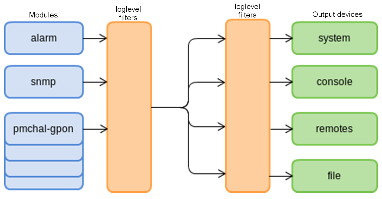
Figure 23 — Terminal system log
Messages of the system log are grouped into modules according to their functions. Configuration of the following modules is possible:
Table 11 — System log modules
Module | Description |
|---|---|
alarm | Alarms log message |
snmp | Messages from the SNMP agent |
dhcpd | Messages from the integrated DHCP server |
pmchal-ipc | Messages from the pmchal subsystem of interprocess communication |
pmchal-gpon | GPON messages |
pmchal-machine | Messages on operation of state machines for OLT, channels, and ONT |
pmchal-olt | OLT general information |
pmchal-gpon-port | Information about GPON channels |
pmchal-ont | ONT information |
pmchal-scheduler | Messages from the task scheduler subsystem |
pmchal-rdn | Messages on GPON channels reservation |
pmchal-dhcpra | Messages from DHCP Relay Agent |
pmchal-dhcpv6ra | Messages from DHCPv6 Relay Agent |
pmchal-pppoeia | Messages from PPPoE Intermediate Agent |
A filtering level and additional display information can be specified for messages of each module.
The filtering level sets the minimum importance level of the messages to be displayed in the log. The used filtering levels are listed in Table 12.
Table 12 — System log filtering levels
Level | Description |
emergency | Further operation of the system is not possible |
alert | The system requires emergency intervention |
critical | Critical events |
error | Operation errors |
warning | Warnings |
notice | Important events during normal operation |
info | Information messages |
debug | Debug messages |
none | Messages are not registered in the log |
The emergency level is the maximum level, the debug level is the minimum one.
Enabling the debug logging level increases the load on the system produced by LOGD. It is not recommended to use debug mode unless necessary.
The log subsystem allows display of the terminal operation log on different devices. All output devices can be used simultaneously.
Table 13 — System log output device
Output device | Name | Description |
|---|---|---|
System log | system | The system log allows the log to be displayed locally or with the help of the syslog server. |
Console | console | Being used for log display, the console allows system messages to be visible as soon as they are received in the terminal connected to the Console port. |
CLI sesions | rsh | Being used for log display, CLI sessions allow system messages to be visible as soon as they are received in all CLI sessions connected via telnel or SSH. |
File | file | Logging into a file allows system messages to be written directly to the file, which can be sent to support specialists for further analysis. |
The log is saved in non-volatile memory by default. The system has 4 log rotated files of 1M each. The last 3 logs are archived to gzip.
Module configuration
Consider module configuration by the example of the pmchal-gpon module responsible for messages from the GPON subsystem. Other modules have similar configuration process.
Step 1. Set the logging level using the logging module pmchal-gpon loglevel command.
LTP-8X(config)# logging module pmchal-gpon loglevel info
Step 2. To view information about modules, use the do show logging module pmchal-gpon command.
LTP-8X(config)# do show logging module pmchal-gpon
    Log:
        Submodule [pmchal-gpon]:
            Log level:                                     notice
LTP-8X(config)#
Step 3. Apply the configuration by using the commit command.
LTP-8X(config)# do commit
Configuring command logging to syslog
The system is capable to record all the user's commands to syslog. Use the following command to activate the function.
LTP-8X(config)# logging commands
Configuring the Origin parameter
The system can add an additional origin-id parameter to messages sent to the Syslog server. It will be added to the beginning of the log message.
Only one additional parameter can be used at a time.
LTP-8X(config)# logging origin-id
   hostname      The sysname will be used as the hostname field of a
                 syslog message
   string        The user defined string will be used as the hostname
                 field of syslog header
   ip            The IP address of the sending interface will be used
                 as the hostname field of a syslog message
Configuring the log storage
Use the following command to record logs to non-volatile memory.
LTP-8X(config)# logging permanent
If you add "no" before the command, the logs will be recorded to RAM. In this case, the logs will be erased after reboot.
System log configuration
Step 1. Use the logging buffer command to specify the memory size in bytes to be used for system log storage.
LTP-8X(config)# logging buffer 262144
Step 2. If necessary, use the logging remote command to specify the IP address of the remote Syslog server to be used to display system log.
LTP-8X(config)# logging remote 192.168.1.43
Step 3. Configure the output devices by using the logging command.
Every output device may have its own filtering level or have the output disabled.
For example, it is possible to change the display level for the CLI sessions, which are not connected via the RS-232 console port, to "info" and disable output to file.
LTP-8X(config)# logging rsh loglevel info
LTP-8X(config)# logging file loglevel none
Step 4. To view Syslog configuration, use the do show logging settings command.
LTP-8X(config)# do show logging settings
    Log:
        Remote syslog:                                 192.168.1.30
        Remote syslog:                                 192.168.1.31
        Remote syslog:                                 192.168.1.55:520
        Remote syslog:                                 192.168.1.33
        Size:                                          16384
        Save logs between boots:                       true
        Log input commands:                            false
        Destinations:
            System:                                    notice
            Console:                                   notice
            Remote shells:                             info
            File:                                      none
Step 5. Apply the configuration by using the commit command.
LTP-8X(config)# do commit
ALARMD configuration
ALARMD is a terminal alarms manager. Alarms manager enables troubleshooting and provides information about important events related to terminal operation.
A record in active alarms log (an event) corresponds to an event, which happened in the terminal. Types of events and their descriptions are provided in the following table.
Table 14 — Types of events in the active alarms log
Event | Description | Threshold |
|---|---|---|
ram | Free RAM size decreased to the threshold | 30 % * |
login | User tried to log in or logged in by entering the credentials | - |
config-save | User saved the configuration | - |
firmware-update | LTP-8X firmware update completed successfully/with errors | - |
duplicate-mac | Two devices with the same MAC addresses detected | - |
physical-layer-flapping | Flapping on Ethernet ports | - |
pon-gpon-port-no-ont | The first ONT connected/the last ONT disconnected on channel | - |
ont-physical-layer | ONT connected/disconnected | - |
olt-update | OLT chip firmware update completed successfully/with errors | - |
ont-update | ONT chip firmware update completed successfully/with errors | - |
gpon-port-flapping | GPON interface flapping | - |
ont-flapping | ONT flapping | - |
download | File download completed successfully/with errors | - |
battery-power | Switch ONT to battery power | - |
battery-low | ONT battery low | Set in ONT |
lan-los | ONT Ethernet port lost connection | - |
ont-config | Configuration of the connected ONT | - |
file-delete | File deleted successfully/with errors | - |
physical-layer-errors | Physical layer errors on Ethernet ports | - |
physical-layer-block | Ethernet port blocked | - |
link | Ethernet port status changed (up/down) | - |
logout | User logged out | - |
ont-dying-gasp | Dying Gasp signal received from ONT | - |
ont-rei | Remote Error Indication (REI) | - |
ont-power-off | ONT power off | - |
config-change | OLT configuration changed | - |
shutdown | SNMP agent shut down | - |
oms | OMS-MIB operation completed successfully/with errors | - |
ont-state-changed | ONT status changed | - |
ont-config-changed | ONT configuration changed | - |
gpon-port-state-changed | OLT channel configuration changed | - |
pon-alarm-gpon-port | Event related to OLT channel | - |
pon-alarm-onui | Event related to ONT | - |
ont-update-inprogress | Updating ONT firmware | - |
olt-device-reset | Resetting OLT chip | - |
ont-signal-degrade | The signal received from OLT is below the threshold value | -28 dBm |
ont-high-rx-power | The signal received from ONT is above the threshold value | -8 dBm |
ont-low-rx-power | The signal received from ONT is below the threshold value | |
gpon-port-ont-count-overflow | ONT number on channel exceeded | |
olt-device-not-working | GPON OLT configuration was loaded successfully/with errors | - |
load-average | Average CPU load reached the threshold, estimated time is 1 minute | 120* |
free-space | Free drive space decreased to the threshold | 30 %* |
temperature | Temperature of one of the two OLT chips exceeded the threshold | 60 |
fan | Fan rotation speed exceeded the safe operating limits | 4800 < X |
system-reboot | System reboot alarm message | - |
rssi-update | RSSI value on ONT changed | - |
storm-detected | The excess of the limit of broadcast/multicast/unknown unicast traffic transmission | - |
power-supply | The status of the power supplies modules has been changed | - |
ont-los-video-power | Loss of CaTV signal on ONT | -20 |
ont-low-video-power | Low CaTV signal level reached on the ONT | -10 |
ont-high-video-power | High CaTV signal level reached on the ONT | 0 |
* The value can be adjusted.
Every record in the active alarms log has the parameters specified in Table 15 that are specified for every event type.
Table 15 — Parameters of events in the active alarms log
Token | Description |
|---|---|
severity | Describes event severity. Has four statuses (info, minor, major, critical) |
send-on-in | Specifies whether an SNMP trap should be sent when an event is added to the log. Has two states (true/false) |
send-on-out | Specifies whether an SNMP trap should be sent when an event is deleted from the log. Has two states (true/false) |
ttl | The time an event exists in the active alarms log (from 1 to 2,147,483,647). Specified in seconds. The parameter has several special values. 0 — the event exists in the log until a normalising event is received. –1 — an SNMP trap is sent (if specified), but the event is not recorded in the alarms log |
Active alarms log configuration
Step 1. To configure the active alarms log, switch to the configure view.
LTP-8X# configure terminal
Step 2. Use the alarm command to specify the necessary event parameters. Event types are listed in Table 14, the parameters and possible values are given in Table 15.
LTP-8X(config)# alarm temperature severity critical
LTP-8X(config)# alarm temperature in
LTP-8X(config)# alarm temperature out
LTP-8X(config)# alarm temperature ttl 0
Step 3. Apply the changes by using the do commit command.
LTP-8X(config)# do commit
VLAN Configuration
This chapter describes VLAN configuration in the terminal switch.
VLAN ( Virtual Local Area Network) is a group of devices, which communicate on the channel level and are combined into a virtual network, connected to one or more network devices (GPON terminals or switches). VLAN is a very important tool for creating a flexible and configurable logical network topology over the physical topology of a GPON network. VLAN has two or more switch interfaces. A VLAN member interface can be either tagged or untagged. An outgoing packet of a tagged interface has a VLAN tag. An outgoing packet of an untagged interface has no VLAN tags. For more information about the configuration and rules of operation of interfaces, see the VLAN Configuration.
Adding VLAN
Step 1. VLAN is configured in the terminal switch. Use the switch and configure commands consecutively to switch to the config view.
LTP-8X# switch
LTP-8X(switch)# configure terminal
LTP-8X(switch)(config)#
Step 2. Add a VLAN by using the vlan command. Pass VID as a parameter.
LTP-8X(switch)(config)# vlan 5
LTP-8X(switch)(config-vlan)#
CLI automatically switches view to work with the VLAN. The same command is used to configure existing VLANs.
VLAN Configuration
Step 1. Add tagged interfaces by using the tagged command. Pass interface type and number (or a range) as parameters. The interface types and numbers are given in Table 19, in the Interface configuration section.
LTP-8X(switch)(config-vlan)# tagged pon-port 0 – 1
Step 2. Add untagged interfaces by using the untagged command if needed. Pass interface type and number (or a range) as parameters.
LTP-8X(switch)(config-vlan)# untagged front-port 1
Step 3. Delete all unnecessary interfaces from the VLAN by using the forbidden command. Pass interface type and number (or a range) as parameters.
LTP-8X(switch)(config-vlan)# forbidden 10G-front-port 0 – 1
LTP-8X(switch)(config-vlan)# forbidden front-port 0 , front-port 2 , front-port 3
Step 4. Disable IGMP snooping by using the no ip igmp snooping enable command if needed.
LTP-8X(switch)(config-vlan)# no ip igmp snooping enable
Step 5. Configure the IGMP querier if needed. It can be enabled by using the ip igmp snooping querier enable command.
The fast-leave mode is enabled by using the ip igmp snooping querier fast-leave command. By default, this mode is disabled.
DSCP and 802.1P marking for IGMP query is configured by using the ip igmp snooping querier user-prio and ip igmp snooping querier dscp commands.
The upstream IGMP packet source IP address spoofing is configured by using the ip igmp snooping replace source-ip command.LTP-8X(switch)(config-vlan)# ip igmp snooping querier enable LTP-8X(switch)(config-vlan)# ip igmp snooping querier fast-leave LTP-8X(switch)(config-vlan)# ip igmp snooping querier user-prio 4 LTP-8X(switch)(config-vlan)# ip igmp snooping querier dscp 40 LTP-8X(switch)(config-vlan)# ip igmp snooping replace source-ip 192.168.21.2
Step 6. Configure IGMP if needed.
Compatible versions (v1, v2, v3, or their combination):
LTP-8X(switch)(config-vlan)# ip igmp version v2-v3
Interval between queries:
LTP-8X(switch)(config-vlan)# ip igmp query-interval 125
Maximum query response time:
LTP-8X(switch)(config-vlan)# ip igmp query-response-interval 10
Interval between Group-Specific Queries:
LTP-8X(switch)(config-vlan)# ip igmp last-member-query-interval 1
Robustness:
LTP-8X(switch)(config-vlan)# ip igmp robustness 2
Step 7. Disable MLD snooping by using the no ipv6 mld snooping enable command if needed.
LTP-8X(switch)(config-vlan)# no ipv6 mld snooping enable
Step 8. Configure the MLD querier if needed. It can be enabled by using the ipv6 mld snooping querier enable command.
The fast-leave mode is enabled by using the ipv6 mld snooping querier fast-leave command. By default, this mode is disabled.
DSCP and 802.1P marking for MLD query is configured by means of the ipv6 mld snooping querier user-prio and ipv6 mld snooping querier dscp commands.LTP-8X(switch)(config-vlan)# ipv6 mld snooping querier enable LTP-8X(switch)(config-vlan)# ipv6 mld snooping querier fast-leave LTP-8X(switch)(config-vlan)# ipv6 mld snooping querier user-prio 4 LTP-8X(switch)(config-vlan)# ipv6 mld snooping querier dscp 40
Step 9. Configure MLD if needed.
Compatible versions (v1, v2):
LTP-8X(switch)(config-vlan)# ipv6 mld version v1-v2
Interval between queries:
LTP-8X(switch)(config-vlan)# ipv6 mld query-interval 125
Maximum query response time:
LTP-8X(switch)(config-vlan)# ipv6 mld query-response-interval 10
Interval between Group-Specific Queries:
LTP-8X(switch)(config-vlan)# ipv6 mld last-member-query-interval 1
Robustness:
LTP-8X(switch)(config-vlan)# ipv6 mld robustness 2
Step 10. For further convenience, specify a VLAN name by using the name command. To clear the name, use the no name command. The default name is VID.
LTP-8X(switch)(config-vlan)# name iptv
Step 11. Apply the configuration by using the commit command.
LTP-8X(switch)(config-vlan)# exit
LTP-8X(switch)(config)# commit
VLAN Deletion
Step 1. Delete a VLAN by using the no vlan command. Pass VID (or its range) as a parameter.
LTP-8X(switch)(config)# no vlan 5
Configuring access control list and policy
ACL (Access Control List) — the table which defined filtering rules for incoming traffic according to data transmitted in the incoming packets: protocols, TCP/UDP ports, IP address or MAC address. The ACL based on IPv4 and MAC should have different names. You can set one type of the lists per interface. Each access list contains up to 20 rules.
Configuring MAC access-list
In a MAC access list, filtering is implemented according to the following criteria and a mask:
Table 16 — The list of MAC access-list criteria
Criteria | Mask | Command example | Note |
|---|---|---|---|
Src MAC | Yes | permit A8:F9:4B:00:00:00 FF:FF:FF:00:00:00 any | Mask 00:00:00:00:00:00 corresponds to any Mask FF:FF:FF:00:00:00 corresponds to the address range A8:F9:4B:00:00:00 - A8:F9:4B:FF:FF:FF Mask FF:FF:FF:FF:FF:FF corresponds to one specific address |
Dst MAC | Yes | permit any A8:F9:4B:00:00:00 FF:FF:FF:00:00:00 | |
Vlan | No | permit any any vlan 10 | |
COS | Yes | permit any any vlan any cos 4 4 | Mask 0 corresponds to any Mask 4(100) corresponds to cos 4(100), 5(101), 6(110), 7(111) Mask 7 corresponds to one specific cos |
Ethertype | Yes | permit any any vlan any cos any ethertype 0x0800 0xFF00 | Mask 0x0000 corresponds to any Mask 0xFF00 corresponds to the range 0x0800 - 0x08FF Mask 0xFFFF corresponds to one specific ethertype |
- Step 1. Create a mac access-list.
LTP-8X# switch
LTP-8X(switch)# configure terminal
LTP-8X(switch)(config)# mac access-list extended eltexsrc
Step 2. Configure rules and assign the list to a port.
LTP-8X(switch)(config-mac-al)# deny A8:f9:4B:00:AA:00 FF:FF:FF:FF:FF:00 any
LTP-8X(switch)(config-mac-al)# deny any any vlan any cos 7 7
LTP-8X(switch)(config-mac-al)# permit A8:F9:4B:00:00:00 FF:FF:FF:00:00:00 any vlan 2 cos 4 4
LTP-8X(switch)(config-mac-al)# exit
LTP-8X(switch)(config)# interface front-port 7
LTP-8X(switch)(config-if)# service-acl mac eltexsrc
LTP-8X(switch)(config-if)# exit
LTP-8X(switch)(config)# commit
Step 3. Check the access list configuration.
LTP-8X(switch)# show access-list

Extended MAC access list "eltexsrc"(#0), filters count: 3
    Rule 1 (deny):
         MAC SA         A8:F9:4B:00:AA:00 [FF:FF:FF:FF:FF:00]
    Rule 2 (deny):
         COS            7 [7]
    Rule 3 (permit):
         MAC SA         A8:F9:4B:00:00:00 [FF:FF:FF:00:00:00]
         Vlan           2
         COS            4 [4]
Step 4. Check the list assignment to the port.
LTP-8X(switch)# show interfaces acl front-port 7
Interface           MAC access-list                 IP access-list
front-port 0        eltexsrc                        -
Configuring IP access-list
The rules of an IP access list support criteria that are available in a MAC access-list
Table 17 — The list of the IP access list-criteria
Criteria | Mask | Command example | Note |
|---|---|---|---|
Proto ID | No | permit tcp ... | |
Src IP | Yes | permit any 10.10.0.0 255.0.255.0 any | Mask 0.0.0.0 corresponds to any Mask 255.0.255.0 corresponds to the range 10.0.10.0 - 10.255.10.255 Mask 255.255.255.255 corresponds to one specific address |
Dst IP | Yes | permit any any 10.10.0.0 255.0.255.0 | |
DSCP | No | permit any any any dscp 48 | |
Precedence | No | permit any any any precedence 7 | |
Src MAC | Yes | permit any any any dscp any mac A8:F9:4B:00:00:00 FF:FF:FF:00:00:00 any | Mask 00:00:00:00:00:00 corresponds to any Mask FF:FF:FF:00:00:00 corresponds to the address range A8:F9:4B:00:00:00 - A8:F9:4B:FF:FF:FF Mask FF:FF:FF:FF:FF:FF corresponds to one specific address |
Dst MAC | Yes | permit any any any dscp any mac any A8:F9:4B:00:00:00 FF:FF:FF:00:00:00 | |
Vlan | No | permit any any any dscp any mac any any vlan 10 | |
COS | Yes | permit any any any dscp any mac any any vlan any cos 4 4 | Mask 0 corresponds to any Mask 4(100) corresponds to cos 4(100), 5(101), 6(110), 7(111) Mask 7 corresponds to one specific cos |
Ethertype | Yes | permit any any any dscp any mac any any vlan any cos any ethertype 0x0800 0xFF00 | Mask 0x0000 corresponds to any Mask 0xFF00 corresponds to the range 0x0800 - 0x08FF Mask 0xFFFF corresponds to one specific ethertype |
Step 1. Create an ip access-list.
LTP-8X# switch
LTP-8X(switch)# configure terminal
LTP-8X(switch)(config)# ip access-list extended filter5
Step 2. Configure rules and assign the list to a port.
LTP-8X(switch)(config-ip-al)# deny tcp 10.10.5.0 255.255.255.0 any any any
LTP-8X(switch)(config-ip-al)# permit tcp 10.10.0.0 255.255.0.0 any any any
LTP-8X(switch)(config-ip-al)# exit
LTP-8X(switch)(config)# interface front-port 7
LTP-8X(switch)(config-if)# service-acl ip filter5
LTP-8X(switch)(config-if)# exit
LTP-8X(switch)(config)# commit
Step 3. Check the access-list configuration.
LTP-8X(switch)# show access-list

Extended IP access list "filter5"(#10), filters count: 2

    Rule 1 (deny):
         IPv4 protocol  6 (TCP)
         IP SA          10.10.5.0 [255.255.255.0]
         Sport          8080
    Rule 2 (permit):
         IPv4 protocol  6 (TCP)
         IP SA          10.10.0.0 [255.255.0.0]
Step 4. Check the access-list assignment to the port.
LTP-8X(switch)# show interfaces acl front-port 7
Interface           MAC access-list                 IP access-list
front-port 0        eltexsrc                        filter5
Configuring ACL based on a bit mask
The filtering based on a bit mask is available in MAC and IP access-lists. The configuration is implemented with the help of offset-list.
Command format:
offset-list list1 <offset-type> <offset> <byte-mask> <byte-value> ...
You can configure up to 5 unique offset-lists on the OLT.
Table 18 — The list of the available offset-lists
offset-list | Type | Limits |
|---|---|---|
mac | l2 | 0..127 |
mac | dst-mac | 0..5 |
mac | src-mac | 0..5 |
mac | inner-tag | 0..1 |
mac | outer-tag | 0..1 |
mac | ethtype | 0..1 |
ip | l3 | 0..23 |
ip | l4 | 0..89 |
permit any any vlan any cos any ethertype any offset-list eltex1p
Step 1. Create an access-list.
LTP-8X# switch
LTP-8X(switch)# configure terminal
LTP-8X(switch)(config)# mac access-list extended EltexOUI
Step 2. Configure rules and assign the access-list to a port.
LTP-8X(switch)(config-mac-al)# offset-list e1 l2 0 FF A8 l2 1 FF F9 l2 2 FF 4B
LTP-8X(switch)(config-mac-al)# offset-list e2 l2 0 FF E0 l2 1 FF D9 l2 2 FF E3
LTP-8X(switch)(config-mac-al)# permit any any vlan any cos any ethertype any offset-list e1
LTP-8X(switch)(config-mac-al)# permit any any vlan any cos any ethertype any offset-list e2
LTP-8X(switch)(config-mac-al)# exit
LTP-8X(switch)(config)# interface pon-port 0
LTP-8X(switch)(config-if)# service-acl mac OUIfilter
LTP-8X(switch)(config-if)# exit
LTP-8X(switch)(config)# commit
Step 3. Check the access-list configuration.
LTP-8X(switch)# show access-list
Extended MAC access list "EltexOUI"(#2), filters count: 2
    Offset lists:
         e1             l2:0:FF:A8 l2:1:FF:F9 l2:2:FF:4B
         e2             l2:0:FF:E0 l2:1:FF:D9 l2:2:FF:E3
    Rule 1 (permit):
         Offset-list    e1
    Rule 2 (permit):
         Offset-list    e2
Configuring policies
Configuring policies allows you to perform various manipulations on classified traffic, such as cos, dscp, queue setting.
Step 1. Create an access-list according to which the traffic will be classified.
LTP-8X# switch
LTP-8X(switch)# configure terminal
LTP-8X(switch)(config)# ip access-list extended sip-dhcp-acl
LTP-8X(switch)(config-ip-al)# permit udp any 68 any 67
LTP-8X(switch)(config-ip-al)# permit udp any any any 5060
LTP-8X(switch)(config-ip-al)# exit
Step 2. Create a traffic class.
LTP-8X(switch)(config)# class-map sip-dhcp-class
LTP-8X(switch)(config-class 'sip-dhcp-class')# match access-group sip-dhcp-acl
LTP-8X(switch)(config-class 'sip-dhcp-class')# exit
Step 3. Set policy.
LTP-8X(switch)(config)# policy-map cos7
LTP-8X(switch)(policy-class 'cos7')# class sip-dhcp-class
LTP-8X(switch)(traffic-class 'sip-dhcp-class')# cos 7
LTP-8X(switch)(traffic-class 'sip-dhcp-class')# exit
LTP-8X(switch)(policy-class 'cos7')# exit
LTP-8X(switch)(config)# interface pon-port 0
LTP-8X(switch)(config-if)# service-policy cos7
LTP-8X(switch)(config-if)# exit
LTP-8X(switch)(config)# commit
Step 4. Check the configuration of the policy and classes.
LTP-8X(switch)# show access-list
Extended IP access list "sip-dhcp-acl"(#8), filters count: 2
    Rule 1 (permit):
         IPv4 protocol  17 (UDP)
         Sport          68
         Dport          67
    Rule 2 (permit):
         IPv4 protocol  17 (UDP)
         Dport          5060
LTP-8X(switch)# show interfaces acl pon-port 0
Interface         MAC access-list              IP access-list                  Policy-map
pon-port 0               -                           -                            cos7
While the configuration, you should remember that deny in an ACL rule exclude the traffic from processing according to policy.
IGMP and MLD configuration in terminal switch
This chapter describes IGMP and MLD configuration in the terminal switch.
Enabling snooping
Step 1. Snooping is configured globally in the terminal switch. Execute the switch and configure commands consecutively to switch to the config view.
LTP-8X# switch
LTP-8X(switch)# configure terminal
LTP-8X(switch)(config)#
Step 2. Enable IGMP snooping by using the ip igmp snooping command.
LTP-8X(switch)(config)# ip igmp snooping
Step 3. Enable MLD snooping by using the ipv6 mld snooping command.
TP-8X(switch)(config)# ipv6 mld snooping
- Snooping is globally enabled in all VLANs.
- MLD snooping is not supported for Model 1.
Enabling report proxy
Step 1. Enable IGMP report proxy between VLANs by using the ip igmp proxy report enable command.
LTP-8X(switch)(config)# ip igmp proxy report enable
Step 2. Set IGMP report proxy rules by using the ip igmp proxy report range command. As parameters, pass a range of acceptable groups and the proxy direction as a VID pair.
LTP-8X(switch)(config)# ip igmp proxy report range 224.0.0.0 239.255.255.255 from 200 to 98
Step 3. Enable MLD report proxy between VLANs by using the ipv6 mld proxy report enable command.
LTP-8X(switch)(config)# ipv6 mld proxy report enable
Step 4. Set MLD report proxy rules by using the ipv6 mld proxy report range command. As parameters, pass a range of acceptable groups and the proxy direction as a VID pair.
LTP-8X(switch)(config)# ipv6 mld proxy report range ff15:0::1 ff15:0::ffff from 300 to 98
To enable proxy from all VLANs, use the "from all to <VLAN>" structure.
Interface сonfiguration
This chapter describes configuration of terminal interfaces.
Terminal interfaces can be divided into two groups: Ethernet interfaces and GPON interfaces. Ethernet interfaces are used for terminal connection to operator's network core. GPON interfaces are used for ONT connections.
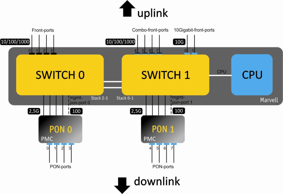
Figure 24 — Set of terminal interfaces
Table 19 shows types of terminal switch interfaces.
Table 19 — Interfaces types and numbers
Interface | Note | Quantity | Range |
|---|---|---|---|
10G-front-port | 2 | [0..1] | |
front-port | for LTP-4X | 4 | [0..3] |
for LTP-8X | 8 | [0..7] | |
pon-port | for LTP-4X | 4 | [0..3] |
for LTP-8X | 8 | [0..7] |
Ethernet interface configuration
Step 1. Switch to the view of the interface (of interface group), which settings should be changed.
LTP-8X# switch
LTP-8X(switch)# configure terminal
LTP-8X(switch)(config)# interface front-port 0
LTP-8X(switch)(config-if)#
Step 2. Enable the interface by using the no shutdown command. On the contrary, the shutdown command disables the interface.
LTP-8X(switch)(config-if)# no shutdown
Step 3. Enable or disable flow control (IEEE 802.3x PAUSE) by using the flow-control command.
LTP-8X(switch)(config-if)# flow-control on
Step 4. Enable or disable incoming packets filtering by using the ingress-filtering command. Only the packets of the VLANs, which have this interface, will pass the enabled filter. Other packets will be filtered out. If the filter is disabled, a packet will be processed regardless of its VID field.
LTP-8X(switch)(config-if)# ingress-filtering
Step 5. Specify a rule for VLAN tags processing for incoming packets by using the frame-types command. As a parameter, specify the packets to be allowed: either tagged (tagged only) or all (both tagged and untagged).
LTP-8X(switch)(config-if)# frame-types tagged
Step 6. Specify the port pvid, i. e. the VLAN, which will accommodate untagged packets. Specify the pup value, which is the priority of untagged packets.
LTP-8X(switch)(config-if)# pvid 100
LTP-8X(switch)(config-if)# pup 0
Step 7. If necessary, enable or disable packets transfer from this interface to another one (or a range of interfaces) by using the bridging to command. Pass interface type and number (or a range) as parameters. The interface types and numbers are given in Table 19.
All front-port interfaces are isolated by default, however data can be sent to any pon-port interface. The same is applicable to pon-port interfaces, which are isolated from each other, but can send data to any front-port interfaces.
LTP-8X(switch)(config-if)# bridging to front-port 1
Step 8. If needed, use the spanning-tree command group to adjust the STP protocol.
LTP-8X(switch)(config-if)# spanning-tree enable
LTP-8X(switch)(config-if)# spanning-tree priority 32
LTP-8X(switch)(config-if)# spanning-tree pathcost 0
LTP-8X(switch)(config-if)# spanning-tree admin-p2p auto
LTP-8X(switch)(config-if)# spanning-tree admin-edge
Step 9. If needed, set band limits for Broadcast, Multicast, Unknown Unicast and the whole traffic by using the rate-limit bc/mc/uu, and shaper commands correspondingly. As parameters, pass the maximum band width in kbps and the maximum length of uninterrupted transmission of packet batches in bytes.
LTP-8X(switch)(config-if)# rate-limit bc 1000 2048
LTP-8X(switch)(config-if)# rate-limit mc 1000 2048
LTP-8X(switch)(config-if)# shaper 100000 4000
Step 10. Set automatic determination of speed and duplex of the interface either by using the speed auto command or manually.
LTP-8X(switch)(config-if)# speed auto
Step 11. Set the interface description by the description command.
LTP-8X(switch)(config-if)# description org-uplink
Step 12. Enable mac notification trap if necessary. The device will send snmp-trap when learning new MAC or when deleting the old one.
LTP-8X(switch)(config-if)# snmp trap mac-notification added
LTP-8X(switch)(config-if)# snmp trap mac-notification removed
Step 13. Apply the configuration by using the commit command.
LTP-8X(switch)(config-if)# exit
LTP-8X(switch)(config)# commit
Configuring Storm Control
A storm appears due to excessive number of broadcast or/and multicast messages transmitted on the network via a single port simultaneously. It leads to an overload of the network resources and appearing of delays. A storm also can be caused by loopback segments of an Ethernet network. The switch evaluates the rate of incoming broadcast, multicast and unknown unicast traffic for port with enabled Storm Control and drops packets if the rate exceeds the set maximum value.
There is an opportunity to record a storm event to the log and disable the port for a specified time (in seconds).
LTP-8X(switch)(config-if)# rate-limit uu 1000 2048
LTP-8X(switch)(config-if)# rate-limit mc 1000 2048 logging
LTP-8X(switch)(config-if)# rate-limit bc 1000 2048 logging shutdown 30
For manual enabling of the port after blocking by Storm Control, use the clear storm command.
LTP-8X(switch)# clear storm front-port 0
GPON interface configuration
Step 1. Switch to the configure view.
LTP-8X# configure terminal
Step 2. Activate traffic encryption with the gpon olt encryption command if necessary. Specify the encryption key renewal period with the gpon olt encryption key-update command. Pass time period in seconds as a parameter.
LTP-8X(config)# gpon olt encryption
LTP-8X(config)# gpon olt encryption key-update 60
Step 3. Specify ONT authentication method with the gpon olt authentication command. ONTs can be authenticated by password, serial number, or both.
LTP-8X(config)# gpon olt authentication both
Step 4. Specify time of ONT blocking (in minutes) in case of MAC duplication or storm appearing. For details see the Configuring Storm Control section.
LTP-8X(config)# gpon olt ont-block-time 1
It is possible to receive a PON password of non-configured ONTs in an ALARM trap.
LTP-8X(config)# gpon olt password-in-trap
Step 5. Switch to GPON interface configuration.
LTP-8X(config)# interface gpon-port 0-7
Step 6. Enable or disable interfaces with the no shutdown or shutdown command respectively if necessary.
LTP-8X(config)(if-gpon-0-7)# no shutdown
Step 7. Activate FEC for interfaces with the fec command if necessary.
LTP-8X(config)(if-gpon-0-7)# fec
In case of using FEC, the real bandwidth decreases by ~10 %
Step 8. If necessary, enable the ability to migrate MAC addresses for selected interfaces.
LTP-8X(config)(if-gpon-0-7)# mac-migration
Step 9. Adjust time settings of optical transceivers if needed.
LTP-8X(config)(if-gpon-0-7)# optics use-custom
LTP-8X(config)(if-gpon-0-7)# optics ...
Optical transceivers should be adjusted only by agreement with Eltex Service Center.
Step 10. If necessary, enable unknown multicast with the following command.
LTP-8x(config)(if-gpon-7)# unknown-multicast-forward enable
Step 11. Apply the configuration by using the commit command.
LTP-8X(config)(if-gpon-0-7)# exit
LTP-8X(config)# do commit
GPON port force enable
LTP-X devices have the ability to forcibly enable GPON ports that are disabled in the configuration
LTP-8X# show interface gpon-port 7 state
    Reading:  .
    Gpon-port status information:
        Gpon-port:                             7
        State:                          DISABLED
        ONT count:                             0
        Force-mode:                     disabled
        ONT autofind:                    enabled
        SFP vendor:                       Ligent
        SFP product number:          LTE3680M-BC
        SFP vendor revision:                 1.0
        SFP temperature [C]:                  67
        SFP voltage [V]:                    3.28
        SFP tx bias current [mA]:            n/a
        SFP tx power [dBm]:                  n/a
To forcibly enable the port, put it into the force mode. The command is applied without entering the commit command.
LTP-8X# force-mode interface gpon-port 7
The command will not apply to an enabled gpon-port.
As a result, the port will be enabled until the next reconfiguration or reboot.
LTP-8X# show interface gpon-port 7 state
    Reading:  .
    Gpon-port status information:
        Gpon-port:                             7
        State:                                OK
        ONT count:                             0
        Force-mode:                      enabled
        ONT autofind:                    enabled
        SFP vendor:                       Ligent
        SFP product number:          LTE3680M-BC
        SFP vendor revision:                 1.0
        SFP temperature [C]:                  65
        SFP voltage [V]:                    3.25
        SFP tx bias current [mA]:          16.81
        SFP tx power [dBm]:                 3.34
The force-mode command stops if the device is reconfigured or rebooted, because it is not saved in the configuration.
Unknown-multicast traffic forwarding
LTP-X devices have the ability to forward unknown-multicast to broadcast-gem-port. Configuration is performed for each GPON port separately.
LTP-8X# configure terminal
LTP-8X(config)# interface gpon-port 0
LTP-8X(config)(if-gpon-0)# unknown-multicast-forward enable
LTP-8X(config)(if-gpon-0)# unknown-multicast-forward to broadcast-gem
This functionality is required for some protocols, such as IS-IS.
After applying the settings, the specified GPON port will be reconfigured, which will lead to the reconfiguration of all ONTs on the port.
GPON ports redundancy configuration
GPON port redundancy is designed to increase the reliability of the PON network. There are several types of redundancy: Type-A, Type-B, Type-C and Type-D. LTP-X supports Type-B redundancy. Type-B redundancy provides the ability to automatically switch between channels by using an additional GPON port. There are several ONT connection schemes (Figure 25 and Figure 26).
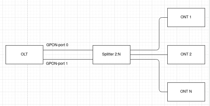
Figure 25 — Type-B redundancy. Connection scheme 1
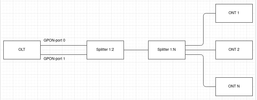
Figure 26 — Type-B redundancy. Connection scheme 2
Before beginning to operate with redundancy, make sure that OLT supports it.
Redundancy is supported on the following boards:
- LTP-4X/8X-rev.C with PLD version 14 and higher;
- LTP-4X/8X rev.D.
The necessary information can be obtained by using the show system environment command.
LTP-8X# show system environment
    System information:
        CPU load average (1m, 5m, 15m):   0.60  0.44  0.31
        Free RAM/Total RAM (Mbytes):      175/495
        Temperature (sensor1/sensor2):    40C/50C
        Reset button:                     enabled

        Fan configured speed, %:          auto
        Fan minimum speed, %:             15
        Fan speed levels, %:              16 27 39 51 64 76 88 100

        Fan state (fan0/fan1):            8640rpm  8760rpm

        PLD FW version:                   14

        TYPE:                             LTP-8X-rev.C
        HW_revision:                      1v4
        SN:                               GP2B000860
        MAC:                              E0:D9:E3:DF:E4:D0

        Power supply information:
                Module 1: PM160 220/12 1vX
                        Type: Alternate current(AC)
                        Intact: 1
                Module 2: PM150(75) 48/12 1vX
                        Type: Direct current(DC)
                        Intact: 0
Before connecting an ONT, check the list of supported ONTs (Table 20). For the proper redundancy operation, it is necessary to connect ONT to OLT according to one of the schemes (Figure 25 and Figure 26).
Table 20 — List of supported ONTs
Device | The version with which support began |
|---|---|
NTU-1(C) | 3.26.4 |
NTU-1 rev.B | 3.28.1 |
NTU-RG-5421G(С)-Wac | 1.2.1 |
NTU-RG-5421G-Wz | |
NTU-52V(C) | |
NTU-RG-5402G-W | |
NTU-RG-5440G-Wac | 2.1.0 |
NTU-RG-5440G-Wz |
Step 1. The redundancy configuration is performed with the gpon olt redundacy gpon-port command.
Redundancy can only be configured on 4 pairs of ports — 0-1, 2-3, 4-5 and 6-7, other combinations are not supported.
The gpon olt redundancy gpon-port command allows you to configure redundancy on one or more pairs at once.
LTP-8X# configure terminal
LTP-8X(config)# gpon olt redundancy gpon-port 0-1,2-3,4-5,6-7
LTP-8X(config)# do commit
Once configured, the even-numbered port defaults to the primary channel and the odd-numbered port to the redundant channel.
LTP-8X# show interface gpon-port 0-1 state
    Reading:  ..
    Gpon-ports status information:
        Gpon-port:                             0              1
        State:                                OK      REDUNDANT
        ONT count:                             0              0
        Force-mode:                     disabled       disabled
        ONT autofind:                    enabled        enabled
        SFP vendor:                       Ligent         Ligent
        SFP product number:          LTE3680M-BC    LTE3680M-BC
        SFP vendor revision:                 1.0            1.0
        SFP temperature [C]:                  70             39
        SFP voltage [V]:                    3.19           3.24
        SFP tx bias current [mA]:          17.29            n/a
        SFP tx power [dBm]:                 3.54            n/a
Step 2. Configure the ONT on an even-numbered port.
ONT configuration is performed only on even-numbered ports (0, 2, 4 and 6), odd-numbered ports use the configuration from even-numbered ports.
LTP-8X# configure terminal
LTP-8X(config)# interface ont 0/2
LTP-8X(config)(if-ont-0/2)# serial ELTX62108400
LTP-8X(config)(if-ont-0/2)# do commit
Once configured, the ONT will appear in the OK state on the main channel and in the REDUNDANT state on the redundant channel.
Step 3. To display ONT information on a pair of channels, use the show interface ont x-x redundant command.
LTP-8X# show interface gpon-port 0-1 state
    Reading:  ..
    Gpon-ports status information:
        Gpon-port:                             0              1
        State:                                OK      REDUNDANT
        ONT count:                             1              1
        Force-mode:                     disabled       disabled
        ONT autofind:                    enabled        enabled
        SFP vendor:                       Ligent         Ligent
        SFP product number:          LTE3680M-BC    LTE3680M-BC
        SFP vendor revision:                 1.0            1.0
        SFP temperature [C]:                  78             67
SFP voltage [V]: 3.18 3.23 SFP tx bias current [mA]: 18.94 n/a SFP tx power [dBm]: 3.54 n/a LTP-8X# show interface ont 0-1 redundant ----------------------------------- GPON-port 0 ONT redundant list ----------------------------------- ## Serial ONT ID GPON-port Status RSSI[dBm] Version EquipmentID 1 ELTX62108400 2 0 OK -10.71 3.28.1.69 NTU-1 ----------------------------------- GPON-port 1 ONT redundant list ----------------------------------- ## Serial ONT ID GPON-port Status RSSI[dBm] Version EquipmentID 1 ELTX62108400 2 1 REDUNDANT n/a 3.28.1.69 NTU-1 Total ONT count: 2
In case of malfunction on the main channel, such as line breakage, there will be a seamless channel change — the redundant channel will become the main channel, the main channel in this case will go to redundant state. Seamless channel change is the transition of all ONTs from the main channel to the redundant channel without interrupting client sessions.
LTP-8X# show interface ont 0-1 redundant

-----------------------------------
GPON-port 0 ONT redundant list
-----------------------------------

        ##         Serial   ONT ID   GPON-port      Status   RSSI[dBm]     Version   EquipmentID
         1   ELTX62108400        2           0   REDUNDANT         n/a   3.28.1.69         NTU-1

-----------------------------------
GPON-port 1 ONT redundant list
-----------------------------------

        ##         Serial   ONT ID   GPON-port   Status   RSSI[dBm]     Version   EquipmentID
         1   ELTX62108400        2           1       OK      -14.85   3.28.1.69         NTU-1

Total ONT count: 2
Once the communication line is restored, there will be no switching back. The next switch will only occur if there is a malfunction on the current main channel.
Port Mirroring configuration
Port mirroring is used to duplicate the traffic on monitored ports by sending ingress or and/or egress packets to the controlling port. Users can define a controlled port and controlling ports and select the type of the traffic (ingress or egress), which will be sent to the controlling port.
Configuration of the controlled port
Step 1. Mirroring is configured in the terminal switch. Execute the switch and configure commands consecutively to switch to the config view.
LTP-8X# switch
LTP-8X(switch)# configure terminal
LTP-8X(switch)(config)#
Step 2. Configure the pon-port mirroring for ingress and egress traffic.
LTP-8X(switch)(config)# mirror rx interface pon-port 0
LTP-8X(switch)(config)# mirror tx interface pon-port 0
Step 3. Apply the configuration by using the commit command.
LTP-8X(switch)(config)# commit
Configuration of the controlling port
Step 1. Switch to the switch config view by using the switch and configure commands.
LTP-8X# switch
LTP-8X(switch)# configure terminal
LTP-8X(switch)(config)#
Step 2. Configure mirroring and traffic analysis for any front-port.
LTP-8X(switch)(config)# mirror rx analyzer front-port 7
LTP-8X(switch)(config)# mirror tx analyzer front-port 7
Step 3. If necessary, add a VLAN tag to be used for all mirrored traffic and packet priority.
LTP-8X(switch)(config)# mirror add-tag
LTP-8X(switch)(config)# mirror rx added-tag-config vlan 1555 user-prio 0
LTP-8X(switch)(config)# mirror tx added-tag-config vlan 1555 user-prio 0
Step 4. Apply the configuration by using the commit command.
LTP-8X(switch)(config)# commit
LLDP configuration
Link Layer Discovery Protocol (LLDP) is a Data link layer protocol that allows network devices to announce information about themselves and their capabilities to the network, as well as to collect this information about neighboring devices. The standard RFC mib 1.0.8802 are supported by the SNMP agent.
LLDP configuration
Step 1. Activate the LLDP.
LTP-8X(switch)(config)# lldp enable
Step 2. If necessary, configure LLDPDU transfer mode.
LTP-8X(switch)(config)# interface front-port 0
LTP-8X(switch)(config-if)# lldp mode transmit-receive
Step 3. Configure optional LLDP-TLVs for ports.
LTP-8X(switch)(config-if)# lldp optional-tlv sys-desc
LTP-8X(switch)(config-if)# lldp optional-tlv port-desc
Step 4. Specify the amount of time for the receiver to keep LLDP packets before dropping them.
LTP-8X(switch)(config)# lldp hold-multiplier 5
This value will be transmitted to the receiving side in the LLDP update packets; and should be an increment for the LLDP timer. Thus, the lifetime of LLDP packets is calculated by the formula.
TTL = min(65535,LLDP-Timer * LLDP-HoldMultiplier)
Step 5. Set the reinitialization time of LLDP.
LTP-8X(switch)(config)# lldp reinit 3
Step 6. Specify how often the device will send LLDP information updates.
LTP-8X(switch)(config)# lldp timer 60
Step 7. Specify the delay between the subsequent LLDP packet transmissions caused by the changes of values or status in the local LLDP MIB database.
LTP-8X(switch)(config)# lldp tx-delay 3
It is recommended that this delay be less than 0.25* LLDP-Timer.
Step 8. Specify the processing mode of LLDP packets.
LLDP packet processing mode:- filtering — LLDP packets are filtered if LLDP is disabled on the switch;
- flooding — LLDP packets are transmitted if LLDP is disabled on the switch.
LTP-8X(switch)(config)# lldp lldpdu flooding
- Step 9. Apply the configuration by using the commit command.
LTP-8X(switch)(config)# commit
ERPS configuration
ERPS (Ethernet Ring Protection Switсhing) — link layer protocol designed to increase the stability and reliability of a data network by creating a ring topology with logical blocking of interfaces. It is realized by reducing recovery network time in case of breakdown. Recovery time does not exceed 1 second. It is much less than network change over time in case of spanning tree protocols usage.
ERPS configuration
Step 1. Enable ERPS.
LTP-8X(switch)(config)# erps enable
Step 2. Create an ERPS ring with the R-APS VLAN identifier through which service traffic will be transmitted.
LTP-8X(switch)(config)# erps vlan 700
Step 3. Specify east/west port.
LTP-8X(switch)(config-erps)# port east front-port 3
LTP-8X(switch)(config-erps)# port west port-channel 1
Step 4. Set the range of secure VLANs.
LTP-8X(switch)(config-erps)# protected vlan add 100-103
Step 5. If necessary, assign the RPL port with the owner/neighbor command.
LTP-8X(switch)(config-erps)# rpl east owner
Step 6. Change the timers if necessary.
LTP-8X(switch)(config-erps)# timer guard 10
LTP-8X(switch)(config-erps)# timer holdoff 100
LTP-8X(switch)(config-erps)# timer wtr 1
Step 7. Specify a subring if necessary.
LTP-8X(switch)(config-erps)# sub-ring vlan 750
Step 8. Enable the ring by the enable command.
LTP-8X(switch)(config-erps)# ring enable
Step 9. View the status of the generated ERPS ring.
LTP-8X(switch)# show erps vlan 700
R-APS VLAN : 700
Admin Status : Enabled
West Port : port-channel 1 (Signal Fail)
East Port : front-port 1 (Forwarding)
RPL Port : East
RPL Owner : Enabled (Active)
Protected VLANs : 100-103
Ring MEL : 1
Holdoff Time : 100 msec
Guard Time : 10 msec
WTR Time : 1 min
Current Ring State : Protection
Revertive : Yes
Compatibility with version : 2

Sub-Ring R-APS VLAN   TC Propagation State
-------------------   --------------------
750                   Disable
ARP-Inspection configuration
The ARP Inspection function is dedicated to defense against attacks which use ARP (for instance, ARP-spoofing — ARP traffic interception). ARP Inspection is implemented on the basis of static correspondence between IP and MAC addresses defined for VLAN.
ARP-Inspection configuration
Step 1. Switch to the switch config view by using the switch and configure commands.
LTP-8X# switch
LTP-8X(switch)# configure terminal
LTP-8X(switch)(config)#
Step 2. Enable arp inspection, add static entries.
LTP-8X(switch)(config)# ip arp inspection
LTP-8X(switch)(config)# ip arp inspection static-table 1.1.1.1 A8:F9:4B:11:11:01
LTP-8X(switch)(config)# ip arp inspection static-table 1.1.1.2 A8:F9:4B:11:11:10 vlan 10
Step 3. Configure trusted and untrusted interfaces.
LTP-8X(switch)(config)# interface front-port 7
LTP-8X(switch)(config-if)# no ip arp inspection trusted
LTP-8X(switch)(config)# interface front-port 0 — 6
LTP-8X(switch)(config-if)# ip arp inspection trusted
Step 4. Apply the configuration by using the commit command.
LTP-8X(switch)(config)# commit
QoS rules configuration
The traffic prioritization and allocation by hardware queues (IEEE 802.1p/DSCP) are implemented on the basis of set rules in the system.
Table 21 — Traffic prioritization methods
Method | Description |
|---|---|
0 | All the priorities are equal |
1 | Packet selection according to IEEE 802.1p |
2 | Packet selection only according to IP ToS (Type of Service) on 3 level — support for Differentiated Services Codepoint (DSCP) |
3 | Interaction according to either 802.1p or DSCP/TOS |
Step 1. Set a queue on which packets will be transmitted without preset rules. The 0 queue has the least priority.
LTP-8X(switch)(config)# qos default 0
Step 2. Set a traffic prioritization method by using the qos type command. Send a type of prioritization as an argument.
LTP-8X(switch)(config)# qos type 1
Step 3. Using qos map command, set rules for translation of 802.1p and DSCP/TOS to a queue number. Send field type and priorities lists as parameters.
LTP-8X(switch)(config)# qos map 1 0-4,15,63 to 6
LTP-8X(switch)(config)# commit
LTP-8X(switch)(config)# exit
LTP-8X(switch)# show qos
Priority assignment by 802.1p packet field
Default priority queue is 0
DSCP queues:
7: 63
6:
5:
4:
3:
2:
1:
0:
802.1p queues:
7: 7
6: 6
5: 5
4: 4
3: 3
2: 2
1: 1
0: 0
WRR queues disabled
WRR values for queues 7..0: 8 7 6 5 4 3 2 1
Weighted Round Robin (WRR) configuration
Weighted Round Robin (WRR) — an algorithm which distribute throughput by classes, using a scheme of weighted round robin. The OLT has 8 hardware queues.
Step 1. Enable WRR and set 4 queues (0, 1, 2, 3) which will be processed by the algorithm. The other queues will be strict. The WRR queues are enumerated from 0.
LTP-8X(switch)(config)# qos wrr enable 4
Step 2. The weight of each queue, starting with the 7th.
LTP-8X(switch)(config)# qos wrr queues 1 1 1 1 60 20 15 5
Step 3. Save the configuration.
LTP-8X(switch)(config)# commit
LTP-8X(switch)(config)# exit
LTP-8X(switch)# exit
LTP-8X# save
LAG configuration
This chapter describes configuration of uplink interfaces aggregation. Link aggregation (IEEE 802.3ad) is a technology that allows multiple physical links to be combined into one logical link (aggregation group). Aggregation group has a higher throughput and is very reliable.

Figure 27 — Multiple physical links combined to an aggregation group
The terminal supports two interface aggregation modes: static and dynamic. Static aggregation implies that all communication links of a group are always active. As for dynamic aggregation, link activity is dynamically determined during operation via LACP protocol.
Table 22 — Operation modes of aggregation groups
Mode | Description |
|---|---|
static | Link aggregation protocol is not used |
lacp | LACP is used |
The terminal has several algorithms of load balancing within aggregation groups.
Table 23 — Load balancing modes
Mode | Description |
|---|---|
ip | Based on IP addresses of sender and receiver |
ip-l4 | Based on IP addresses of sender and receiver, and L4 |
mac | Based on MAC addresses of sender and receiver |
mac-ip | Based on MAC and IP addresses of sender and receiver |
mac-ip-l4 | Based on MAC and IP addresses and L4 of sender and receiver |
The terminal supports two LACP modes. Passive — the terminal does not initiate creation of a logical link, but processes incoming LACP packets. Active — the terminal creates an aggregated communication link and initiates parameters conformance. The parameters are coordinated if equipment operates in active or passive LACP modes.
LAG configuration
LAG configuration represents configuration of static aggregation and LACP. To configure LAG, perform the steps marked blue in Figure 28. LACP configuration requires all steps to be performed.
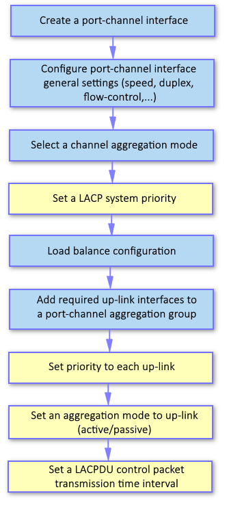
Figure 28 — LAG and LACP configuration procedure
Step 1. LAG is configured in the terminal switch. Execute the switch and configure commands consecutively to switch to the config view.
LTP-8X# switch
LTP-8X(switch)# configure terminal
LTP-8X(switch)(config)#
Step 2. Create a port-channel logical interface by using the interface port-channel command.
As a parameter, pass the number of the interface being created. Up to ten logical interfaces can be created.
LTP-8X(switch)(config)# interface port-channel 3
LTP-8X(switch)(config-if)#
- Step 3. Set general interface parameters: speed, duplex, flow-control, etc. Interfaces configuration is described in detail in the Interface configuration section.
Step 4. Configure aggregation by using the mode command. Pass the operation mode as a parameter. Operation modes are specified in Table 22.
LTP-8X(switch)(config-if)# mode lacp
Step 5. This step should only be performed for LACP configuration. Set a LACP system priority by using the lacp system-priority command. The no lacp system-priority command returns 32768 (default value).
LTP-8X(switch)(config-if)# exit
LTP-8X(switch)(config)# lacp system-priority 32541
The lacp system-priority command can be executed in the configure view of the terminal switch.
Step 6. Specify load balancing rules by using the port-channel load-balance command if needed. Pass the load balancing mode as a parameter. Balance modes are specified in Table 23.
LTP-8X(switch)(config)# port-channel load-balance ip
The port-channel load-balance command can be executed in the configure view of the terminal switch.
Step 7. When used for load balancing, L4 parameters require a long hash. Enable the long hash by using the port-channel l4-long-hash enable command.
LTP-8X(switch)(config)# port-channel l4-long-hash enable
The port-channel l4-long-hash command can be executed in the configure view of the terminal switch.
Step 8. Add physical interfaces into the logical one by using the channel-group command. As a parameter, pass the number of the logical interface.
LTP-8X(switch)(config)# interface front-port 0 — 4
LTP-8X(switch)(config-if-range)# channel-group port-channel 3
The channel-group command can be executed in the configure view of an interface (a range) of the switch.
Step 9. This step should only be performed for LACP configuration. Set a priority for a physical interface by using the lacp port-priority command if necessary. The no lacp port-priority command resets port priority to the default value of 32768; 1 is the highest priority.
LTP-8X(switch)(config-if-range)# no lacp port-priority
LTP-8X(switch)(config-if-range)# exit
LTP-8X(switch)(config)# interface front-port 0
LTP-8X(switch)(config-if)# lacp port-priority 256
The lacp port-priority command can be executed in the configure view of a switch interface.
Step 10. This step should only be performed for LACP configuration. Use the lacp mode command to set an active or passive LACP mode.
LTP-8X(switch)(config-if)# exit
LTP-8X(switch)(config)# interface port-channel 3
LTP-8X(switch)(config-if)# lacp mode active
Step 11. This step should only be performed for LACP configuration. In case of the active LACP mode, set an interval for transmission of LACP control packets by using the lacp rate command. Pass slow (30 seconds) or fast (1 second) as a parameter.
LTP-8X(switch)(config-if)# lacp rate slow
Step 12. Apply the configuration by using the commit command.
LTP-8X(switch)(config-if)# exit
LTP-8X(switch)(config)# commit
DHCP Relay Agent configuration
This chapter describes configuration of DHCP Relay Agent in the terminal.
DHCP Relay Agent is used to provide a DHCP server with additional information about a received DHCP request. This may include information about the terminal running DHCP Relay Agent as well as information about the ONT, which sent the DHCP request. DHCP packets are modified by interception and further processing in the terminal CPU.
The DHCP server analyses DHCP option 82 and identifies the ONT. DHCP Relay Agent allows the option to be both transparently transmitted from the ONT and formed/rewritten according to a specified format. DHCP option 82 is especially useful for networks, which have no private VLANs dedicated for each user.
DHCP Relay Agent supports configurable formats for both Circuit ID and Remote ID. The format of the suboptions is configured with the help of the tokens listed in Table 24. The placeholders will be replaced with corresponding values, while the rest of the words will be passed as is.
Table 24 — DHCP Option 82 tokens
Token | Description |
|---|---|
%HOSTNAME% | Terminal network name |
%MNGIP% | Terminal IP address |
%GPON-PORT% | Number of the OLT channel the DHCP request arrived from |
%ONTID% | ID of the ONT, which sent the DHCP request |
%PONSERIAL% | Serial number of the ONT, which sent the DHCP request |
%GEMID% | ID of the GEM port the DHCP request arrived to |
%VLAN0% | External VID |
%VLAN1% | Internal VID |
%MAC% | MAC address of the ONT, which sent the request |
%OLTMAC% | OLT MAC address |
%OPT60% | DHCP option 60 received from the ONT |
%OPT82_CID% | Circuit ID received from the ONT |
%OPT82_RID% | Remote ID received from the ONT |
%DESCR% | First 20 characters of ONT description |
In addition to DHCP option 82, DHCP Relay Agent has some more functions related to network security. It provides protection from DoS attacks by setting a threshold for intensity of DHCP messages, which are received from ONT. Exceeding the threshold blocks DHCP requests. The blocking time can be configured.
It also protects from illegal DHCP servers by controlling the source IP address of DHCP responses. Transmitted are only the DHCP responses, which arrived from IP addresses of trusted DHCP servers.
DHCP Relay Agent profiles management
A set of profiles is used for DHCP Relay Agent configuration. All VLANs use dhcp-ra-00 profile by default.
The configuration is flexible as it allows DHCP profiles to be assigned not only to a terminal on the whole, but separately to each VLAN as well. To assign a profile, the following steps should be taken.
Step 1. Assign the default profile for all VLANs with the help of the gpon olt profile dhcp-ra dhcp-ra-00 command.
LTP-8X# configure terminal
LTP-8X(config)# gpon olt profile dhcp-ra dhcp-ra-00
Step 2. Create a new DHCP Relay Agent profile with the help of the profile dhcp-ra command if necessary. Pass profile name as a parameter.
LTP-8X(config)# profile dhcp-ra dhcp-ra-01
LTP-8X(config-dhcp-ra)("dhcp-ra-01")# exit
Step 3. Assign the newly created profile to a selected VLAN with the gpon olt profile dhcp-ra dhcp-ra-01 command. As a parameter, pass the VID, which requires individual configuration.
LTP-8X(config)# gpon olt profile dhcp-ra dhcp-ra-01 vid 1000
Step 4. Check the changes by using the show gpon olt configuration command.
LTP-8X(config)# do show gpon olt configuration
		Profile dhcp-ra:		dhcp-ra-00		OLT Profile DHCP Relay Agent 0
Profile dhcp-ra per VLAN 1000 [0]:
			Profile:			dhcp-ra-01		OLT Profile DHCP Relay Agent 1
Step 5. Apply the changes by using the commit command.
LTP-8X(config)# do commit
To apply the changes, the OLT should be reconfigured.
DHCP Relay Agent profiles configuration
Step 1. Switch to the corresponding DHCP Relay Agent profile.
LTP-8X(config)# profile dhcp-ra dhcp-ra-01
Step 2. Enable DHCP traffic processing with the enable command.
LTP-8X(config-dhcp-ra)("dhcp-ra-01")# enableStep 3. Enable insert/overwrite of DHCP option 82 with the help of the overwrite-option82 command if needed.
LTP-8X(config-dhcp-ra)("dhcp-ra-01")# overwrite-option82Step 4. Specify the DHCP option 82 format with the help of the overwrite-option82 circuit-id and overwrite-option82 remote-id commands if needed. A list of possible tokens is given in Table 24.
LTP-8X(config-dhcp-ra)("dhcp-ra-01")# overwrite-option82 circuit-id "%HOSTNAME% %MAC% %OPT82_CID%"
LTP-8X(config-dhcp-ra)("dhcp-ra-01")# overwrite-option82 remote-id "%OPT82_RID%"
Step 5. Enable DoS attack protection with the help of the dos-block command if needed. Specify a threshold for the number of DHCP queries per second that will block queries when exceeded. Use the dos-block packet-limit command for it. Use the dos-block block-time command to specify the blocking time in seconds.
LTP-8X(config-dhcp-ra)("dhcp-ra-01")# dos-block
LTP-8X(config-dhcp-ra)("dhcp-ra-01")# dos-block packet-limit 200
LTP-8X(config-dhcp-ra)("dhcp-ra-01")# dos-block block-time 300
Step 6. Set a list of trusted DHCP servers with the help of the trusted primary and trusted secondary commands. Specify a response timeout for DHCP servers by using the trusted timeout command. Activate filters with the help of the trusted command.
LTP-8X(config-dhcp-ra)("dhcp-ra-01")# trusted primary 10.0.0.1
LTP-8X(config-dhcp-ra)("dhcp-ra-01")# trusted secondary 10.0.0.2
LTP-8X(config-dhcp-ra)("dhcp-ra-01")# trusted timeout 100
LTP-8X(config-dhcp-ra)("dhcp-ra-01")# trusted
Step 7. Apply the changes by using the commit command.
LTP-8X(config-dhcp-ra)("dhcp-ra-01")# do commitTo apply the changes, the OLT should be reconfigured.
Active DHCP leases monitoring
When enabled, DHCP-RA allows monitoring of DHCP leases. To view the list of sessions, use the do show interface gpon-port 0 dhcp sessions command.
LTP-4X# show interface gpon-port 1 dhcp sessions
    DHCP sessions (2):
##      Serial       ONT  Service       IP                 MAC          Vid    GEM  Life time
1  454C5458690000E8  1/4    1     192.168.101.102  A8:F9:4B:E5:67:8B    1101   433   3587
2  454C5458690000E8  1/4    0     192.168.200.51   A8:F9:4B:E5:67:8A    600    432   86307
It is also possible to remove dynamic entries from the DHCP snooping table with the clear dhcp-sessions interface ont command.
LTP-8X# clear dhcp-sessions interface ont <0-7>[/0-127]
Broadcast-unicast relay configuration
To reduce the broadcast traffic and avoid responses from illegal DHCP-servers, unicast messages can be configured to interact with the specified DHCP Relay Agent. Relay Agent can be individually started for each separate VLAN. The service allows processing only for the packets, which have only one 802.1q tag.
Step 1. Create an L3 interface by specifying the IP address of the VLAN the service is provided for. If the address of the DHCP server is in the same network as the management interface, skip Step 3. If the DHCP server is in the VLAN, which is specified in cross-connect, the IP address of the interface being created should be in the same network as the DHCP server, and you should skip Step 3.
LTP-8X(switch)(config)# vlan 2000
LTP-8X(switch)(config-vlan)# ip address 10.10.10.1/32
Step 2. Specify up to 3 addresses of DHCP servers.
LTP-8X(switch)(config-vlan)# ip dhcp relay 192.168.56.1
LTP-8X(switch)(config-vlan)# ip dhcp relay 192.168.56.2
Step 3. Create an L3 interface by specifying the IP address of the VLAN, which is used for switching in the network where the DHCP server is located.
LTP-8X(switch)(config)# vlan 1209
LTP-8X(switch)(config-vlan)# ip address 192.168.209.240/24
Step 4. If the addresses of the DHCP servers are located after the router available after the specified L3 interface, configure a static route.
LTP-8X# configure terminal
LTP-8X(config)# ip route prefix 192.168.56.0 mask 24 gateway 192.168.209.5
LTP-8X(config)# do commit
Step 5. If VLAN in which interception of DHCP requests is implemented is the same as management VLAN of OLT (e.g. OLT connects to only one VLAN or traffic untagged), you need to explicitly enable redirection of DHCP requests on the VLAN.
LTP-8X(switch)(config)# vlan 1209
LTP-8X(switch)(config-vlan)# ip dhcp relaying
PPPoE Intermediate Agent configuration
This chapter describes configuration of PPPoE Intermediate Agent of the terminal.
PPPoE Intermediate Agent is used to provide BRAS with additional information about a received PADI request. This may include information about the terminal running PPPoE Intermediate Agent as well as information about the ONT, which sent the PADI request. PADI packets are modified by interception and further processing in the terminal CPU.
BRAS analyses the Vendor Specific tag and identifies the ONT. PPPoE Intermediate Agent forms or rewrites the Vendor Specific tag using a specified format. Vendor Specific tags are especially useful for networks, which have no private VLANs dedicated for each user.
PPPoE Intermediate Agent supports configurable formats for Circuit ID and Remote ID. The format of the suboptions is configured with the help of the tokens listed in Table 25. The placeholders will be replaced with corresponding values, while the rest of the words will be passed as is.
Table 25 — Vendor Specific tag tokens
Token | Description |
|---|---|
%HOSTNAME% | Terminal network name |
%MNGIP% | Terminal IP address |
%GPON-PORT% | Number of the OLT channel the PADI request arrived |
%ONTID% | ID of the ONT, which sent the PADI request |
%PONSERIAL% | Serial number of the ONT, which sent the PADI |
%GEMID% | ID of the GEM port the PADI request arrived to |
%VLAN0% | External VID |
%VLAN1% | Internal VID |
%MAC% | MAC address of the ONT, which sent the request |
%OLTMAC% | OLT`s MAC address |
%DESCR% | First 20 characters of ONT description |
In addition to vendor specific tag support, PPPoE Intermediate Agent has some more functions related to network security. It provides protection from DoS attacks by setting a threshold for intensity of PADI messages, which are received from ONT. Exceeding the threshold blocks PADI requests. The blocking time can be configured.
PPPoE Intermediate Agent also limits the number of simultaneous PPPoE sessions. The restriction can be set for both the total number of terminal sessions and for every ONT separately.
PPPoE Intermediate Agent profile configuration
To configure a PPPoE Intermediate Agent profile, the following steps should be taken.
Step 1. Switch to the PPPoE Intermediate Agent profile.
LTP-8X# configure terminal
LTP-8X(config)# profile pppoe-ia pppoe-ia-00
LTP-8X(config-pppoe-ia)("pppoe-ia-00")#
Step 2. Enable PPPoE traffic processing with the enable command.
LTP-8X(config-pppoe-ia)("pppoe-ia-00")# enableStep 3. Specify the vendor specific tag format with the help of the format circuit-id and format remote-id commands. A list of possible tokens is given in Table 25.
LTP-8X(config-pppoe-ia)("pppoe-ia-00")# format circuit-id "%HOSTNAME%"
LTP-8X(config-pppoe-ia)("pppoe-ia-00")# format remote-id "%PONSERIAL%:%GEMID%"
Step 4. Enable DoS attack protection with the help of the dos-block command if needed. Specify a threshold for the number of DHCP queries per second that will block queries when exceeded. Use the dos-block packet-limit command for it. Use the dos-block block-time command to specify the blocking time in seconds.
LTP-8X(config-pppoe-ia)("pppoe-ia-00")# dos-block
LTP-8X(config-pppoe-ia)("pppoe-ia-00")# dos-block packet-limit 200
LTP-8X(config-pppoe-ia)("pppoe-ia-00")# dos-block block-time 300
Step 5. Set the limits of PPPoE sessions by using the sessions-limit command.
LTP-8X(config-pppoe-ia)("pppoe-ia-00")# sessions-limit 128 per-user 2If there is no need to limit sessions for all ONTs, pass unlimited parameter in session-limit per-user command.
LTP-8X(config-pppoe-ia)("pppoe-ia-00")# sessions-limit per-user unlimitedIf you need to disable limiting session for specified ONT (might be useful for SFP-ONU) and save limiting for others, define limiting globally in the profile and disable it in the interface ont settings.
LTP-8X(config-pppoe-ia)("pppoe-ia-00")# sessions-limit 8192 per-user 2
LTP-8X(config-pppoe-ia)("pppoe-ia-00")# exit
LTP-8X(config)# interface ont 0/0
LTP-8X(config)(if-ont-0/0)# pppoe-sessions-unlimit
Step 6. Apply the changes by using the commit command.
LTP-8X(config-pppoe-ia)("pppoe-ia-00")# do commitTo apply the changes, the OLT should be reconfigured.
Active PPPoE sessions monitoring
Enabling PPPoE-IA allows active PPPoE sessions to be monitored. To view the list of sessions, use the following command.
LTP-8X(config)(if-ont-0/4)# do show interface gpon-port 0 pppoe session
PPPoE sessions (1):
 ## Serial            GPON-port Ont ID  Port  Client             Session ID   Duration    Unblock
 1  454C54586700008C  0         4        353   A8:F9:4B:E3:16:5C  0x0003       0:00:27     0:00:00
Disabling session monitoring
The session monitoring is enabled in PPPoE-IA by default. Due to the fact that system resources are used for each session, in this mode, there are 8192 sessions to be initialized through the OLT (the maximum session-limit value).
If you need to bypass this limit and save opportunity to fill the Vendor-Specific tag fields, you can disable the monitoring. Use the following command.
LTP-8X(config-pppoe-ia)("pppoe-ia-00")# no sessions-monitoring enable
LTP-8X(config-pppoe-ia)("pppoe-ia-00")# do commit
To enable the monitoring, use the command:
LTP-8X(config-pppoe-ia)("pppoe-ia-00")# sessions-monitoring enable
LTP-8X(config-pppoe-ia)("pppoe-ia-00")# do commit
PPPoE-IA is capable to detect sessions which are established while session monitoring is enabled. If a session was established before monitoring being enabled, re-initiate the session.
IP Source Guard configuration
The IP Source Guard function allows restriction of unauthorised usage of IP addresses in the network by linking IP and MAC addresses of the source to a specific service on a specific ONT. There are two operation modes:
- To enable transmission of any traffic from clients, it is necessary to specify an explicit match between MAC and IP addresses of client equipment.
- Client equipment obtains its address via the DHCP protocol. Based on data exchange between client equipment and the DHCP server, a DCHP snooping table is generated on the OLT that contains MAC-IP-GEM port matches and information about lease period. Only the packets with source MAC and source IP fields matching the records in the DHCP snooping table are passed from the client. To support client equipment with static IP addresses, static entries can be created in the dynamic mode.
To enable the IP Source Guard functions, enable DHCP-RA. For more information on DHCP-RA, see DHCP Relay Agent configuration.
These functions are not supported in Model 1 (for more information about models, see Service Models).
When IP Source Guard is enabled, any non-IP traffic is forbidden.
IP Source Guard configuration
Step 1. Switch to the configure view.
LTP-8X# configure terminal
Step 2. Enable IP Source Guard and specify the mode.
LTP-8X(config)# ip source-guard enable
LTP-8X(config)# ip source-guard mode dynamic
Step 3. Apply the changes by using the do commit command.
LTP-8X(config)# do commit
After the IPSG mode has been enabled/disabled/changed, the OLT is reconfigured automatically.
To enable DHCP session reset for a device with the same MAC address, there is an option:
LTP-8X(config)# ip source-guard one-dynamic-binding-for-MAC
It will automatically overwrite the old session with the new one.
To add static matches, use the following command:
LTP-8X(config)# ip source-guard bind ip <IP> mac <MAC> interface-ont <ONT> service <NUM>
Where:
- IP — IP address of client equipment in X.X.X.X format;
- МАС — MAC address of client equipment in ХХ:XX:XX:XX:XX:XX format;
- ONT — ONT identifier in SLOT_ID/CNANNEL_ID/ONT_ID format;
- NUM — ONT service number, through which traffic with specific addresses will be transmitted, from 0 to 7.
To disable IP Source Guard and remove static matches, use the negative no command.
LTP-8X(config)# no ip source-guard enable
LTP-4X(config)# no ip source-guard bind ip <IP>
In case of OLT power supply loss, entries of DHCP snooping table might be lost. In this case the service will not work until the address is prolonged or received again. The problem usually occurs when lease time is long. You may solve the problem by saving of snooping table in non-volatile memory:
Step 1. Configure saving of IP Source Guard entries by timer.
LTP-8X(config)# ip source-guard database enable
LTP-8X(config)# ip source-guard database update-freq 1020
Step 2. If necessary, disable IP Source-Guard in the specified VLAN.
LTP-8X(config)# ip source-guard ignore-vlan 10
LTP-8X(config)# ip source-guard ignore-vlan 20
LTP-8X(config)# ip source-guard mode dynamic
Step 3. Apply changes by the do commit command.
LTP-8X(config)# do commit
Step 4. To view information about the status, mode, and static matches, use the show command.
LTP-8X# show ip source-guard
    IP Source Guard:
        Enabled:                                       true
        Mode:                                          dynamic
        Database enabled:                              true
        Database update frequency:                     1020
        Bind [0]:
            Ip:                                        192.168.200.90
            Mac:                                       00:22:B0:50:59:71
            Interface-ont:                             0/4
            Service:                                   2
        Vlan [10]                                      Allowed
        Vlan [20]                                      Allowed
IP Source Guard Database will work only if automatic time synchronization is implemented via NTP.
Configuring multicast traffic between ONTs within the same tree
The functionality allows you to turn multicast traffic to the same port from which it been received. The configuration consists of two parts: vlan configuration, multicast in which pon-port should be deployed, and on which the functional will operate.
Configuration:
Step 1. Switch to the view of vlan whose settings you want to change.
LTP-8X# switch
LTP-8X(switch)# configure terminal
LTP-8X(switch)(config)# vlan 400
LTP-8X(switch)(config-vlan)#
Step 2. Enable multicast loopback.
LTP-8X(switch)(config-vlan)# multicast loopback enable
Step 3. Return to the config view and switch to the view interface whose settings you want to change.
LTP-8X(switch)(config-vlan)# exit
LTP-8X(switch)(config)# interface pon-port 4
Step 4. Enable multicast loopback and apply the changes.
LTP-8X(switch)(config-if)# multicast loopback enable
LTP-8X(switch)(config-if)# commit
ONT configuration
Service Models
This chapter considers main terms and classification of service models.
In general, a service model is based on a method which describes how the services are provided: «VLAN for Subscriber» or «VLAN for Service». The VLAN for Service architecture means that a service VLAN (S-VLAN) is used to provide all users with a certain service. The VLAN for Subscriber architecture implies that a client VLAN (C-VLAN) is used to provide a user with multiple services. These methods are often combined in practice and form a hybrid model, which uses S-VLAN and C-VLAN simultaneously.
VLAN for Subscriber architecture
A separate VLAN is used for each subscriber in the C-VLAN model. A dedicated C-VLAN is used to provide services to each user between the OLT and service routers. Service GEM ports are created for every OLT service between every ONT and the OLT. When a service request is generated upstream, records are added to the MAC table in the OLT according to C-VLAN. In case of downstream traffic, a corresponding GEM port is determined for a definite service according to the MAC table in the OLT.
If the destination address of the downstream transmission is unknown (broadcast or unknown unicast), i. e. the GEM port cannot be determined, two options are available:
- transmission through a dedicated broadcast GEM port;
- transmission to all GEM ports, which correspond to the services provided to the subscriber.
The destination address, in case it is unknown (broadcast or unknown unicast), will be determined based on the method implemented in a definite service model.
The architecture of this service model is shown in figure below.
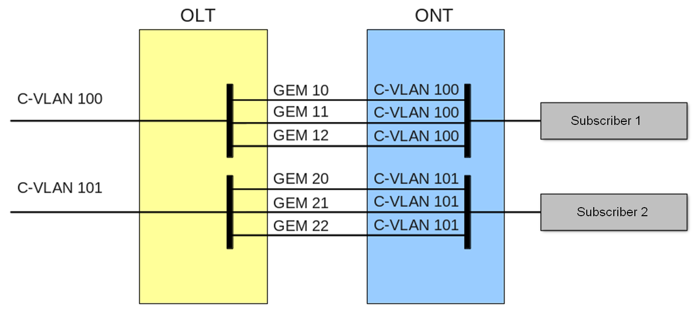
Figure 29 — "VLAN for Subscriber" service model architecture
VLAN for Service architecture
The S-VLAN model has a separate VLAN for every service. Consider its operation on an example of an abstract S-VLAN 100 service.
S-VLAN 100 is used between the OLT and service routers that is global for all subscribers in terms of this service. When a service request is generated upstream, records are added to the MAC table in the OLT according to S-VLAN and subscriber's MAC address. In case of downstream traffic, a corresponding subscriber of the service is determined based on the MAC table.
If the destination address of the downstream transmission is unknown (broadcast or unknown unicast), i. e. the GEM port cannot be determined, two options are available:
- transmission through a dedicated broadcast GEM port (traffic is transmitted to all subscribers);
- transmission to every subscriber through a GEM port corresponding to the service.
The destination address, in case it is unknown (broadcast or unknown unicast), will be determined based on the method implemented in a definite service model.
The architecture of this service model is shown in figure below.
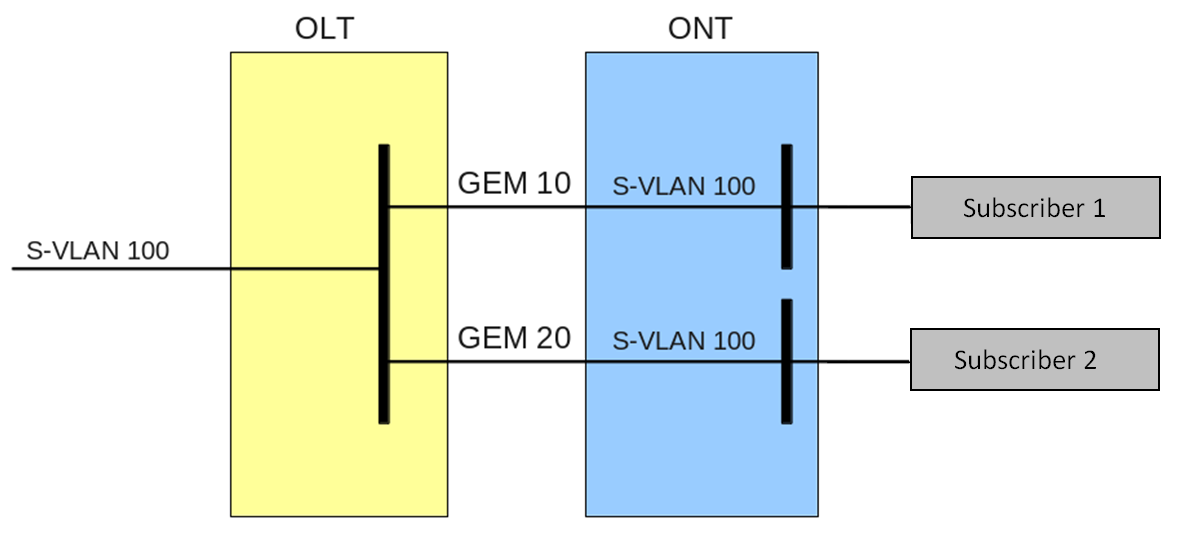
Figure 30 — "VLAN for Service" service model architecture
Operating principle
The configuration model concept is used for implementation of different service models in the terminal. A configuration model defines general principles for data communication channelling for both OLT and ONTs.
- Model 1 is an implementation of the VLAN for Subscriber service model. The model does not have dedicated broadcast GEM ports and uses U-VLAN on the ONT side.
- Model 2 is an implementation of the VLAN for Service service model. This model uses a dedicated broadcast GEM port.
- Model 3 is an implementation of the VLAN for Service service model. This model uses a dedicated broadcast GEM port. It differs from Model 2 by the order of S-VLAN to U-VLAN modification.
Table 26 — Service Models
VLAN for Service | VLAN for Subscriber | Broadcast to Unicast GEM | Dedicated Broadcast GEM | |
|---|---|---|---|---|
Model 1 | - | + | + | - |
Model 2 | + | - | - | + |
Model 3 | + | - | - | + |
Model 1
Consider an example of Model 1 implementation.
The scheme of this service model is shown in the Figure 31.
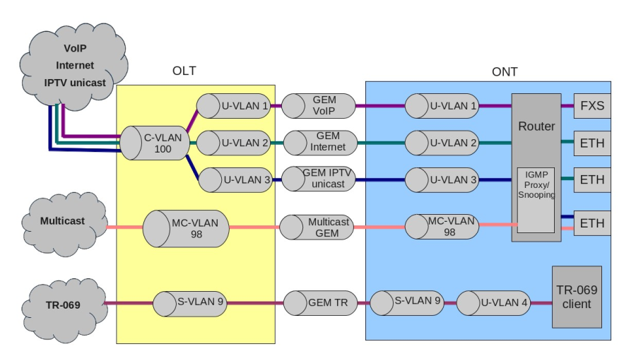
Figure 31 — Service Model 1 scheme
A C-VLAN is used between an ONT and service routers (BRAS, VoIP SR) that encapsulate services for one subscriber (one ONT), such as VoIP, Internet, and IPTV unicast. An S-VLAN that is global for all subscribers (ONTs) is used for the TR-069 management service. Corresponding GEM ports are created for every OLT service between the ONTs and OLT. A dedicated MC-VLAN is used for multicast transmissions.
The OLT casts C-VLAN (for VoIP, Internet, and IPTV unicast) or S-VLAN (for TR-069) for every service into a corresponding U-VLAN. An ONT associates the U-VLAN with corresponding ONT interfaces or program modules. For example, the TR-069 service is associated with a TR-069 client with the help of a corresponding interface. The VoIP, Internet, and IPTV unicast services can operate in the router or bridge modes depending on the ONT configuration. The chart shows all services configured in the router mode.
Broadcast and unknown unicast traffic is transmitted in this model by replicating a corresponding packet (broadcast or unknown unicast) to the OLT. C-VLAN replicates services to all associated GEM ports and at the same time translates data to the corresponding U-VLAN for each service. The TR-069 service is replicated between the corresponding GEM ports of all subscribers (ONTs). Thus, the model implements "VLAN for Subscriber" for the VoIP, Internet, and IPTV unicast services, but uses "VLAN for Service" for the TR-069 service.
Model 2
Consider an example of Model 2 implementation.
The chart of this service model is shown in the following figure.
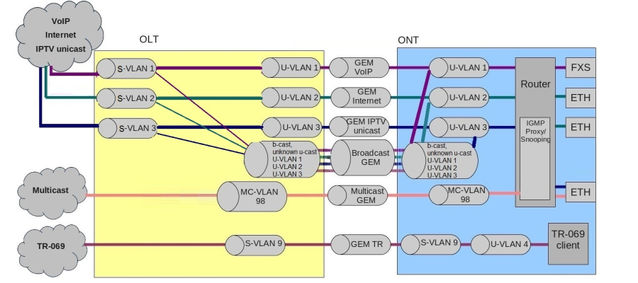
Figure 32 — Service Model 1 scheme
Dedicated S-VLANs are used between the OLT and service routers (BRAS, VoIP SR) for each of the following services: VoIP, Internet, IPTV unicast, TR-069. These S-VLANs are common for all subscribers (ONTs). Corresponding GEM ports are created for every OLT service between the ONTs and OLT. A dedicated MC-VLAN is used for multicast transmissions.
OLT transmits S-VLAN into a corresponding U-VLAN for each service. An ONT associates the U-VLAN with corresponding ONT interfaces or program modules. For example, the TR-069 service is associated with a TR-069 client with the help of a corresponding interface. The VoIP, Internet, and IPTV unicast services can operate in the router or bridge modes depending on the ONT configuration. The chart shows all services configured in the router mode.
All broadcast and unknown unicast traffic is redirected to a dedicated broadcast GEM port in this model. Broadcast and unknown unicast packets are sent to U-VLAN (for the VoIP, Internet, and IPTV unicast services) in the ONT.
This model is similar to Model 3 except the following: transmission of C-VLAN to U-VLAN is performed on the OLT side, while the VoIP, Internet, and IPTV unicast traffic comes to U-VLAN in the ONT.
Thus, the model implements "VLAN for Service" for the VoIP, Internet, IPTV unicast, and TR-069 services.
Model 3
Consider an example of Model 3 implementation.
The chart of this service model is shown in the following figure.
Dedicated S-VLANs are used between the OLT and service routers (BRAS, VoIP SR) for each of the following services: VoIP, Internet, IPTV unicast, TR-069. These S-VLANs are common for all subscribers (ONTs). Corresponding GEM ports are created for every OLT service between the ONTs and OLT. A dedicated MC-VLAN is used for multicast transmissions.
The VoIP, Internet, IPTV, and TR-069 unicast services are associated with S-VLAN in an ONT. The ONT transmits S-VLAN into a corresponding U-VLAN for each service. An ONT associates the U-VLAN with corresponding ONT interfaces or program modules. For example, the TR-069 service is associated with a TR-069 client with the help of a corresponding interface. The VoIP, Internet, and IPTV unicast services can operate in the router or bridge modes depending on the ONT configuration. The chart shows all services configured in the router mode.
All broadcast and unknown unicast traffic is redirected to a dedicated broadcast GEM port in this model. Broadcast and unknown unicast packets come to S-VLAN in the ONT. These packets are transmitted into the corresponding U-VLANs on the ONT side. In this case, broadcast and unknown unicast are replicated neither in the OLT nor in the ONT since every service has a separate S-VLAN for broadcast and unknown unicast traffic.
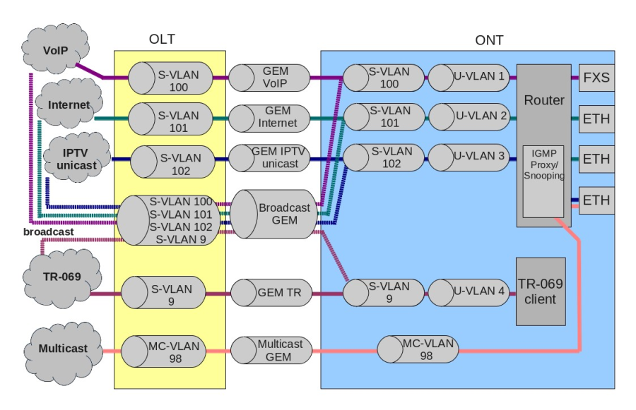
Figure 33 — Service Model 3 scheme
Thus, the model implements "VLAN for Service".
Model configuration
Step 1. Check the current configuration with the help of the show gpon olt configuration command.
LTP-8X# show gpon olt configuration:
.  .  .
Datapath:
Model:	model2
Broadcast gem port:	4095
Multicast gem port:	4094
.  .  .
Step 2. Set the model by using the gpon olt model command.
LTP-8X# configure terminal
LTP-8X(config)# gpon olt model 3
Step 3. Apply the changes by using the commit command.
LTP-8X(config)# do commit
ONT licensing
By default, OLT supports only ELTEX ONTs operation. To enable any third-party ONTs, OLT requires a license. To purchase the license, contact ELTEX Marketing Department.
If a third-party ONT is connected to OLT without a license, the following entry will be made in the log file:
Jul 4 11:10:14 LTP-8X pmchal: error: [ONT2/0] License is not valid, configuration will not continue
Loading a license file to OLT
A license is a text file of the following format:
{
"version":"<VER>",
"type":"all",
"count":"<count>",
"sn":"<SN>",
"mac":"<MAC>",
"sign":"<hash>"
}
Where:
- VER — license file version number;
- count — number of third-party ONTs that can run on OLT;
- SN — LTP serial number;
- MAC — LTP MAC address;
- hash — license file digital signature.
There are two ways to load a license to OLT.
Use the copy command:
LTP-8X# copy tftp://<IP>/<PATH> fs://license
Download file from TFTP-server..
License successfully installed. Please reboot device for changes to make effect
Where:
- IP — TFTP server IP address;
- PATH — license file path on TFTP server.
Use CLI:
LTP-8X# license set """<license>"""
License saved.
License successfully installed.
Where:
license — full content of the license file including curly brackets.
To view information about the license on the device, use the show command.LTP-8X# show license Active license information: License valid: yes Version: 1.2 Board SN: GP2B000022 Licensed vendor: all Licensed ONT count: 10 Licensed ONT online: 3The license file remains after device reload, firmware update, and configuration load. If OLT is reset to factory settings, the license is also deleted.
Deleting a license file from OLT
If necessary, you can delete a previously installed license using the no license command.
LTP-8X# no license
License file removed.
License successfully deleted from system.
LTP-8X# show license
Active license information:
	No license installed
EasyСonfig. EasyMode
LTP-X EasyMode
EasyMode is a function set of LTP optical terminals. EasyMode is dedicated to fast GPON deployment according to realized service model. EasyMode allows providers to configure Triple Play services promptly.
EasyMode can be used for:
- Acquaintance with GPON technology and ELTEX equipment;
- Fast testing of the main capabilities of the equipment;
- Automatic configuring of the equipment on a network.
Software and hardware requirements
The EasyMode is supported by the hardware of B and C revisions and by NTU terminals. For EasyMode operation, it is necessary to use the software no below than:
For LTP-8X(4X) | 3.26.1 |
For NTU-1 | 3.24.0 |
For NTU-2W | 3.25.1 |
For NTU-2V(C), NTU-RG-1402-GW | 3.25.2 |
For NTU-RG-1421(31)G-Wac | 3.28.1 |
Detailed information about the easy configuration mode is contained in the LTP EasyMode manual document, which can be found in the Download Center.
Automatic ONT activation
Automatic activation speeds up the process of adding new ONTs to an existing configuration with the necessary profiles.
Automatic ONT activation configuration
Step 1. Enable automatic ONT activation.
LTP-8X(config)# gpon olt auto-activation ont enable
Step 2. If necessary, specify a template that will be assigned to all auto-activated ONTs by default.
LTP-8X(config)# gpon olt auto-activation ont default template template-00
Step 3. If necessary, specify a template that will be assigned to ONT depending on their type (EquipmentID), during automatic activation.
LTP-8X(config)# gpon olt auto-activation ont type NTU-1 template NTU1_2149
Step 4. If necessary, specify the gpon-port on which this auto-activation rule will trigger.
TP-8X(config)# gpon olt auto-activation ont type NTU-1 template template-00 gpon-port 0-2
Step 5. Apply the changes by using the commit command.
LTP-8X(config)# do commit
After applying the changes, the OLT will reconfigure.
To apply ONT configuration changes that are added automatically, you must enter the rollback command first. Changes will not be made until the command is entered and an error will be issued indicating the need to enter.
ONT configuration
This chapter describes general principles of ONT configuration. It also defines configuration profiles.
ONT is configured with the help of a profile, which defines high-level expression of data communication channels. All operations related to channel creation are performed automatically. The way data communication channels are created depends on the selected service model.
ONT configuration includes assignment of configuration profiles and specification of ONT specific parameters. Configuration profiles allow general parameters to be set for all or for a range of ONTs. Profile parameters may include, for instance, DBA settings, configuration of VLAN operations in OLT and ONT, settings of Ethernet ports in ONT. Specific ONT parameters allow each separate ONT to have its own settings specified. Such settings include, for example, GPON password, subscriber's VLAN, etc.
General principles of configuration
Service is the key term of ONT configuration. This term completely includes a communication channel, through which data is transferred from the interfaces located on the front panel of the terminal (see section Interface configuration) to users' ONT ports. There are two service profiles: cross-connect and dba. The cross-connect profile creates a GEM service port, the dba profile allocates an Alloc-ID for this ONT and associates a corresponding GEM port to the Alloc-ID.
Table 27 — ONT profiles
Profile | Description |
|---|---|
cross-connect | Defines VLAN transformation in OLT and ONT |
dba(alloc) | Defines upstream traffic parameters |
shaping | Defines restrictions for upstream and downstream service traffic |
management | Defines TR-69 management service parameters |
ports | Defines user port groups in ONT as well as IGMP and multicast parameters for user ports |

Figure 34 — ONT scope of operation
ONT profiles configuration
Cross-connect profile configuration
- Step 1. To configure a cross-connect profile, first you need to specify whether the service will be routed (transmitted through an ONT router) or bridged (use bridge connection). This can be done by changing the model parameter.
- Step 2. Then, you need to specify a service type in the type parameter. Some service types require the iphost parameter to be set that allows you to choose a definite instance of IP interface in the ONT.
- Step 3. A VLAN is configured in a cross-connect profile with the help of the following parameters: tag mode, outer vid, outer cos, inner vid, user vid, and user cos.
- Step 4. Tag mode enables upstream Q-in-Q mode; outer vid, outer cos, and inner vid specify internal and external Q-in-Q tags correspondingly. The CoS value of the internal tag is copied from the external one in this case. If the Q-in-Q mode is not used, only the outer vid and outer cos parameters are valid. The user vid and user cos parameters allow a tag to be specified, which will be used on the ONT side.
- Step 5. The mac-table-limit parameter allows restriction of records number in the MAC table of the OLT for this service.
- Step 6. The priority parameter allows allocation of all services of one T-CONT into queues with priorities (if ONT supports this method).
DBA profile configuration
This profile configures dynamic bandwidth allocation (DBA). These parameters allow specification of any T-CONT type described in G.984.3.
- Step 1. First of all, choose sla class to define the basic DBA algorithm.
- Step 2. After that, configure sla status-reporting to define the type of ONT queues status report.
- Step 3. The bandwidth fixed, bandwidth guaranteed, and bandwidth besteffort parameters define the fixed, guaranteed, and best-effort bandwidth correspondingly.
DBA configuration is described in details in DBA configuration.
Shaping profile configuration
Configuration of this profile allows restriction of upstream and downstream services.
- Step 1. Downstream restriction in OLT uses the policing algorithm. The restriction can either use one policer for all services or individual policers for each separate service. This is specified in the one-policer parameter. When one policer is used for all services, only policer 0 should be specified; otherwise, policers for all services should be adjusted.
- Step 2. Upstream restriction in ONT uses the shaping algorithm. You can specify either a global shaper or individual shapers for unicast, multicast, and broadcast traffic (ONT functionality).
The configuration of shaping profile represented detailed in Shaping configuration.
Ports profile configuration
The ports profile allows you to group ports in ONT. The profile also contains IGMP and multicast setting as they are separately adjusted for each port.
You can adjust up to 4 Ethernet ports and a VEIP virtual port, which will serve as a link between the OMCI and RG domains in ONT.
- Step 1. Ethernet ports are grouped with the help of the bridge-group parameter. Value 0 means that the port is associated with the RG domain (router). Other values mean port association with the OMCI domain, i. e. the port can be directly used in OLT to establish a data communication channel.
- Step 2. IGMP and multicast configuration is described in detail in IGMP and MLD configuration in terminal switch.
Management profile configuration
The management profile enables specific configuration of the TR-069 management protocol, namely configuration of a TR-client in ONT.
- Step 1. The omci-configuration parameter defines the TR client configuration which can be done either automatically with DHCP (all other parameters of the profile are not used in this case) or with OMCI using the profile settings.
- Step 2. The url parameter corresponds to the address of the auto configuration server (ACS), which access parameters are defined by the username and password parameters.
The TR-069 protocol configuration is described in detail in VoIP configuration.
Re-defining the parameters set in the cross-connect profile. Custom parameters
In some cases, it is necessary to define unique VLAN ID/802.1p tags for ONT. For solving this problem, you can use custom parameters instead of creating a profile.
Custom svid
LTP-8X# configure terminal
LTP-8X(config)# interface ont 0/0
LTP-8X(config)(if-ont-0/0)# service 0 custom svid 1234
If cross-connect profile defined in the specified service has tag-mode double-tagged, VLAN ID of the external tag will be replaced. For single-tagged service, VLAN ID of the single tag will be replaced.
Custom cvid
LTP-8X# configure terminal
LTP-8X(config)# interface ont 0/0
LTP-8X(config)(if-ont-0/0)# service 0 custom cvid 1234
If cross-connect profile defined in the specified service has tag-mode double-tagged, VLAN ID of the internal tag will be replaced. For single-tagged service, VLAN ID of the single tag will be replaced.
If you set custom svid and cvid simultaneously for single-tagged service, svid will be used for replacing the VLAN ID.
Сustom cos
LTP-8X# configure terminal
LTP-8X(config)# interface ont 0/0
LTP-8X(config)(if-ont-0/0)# service 0 custom cos 3
Replaces 802.1p field in a tag.
ONT configuration procedure
Figure below shows a step-by-step procedure of ONT configuration.
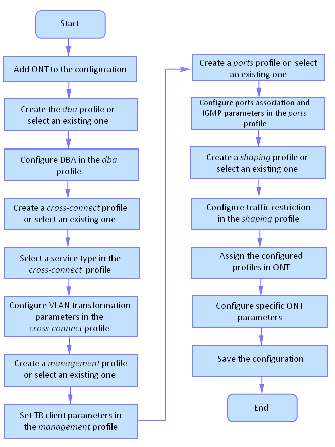
Figure 35 — ONT configuration procedure
Step 1. Prior to proceed to ONT configuration, add an ONT into the OLT configuration. For an ONT to be added and configured, it does not need to be physically connected to the OLT. You can view the list of inactive ONTs with the help of the show interface ont <gpon-port> unactivated command.
LTP-8X# show interface ont 0 unactivated
-----------------------------------
GPON-port 0 ONT unactivated list
-----------------------------------
## Serial      ONT ID Channel Status RSSI[dBm] Version EquipmentID
1 ELTX5C00008C n/a 0  UNACTIVATED	 n/a    n/a	 n/a
2 ELTX1A00001A n/a 0  UNACTIVATED	 n/a    n/a	 n/a
Total ONT count: 2
Step 2. To specify ONT settings, go to the corresponding view with the help of the interface ont command. Specify ONT serial number, password, or their combination.
LTP-8X# configure terminal
LTP-8X(config)# interface ont 0/0
LTP-8X(config)(if-ont-0/0)# serial ELTX5C00008C
LTP-8X(config)(if-ont-0/0)# password 0000000000
NTU-SFP-100 uses PON-Password «default» by default.
Step 3. Apply the configuration by using the commit command.
LTP-8X(config)(if-ont-0/0)# do commit
Step 4. View the ONT configuration by using the do show interface ont 0/0 configuration command.
LTP-8X(config)(if-ont-0/0)# do show interface ont 0/0 configuration
-----------------------------------
						[ONT0/0] configuration
-----------------------------------
Description: ’’
Status: UP
Serial:	ELTX5C00008C
Password: ’0000000000’
Fec up:	false
Downstream broadcast: true
Downstream broadcast filter: true
Ber interval: none
Ber  update  period: 60
Rf port state: disabled
Omci error tolerant: false
Profile shaping: shaping-00			ONT Profile Shaping 0
Profile ports: ports-00			ONT Profile Ports 0
Profile management: unassigned
Custom model: none
Template: unassigned
Model 1
Consider configuration of a data communication channel, which is based on Model 1 and implements "VLAN for Subscriber" (except for the control service, which is implemented in S-VLAN).
Routed mode
Configure the Internet (PPPoE), IPTV unicast, and management services via the TR-069 protocol. Set the VLAN ID for the subscriber to 200, U-VLAN IDs to 10 and 11 for each service respectively. Traffic between the OLT and ONT will be transmitted into VLAN 10 and 11. Multicast traffic will be transmitted to VLAN 98, management will be performed via VLAN 9.
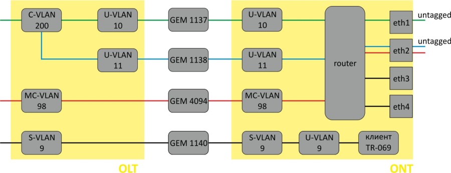
Figure 36 — Routed service abstract representation for Model 1
Step 1. Assign a service model.
LTP-8X# configure terminal
LTP-8X(config)# gpon olt model 1
Step 2. Create an Internet cross-connect profile for the configuration. By default, the profile uses a routed service. Configure a U-VLAN with the help of the user vid command (it equals 10 for the first service in this case).
LTP-8X(config)# profile cross-connect Internet
LTP-8X(config-cross-connect)("Internet")# user vid 10
Step 3. Check the changes made.
LTP-8X(config-cross-connect)("Internet")# do show profile cross-connect
Internet
Name: ’Internet’
Description: ’ONT Profile Cross Connect 1’
Model: ont-rg
Bridge group: -
Tag mode: single-tagged
Outer vid: 1
Outer cos: unused
Inner vid: -
U  vid: 10
U  cos: unused
Mac table entry limit: unlimited
Type: general
Iphost eid: 0
Priority queue: 0
Step 4. By analogy with the described above, create another cross-connect profile (UC_IPTV) for the second service and configure it with U-VLAN 11.
LTP-8X(config)# profile cross-connect UC_IPTV
LTP-8X(config-cross-connect)("UC_IPTV")# user vid 11
Step 5. Check the changes made.
LTP-8X(config-cross-connect)("UC_IPTV")# do show profile cross-connect UC_IPTV
Name: ’UC_IPTV’
Description: ’ONT Profile Cross Connect 2’
Model: ont-rg
Bridge group: -
Tag mode: single-tagged
Outer vid: 1
Outer cos: unused
Inner vid: -
U  vid: 11
U  cos:	unused
Mac table entry limit: unlimited
Type: general
Iphost eid: 0
Priority queue: 0
Use web configurator or ACS to adjust necessary settings for these services in the ONT.
Step 6. Specify DBA parameters. To do this, create a dba profile and adjust the corresponding settings. We set a value of a guaranteed bandwidth in this example.
LTP-8X(config)# profile dba AllServices
LTP-8X(config-dba)("AllServices")# bandwidth guaranteed 500
Step 7. Check the changes made.
LTP-8X(config-dba)("AllServices")# do show profile dba AllServices
    Name:                                              'AllServices'
    Description:                                       'ONT Profile DBA 1'
    Dba:
        Sla data:
            Service class:                             type5
            Status reporting:                          nsr
            Alloc size:                                0
            Alloc period:                              0
            Fixed bandwidth:                           0
            Guaranteed bandwidth:                      500
            Besteffort bandwidth:                      1244000
    T-CONT allocation scheme:                          share T-CONT with same profile
Step 8. To configure multicast traffic, create a ports profile, specify groups allowed for viewing, a VLAN to send IGMP packets, and the rules for relaying multicast traffic in the downstream direction across the VLAN for the UC_IPTV service.
LTP-8X(config)# profile ports Ports1
LTP-8X(config-ports)("Ports1")# igmp multicast dynamic-entry 0 vid 98
LTP-8X(config-ports)("Ports1")# igmp multicast dynamic-entry 0 group 224.0.0.1 239.255.255.255
LTP-8X(config-ports)("Ports1")# veip upstream vid 11
LTP-8X(config-ports)("Ports1")# veip upstream tag-control replace-tag
LTP-8X(config-ports)("Ports1")# veip downstream vid 11
LTP-8X(config-ports)("Ports1")# veip downstream tag-control replace-tag
Step 9. Check the changes made.
LTP-8X(config-ports)("Ports1")# do show profile ports
Ports1
...
        Multicast dynamic entry [0]:
            Vlan id:                                   98
            First group ip:                            224.0.0.1
            Last group ip:                             239.255.255.255

    Veip:
        Multicast enable:                              true
        Multicast port settings:
            Upstream igmp vid:                         11
            Upstream igmp prio:                        0
            Upstream igmp tag control:                 replace tag
            Downstream multicast vid:                  11
            Downstream multicast prio:                 0
            Downstream multicast tag control:          replace tag
            Max groups:                                0
            Max multicast bandwidth:                   0
Step 10. Configure a management profile. To do this, create a cross-connect profile and assign it with the management type.
LTP-8X(config)# profile cross-connect management
LTP-8X(config-cross-connect)("management")# outer vid 9
LTP-8X(config-cross-connect)("management")# type management
Step 11. Check the changes made.
LTP-8X(config-cross-connect)("management")# do show profile cross-connect management
    Name:                                            'management'
    Description:                                     'ONT Profile Cross Connect 2'
    Model:                                           ont-rg
    Bridge group:                                    -
    Tag mode:                                        single-tagged
    Outer vid:                                       9
    Outer cos:                                       unused
    Inner vid:                                       -
    U vid:                                           untagged
    U cos:                                           unused
    Mac table entry limit:                           unlimited
    Type:                                            management
    IP host index:                                   0
    Priority queue:                                  0
Step 12. Assign the created profiles in the ONT.
LTP-8X(config)# interface ont 0/0
LTP-8X(config)(if-ont-0/0)# service 0 profile dba AllServices
LTP-8X(config)(if-ont-0/0)# service 0 profile cross-connect Internet
LTP-8X(config)(if-ont-0/0)# service 1 profile dba AllServices
LTP-8X(config)(if-ont-0/0)# service 1 profile cross-connect UC_IPTV
LTP-8X(config)(if-ont-0/0)# profile ports Ports1
LTP-8X(config)(if-ont-0/0)# service 2 profile dba AllServices
LTP-8X(config)(if-ont-0/0)# service 2 profile cross-connect management
LTP-8X(config)(if-ont-0/0)# do show interface ont 0/0 configuration


-----------------------------------
[ONT0/0] configuration
-----------------------------------

Description: ''
Status: UP
Serial: ELTX5C00008C
...
Service [0]:
Profile cross connect: Internet 	ONT Profile Cross Connect 1
Profile dba: AllServices 		ONT Profile DBA 1
Service [1]:
Profile cross connect: UC_IPTV 	ONT Profile Cross Connect 2
Profile dba: AllServices 		ONT Profile DBA 1
Service [2]:
Profile cross connect: management 	ONT Profile Cross Connect 3
Profile dba: AllServices 		ONT Profile DBA 1
...
Profile ports: Ports1 		ONT Profile Ports 1
Step 13. VLAN for Subscriber requires a C-VLAN to be assigned for this ONT (subscriber). Assign S-VLAN 200 for the Internet and IPTV services by using the service X custom command (where X – service number). The management service operates in an S-VLAN, therefore no C-VLAN is defined for this service.
LTP-8X(config)(if-ont-0/0)# service 0 custom cvid 200
LTP-8X(config)(if-ont-0/0)# service 1 custom cvid 200
LTP-8X(config)(if-ont-0/0)# do show interface ont 0/0 configuration
...
Service [0]:
		Profile  cross  connect: Internet	ONT  Profile Cross  Connect  1
		Profile dba: AllServices		ONT Profile DBA 1
		Custom svlan: 200
		Custom CoS: unused
	Service [1]:
		Profile  cross  connect: UC_IPTV
		Profile dba: AllServices		ONT Profile DBA 1
		Custom svlan: 200
		Custom CoS: Unused
Step 14. Apply the changes by using the commit command.
LTP-8X(config)(if-ont-0/0)# do commit
Step 15. Configure VLAN 200, 201, 9, and 98 in the switch view (see VLAN configuration).
LTP-8X# switch
LTP-8X(switch)# configure terminal
LTP-8X(switch)(config)# vlan 200,201,98,9
LTP-8X(switch)(config-vlan-range)# tagged front-port 0
LTP-8X(switch)(config-vlan-range)# tagged pon-port 0 – 7
LTP-8X(switch)(config-vlan-range)# exit
LTP-8X(switch)(config)# commit
LTP-8X(switch)(config)# exit
Step 16. Configure IGMP Proxy in the switch view for VLAN 98, enable the IGMP Proxy mode globally, and set the range of allowed IGMP groups. Also, enable IGMP snooping globally.
LTP-8X# switch
LTP-8X(switch)# configure terminal
LTP-8X(switch)(config)# ip igmp snooping
LTP-8X(switch)(config)# ip igmp proxy report range 232.1.0.1 232.1.0.100 from all to 98
LTP-8X(switch)(config)# ip igmp proxy report enable
LTP-8X(switch)(config)# commit
LTP-8X(switch)(config)# exit
Bridged mode
Configure the Internet (PPPoE), IPTV unicast, and management services via the TR-069 protocol. Set the subscriber VLAN ID to 200. Configure transmission of tagged traffic to LAN port 1. To do this, set the U-VLAN ID to 10. Traffic to port 2 will be transmitted untagged. Multicast traffic will be transmitted to VLAN 98, management will be performed via VLAN 9.
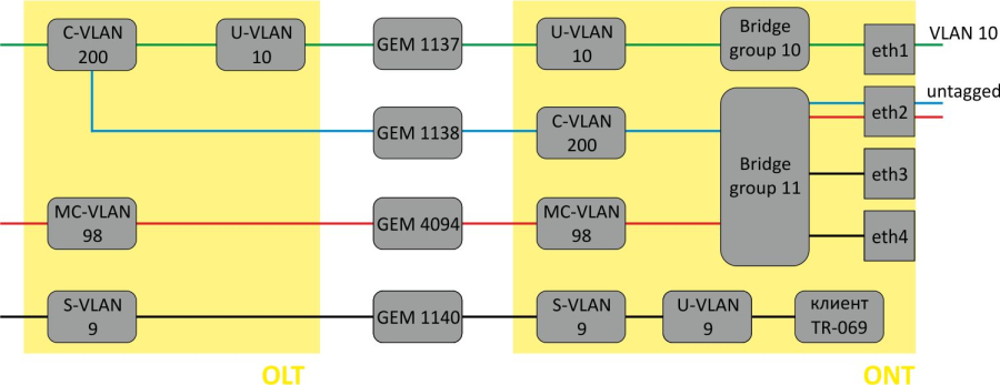
Figure 37 — Bridged service abstract representation for Model 1
Step 1. Create an Internet cross-connect profile to configure PPPoE in the bridge. Configure the bridged service specifying the bridge group the ONT port will be connected to (in this case, it is equal to 10 for the first service), define a U-VLAN for transmission of tagged traffic to the port.
LTP-8X(config)# profile cross-connect Internet
LTP-8X(config-cross-connect)("Internet")# bridge
LTP-8X(config-cross-connect)("Internet")# bridge group 10
LTP-8X(config-cross-connect)("Internet")# user vid 10
Step 2. Check the changes made.
LTP-8X(config-cross-connect)("Internet")# do show profile cross-connect Internet
    Name:                                              'Internet'
    Description:                                       'ONT Profile Cross Connect 1'
    Model:                                             ont
    Bridge group:                                      10
    Tag mode:                                          single-tagged
    Outer vid:                                         1
    Outer cos:                                         unused
    Inner vid:                                         -
    U vid:                                             untagged
    U cos:                                             unused
    Mac table entry limit:                             unlimited
    Type:                                              general
    IP host index:                                     0
    Priority queue:                                    0
Step 3. By analogy with the described above, create another cross-connect profile (UC_IPTV) for the second service and configure it with bridge group 11.
LTP-8X(config)# profile cross-connect UC_IPTV
LTP-8X(config-cross-connect)("UC_IPTV")# bridge
LTP-8X(config-cross-connect)("UC_IPTV")# bridge group 11
Step 4. Check the changes made.
LTP-8X(config-cross-connect)("UC_IPTV")# do show profile cross-connect UC_IPTV
    Name:                                              'UC_UPTV'
    Description:                                       'ONT Profile Cross Connect 2'
    Model:                                             ont
    Bridge group:                                      11
    Tag mode:                                          single-tagged
    Outer vid:                                         1
    Outer cos:                                         unused
    Inner vid:                                         -
    U vid:                                             untagged
    U cos:                                             unused
    Mac table entry limit:                             unlimited
    Type:                                              general
    IP host index:                                     0
    Priority queue:                                    0
Step 5. Specify DBA parameters. To do this, create a dba profile and adjust the corresponding settings. We set a value of a guaranteed bandwidth in this example.
LTP-8X(config)# profile dba AllServices
LTP-8X(config-dba)("AllServices")# bandwidth guaranteed 500
Step 6. Check the changes made.
LTP-8X(config-dba)("AllServices")# do show profile dba AllServices
    Name:                                              'AllServices'
    Description:                                       'ONT Profile DBA 1'
    Dba:
        Sla data:
            Service class:                             type5
            Status reporting:                          nsr
            Alloc size:                                0
            Alloc period:                              0
            Fixed bandwidth:                           0
            Guaranteed bandwidth:                      500
            Besteffort bandwidth:                      1244000
    T-CONT allocation scheme:                       share T-CONT with same profile
Step 7. Associate the bridge group with an ONT port. To do this, create a ports profile and set the bridge group parameter to 10 for the eth0 port and to 11 for the eth1 port. Set the rules of multicast traffic processing for port 1.
LTP-8X(config)# profile ports Ports1
LTP-8X(config-ports)("Ports1")# port 0 bridge group 10
LTP-8X(config-ports)("Ports1")# port 1 bridge group 11
LTP-8X(config-ports)("Ports1")# igmp multicast dynamic-entry 0 vid 98
LTP-8X(config-ports)("Ports1")# igmp multicast dynamic-entry 0 group 224.0.0.1 239.255.255.255
LTP-8X(config-ports)("Ports1")# port 1 multicast
LTP-8X(config-ports)("Ports1")# port 1 igmp downstream vid 98
LTP-8X(config-ports)("Ports1")# port 1 igmp downstream tag-control remove-tag
Step 8. Check the changes made.
LTP-8X(config-ports)("Ports1")# do show profile ports Ports1
...
    Igmp settings:
...
        Multicast dynamic entry [0]:
            Vlan id:                                   98
            First group ip:                            224.0.0.1
            Last group ip:                             239.255.255.255
...
    Port [0]:
        Speed:                                         auto
        Duplex:                                        auto
        Bridge group:                                  10
        Spanning tree for bridge group:                false
        Multicast enable:                              true
        Multicast port settings:

            Upstream igmp vid:                         1
            Upstream igmp prio:                        0
            Upstream igmp tag control:                 pass
            Downstream multicast vid:                  1
            Downstream multicast prio:                 0
            Downstream multicast tag control:          pass
            Max groups:                                0
            Max multicast bandwidth:                   0
        Shaper downstream:
            Enable:                                    false
            Commited rate:                             1000000
        Shaper upstream:
            Enable:                                    false
            Commited rate:                             1000000
    Port [1]:
        Speed:                                         auto
        Duplex:                                        auto
        Bridge group:                                  11
        Spanning tree for bridge group:                false
        Multicast enable:                              false
        Multicast port settings:
            Upstream igmp vid:                         1
            Upstream igmp prio:                        0
            Upstream igmp tag control:                 pass
            Downstream multicast vid:                  98
            Downstream multicast prio:                 0
            Downstream multicast tag control:          remove-tag
            Max groups:                                0
            Max multicast bandwidth:                   0
        Shaper downstream:
            Enable:                                    false
            Commited rate:                             1000000
        Shaper upstream:
            Enable:                                    false
            Commited rate:                             1000000
Step 9. Configure a management profile. To do this, create a cross-connect profile and assign it with the management type and the bridge model.
LTP-8X(config)# profile cross-connect management
LTP-8X(config-cross-connect)("management")# bridge
LTP-8X(config-cross-connect)("management")# outer vid 9
LTP-8X(config-cross-connect)("management")# type management
Step 10. Check the changes made.
LTP-8X(config-cross-connect)("management")# do show profile cross-connect management
    Name:                                            'management'
    Description:                                     'ONT Profile Cross Connect 2'
    Model:                                             ont
    Bridge group:                                      255
    Tag mode:                                          single-tagged
    Outer vid:                                         9
    Outer cos:                                         unused
    Inner vid:                                         -
    U vid:                                             untagged
    U cos:                                             unused
    Mac table entry limit:                             unlimited
    Type:                                              management
    IP host index:                                     0
    Priority queue:                                    0
Step 11. Assign the created profiles in the ONT.
LTP-8X(config)# interface ont 0/0
LTP-8X(config)(if-ont-0/0)# service 0 profile dba AllServices
LTP-8X(config)(if-ont-0/0)# service 0 profile cross-connect Internet
LTP-8X(config)(if-ont-0/0)# service 1 profile dba AllServices
LTP-8X(config)(if-ont-0/0)# service 1 profile cross-connect UC_IPTV
LTP-8X(config)(if-ont-0/0)# service 2 profile dba AllServices
LTP-8X(config)(if-ont-0/0)# service 2 profile cross-connect management
LTP-8X(config)(if-ont-0/0)# profile ports Ports1
LTP-8X(config)(if-ont-0/0)# do show interface ont 0/0 configuration
-----------------------------------
[ONT0/0] configuration
-----------------------------------

    Description:                     ''
    Enabled:                         true
    Serial:                          ELTX5C00008C
    Password:                        '0000000000'
    Fec up:                          false
    Easy mode:                       false
    Downstream broadcast:            true
    Downstream broadcast filter:     true
    Ber interval:                    none
    Ber update period:               60
    Rf port state:                   disabled
    Omci error tolerant:             false
Service [0]: Profile cross connect: Internet ONT Profile Cross Connect 1 Profile dba: AllServices ONT Profile DBA 1 Custom cross connect: disabled Service [1]: Profile cross connect: UC_IPTV ONT Profile Cross Connect 2 Profile dba: AllServices ONT Profile DBA 1 Custom cross connect: disabled Service [2]: Profile cross connect: management ONT Profile Cross Connect 3 Profile dba: AllServices ONT Profile DBA 1 Custom cross connect: disabled Profile shaping: shaping-00 ONT Profile Shaping 0 Profile ports: Ports1 ONT Profile Ports 1 Profile management: unassigned Template: unassigned Pppoe sessions unlimited: falseStep 12. VLAN for Subscriber requires a C-VLAN to be assigned for this ONT (subscriber). Assign unique VLAN ID 200 for the Internet and IPTV services by using the service X custom command (where X — service number). The management service operates in an S-VLAN, therefore, settings from the profile are used for the service.
LTP-8X(config)(if-ont-0/0)# service 0 custom svid 200
LTP-8X(config)(if-ont-0/0)# service 1 custom svid 200
LTP-8X(config)(if-ont-0/0)# do show interface ont 0/0 configuration
...

 Service [0]:
        Profile cross connect:                Service1sh          ONT Profile Cross Connect 1
        Profile dba:                          AllServices       ONT Profile DBA 1
        Custom cross connect:                 enabled
            Custom s-vid:                     200
            Custom c-vid:                     unused
            Custom CoS:                       unused
Step 13. Apply the changes by using the commit command.
LTP-8X(config)(if-ont-0/0)# do commit
Step 14. Configure VLAN 200 in the switch view (see VLAN configuration).
LTP-8X# switch
LTP-8X(switch)# configure terminal
LTP-8X(switch)(config)# vlan 200
LTP-8X(switch)(config-vlan)# tagged front-port 0
LTP-8X(switch)(config-vlan)# tagged pon-port 0 – 7
LTP-8X(switch)(config-vlan)# exit
LTP-8X(switch)(config)# commit
LTP-8X(switch)(config)# exit
Step 15. Configure IGMP Proxy in the switch view for VLAN 98, enable the IGMP Proxy mode globally, and set the range of allowed IGMP groups. Also, enable IGMP snooping globally.
LTP-8X# switch
LTP-8X(switch)# configure terminal
LTP-8X(switch)(config)# ip igmp proxy report enable
LTP-8X(switch)(config)# ip igmp proxy report range 232.1.0.1 232.1.0.100 from all to 98
LTP-8X(switch)(config)# ip igmp snooping
LTP-8X(switch)(config)# commit
LTP-8X(switch)(config)# exit
Model 2
Model 2 is a hybrid of Model 1 and Model 3. It is based on «VLAN for Service». Model 2 services configuration is similar to Model 3.
Model 3
Consider configuration of ONT data communication for Model 3, which implements the «VLAN for Service» principle.
Routed mode
Configure the Internet (PPPoE), IPTV unicast, and management services via the TR-069 protocol. Set the VLAN ID to 200 for Internet, to 201 for IPTV unicast. Services will be provided by operator in these VLANs. Set U-VLANs to 200 and 201 for each service respectively. These VLANs will transmit traffic to the subscriber device. Multicast traffic will be transmitted to VLAN 98, management will be performed via VLAN 9.
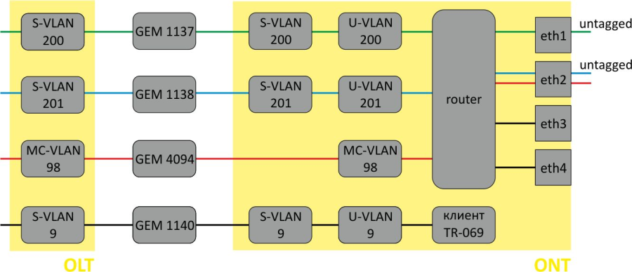
Figure 38 — Routed service abstract representation for Model 3
Step 1. Assign a service model.
LTP-8X# configure terminal
LTP-8X(config)# gpon olt model 3
Step 2. Create an Internet cross-connect profile for the configuration. By default, the profile uses a routed service. Configure a U-VLAN with the help of the u-vid command (it equals 200 for the first service in this case). To assign an S-VLAN, use the outer vid 200 command.
LTP-8X(config)# profile cross-connect Internet
LTP-8X(config-cross-connect)("Internet")# user vid 200
LTP-8X(config-cross-connect)("Internet")# outer vid 200
Step 3. Check the changes made.
LTP-8X(config-cross-connect)("Internet")# do show profile cross-connect Internet
    Name:                                            'Internet'
    Description:                                     'ONT Profile Cross Connect 1'
    Model:                                             ont-rg
    Bridge group:                                      -
    Tag mode:                                          single-tagged
    Outer vid:                                         200
    Outer cos:                                         unused
    Inner vid:                                         -
    U vid:                                             200
    U cos:                                             unused
    Mac table entry limit:                             unlimited
    Type:                                              general
    IP host index:                                     0
    Priority queue:                                    0
Step 4. By analogy with the described above, create another cross-connect profile (UC_IPTV) for the second service and configure it with U-VLAN 201, S-VLAN 201.
LTP-8X(config)# profile cross-connect UC_IPTV
LTP-8X(config-cross-connect)("UC_IPTV")# user vid 201
LTP-8X(config-cross-connect)("UC_IPTV")# outer vid 201
Step 5. Check the changes made.
LTP-8X(config-cross-connect)("UC_IPTV")# do show profile cross-connect UC_IPTV
    Name:                                            'UC_IPTV'
    Description:                                     'ONT Profile Cross Connect 2'
    Model:                                             ont-rg
    Bridge group:                                      -
    Tag mode:                                          single-tagged
    Outer vid:                                         201
    Outer cos:                                         unused
    Inner vid:                                         -
    U vid:                                             201
    U cos:                                             unused
    Mac table entry limit:                             unlimited
    Type:                                              general
    IP host index:                                     0
    Priority queue:                                    0
Step 6. Specify DBA parameters. To do this, create a dba profile and adjust the corresponding settings. We set a value of a guaranteed bandwidth in this example.
LTP-8X(config)# profile dba AllServices
LTP-8X(config-dba)("AllServices")# bandwidth guaranteed 500
Step 7. Check the changes made.
LTP-8X(config-dba)("AllServices")# do show profile dba AllServices
    Name:                                              'AllServices'
    Description:                                       'ONT Profile DBA 1'
    Dba:
        Sla data:
            Service class:                             type5
            Status reporting:                          nsr
            Alloc size:                                0
            Alloc period:                              0
            Fixed bandwidth:                           0
Step 8. To configure multicast traffic, create a cross-connect profile and set the VLAN intended for multicast transmission as an S-VLAN and U-VLAN.
LTP-8X(config)# profile cross-connect MC_IPTV
LTP-8X(config-cross-connect)("MC_IPTV")# user vid 98
LTP-8X(config-cross-connect)("MC_IPTV")# outer vid 98
Step 9. Check the changes made.
LTP-8X(config-cross-connect)("MC_IPTV")# do show profile cross-connect MC_IPTV
    Name:                                            'MC_IPTV'
    Description:                                     'ONT Profile Cross Connect 3'
    Model:                                             ont-rg
    Bridge group:                                      -
    Tag mode:                                          single-tagged
    Outer vid:                                         98
    Outer cos:                                         unused
    Inner vid:                                         -
    U vid:                                             98
    U cos:                                             unused
    Mac table entry limit:                             unlimited
    Type:                                              general
    IP host index:                                     0
    Priority queue:                                    0
Use web configurator or ACS to adjust necessary settings for these services in the ONT.
Step 10. After that, to configure multicast traffic, create a ports profile, specify groups allowed for viewing, a VLAN to send IGMP packets, and the rules for relaying multicast traffic in the downstream direction across the VLAN for the UC_IPTV service.
LTP-8X(config)# profile ports Ports1
LTP-8X(config-ports)("Ports1")# igmp multicast dynamic-entry 0 vid 98
LTP-8X(config-ports)("Ports1")# igmp multicast dynamic-entry 0 group 224.0.0.1 239.255.255.255
LTP-8X(config-ports)("Ports1")# veip upstream vid 98
LTP-8X(config-ports)("Ports1")# veip upstream tag-control replace-tag
LTP-8X(config-ports)("Ports1")# veip downstream vid 98
LTP-8X(config-ports)("Ports1")# veip downstream tag-control replace-tag
Step 11. Check the changes made.
LTP-8X(config-ports)("Ports1")# do show profile ports Ports1
...
    Igmp settings:
        Multicast dynamic entry [0]:
            Vlan id:                                   98
            First group ip:                            224.0.0.1

                    Last group ip:                             239.255.255.255
...
    Veip:
        Multicast enable:                              false
        Multicast port settings:
            Upstream igmp vid:                         98
            Upstream igmp prio:                        0
            Upstream igmp tag control:                 replace-tag
            Downstream multicast vid:                  98
            Downstream multicast prio:                 0
            Downstream multicast tag control:          replace-tag
            Max groups:                                0
            Max multicast bandwidth:                   0
...
Step 12. Configure a management profile. To do this, create a cross-connect profile and assign it with the management type.
LTP-8X(config)# profile cross-connect management
LTP-8X(config-cross-connect)("management")# outer vid 9
LTP-8X(config-cross-connect)("management")# type management
Step 13. Check the changes made.
LTP-8X(config-cross-connect)("management")# do show profile cross-connect management
    Name:                                            'management'
    Description:                                     'ONT Profile Cross Connect 4'
    Model:                                             ont-rg
    Bridge group:                                      -
    Tag mode:                                          single-tagged
    Outer vid:                                         9
    Outer cos:                                         unused
    Inner vid:                                         -
    U vid:                                             untagged
    U cos:                                             unused
    Mac table entry limit:                             unlimited
    Type:                                              management
    IP host index:                                     0
    Priority queue:                                    0
Step 14. Assign the created profiles in the ONT.
LTP-8X(config)# interface ont 0/0 LTP-8X(config)(if-ont-0/0)# service 0 profile dba AllServices LTP-8X(config)(if-ont-0/0)# service 0 profile cross-connect Internet LTP-8X(config)(if-ont-0/0)# service 1 profile dba AllServices LTP-8X(config)(if-ont-0/0)# service 1 profile cross-connect UC_IPTV LTP-8X(config)(if-ont-0/0)# profile ports Ports1 LTP-8X(config)(if-ont-0/0)# service 2 profile dba AllServices LTP-8X(config)(if-ont-0/0)# service 2 profile cross-connect management LTP-8X(config)(if-ont-0/0)# service 3 profile dba AllServices LTP-8X(config)(if-ont-0/0)# service 3 profile cross-connect MC_IPTV
Step 15. Check the changes made.
LTP-8X(config)(if-ont-0/0)# do show interface ont 0/0 configuration ----------------------------------- [ONT0/0] configuration ----------------------------------- Description: '' Enabled: true Serial: ELTX5C00008C Password: '0000000000' Fec up: false Easy mode: false Downstream broadcast: true Downstream broadcast filter: true Ber interval: none Ber update period: 60 Rf port state: disabled Omci error tolerant: false Service [0]: Profile cross connect: Internet ONT Profile Cross Connect 1 Profile dba: AllServices ONT Profile DBA 1 Custom cross connect: disabledService [1]: Profile cross connect: UC_IPTV ONT Profile Cross Connect 2 Profile dba: AllServices ONT Profile DBA 1 Custom cross connect: disabled Service [2]: Profile cross connect: management ONT Profile Cross Connect 3 Profile dba: AllServices ONT Profile DBA 1 Custom cross connect: disabled Profile shaping: shaping-00 ONT Profile Shaping 0 Profile ports: Ports1 ONT Profile Ports 1 Profile management: unassigned Template: unassigned Pppoe sessions unlimited: false LTP-8X(config)(if-ont-0/0)# do show interface ont 0/0 configurationStep 16. Configure VLAN 200, 201, 9 and 98 in the switch view (see VLAN configuration).
LTP-8X# switch LTP-8X(switch)# configure terminal LTP-8X(switch)(config)# vlan 200,201,98,9 LTP-8X(switch)(config-vlan-range)# tagged front-port 0 LTP-8X(switch)(config-vlan-range)# tagged pon-port 0 – 7 LTP-8X(switch)(config-vlan-range)# exit LTP-8X(switch)(config)# commit LTP-8X(switch)(config)# exit
Step 17. Configure IGMP Proxy in the switch view for VLAN 98, enable the IGMP Snooping and IGMP Proxy mode globally, and set the range of allowed IGMP groups.
LTP-8X# switch LTP-8X(switch)# configure terminal LTP-8X(switch)(config)# ip igmp proxy report enable LTP-8X(switch)(config)# ip igmp proxy report range 232.1.0.1 232.1.0.100 from all to 98 LTP-8X(switch)(config)# ip igmp snooping LTP-8X(switch)(config)# commit LTP-8X(switch)(config)# exit
Bridged mode
Configure the Internet (PPPoE), IPTV unicast, and management services via the TR-069 protocol. Set the VLAN ID to 200 for Internet, to 201 for UC_IPTV. Set U-VLAN to 200 for Internet. Multicast traffic will be transmitted to VLAN 98, management will be performed via VLAN 9.
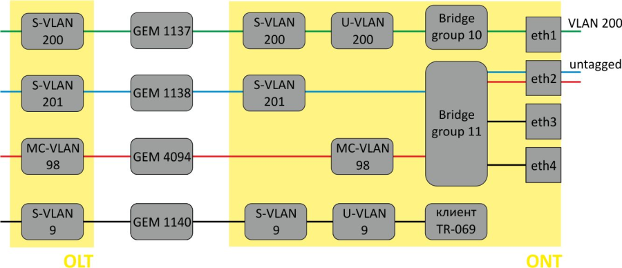
Figure 39 — Bridged service abstract representation for Model 3
Step 1. Create an Internet cross-connect profile to configure PPPoE in the bridge. Configure the bridged service specifying the bridge group the ONT port will be connected to (in this case, it is equal to 10 for the first service).
LTP-8X(config)# profile cross-connect Internet LTP-8X(config-cross-connect)("Internet")# bridge LTP-8X(config-cross-connect)("Internet")# bridge group 10Step 2. To assign an S-VLAN, use the outer vid 200 command: The LAN port of the ONT will send tagged traffic. To enable this, set U-VLAN equal to S-VLAN.
LTP-8X(config-cross-connect)("Internet")# outer vid 200 LTP-8X(config-cross-connect)("Internet")# user vid 200Step 3. Check the changes made.
LTP-8X(config-cross-connect)("Internet")# do show profile cross-connect Internet Name: 'Internet' Description: 'ONT Profile Cross Connect 1' Model: ont Bridge group: 10 Tag mode: single-tagged Outer vid: 200 Outer cos: unusedInner vid: - U vid: 200 U cos: unused Mac table entry limit: unlimited Type: general IP host index: 0 Priority queue: 0Step 4. By analogy with the described above, create another cross-connect profile (UC_IPTV) for the second service and configure it with bridge group 11 and S-VLAN 201.
LTP-8X(config)# profile cross-connect UC_IPTV LTP-8X(config-cross-connect)("UC_IPTV")# bridge LTP-8X(config-cross-connect)("UC_IPTV")# bridge group 11 LTP-8X(config-cross-connect)("UC_IPTV")# outer vid 201Step 5. Set U-VID to untagged to have untagged traffic outgoing from the ONT port.
LTP-8X(config-cross-connect)("UC_IPTV")# user vid untaggedStep 6. Check the changes made.
LTP-8X(config-cross-connect)("UC_IPTV")# do show profile cross-connect UC_IPTV Name: 'UC_IPTV' Description: 'ONT Profile Cross Connect 2' Model: ont Bridge group: 10 Tag mode: single-tagged Outer vid: 201 Outer cos: unused Inner vid: - U vid: untagged U cos: unused Mac table entry limit: unlimited Type: general IP host index: 0 Priority queue: 0Step 7. Specify DBA parameters. To do this, create a dba profile and adjust the corresponding settings. We set a value of a guaranteed bandwidth in this example.
LTP-8X(config)# profile dba AllServices LTP-8X(config-dba)("AllServices")# bandwidth guaranteed 500Step 8. Check the changes made.
LTP-8X(config-dba)("AllServices")# do show profile dba AllServices Name: 'AllServices' Description: 'ONT Profile DBA 1' Dba: Sla data:Service class: type5 Status reporting: nsr Alloc size: 0 Alloc period: 0 Fixed bandwidth: 0 Guaranteed bandwidth: 500 Besteffort bandwidth: 1244000 T-CONT allocation scheme: share T-CONT with same profileStep 9. Associate the bridge group with an ONT port. To do this, create a ports profile and set the bridge group parameter to 10 for the eth0 port and to 11 for the eth1 port. Set the rules of multicast traffic processing for port 1.
LTP-8X(config)# profile ports Ports1 LTP-8X(config-ports)("Ports1")# port 0 bridge group 10 LTP-8X(config-ports)("Ports1")# port 1 bridge group 11 LTP-8X(config-ports)("Ports1")# igmp multicast dynamic-entry 0 vid 98 LTP-8X(config-ports)("Ports1")# igmp multicast dynamic-entry 0 group 224.0.0.1 239.255.255.255 LTP-8X(config-ports)("Ports1")# port 1 multicast LTP-8X(config-ports)("Ports1")# port 1 igmp downstream vid 98 LTP-8X(config-ports)("Ports1")# port 1 igmp downstream tag-control remove-tagStep 10. Check the changes made.
LTP-8X(config-ports)("Ports1")# do show profile ports Ports1 ... Igmp settings: ... Multicast dynamic entry [0]: Vlan id: 98 First group ip: 224.0.0.1 Last group ip: 239.255.255.255 ... Port [0]: Speed: auto Duplex: auto Bridge group: 10 Spanning tree for bridge group: false Multicast enable: true Multicast port settings: Upstream igmp vid: 1 Upstream igmp prio: 0 Upstream igmp tag control: pass Downstream multicast vid: 1 Downstream multicast prio: 0 Downstream multicast tag control: pass Max groups: 0 Max multicast bandwidth: 0 Shaper downstream: Enable: false Commited rate: 1000000 Shaper upstream: Enable: false Commited rate: 1000000Port [1]: Speed: auto Duplex: auto Bridge group: 11 Spanning tree for bridge group: false Multicast enable: false Multicast port settings: Upstream igmp vid: 1 Upstream igmp prio: 0 Upstream igmp tag control: pass Downstream multicast vid: 98 Downstream multicast prio: 0 Downstream multicast tag control: remove-tag Max groups: 0 Max multicast bandwidth: 0 Shaper downstream: Enable: false Commited rate: 1000000 Shaper upstream: Enable: false Commited rate: 1000000 ...Step 11. Configure a management profile. To do this, create a cross-connect profile and assign it with the management type and the bridge model.
LTP-8X(config)# profile cross-connect management LTP-8X(config-cross-connect)("management")# bridge LTP-8X(config-cross-connect)("management")# outer vid 9 LTP-8X(config-cross-connect)("management")# type managementStep 12. Check the changes made.
LTP-8X(config-cross-connect)("management")# do show profile cross-connect management Name: 'management' Description: 'ONT Profile Cross Connect 3' Model: ont Bridge group: 255 Tag mode: single-tagged Outer vid: 9 Outer cos: unused Inner vid: - U vid: untagged U cos: unused Mac table entry limit: unlimited Type: management IP host index: 0 Priority queue: 0Step 13. Assign the created profiles in the ONT.
LTP-8X(config)# interface ont 0/0 LTP-8X(config)(if-ont-0/0)# service 0 profile dba AllServices LTP-8X(config)(if-ont-0/0)# service 0 profile cross-connect Internet LTP-8X(config)(if-ont-0/0)# service 1 profile dba AllServices LTP-8X(config)(if-ont-0/0)# service 1 profile cross-connect UC_IPTV LTP-8X(config)(if-ont-0/0)# service 2 profile dba AllServices LTP-8X(config)(if-ont-0/0)# service 2 profile cross-connect management LTP-8X(config)(if-ont-0/0)# profile ports Ports1 LTP-8X(config)(if-ont-0/0)# do show interface ont 0/0 configuration ----------------------------------- [ONT0/0] configuration ----------------------------------- Description: '' Enabled: true Serial: ELTX5C00008C Password: '0000000000' Fec up: false Easy mode: false Downstream broadcast: true Downstream broadcast filter: true Ber interval: none Ber update period: 60 Rf port state: disabled Omci error tolerant: false Service [0]: Profile cross connect: Internet ONT Profile Cross Connect 1 Profile dba: AllServices ONT Profile DBA 1 Custom cross connect: disabled Service [1]: Profile cross connect: UC_IPTV ONT Profile Cross Connect 2 Profile dba: AllServices ONT Profile DBA 1 Custom cross connect: disabled Service [2]: Profile cross connect: management ONT Profile Cross Connect 3 Profile dba: AllServices ONT Profile DBA 1 Custom cross connect: disabled Profile shaping: shaping-00 ONT Profile Shaping 0 Profile ports: Ports1 ONT Profile Ports 1 Profile management: unassigned Template: unassigned Pppoe sessions unlimited: falseStep 14. Apply the changes by using the commit command.
LTP-8X(config)(if-ont-0/1)# do commit
Step 15. Configure VLAN 200, 201, 9 and 98 in the switch view (see VLAN configuration).
LTP-8X# switch LTP-8X(switch)# configure terminal LTP-8X(switch)(config)# vlan 200,201,98,9 LTP-8X(switch)(config-vlan-range)# tagged front-port 0 LTP-8X(switch)(config-vlan-range)# tagged pon-port 0 – 7 LTP-8X(switch)(config-vlan-range)# exit LTP-8X(switch)(config)# commit LTP-8X(switch)(config)# exit
Step 16. Configure IGMP Proxy in the switch view for VLAN 98, enable the IGMP Snooping and IGMP Proxy mode globally, and set the range of allowed IGMP groups.
LTP-8X# switch LTP-8X(switch)# configure terminal LTP-8X(switch)(config)# ip igmp proxy report enable LTP-8X(switch)(config)# ip igmp proxy report range 232.1.0.1 232.1.0.100 from all to 98 LTP-8X(switch)(config)# ip igmp snooping LTP-8X(switch)(config)# commit LTP-8X(switch)(config)# exit
Tunnelling configuration
Usual profiles in the tag-mode, single-tag or double-tag modes are aimed at mapping the traffic, which is transmitted to the gem port and tagged as user vid or untagged, into the traffic tagged outer vid or outer:inner vid respectively.
Models 2 and 3 allow traffic tunnelling configuration, which extends the range of possible GPON applications in operator's network.
Using the profiles tagged as selective-tunnel allows a tag to be added to incoming packets with a certain set of user vid tags. The profiles tagged as tunnel allow a tag to be added to incoming packets with any user-vid tags.
Consider the following diagram and its configuration as an example.
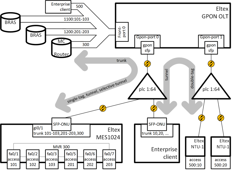
Figure 40 — Communication diagram
VLAN 300 (multicast) and Q-in-Q VLAN 1100 and 1200 (Internet) come to the uplink OLT. It is necessary to let them pass to the switch integrated in the OLT via SFP-ONU. In addition, a corporate client is connected to the splitter via SFP-ONU that sends a random set of VLANs to be passed to remote devices after removing tags of these VLANs at the ONT LAN port. To organise a tunnel for this client, VLAN 500 is selected in the operator's network.
Consider the procedure of OLT configuration for the above diagram.
Step 1. Configure the switch.
interface pon-port 0 bridging to pon-port 1 exit interface pon-port 1 bridging to pon-port 0 exit vlan 300 name VLAN0300 tagged pon-port 0 , front-port 0 exit vlan 500 name VLAN0500 tagged pon-port 0 , pon-port 1 , front-port 0 exit vlan 1100 name VLAN1100 tagged pon-port 0 , front-port 0 exit
vlan 1200 name VLAN1200 tagged pon-port 0 , front-port 0 exit
Step 2. Configure cross-connect profiles.
profile cross-connect "cc-tunnel" bridge bridge group "10" tag-mode tunnel exit profile cross-connect "cc-selecttunnel" bridge bridge group "10" tag-mode selective-tunnel exit profile cross-connect "cc-single" bridge bridge group "10" user vid "300" exit profile cross-connect "cc-double" bridge bridge group "10" tag-mode double-tagged exit
Step 3. Configure ports profiles.
profile ports "bridge-10" port 0 bridge group "10" exit
Step 4. Configure the address-table profile by specifying the VLANs used for tunnels and assign the profile to GPON ports.
profile address-table "at-tunnel" s-vlan 1100 use c-vlan s-vlan 1200 use c-vlan s-vlan 500 use c-vlan exit interface gpon-port 0 profile address-table "at-tunnel" exit interface gpon-port 1 profile address-table "at-tunnel" exit
Step 5. Configure the SFP-ONU to be used for switch connection.
interface ont 0/0 serial "454C545300000001" password "default" service 0 profile cross-connect "cc-tunnel" service 0 profile dba "dba-00"
service 1 profile cross-connect "cc-selecttunnel" service 1 profile dba "dba-00" service 2 profile cross-connect "cc-single" service 2 profile dba "dba-00" profile ports "bridge-10" service 0 custom svid "1100" service 1 custom svid "1200" service 1 selective-tunnel uvid 201-203 service 2 custom svid "300"
Step 6. Configure the SFP-ONU to be used for connection of the corporate client.
interface ont 0/1 serial "454C545300000002" service 0 profile cross-connect "cc-tunnel" service 0 profile dba "dba-00" profile ports "bridge-10" service 0 custom svid "500"
Step 7. Configure the ONTs to be used for connection of remote offices.
interface ont 1/0 serial "454C545800000002" service 0 profile cross-connect "cc-double" service 0 profile dba "dba-00" profile ports "bridge-10" service 0 custom cvid "10" service 0 custom svid "500" exit interface ont 1/1 serial "454C545800000003" service 0 profile cross-connect "cc-double" service 0 profile dba "dba-00" profile ports "bridge-10" service 0 custom cvid "20" service 0 custom svid "500"
The number of UVIDs processed in all selective-tunnel services on one ONT should not exceed 42.
The VLANs used for tunnel services cannot be used for other types of services within one GPON channel.
The tunnel service is the last one to be configured on the ONT, therefore the user-vid used by other services will not be processed by the tunnel service.
The traffic with a random user-vid tag should not contain additional 802.1q tags. Otherwise, it will be declined by any service provided for this user-vid.
It is impossible to use double-tagged and tunnel services simultaneously on one terminal.
You can create up to 12 services on a single interface using tunnel or selective tunnel.
It is not recommended to use untagged traffic for tunnelling.
DBA configuration
This chapter considers DBA configuration for ONT.
GPON technology implies that all ONTs of one GPON channel use common communication medium (fibre). It is necessary to provide a mechanism that will ensure data transfer from all ONTs without collisions. The mechanism is called dynamic bandwidth allocation (DBA) and ensures allocation of time intervals in OLT for data transfer to ONTs.
A logical unit of the DBA algorithm is Alloc-ID (allocation) with a corresponding T-CONT (traffic counter) on the ONT side. Data transfer parameters (frequency, transmission window) are separately configured for every Alloc-ID (T-CONT) and are referred to as service level agreement (SLA).
G.984.3 provides several SLA combinations called T-CONT type. There are the following T-CONT types:
- T-CONT type 1 with a fixed bandwidth only. It is suitable for traffic, which is transferred at a constant speed (or with very low variations) and is sensitive to delays and jitter.
- T-CONT type 2 with a guaranteed bandwidth only. This type is suitable for bursty traffic with a well defined upper bound, without strict delay and jitter restrictions.
- T-CONT type 3 is a counter with a guaranteed bandwidth and a possibility to allocate a best-effort bandwidth. This type is suitable for bursty traffic with peak values that requires a certain throughput to be guaranteed.
- T-CONT type 4 allows allocation of a best-effort bandwidth without fixed or guaranteed bandwidths. This type is suitable for bursty traffic with peak values that does not require any guaranteed throughput.
- T-CONT type 5 is a counter with fixed and guaranteed bandwidths and a possibility to allocate a best-effort bandwidth. This type summarises all other types and is suitable for most types of traffic.
The terminal allows configuration of up to 256 default allocations per channel. When one ONT is connected, at least one default allocation will be provided. Thus, when 128 subscribers are connected to a channel, 128 service allocations will be provided. The remaining 128 allocations will be enough to process data, but not enough to process more than one service in its own allocation. You need to follow the rule: Amax = 256/N – 1, where Amax — the maximum quantity of allocations for user data of an ONT, N — the quantity of ONTs on a channel. If the calculated amount of services exceeds ONT Amax, configure a combination of multiple services into a single allocation. For more detailed information, see Services in one T-CONT.
DBA parameters are configured in the dba profile. These parameters allow specification of any T-CONT type described in G.984.3. First of all, choose service-class to define the basic DBA algorithm. After that, configure status-reporting to define the type of ONT queues status report. The fixed-bandwidth, guaranteed-bandwidth, and besteffort-bandwidth parameters define the fixed, guaranteed, and best-effort bandwidth correspondingly. Table 28 shows the correspondence between the dba profile settings and T-CONT types.
Table 28 — DBA profile configuration and T-CONT types
T-CONT | T-CONT | T-CONT | T-CONT | T-CONT | |
|---|---|---|---|---|---|
service-class | cbr | voip | type5 | type5 | type5 |
status-reporting | - | + | + | + | + |
fixed-bandwidth | + | - | - | - | + |
guaranteed-bandwidth | - | + | + | - | + |
besteffort-bandwidth | - | - | + | + | + |
The following rules apply to dba profile assignment:
- when an ONT service is assigned a dba profile, an Alloc-ID is created for the ONT on the OLT side, and a corresponding T-CONT is configured on the ONT side.
- if different ONTs are assigned the same profile, they will each have a separate Alloc-ID created with the same allocation parameters.
- if the same dba profiles are assigned to different services of the same ONT with allocation-scheme share-t-cont, these services will work in the same allocation and have the same allocation parameters.
- if the same dba profiles are assigned to different services of the same ONT with allocation-new-t-cont, these services will work in different allocations, and the number of Alloc-IDs created for the ONT equals the number of assigned dba profiles.
DBA global settings
Latency reduction mode
Enabling DBA latency reduction mode corrects the procedure of polling active allocations and activates redistribution of the fixed bandwidth between connected ONTs. The function is available for use on trees with any number of ONTs.
There are two modes of DBA operation: Most demanding — the mode of the most demanding ONTs and Fair allocations — the mode of fair distribution. Most demanding mode splits the bandwidth in such a way that the ONT sending the most traffic to the upstream is a priority for DBA algorithms. In the case of Fair allocations, the bandwidth tends to be evenly distributed among all ONTs on the channel.
To enable this mode, use the following command.
LTP-8X# configure terminal LTP-8X(config)# gpon olt dba-reduced-latency allocation-mode (most-demanding/fair-allocations) LTP-8X(config)# do commit LTP-8X(config)# do save
After applying the configuration, the OLT will be automatically reconfigured.
To disable latency reduction mode use the no command.
LTP-8X# configure terminal LTP-8X(config)# no gpon olt dba-reduced-latency LTP-8X(config)# do commit LTP-8X(config)# do save
Enabling this mode can lead to GPON port bandwidth reduction to 5–10 %.
DBA short cycle mode
Enabling this mode reduces DBA cycle for the indicated interfaces, which allows to optimize bandwidth allocation for trees with a small number of connected ONTs.
Below is a command for enabling DBA short cycle on 0,1 GPON ports. The mode is available on GPON ports pairs: 0–1, 2–3, 4–5, 6–7. For maximum effect, it is recommended to assign DBA profiles with the status-reporting type 0 parameter set to ONTs connected to gpon-ports with the dba-short-cycle function enabled. For more details on DBA profiles forming procedure, see DBA parameters configuration.
LTP-8X# configure terminal LTP-8X(config)# gpon olt dba-short-cycle gpon-port 0-1 LTP-8X(config)# do commit LTP-8X(config)# do save
After applying the configuration, the OLT will be automatically reconfigured.
To disable DBA short cycle mode use the no command.
LTP-8X# configure terminal LTP-8X(config)# no gpon olt dba-short-cycle gpon-port 0-1 LTP-8X(config)# do commit LTP-8X(config)# do save
Enabling this mode is not recommended for trees with more than 32 connected ONTs.
DBA profiles assignment
Services in different T-CONTs
Two Alloc-IDs will be allocated for ONTs in the OLT. Each service will operate in its allocation. There will be two T-CONTs on the ONT side corresponding to the allocations.
Step 1. Each ONT should have two services in different T-CONTs. To do this, assign two dba profiles by using the profile dba command.
LTP-8X(config)# profile dba ServiceInternet LTP-8X(config-dba)("ServiceInternet")# exit LTP-8X(config)# profile dba ServiceVoIP LTP-8X(config-dba)("ServiceVoIP")# exitStep 2. Specify an individual allocations distribution scheme by using the allocation-scheme command.
LTP-8X(config)# profile dba ServiceInternet LTP-8X(config-dba)("ServiceInternet")#allocation-scheme allocate-new-t-cont LTP-8X(config-dba)("ServiceInternet")# exit LTP-8X(config)# profile dba ServiceVoIP LTP-8X(config-dba)("ServiceVoIP")# allocation-scheme allocate-new-t-cont LTP-8X(config-dba)("ServiceVoIP")# exitStep 3. Assign the profiles to services by using the service <id> profile dba command.
LTP-8X(config)(if-ont-0/0)# service 0 profile dba ServiceInternet LTP-8X(config)(if-ont-0/0)# service 1 profile dba ServiceVoIP
The configuration will be as follows:
LTP-8X(config)(if-ont-0/0)# do show interface ont 0/0 configuration ... Service [0]: Profile cross connect: ServiceInternet ONT Profile Cross Connect 0 Profile dba: AllServices ONT Profile DBA 3 Custom cross connect: disabled Service [1]: Profile cross connect: ServiceVoIP ONT Profile Cross Connect 1 Profile dba: AllServices ONT Profile DBA 3 Custom cross connect: disabled ...Step 4. Apply the changes by using the commit command.
LTP-8X(config)(if-ont-0/0)# do commit
Services in one T-CONT
One Alloc-ID will be allocated for ONTs in the OLT. Each ONT will have one T-CONT configured. The T-CONT will be used to transfer traffic from multiple services. Traffic priority will be based on the value of the priority queue field of the corresponding cross-connect profiles.
Step 1. Each ONT should have three services in one T-CONT. To do this, assign a dba profile by using the profile dba command.
LTP-8X(config)# profile dba AllServices
Step 2. Each ONT should have all services in one T-CONT. To do this, specify an allocation scheme by using the allocation-scheme command.
LTP-8X(config-dba)("AllServices")# allocation-scheme share-t-contStep 3. Assign the profile to three services by using the service <id> profile dba command.
LTP-8X(config)(if-ont-0/1)# service 0 profile dba AllServices LTP-8X(config)(if-ont-0/1)# service 1 profile dba AllServices LTP-8X(config)(if-ont-0/1)# service 2 profile dba AllServices
The configuration will be as follows:
LTP-8X(config)(if-ont-0/1)# do show interface ont 0/1 configuration ... Service [0]: Profile cross connect: ServiceInternet ONT Profile Cross Connect 0Profile dba: AllServices ONT Profile DBA 3 Custom cross connect: disabled Service [1]: Profile cross connect: ServiceVoIP ONT Profile Cross Connect 1 Profile dba: AllServices ONT Profile DBA 3 Custom cross connect: disabled Service [2]: Profile cross connect: ServiceIPTV ONT Profile Cross Connect 2 Profile dba: AllServices ONT Profile DBA 3 Custom cross connect: disabled ...Step 4. Apply the changes by using the commit command.
LTP-8X(config)(if-ont-0/1)# do commit
One profile for multiple ONTs
This is a typical scenario in most cases, when similar services require the same DBA parameters on different ONTs.
Step 1. Define a dba profile by using the profile dba command.
LTP-8X(config)# profile dba ServiceInternet
Step 2. Assign the profile to the corresponding service of every ONT by using the service <id> profile dba command.
LTP-8X(config)# interface ont 0/0-1 LTP-8X(config)(if-ont-0/0-1)# service 0 profile dba ServiceInternet
ONT configurations will be as follows:
LTP-8X(config)(if-ont-0/0-1)# do show interface ont 0/0-1 configuration LTP-8X(config)(if-ont-0/0-1)# do show interface ont 0/0-1 configuration ----------------------------------- [ONT0/0] configuration ----------------------------------- ... Service [0]: Profile cross connect: ServiceInternet ONT Profile Cross Connect 0 Profile dba: ServiceInternet ONT Profile DBA 1 Custom cross connect: disabled ... ----------------------------------- [ONT0/1] configuration ----------------------------------- ... Service [0]: Profile cross connect: ServiceInternet ONT Profile Cross Connect 0 Profile dba: ServiceInternet ONT Profile DBA 1 Custom cross connect: disabled ...Step 3. Apply the changes by using the commit command.
LTP-8X(config)(if-ont-0/0-1)# do commit
Profiles assignment example
Consider two ONTs, which need to have the following three services: Internet, VoIP, SecurityAlarm. The VoIP service should operate in a separate allocation (a definite throughput should be ensured). The Internet and SecurityAlarm services may operate in one allocation.
This configuration implies that the OLT allocates two Alloc-IDs to each ONT. The Internet and SecurityAlarm services operate in one allocation, the VoIP service uses another one. Each ONT has two T-CONTs configured, which correspond to the Alloc-IDs of the ONT. Traffic priority between the Internet and SecurityAlarm services on the ONT side is based on the "priority-queue" value of the ServiceInternet and ServiceAlarm cross-connect profiles, which were assigned to the services.
The Internet and SecurityAlarm services require calculation of SLA parameters. This is done by adding the appropriate parameters for both services. Below is an example of SLA parameters calculation.
Table 29 — SLA parameters
SLA parameters | Internet | SecurityAlarm | Sum |
|---|---|---|---|
bandwidth fixed | 0 | 0 | 0 |
bandwidth guaranteed | 10048 | 1024 | 11072 |
bandwidth besteffort | 329984 | 20096 | 350080 |
For more information about SLA parameters, see DBA parameters configuration.
Step 1. Define two dba profiles by using the profile dba command.
LTP-8X(config)# profile dba ServiceVoIP LTP-8X(config-dba)("ServiceVoIP")# exit LTP-8X(config)# profile dba OtherServicesStep 2. Specify an individual allocations distribution scheme by using the allocation-scheme command.
LTP-8X(config)# profile dba ServiceVoIP LTP-8X(config-dba)("ServiceVoIP")# allocation-scheme allocate-new-t-cont LTP-8X(config-dba)("ServiceVoIP")# exit LTP-8X(config)# profile dba OtherServices LTP-8X(config-dba)("OtherServices")# exitStep 3. Assign the profiles to the corresponding services of every ONT by using the service <id> profile dba command.
LTP-8X(config)# interface ont 0/0-1 LTP-8X(config)(if-ont-0/0-1)# service 0 profile dba OtherServices LTP-8X(config)(if-ont-0/0-1)# service 1 profile dba ServiceVoIP LTP-8X(config)(if-ont-0/0-1)# service 2 profile dba OtherServices
ONT configurations will be as follows:
LTP-8X(config)(if-ont-0/0-1)# do show interface ont 0/0-1 configuration ----------------------------------- [ONT0/0] configuration ----------------------------------- ... Service [0]: Profile cross connect: ServiceInternet ONT Profile Cross Connect 0 Profile dba: OtherServices ONT Profile DBA 4 Custom cross connect: disabled Service [1]: Profile cross connect: ServiceVoIP ONT Profile Cross Connect 0 Profile dba: ServiceVoIP ONT Profile DBA 2 Custom cross connect: disabled Service [2]: Profile cross connect: SecurityiAlarm ONT Profile Cross Connect 0 Profile dba: OtherServices ONT Profile DBA 4 Custom cross connect: disabled ... ----------------------------------- [ONT0/1] configuration ----------------------------------- ... Service [0]: Profile cross connect: ServiceInternet ONT Profile Cross Connect 0 Profile dba: OtherServices ONT Profile DBA 4 Custom cross connect: disabled Service [1]: Profile cross connect: ServiceVoIP ONT Profile Cross Connect 0 Profile dba: ServiceVoIP ONT Profile DBA 2 Custom cross connect: disabled Service [2]: Profile cross connect: SecurityiAlarm ONT Profile Cross Connect 0 Profile dba: OtherServices ONT Profile DBA 4 Custom cross connect: disabledStep 4. Apply the changes by using the commit command.
LTP-8X(config)(if-ont-0/0-1)# do commit
DBA parameters configuration
T-CONT type 1 configuration
Consider configuration of a 100 Mbps fixed bandwidth.
Step 1. Specify a T-CONT type by using the sla class command.
LTP-8X(config)# profile dba dba-00 LTP-8X(config-dba)("dba-00")# sla class cbrStep 2. Specify a type of status reports for ONT queues by using the sla status-reporting command.
LTP-8X(config-dba)("dba-00")# sla status-reporting nsrStep 3. Set fixed bandwidth parameters by using the bandwidth fixed command. Set other bandwidth parameters to 0.
The bandwidth has a throughput in Kbps (1000 bps), which is rounded down to 64 Kbps.
LTP-8X(config-dba)("dba-00")# bandwidth fixed 100000 LTP-8X(config-dba)("dba-00")# bandwidth guaranteed 0 LTP-8X(config-dba)("dba-00")# bandwidth besteffort 0Step 4. Check the set parameters.
LTP-8X(config-dba)("dba-00")# do show profile dba dba-00 Name: 'dba-00' Description: 'ONT Profile DBA 0' Dba: Sla data: Service class: cbr Status reporting: nsr Alloc size: 0 Alloc period: 0 Fixed bandwidth: 100000 Guaranteed bandwidth: 0 Besteffort bandwidth: 0 T-CONT allocation scheme: share T-CONT with same profileStep 5. Apply the changes by using the commit command.
LTP-8X(config-dba)("dba-00")# do commit
T-CONT type 2 configuration
Consider configuration of a 100 Mbps guaranteed bandwidth.
Step 1. Specify a T-CONT type by using the sla class command.
LTP-8X(config)# profile dba dba-00 LTP-8X(config-dba)("dba-00")# sla class voipStep 2. Specify a type of status reports for ONT queues by using the sla status-reporting command.
LTP-8X(config-dba)("dba-00")# sla status-reporting nsrStep 3. Set guaranteed bandwidth parameters by using the bandwidth guaranteed command.
Set other bandwidth parameters to 0.
The bandwidth has a throughput in Kbps (1000 bps), which is rounded down to 64 Kbps.
LTP-8X(config-dba)("dba-00")# bandwidth guaranteed 100000 LTP-8X(config-dba)("dba-00")# bandwidth fixed 0 LTP-8X(config-dba)("dba-00")# bandwidth besteffort 0Step 4. Check the set parameters.
LTP-8X(config-dba)("dba-00")# do show profile dba dba-00 Name: 'dba-00' Description: 'ONT Profile DBA 0' Dba: Sla data: Service class: voip Status reporting: nsr Alloc size: 0 Alloc period: 0 Fixed bandwidth: 100000 Guaranteed bandwidth: 0 Besteffort bandwidth: 0 T-CONT allocation scheme: share T-CONT with same profileStep 5. Apply the changes by using the commit command.
LTP-8X(config-dba)("dba-00")# do commit
T-CONT type 3 configuration
Consider configuration of a 100 Mbps guaranteed bandwidth with a possibility of allocation of a 200 Mbps best-effort bandwidth.
Step 1. Specify a T-CONT type by using the sla class command.
LTP-8X(config)# profile dba dba-00 LTP-8X(config-dba)("dba-00")# sla class type5Step 2. Specify a type of status reports for ONT queues by using the sla status-reporting command.
LTP-8X(config-dba)("dba-00")# sla status-reporting nsrStep 3. Set guaranteed bandwidth parameters by using the bandwidth guaranteed command.
Set best-effort bandwidth parameters by using the bandwidth besteffort command. Set other bandwidth parameters to 0.
The bandwidth has a throughput in Kbps (1000 bps), which is rounded down to 64 Kbps.
LTP-8X(config-dba)("dba-00")# bandwidth fixed 0 LTP-8X(config-dba)("dba-00")# bandwidth guaranteed 100000 LTP-8X(config-dba)("dba-00")# bandwidth besteffort 200000Step 4. Check the set parameters.
LTP-8X(config-dba)("dba-00")# do show profile dba dba-00 Name: 'dba-00' Description: 'ONT Profile DBA 0' Dba: Sla data: Service class: type5 Status reporting: nsr Alloc size: 0 Alloc period: 0 Fixed bandwidth: 100000 Guaranteed bandwidth: 0 Besteffort bandwidth: 200000 T-CONT allocation scheme: share T-CONT with same profileStep 5. Apply the changes by using the commit command.
LTP-8X(config-dba)("dba-00")# do commit
T-CONT type 4 configuration
Consider configuration of a 200 Mbps best-effort bandwidth without allocation of a guaranteed bandwidth.
Step 1. Specify a T-CONT type by using the sla class command.
LTP-8X(config)# profile dba dba-00 LTP-8X(config-dba)("dba-00")# sla class type5Step 2. Specify a type of status reports for ONT queues by using the sla status-reporting command.
LTP-8X(config-dba)("dba-00")# sla status-reporting nsrStep 3. Set best-effort bandwidth parameters by using the bandwidth besteffort command.
Set other bandwidth parameters to 0.
The bandwidth has a throughput in Kbps (1000 bps), which is rounded down to 64 Kbps.
LTP-8X(config-dba)("dba-00")# bandwidth fixed 0 LTP-8X(config-dba)("dba-00")# bandwidth guaranteed 0 LTP-8X(config-dba)("dba-00")# bandwidth besteffort 200000Step 4. Check the set parameters.
LTP-8X(config-dba)("dba-00")# do show profile dba dba-00 Name: 'dba-00' Description: 'ONT Profile DBA 0' Dba: Sla data: Service class: type5 Status reporting: nsr Alloc size: 0 Alloc period: 0 Fixed bandwidth: 0 Guaranteed bandwidth: 0 Besteffort bandwidth: 200000 T-CONT allocation scheme: share T-CONT with same profileStep 5. Apply the changes by using the commit command.
LTP-8X(config-dba)("dba-00")# do commit
T-CONT type 5 configuration
Consider configuration of a 100 Mbps fixed bandwidth and a 200 Mbps guaranteed bandwidth with a possibility of allocation of a 1244 Mbps best-effort bandwidth.
Step 1. Specify a T-CONT type by using the sla class command.
LTP-8X(config)# profile dba dba-00 LTP-8X(config-dba)("dba-00")# sla class type5Step 2. Specify a type of status reports for ONT queues by using the sla status-reporting command.
LTP-8X(config-dba)("dba-00")# sla status-reporting nsrStep 3. Specify the parameters of the fixed bandwidth by using the bandwidth fixed command, the parameters of the guaranteed bandwidth by the bandwidth guaranteed command, and the parameters of the additional bandwidth by the bandwidth besteffort command.
The bandwidth has a throughput in Kbps (1000 bps), which is rounded down to 64 Kbps.
LTP-8X(config-dba)("dba-00")# bandwidth fixed 100000 LTP-8X(config-dba)("dba-00")# bandwidth guaranteed 200000 LTP-8X(config-dba)("dba-00")# bandwidth besteffort 1244000Step 4. Check the set parameters.
LTP-8X(config-dba)("dba-00")# do show profile dba dba-00 Name: 'dba-00' Description: 'ONT Profile DBA 0' Dba: Sla data: Service class: type5 Status reporting: nsr Alloc size: 0 Alloc period: 0 Fixed bandwidth: 100000 Guaranteed bandwidth: 200000 Besteffort bandwidth: 1244000 T-CONT allocation scheme: share T-CONT with same profileStep 5. Apply the changes by using the commit command.
LTP-8X(config-dba)("dba-00")# do commit
Shaping configuration
This chapter describes how to configure Shaping profile for an ONT.
A shaping profile allows limiting a downstream and upstream bandwidth for a specified ONT.
Downstream restriction in OLT uses the downstream policer algorithm. The restriction can either use one policer for all services or individual policers for each separate service.
Upstream restriction in ONT uses the upstream shaping algorithm. It is possible to use either a single policer for all services simultaneously or different policers for each service separately.
Shaping parameters configuration
Downstream policer configuration
You need to configure a bandwidth limit of 100 Mbps for all services.
The total bandwidth for all services is limited by the value set for 0 service.
Step 1. Enable one-policer.
LTP-8X(config)# profile shaping shaping-00 LTP-8X(config-shaping)("shaping-00")# downstream one-policerStep 2. Enable policer for necessary services.
LTP-8X(config-shaping)("shaping-00")# downstream policer 0 enable LTP-8X(config-shaping)("shaping-00")# downstream policer 1 enable LTP-8X(config-shaping)("shaping-00")# downstream policer 2 enable LTP-8X(config-shaping)("shaping-00")# downstream policer 3 enableStep 3. Specify parameters of a fixed band for service 0.
LTP-8X(config-shaping)("shaping-00")# downstream policer 0 peak-rate 100000For disabling limiting of bandwidth for all services and enable limiting separately, disable downstream one-police and set downstream policer peak-rate for required services.
Upstream shaping configuration
Shaping allows limiting all types of traffic for services by bandwidth or set different values of bandwidth for each type separately.
There is an opportunity to limit bandwidth for multicast and broadcast traffic separately. In this case unicast traffic will be limited by the global value. If you set the limit for unicast traffic, you should set limits for multicast and broadcast traffic as well. Otherwise, multicast and broadcast traffic will not be limited at all.
For the correct bandwidth limiting, different DBA profiles should be assigned for each service.
Step 1. Enable shaping for required services and set commited-rate and peak-rate values for global limiting.
LTP-8X(config-shaping)("shaping-00")# upstream 0 enable LTP-8X(config-shaping)("shaping-00")# upstream 0 commited-rate 100000 LTP-8X(config-shaping)("shaping-00")# upstream 0 peak-rate 110000If you stop configuring on this step, all the traffic of service 0 will be limited by the commited-rate value.
Step 2. Enable shaping for different traffic types.
LTP-8X(config-shaping)("shaping-00")# upstream multicast 0 enable LTP-8X(config-shaping)("shaping-00")# upstream broadcast 0 enable LTP-8X(config-shaping)("shaping-00")# upstream unicast 0 enableStep 3. Specify parameters of fixed bandwidth for each traffic type for service 0.
LTP-8X(config-shaping)("shaping-00")# upstream multicast 0 commited-rate 500 LTP-8X(config-shaping)("shaping-00")# upstream multicast 0 peak-rate 600 LTP-8X(config-shaping)("shaping-00")# upstream broadcast 0 commited-rate 500 LTP-8X(config-shaping)("shaping-00")# upstream broadcast 0 peak-rate 600 LTP-8X(config-shaping)("shaping-00")# upstream unicast 0 commited-rate 100000 LTP-8X(config-shaping)("shaping-00")# upstream unicast 0 peak-rate 100000The bandwidth has a throughput in Kbps (1000 bps), which is rounded down to 64 Kbps.
For NTU-1, the algorithm of bandwidth limiting in upstream is different:
- traffic types are independent: if the limit of unicast traffic is set, multicast and broadcast traffic will be limited by the global value;
- in case the global value is specified as well as values for different traffic types, the limit for different traffic types will be implemented first, then limiting by the global value;
- the traffic for all services is limited by the value set for service 0.
Similarly, you can configure the bandwidth for other services.
Configuration of Storm-control in the upsteram direction
To protect against «storms» arising in the pon part of the OLT, you can use the advanced functionality of the shaping profile.
Configuration example to limit bc and mc traffic is given below. The limit is set in the number of packets per second. If necessary, you can provide event logging when the threshold is exceeded, perform ONT blocking*, or do both.
LTP-8X(config-shaping)("shaping-00")# upstream broadcast storm-control rate-limit 100 logging shutdown
LTP-8X(config-shaping)("shaping-00")# upstream multicast storm-control rate-limit 100 logging shutdown
*The blocking time is set in the global configuration with the following command.
LTP-8X(config)# gpon olt ont-block-time 1
The time is specified in minutes.
RG ONT
This chapter considers issues related to configuration of Residential Gateway (RG) ONTs. The chapter introduces the notion of Bridged and Routed services.
Consider the concept of OMCI and RG management domains. These terms are determined in TR-142 Issue 2. In terms of management domains, an ONT is considered as a device, which operates in the OMCI domain only. The devices, which operate in both management domains (i. e. have an integrated router), are denoted as ONT/RG. Everything that refers to the OMCI domain can be applied to both ONT and ONT/RG devices. For this reason, we will further denote ONT/RG as ONT. If an ONT is configured without the RG domain (without a router), skip all steps concerning RG.
Figure below shows an ONT/RG scheme and its management domains.
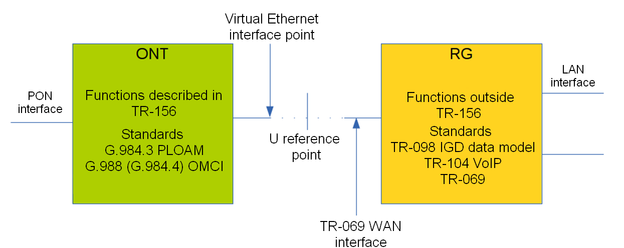
Figure 41 — ONT/RG management domains
Bridged service is a service, which configuration requires the OMCI management domain only, i. e. it can be completely configured with the help of the OMCI protocol in ONT.
Routed service is a service, which configuration requires both the OMCI and RG management domains.
In addition to configuration in terminal, a routed service requires the RG domain to be configured by using one of the following methods:
- Pre-defined configuration — subscriber is provided with an ONT having fixed configuration.
- Local ONT configuration using WEB interface.
- ONT configuration using the TR-069 protocol and auto configuration server (ACS).
Contact ONT vendor for information about RG domain configuration.
ONT is connected to RG using a Virtual Ethernet interface point (VEIP), which corresponds to the TR-069 WAN interface (described in TR-098) on the RG side. VEIP is represented by a virtual port in terminal parameters. The port has the same configuration procedure as Ethernet ports in the ports profile.
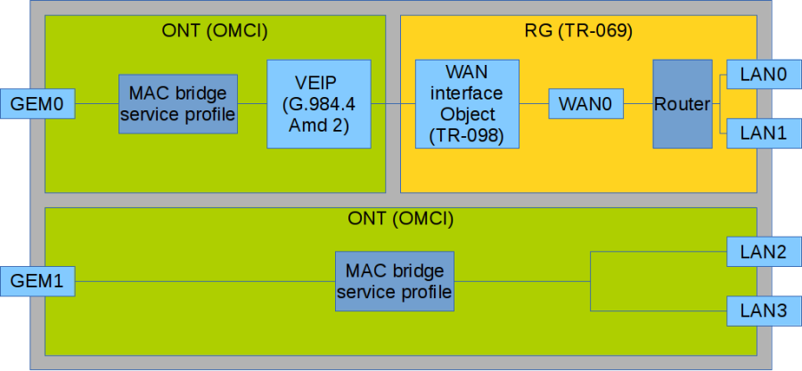
Figure 42 — Services configuration in ONT and RG domains
Figure above shows two services (each with a corresponding GEM port on the ONT side), with one of them being routed and using both the OMCI and RG management domains and the other one being bridged and using only OMCI for configuration. Terminal configuration includes configuration of bridge interfaces (green areas in the figure) and distribution of LAN ports between the management domains.
The bridge parameter of the cross-connect profile is responsible for association of a service with a management domain. Being set, the bridge parameter creates a bridged service (the bridge group parameter is the bridge number in this case). When no bridge is set, a routed service is created (there is only one bridge associated with RG; it has a special bridge number—0).
Mixed configuration
Consider an example of ONT configuration, which simultaneously uses both management domains. Port numbers and the internal structure are shown in Figure 42.
Step 1. Create a VLAN for services on the switch. VLAN configuration is described in detail in VLAN configuration.
LTP-8X(switch)(config)# vlan 20 LTP-8X(switch)(config-vlan)# tagged front-port 0 LTP-8X(switch)(config-vlan)# tagged pon-port 0 – 1 LTP-8X(switch)(config-vlan)# exit LTP-8X(switch)(config)# vlan 30 LTP-8X(switch)(config-vlan)# tagged front-port 0 LTP-8X(switch)(config-vlan)# tagged pon-port 0 – 1
Step 2. Specify 3 as a service model value corresponding to the «VLAN for Service» model by using the gpon olt model command.
LTP-8X# configure terminal LTP-8X(config)# gpon olt model 3
Step 3. Define cross-connect profiles for services.
LTP-8X(config)# profile cross-connect RG-service LTP-8X(config-cross-connect)("RG-service")# exit LTP-8X(config)# profile cross-connect OMCI-serviceStep 4. Define a dba profile. DBA parameters are not important for the purposes of this chapter. Thus, we will not configure these parameters, just use the default values. We will also assign one profile to both services that means that upstream services will operate with one T-CONT. DBA configuration is described in detail in DBA configuration.
LTP-8X(config)# profile dba basic LTP-8X(config-dba)("basic")# exitStep 5. Create ports profile.
LTP-8X(config)# profile ports 2RG-2OMCI LTP-8X(config-ports)("2RG-2OMCI")# exitStep 6. Configure a routed service. Use one VLAN 20 on both the OLT and ONT sides. Specify a routed service by using the no bridge command. Configure a cross-connect profile for the routed service.
LTP-8X(config)# profile cross-connect RG-service LTP-8X(config-cross-connect)("RG-service")# no bridge LTP-8X(config-cross-connect)("RG-service")# type general LTP-8X(config-cross-connect)("RG-service")# tag-mode single-tagged LTP-8X(config-cross-connect)("RG-service")# outer vid 20 LTP-8X(config-cross-connect)("RG-service")# outer cos unused LTP-8X(config-cross-connect)("RG-service")# user vid untagged LTP-8X(config-cross-connect)("RG-service")# mac-table-limit unlimited LTP-8X(config-cross-connect)("RG-service")# priority 0Step 7. Configure a bridged service. Use one VLAN 30 on both the OLT and ONT sides. Specify a bridged service by using the bridge command. Set 1 as the OMCI bridge number. Configure a cross-connect profile for the bridged service.
LTP-8X(config)# profile cross-connect OMCI-service LTP-8X(config-cross-connect)("OMCI-service")# bridge LTP-8X(config-cross-connect)("OMCI-service")# bridge group 1 LTP-8X(config-cross-connect)("OMCI-service")# type general LTP-8X(config-cross-connect)("OMCI-service")# tag-mode single-tagged LTP-8X(config-cross-connect)("OMCI-service")# outer vid 30 LTP-8X(config-cross-connect)("OMCI-service")# outer cos unused LTP-8X(config-cross-connect)("OMCI-service")# user vid untagged LTP-8X(config-cross-connect)("OMCI-service")# mac-table-limit unlimited LTP-8X(config-cross-connect)("OMCI-service")# priority 1You specified different priority queue values for the services. The routed service will have a higher priority than the bridged service as they work with one T-CONT.
Step 8. Configure a ports profile. According to Figure 41, we need to associate the first two LAN ports with the RG management domain, while the other two should be associated with the OMCI domain and bound to bridge 1.
LTP-8X(config)# profile ports 2RG-2OMCI LTP-8X(config-ports)("2RG-2OMCI")# port 0 bridge group 0 LTP-8X(config-ports)("2RG-2OMCI")# port 1 bridge group 0 LTP-8X(config-ports)("2RG-2OMCI")# port 2 bridge group 1 LTP-8X(config-ports)("2RG-2OMCI")# port 3 bridge group 1Step 9. Set the ONT configuration. ONT management is described in detail in Service Models.
LTP-8X(config)# interface ont 0/0
Step 10. Assign the created profiles. Assign the cross-connect RG-service profile to service 0 and the cross-connect OMCI-service profile to service 1.
LTP-8X(config)# serial ELTX10203040 LTP-8X(config)(if-ont-0/0)# service 0 profile cross-connect RG-service LTP-8X(config)(if-ont-0/0)# service 0 profile dba basic LTP-8X(config)(if-ont-0/0)# service 1 profile cross-connect OMCI-service LTP-8X(config)(if-ont-0/0)# service 1 profile dba basic LTP-8X(config)(if-ont-0/0)# profile ports 2RG-2OMCI
Step 11. Use the show interface ont <id> configuration command to check the created configuration.
LTP-8X(config)(if-ont-0/0-1)# do show interface ont 0/0-1 configuration ----------------------------------- [ONT0/0] configuration ----------------------------------- Description: '' Enabled: true Serial: ELTX10203040 ... Service [0]: Profile cross connect: RG-service ONT Profile Cross Connect 1 Profile dba: basic ONT Profile DBA 2 Custom cross connect: disabled Service [1]: Profile cross connect: RG-service ONT Profile Cross Connect 0 Profile dba: basic ONT Profile DBA 2 Custom cross connect: disabled Service [2]: Profile cross connect: SecurityiAlarm ONT Profile Cross Connect 0 Profile dba: OtherServices ONT Profile DBA 4 Custom cross connect: disabled Profile ports: 2RG-2OMCI ONT Profile Ports 1Step 12. Apply changes by the commit command.
LTP-8X(config)(if-ont-0/0)# do commit
As a result, you will have the mixed configuration of the ONT. One of the services is managed completely by the OMCI domain (the bridged service), LAN2 and LAN3 ports on the ONT are connected as bridges. The second service is managed by both OMCI and RG (the routed service; the RG domain can be configured, for instance, through the WEB interface on the ONT). LAN0 and LAN1 ports are connected to RG ONT.
High Speed Internet configuration
Configuration of High Speed Internet (HSI) does not have any peculiarities and can be easily performed as described in Service Models.
Correct operation of IPv6 requires to do the following:
- specify the multicast type when creating a cross-connect profile;
- enable multicast passing on the necessary port (0-4 and/or veip) in the ports profile.
Example of a routed configuration:
LTP-8X(config)# profile cross-connect ipv6
LTP-8X(config-cross-connect)("ipv6")# outer vid 300
LTP-8X(config-cross-connect)("ipv6")# user vid 300
LTP-8X(config-cross-connect)("ipv6")# type multicast
LTP-8X(config-cross-connect)("ipv6")# exit
LTP-8X(config)# profile ports ipv6
LTP-8X(config-ports)("ipv6")# veip multicast
LTP-8X(config-ports)("ipv6")# exit
LTP-8X(config)# exit
LTP-8X# commit
Example of a bridged configuration:
LTP-8X(config)# profile cross-connect ipv6_br
LTP-8X(config-cross-connect)("ipv6_br")# bridge
LTP-8X(config-cross-connect)("ipv6_br")# bridge group 10
LTP-8X(config-cross-connect)("ipv6_br")# outer vid 300
LTP-8X(config-cross-connect)("ipv6_br")# user vid 300
LTP-8X(config-cross-connect)("ipv6_br")# type multicast
LTP-8X(config-cross-connect)("ipv6_br")# exit
LTP-8X(config)# profile ports ipv6_br
LTP-8X(config-ports)("ipv6_br")# port 0 multicast
LTP-8X(config-ports)("ipv6_br")# port 0 bridge group 10
LTP-8X(config-ports)("ipv6_br")# exit
LTP-8X(config)# exit
LTP-8X# commit
Multicast configuration
The chapter describes peculiarities of IPTV service configuration.
Hosts and routers use the Internet Group Management Protocol (IGMP) to support multicasting. It provides all systems of a physical network with relevant information: which hosts are included in groups and which group corresponds to a host.
IGMP snooping is a technique that allows network devices of the channel level (switches) to snoop IGMP requests from hosts to a group router in order to decide whether group traffic transmission to the corresponding interfaces should be started or stopped. When a switch snoops a host's IGMP request for connection to a multicast group, it adds the port the host is connected to into the group (for group traffic retranslation). Having snooped a leave_group request, the switch removes the corresponding port from the group.
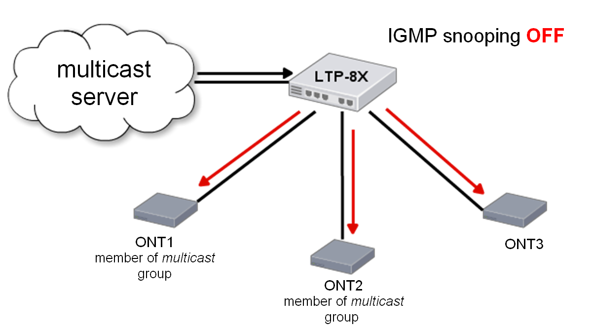
Figure 43 — IGMP snooping is disabled
Figure above shows traffic multicasting regardless of whether an end host needs the traffic or not. When IGMP snooping is enabled, the multicasting situation changes as follows: the switch will analyse all IGMP packets between connected devices and the routers the multicast traffic comes from. When the switch receives a consumer's IGMP request for connection to a multicast group, it adds the port the consumer is connected to into the group. And vice versa, having received a request for leaving a group, the switch removes the corresponding port from the group.
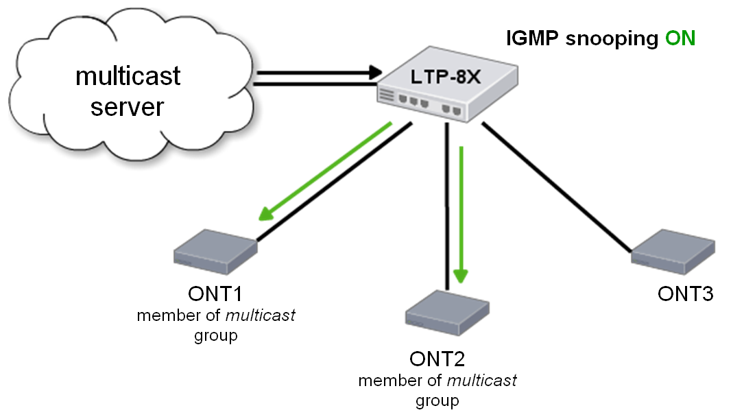
Figure 44 — IGMP snooping is enabled
As you can see from the Figure 44, LTP-8X with enabled IGMP snooping translates multicast traffic only to the hosts, which are members of the IGMP group.
IGMP proxy is an IGMP client and group router at the same time (IGMP router). On the one hand, proxy requests an upstream router for group channels; on the other hand, it receives join/leave requests from hosts and replicates upstream traffic to the corresponding interfaces.
Model 1 Multicast configuration
Consider configuration of a multicast service for Model 1.
An STB, which works in VLAN 14, is connected to an ONT port in this example. Upstream IGMP packets arrive to VLAN 14 though a GEM port and the OLT changes VLAN 14 to subscriber's VLAN 200.
As we have a multicast server in VLAN 98 in our example, we need to configure a proxy on the switch to translate IGMP packets from VLAN 200 to VLAN 98 (for more information, see VLAN configuration). The multicast service comes downstream to the ONT port in VLAN 98 and changes to VLAN 14.
For more information on general configuration principles of data communication channels, see Service Models.
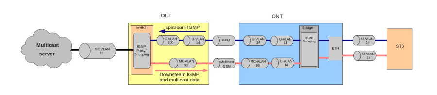
Figure 45 — Model 1 Multicast
Step 1. Specify the ONT serial number in the configuration.
LTP-8X# configure terminal LTP-8X(config)# interface ont 0/0 LTP-8X(config)(if-ont-0/0)# serial ELTX01234567 LTP-8X(config)(if-ont-0/0)# exit
Step 2. Assign a service model.
LTP-8X(config)# gpon olt model 1
Step 3. Create an UsIGMP cross-connect profile to configure the service, which will be used to send IGMP requests upstream. Configure a bridged service and specify the bridge group (it equals 1 in our example) the ONT port will be associated with; specify U-VLAN 14.
LTP-8X(config)# profile cross-connect UsIGMP LTP-8X(config-cross-connect)("UsIGMP")# bridge LTP-8X(config-cross-connect)("UsIGMP")# bridge group 1 LTP-8X(config-cross-connect)("UsIGMP")# user vid 14 LTP-8X(config-cross-connect)("UsIGMP")# do show profile cross-connect UsIGMP Name: 'UsIGMP' Description: 'ONT Profile Cross Connect 1' Model: ont Bridge group: 1 Tag mode: single-tagged Outer vid: 1 Outer cos: unused Inner vid: - U vid: 14 U cos: unused Mac table entry limit: unlimited Type: general IP host index: 0 Priority queue: 0Step 4. Associate the bridge group with an ONT port. To do this, create a ports profile and assign value 1 to the bridge group parameter for the LAN1 port.
LTP-8X(config)# profile ports Ports1 LTP-8X(config-ports)("Ports1")# port 1 bridge group 1Step 5. Enable multicasting and configure VLAN replacement rules for the ONT port.
LTP-8X(config-ports)("Ports1")# port 1 multicast LTP-8X(config-ports)("Ports1")# port 1 igmp downstream vid 14 LTP-8X(config-ports)("Ports1")# port 1 igmp downstream tag-control replace-vid LTP-8X(config-ports)("Ports1")# port 1 igmp upstream vid 14 LTP-8X(config-ports)("Ports1")# port 1 igmp upstream tag-control replace-vidStep 6. You also need to configure VLAN 98 multicasting and specify the group range.
LTP-8X(config-ports)("Ports1")# igmp multicast dynamic-entry 0 vid 98 LTP-8X(config-ports)("Ports1")# igmp multicast dynamic-entry 0 group 224.0.0.0 239.255.255.255 LTP-8X(config-ports)("Ports1")# do show profile ports Ports1 Name: 'Ports1' Description: 'ONT Profile Ports 7' Multicast IP version: IPv4 Igmp settings: Version: IGMP v3 Mode: snooping Immediate leave: false Robustness: 2 Querier ip: 0.0.0.0 Query interval: 125 Query response interval: 100 Last member query interval: 10 Mld settings: Version: MLD v2 Mode: snooping Immediate leave: false Robustness: 2 Querier ipv6: :: Query interval: 125 Query response interval: 100 Last member query interval: 10 ... Port [1]: Speed: auto Duplex: auto Bridge group: 1 Spanning tree for bridge group: false Multicast enable: true Multicast port settings: Upstream igmp vid: 14 Upstream igmp prio: 0 Upstream igmp tag control: replace vid Downstream multicast vid: 14 Downstream multicast prio: 0 Downstream multicast tag control: replace vid Max groups: 0 Max multicast bandwidth: 0 Shaper downstream: Enable: false Commited rate: 1000000 Shaper upstream: Enable: false Commited rate: 1000000 ...Step 7. Assign the created profiles in the ONT. Configure a custom cross-connect profile, specify S-VLAN 200, and apply the configuration.
LTP-8X(config)# interface ont 0/0 LTP-8X(config)(if-ont-0/0)# service 0 profile cross-connect UsIGMP LTP-8X(config)(if-ont-0/0)# profile ports Ports1 LTP-8X(config)(if-ont-0/0)# service 0 custom svid 200 LTP-8X(config)(if-ont-0/0)# do commit
Step 8. Add VLAN 98 and VLAN 200 in the switch view. Enable IGMP snooping.
LTP-8X# switch LTP-8X(switch)# configure terminal LTP-8X(switch)(config)# vlan 200 LTP-8X(switch)(config-vlan)# tagged front-port 0 LTP-8X(switch)(config-vlan)# tagged pon-port 0 – 7 LTP-8X(switch)(config-vlan)# ip igmp snooping enable LTP-8X(switch)(config-vlan)# exit LTP-8X(switch)(config)# vlan 98 LTP-8X(switch)(config-vlan)# tagged front-port 0 LTP-8X(switch)(config-vlan)# tagged pon-port 0 – 7 LTP-8X(switch)(config-vlan)# ip igmp snooping enable LTP-8X(switch)(config-vlan)# exit
Step 9. Configure IGMP proxy for IGMP packets transmission from VLAN 200 to VLAN 98. Apply the configuration.
LTP-8X(switch)(config)# ip igmp proxy report enable LTP-8X(switch)(config)# ip igmp proxy report range 224.0.0.0 239.255.255.255 from 200 to 98 LTP-8X(switch)(config)# ip igmp snooping LTP-8X(switch)(config)# commit
Model 3 Multicast configuration
Consider configuration of a multicast service for Model 3.
The multicast service operates in VLAN 98 in the example below, an STB operating in VLAN 14 is connected to an ONT port. Upstream IGMP packets come to VLAN 14 in the ONT, where VLAN 14 is replaced with the service VLAN 98, and then the data is further transferred upstream through the GEM port. The multicast service comes downstream to the ONT port in VLAN 98 and changes to VLAN 14. For more information on general configuration principles of data communication channels, see Service Models.
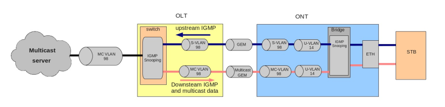
Figure 46 — Model 3 Multicast
Step 1. Specify the ONT serial number in the configuration.
LTP-8X# configure terminal LTP-8X(config)# interface ont 0/0 LTP-8X(config)(if-ont-0/0)# serial ELTX01234567 LTP-8X(config)(if-ont-0/0)# exit
Step 2. Assign a service model.
LTP-8X(config)# gpon olt model 3
Step 3. Create an UsIGMP cross-connect profile to transfer IGMP requests upstream. Configure a bridged service and specify the bridged group (it equals 1 in the example below) the ONT port will be associated with. Specify U-VLAN 14 and S-VLAN 98.
LTP-8X(config)# profile cross-connect UsIGMP LTP-8X(config-cross-connect)("UsIGMP")# bridge LTP-8X(config-cross-connect)("UsIGMP")# bridge group 1 LTP-8X(config-cross-connect)("UsIGMP")# outer vid 98 LTP-8X(config-cross-connect)("UsIGMP")# user vid 14 LTP-8X(config-cross-connect)("UsIGMP")# do show profile cross-connect UsIGMP Name: 'UsIGMP' Description: 'ONT Profile Cross Connect 1' Model: ont Bridge group: 1 Tag mode: single-tagged Outer vid: 98 Outer cos: unused Inner vid: - U vid: 14 U cos: unused Mac table entry limit: unlimited Type: general IP host index: 0 Priority queue: 0Step 4. Associate the bridge group with an ONT port. To do this, create a ports profile and assign value 1 to the bridge group parameter for the LAN1 port.
LTP-8X(config)# profile ports Ports1 LTP-8X(config-ports)("Ports1")# port 1 bridge group 1Step 5. Enable multicasting and configure VLAN replacement rules for the ONT port.
LTP-8X(config-ports)("Ports1")# port 1 multicast LTP-8X(config-ports)("Ports1")# port 1 igmp downstream vid 14 LTP-8X(config-ports)("Ports1")# port 1 igmp downstream tag-control replace-vid LTP-8X(config-ports)("Ports1")# port 1 igmp upstream vid 98 LTP-8X(config-ports)("Ports1")# port 1 igmp upstream tag-control replace-vidStep 6. You also need to configure VLAN 98 multicasting and specify the group range.
LTP-8X(config-ports)("Ports1")# igmp multicast dynamic-entry 0 vid 98 LTP-8X(config-ports)("Ports1")# igmp multicast dynamic-entry 0 group 224.0.0.0 239.255.255.255 LTP-8X(config-ports)("Ports1")# do show profile ports Ports1 ... Igmp settings: ... Multicast dynamic entry [0]: Vlan id: 98 First group ip: 224.0.0.1 Last group ip: 239.255.255.255 ... Port [1]: Speed: auto Duplex: auto Bridge group: 0 Spanning tree for bridge group: false Multicast enable: false Multicast port settings: Upstream igmp vid: 98 Upstream igmp prio: 0 Upstream igmp tag control: replace-vid Downstream multicast vid: 14 Downstream multicast prio: 0 Downstream multicast tag control: replace-vid Max groups: 0 Max multicast bandwidth: 0 Shaper downstream: Enable: false Commited rate: 1000000 Shaper upstream: Enable: false Commited rate: 1000000 ...Step 7. Assign the created profiles in the ONT and apply the configuration.
LTP-8X(config)# interface ont 0/0 LTP-8X(config)(if-ont-0/0)# service 0 profile cross-connect UsIGMP LTP-8X(config)(if-ont-0/0)# profile ports Ports1 LTP-8X(config)(if-ont-0/0)# do commit
Step 8. Add VLAN 98 in the switch view and enable IGMP snooping.
LTP-8X# switch LTP-8X(switch)# configure terminal LTP-8X(switch)(config)# vlan 98 LTP-8X(switch)(config-vlan)# tagged front-port 0 LTP-8X(switch)(config-vlan)# tagged pon-port 0 – 7 LTP-8X(switch)(config-vlan)# ip igmp snooping enable LTP-8X(switch)(config-vlan)# exit LTP-8X(switch)(config)# ip igmp snooping LTP-8X(switch)(config)# commit
IPv6 Multicast configuration
IPv6 multicast is configured the same way as shown above. However, there are some differences in configuration.
Step 1. Change the IP protocol to IPv6, Configure VLAN 98 multicast, and specify the group range.
LTP-8X(config-ports)("Ports1")# multicast ip version ipv6 LTP-8X(config-ports)("Ports1")# mld multicast dynamic-entry 0 vid 98 LTP-8X(config-ports)("Ports1")# mld multicast dynamic-entry 0 group ff15:0::1 ff15:0::ffff LTP-8X(config-ports)("Ports1")# do show profile ports Ports1 Name: 'Ports1' Description: 'ONT Profile Ports 7' Multicast IP version: IPv6 Igmp settings: Version: IGMP v3 Mode: snooping Immediate leave: false Robustness: 2 Querier ip: 0.0.0.0 Query interval: 125 Query response interval: 100 Last member query interval: 10 Mld settings: Version: MLD v2 Mode: snooping Immediate leave: false Robustness: 2 Querier ipv6: :: Query interval: 30 Query response interval: 100 Last member query interval: 10 Multicast dynamic entry v6 [0]:Vlan id: 98 First group ip: ff15:0::1 Last group ip: ff15:0::ffff Preview length: 55 Preview repeat time: 60 Preview repeat count: 0 Preview reset time: 3 ... Port [1]: Speed: auto Duplex: auto Bridge group: 1 Spanning tree for bridge group: false Multicast enable: true Multicast port settings: Upstream igmp vid: 14 Upstream igmp prio: 0 Upstream igmp tag control: replace vid Downstream multicast vid: 14 Downstream multicast prio: 0 Downstream multicast tag control: replace vid Max groups: 0 Max multicast bandwidth: 0 Shaper downstream: Enable: false Commited rate: 1000000 Shaper upstream: Enable: false Commited rate: 1000000Step 2. Add VLAN 98 in the switch view and enable MLD snooping.
MLD snooping is not supported for Model 1.
VoIP configuration
The chapter describes peculiarities of VoIP service configuration. The terminal supports several methods of VoIP configuration:
- VoIP Configuration in OMCI management domain;
- VoIP configuration in the RG management domain.
A method is chosen based on service model and ONT functionality.
VoIP Configuration in OMCI management domain
VoIP is a special bridged service. It has all general properties of a bridged service. Operator's actions required for services configuration are described in detail in ONT configuration.
As opposed to other bridge services, VoIP requires the iphost type in the cross-connect profile to terminate traffic in internal virtual IP interface. That also requires the Iphost eid parameter to be specified. As a rule, it should equal 1. Contact your ONT vendor for information about the Iphost eid value for the VoIP.
Step 1. Configure a cross-connect profile to be used as VoIP.
LTP-8X(config)# profile cross-connect VoIP LTP-8X(config-cross-connect)("VoIP")# bridge LTP-8X(config-cross-connect)("VoIP")# type iphost LTP-8X(config-cross-connect)("VoIP")# bridge group 2 LTP-8X(config-cross-connect)("VoIP")# iphost eid 1Step 2. Check the changes made.
LTP-8X(config-cross-connect)("VoIP")# do show profile cross-connect VoIP ... Type: iphost IP host index: 1 Priority queue: 0Step 3. Apply the changes by using the commit command.
LTP-8X(config-cross-connect)("VoIP")# do commit
VoIP configuration in RG management domain
In case the VoIP client is located after the U point (i. e. in the RG management domain), the VoIP service has the same configuration procedure as all other routed services. The procedure is described in detail in ONT configuration. All the general steps of service configuration are applied to VoIP as well.
Configuration of management via TR-069
This chapter describes configuration of a data communication channel for the CPE management service via the TR-069 protocol.
An ONT management channel can be established in one of the two modes: Inband and OutOfBand. Inband is the preferred mode as it is simpler. Contact your ONT vendor for information about operation capabilities of both modes.
ONT management via TR-069 is a special service. All general steps of service configuration apply to TR-069 management. Operator's actions required for services configuration are described in detail in ONT configuration.
As opposed to other services, the management service requires the management type in the cross-connect profile. You also need to specify the Iphost eid parameter. As a rule, it should equal 0.
Configuration of a TR-069 Inband management
This mode is characterised by its simple implementation. Management traffic goes through the same bridge as user traffic. Figure below shows a part of the OMCI layout. Arrows show the traffic flow.
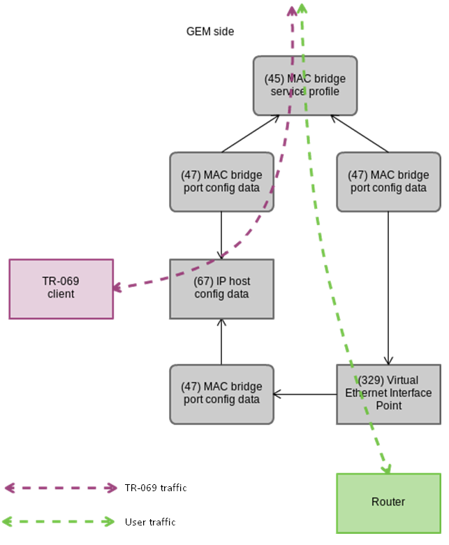
Figure 47 — TR-069 Inband management channel
Step 1. Set the management type in the cross-connect profile.
LTP-8X(config)# profile cross-connect TR069 LTP-8X(config-cross-connect)("TR069")# type managementStep 2. Set the ont-rg model in the cross-connect profile.
LTP-8X(config-cross-connect)("TR069")# no bridgeStep 3. Set the IP Host identifier to 0.
LTP-8X(config-cross-connect)("TR069")# iphost eid 0Step 4. Check the changes made with the show profile cross-connect command.
LTP-8X(config-cross-connect)("TR069")# do show profile cross-connect TR069 Name: 'TR069' Description: 'ONT Profile Cross Connect 1' Model: ont-rg Bridge group: - Tag mode: single-tagged Outer vid: 1 Outer cos: unused Inner vid: - U vid: untagged U cos: unused Mac table entry limit: unlimited Type: management IP host index: 0Step 5. Apply the changes by using the commit command.
LTP-8X(config-cross-connect)("TR069")# do commit
Configuration of a TR-069 OOB management channel
Not all ONT vendors support creation of Inband management channels via TR-069. To solve this, a capability to create an OutOfBand management channel was developed as an alternative. The main peculiarity of the mode is the use of a separate bridge for management. See a part of the OMCI layout below. Arrows show the traffic flow.
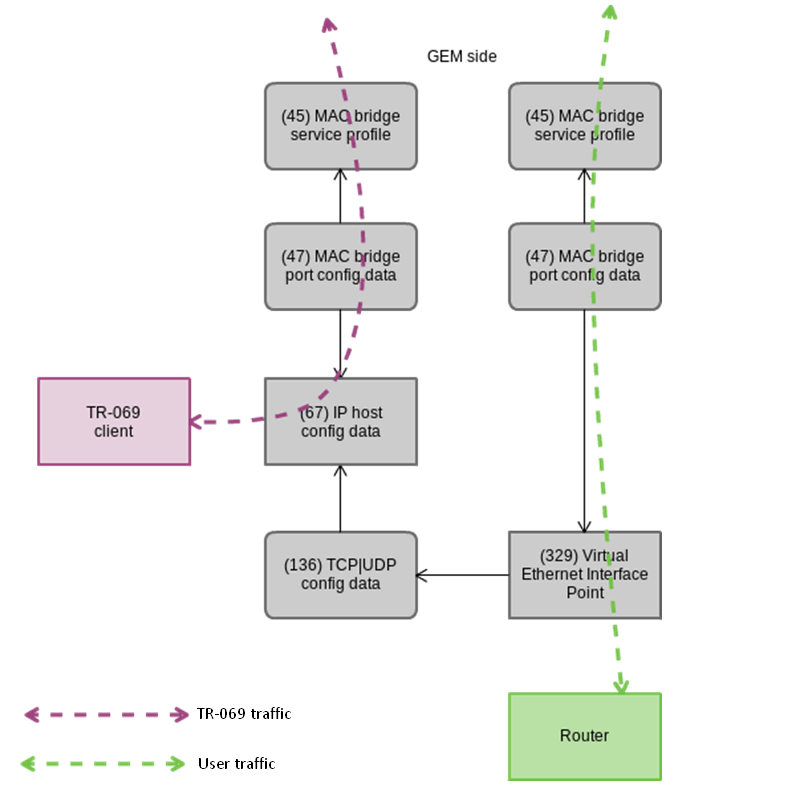
Figure 48 — TR-069 OutOfband management channel
Step 1. Set the management type in the cross-connect profile.
LTP-8X(config)# profile cross-connect TR069 LTP-8X(config-cross-connect)("TR069")# type managementStep 2. Set the ont model in the cross-connect profile. Specify a separate bridge-group.
LTP-8X(config-cross-connect)("TR069")# bridge LTP-8X(config-cross-connect)("TR069")# bridge group 20Step 3. Set the IP Host identifier to 0.
LTP-8X(config-cross-connect)("TR069")# iphost eid 0Step 4. Check the changes by using the show profile cross-connect command.
LTP-8X(config-cross-connect)("TR069")# do show profile cross-connect TR069 Name: ’TR069’ Description: ’ONT Profile Cross Connect 1’ Model: ont Bridge group: 20 Tag mode: single-tagged Outer vid: 1 Outer cos: unused Inner vid: - U vid: untagged U cos: unused Mac table entry limit: unlimited Type: management Iphost eid: 0 Priority queue: 0 LTP-8X(pon/profiles-ont/cross-connect-6)Step 5. Apply the changes by using the commit command.
LTP-8X(config-cross-connect)("TR069")# do commit
TR-069 client parameters configuration
To configure TR-069 client parameters, use the management profile.
LTP-8X# show profile management management-00
Name: 'management-00'
Description: 'ONT Profile Management 0'
Enable omci configuration: true
Url: ''
Username: ''
Password: ''
In case when the DHCP server transmits the TR-069 parameters via option 43, there is no need to transfer them via OMCI. Disable this phase with the no omci-configuration command.
Otherwise, specify TR-069 client parameters explicitly.
Step 1. Enable TR-069 configuration.
LTP-8X(config)# profile management management-00 LTP-8X(config-management)("management-00")# omci-configurationStep 2. Specify the connection parameters.
LTP-8X(config-management)("management-00")# url http://acs.tele.com:9595/acs LTP-8X(config-management)("management-00")# username acs LTP-8X(config-management)("management-00")# password acsacsStep 3. Check the changes made.
LTP-8X(config-management)("management-00")# do show profile management management-00 Name: 'management-00' Description: 'ONT Profile Management 0' Enable omci configuration: true Url: 'http://acs.tele.com:9595/acs' Username: 'acs' Password: 'acsacs'Step 4. Apply the changes by using the commit command.
LTP-8X(config-management)("management-00")# do commit
ONT configuration templates
It is not always convenient, especially for large-scale operators, to build ONT configuration from separate profiles for each subscriber. This process is painstaking and risky in a certain sense, as it is highly prone to operator error.
As a rule, such companies employ at least one service plan with pre-defined ONT profiles. This section describes ONT templates, an effective solution to simplify the work of subscriber service specialists.
The essence of configuration templates is simple. Network administrator prepares required quantity of templates for the quantity of service plans. Configuration template contains detailed profile list and a set of ONT parameters. Subscriber service specialist or OSS/BSS system assigns the template to an ONT and identifies additional configuration parameters if necessary. As a rule, configuration assignment is performed in "one click" or by using one command.
Preparing ONT configuration template
Step 1. Define an ONT configuration template.
LTP-8X(config)# template HSI-100-CaTV LTP-8X(ont-template)("HSI-100-CaTV")#Step 2. Set the ONT configuration. Template configuration does not have any peculiarities and exactly follows the ONT configuration process described in ONT configuration.
LTP-8X(ont-template)("HSI-100-CaTV")# service 0 profile dba AllServices LTP-8X(ont-template)("HSI-100-CaTV")# service 0 profile cross-connect Service1 LTP-8X(ont-template)("HSI-100-CaTV")# service 1 profile dba AllServices LTP-8X(ont-template)("HSI-100-CaTV")# service 1 profile cross-connect Service2 LTP-8X(ont-template)("HSI-100-CaTV")# profile ports Ports1Step 3. Disable all configuration parameters that should be specified explicitly for the ONT with the undefine command, if necessary.
LTP-8X(ont-template)("HSI-100-CaTV")# undefine rf-port-stateStep 4. Apply the changes.
LTP-8X(ont-template)("HSI-100-CaTV")# do commit
ONT configuration template assignment
Step 1. Switch to the ONT view. You can use a range of ONT IDs for group operations if necessary.
LTP-8X(config)# interface ont 0/0-10 LTP-8X(config)(if-ont-0/0-10)#
Step 2. Assign an ONT configuration template by using the template command.
LTP-8X(config)(if-ont-0/0-10)# template HSI-100-CaTV
Step 3. Define individual ONT parameters not specified in the template if necessary.
LTP-8X(config)(if-ont-0/0-10)# rf-port-state enabled
Step 4. Apply the changes.
LTP-8X(config)(if-ont-0/0-10)# do commit
ONT configuration preview with templates
You can view the ONT configuration using the same command: show interface ont <id> configuration. You can distinguish the template parameters from the general ones by [T](Template) markers. In this example, Rf port state is the only general parameter.
LTP-8X(config)(if-ont-0/0-10)# do show interface ont 0/0 configuration
-----------------------------------
[ONT0/0] configuration
-----------------------------------
Description: ''
Enabled: true
Serial: ELTX5C00008C
Password: ‘0000000000'
[T] Fec up: false
[T] Easy mode: false
[T] Downstream broadcast: true
[T] Downstream broadcast filter: true
[T] Ber interval: none
[T] Ber update period: 60
Rf port state: disabled
[T] Omci error tolerant: false
Service [0]:
[T] Profile cross connect: Service1 NT Profile Cross Connect 1
[T] Profile dba: dba-00 ONT Profile DBA 0
Custom cross connect: disabled
Service [1]:
[T] Profile cross connect: Service2 NT Profile Cross Connect 2
[T] Profile dba: dba-00 ONT Profile DBA 0
Custom cross connect: disabled
[T] Profile shaping: shaping-00 ONT Profile Shaping 0
[T] Profile ports: ports-00 ONT Profile Ports 0
[T] Profile management: unassigned
Template: test ONT Template 1
ONT ports management
This chapter describes Ethernet ports management via OMCI.
The ability to enable/disable Ethernet ports on connected ONT was implemented, as well as ability to manage and control Poe on ONT as power supply.
In case of PoE support from ONT side, it is possible to control ports:
- enabling/disabling PoE on ports;
- power classes control;
- priority configuration.
All these attributes are transmitted via OMCI (ITU-T G.988 ME 11 "PPTP Ethernet UNI").
Ethernet ports management on ONT
Ethernet ports management on ONT means enabling/disabling the port and performed by [no] port <port number> shutdown command, where <port number> is the number of "0-3" port.
Step 1. To disable Ethernet port, do the following commands.
LTP-8X(config)(if-ont-0/0)# port 0 shutdown LTP-8X(config)(if-ont-0/0)# do commit
Step 2. Make sure that changes has been applied, to do that, run the command.
LTP-8X(config)(if-ont-0/0)# do show interface ont 0/0 configuration ... Ports: Port [0]: shutdown: true PoE: Enable: false Pse class control: 0 Power priority: high Port [1]: shutdown: false PoE: Enable: true Pse class control: 0 Power priority: high ...
Step 3. To enable Ethernet port, do the following commands.
LTP-8X(config)(if-ont-0/0)# no port 0 shutdown LTP-8X(config)(if-ont-0/0)# do commit
PoE management on ONT ports
PoE management on ONT ports is performed using port <port number> poe enable pseclass-control <class> power-priority <level> command, where
- <port number> –"0–3" port number,
- <class> – "0–5" power class,
- <level> – "critical/high/low" priority level.
Enabling PoE on ONT ports
To enable PoE on ONT ports, do the following:
LTP-8X(config)(if-ont-0/0)# port 0 poe enable LTP-8X(config)(if-ont-0/0)# do commit
Power class control
This attribute can be used to set specific limits on the power class.
Valid values for this attribute:
- 0 – power is on at the default level for this port;
- 1 – power supply is permitted at power class level 0;
- 2 – power supply is permitted at power class level 1;
- 3 – power supply is permitted at power class level 2;
- 4 – power supply is permitted at power class level 3;
- 5 – power supply is permitted at power class level 4;
To change PoE on ONT ports, do the following:
LTP-8X(config)(if-ont-0/0)# port 0 poe pse-class-control 0 LTP-8X(config)(if-ont-0/0)# do commit
PoE priority settings
This attribute controls port priority in terms of the power management algorithm. Priority set by this attribute can be used by control mechanism which prevents overcurrent situations by disabling ports with lower power priority.
Valid values for this attribute:
- critical;
- high;
- low.
To change PoE priority on ONT ports, do the following:
LTP-8X(config)(if-ont-0/0)# port 0 poe power-priority low LTP-8X(config)(if-ont-0/0)# do commit
Terminal monitoring
General information
Information on current terminal firmware version
To view information on the current version of terminal firmware, use the show version command.
LTP-8X# show version Eltex LTP-8X:rev.C software version 3.40.0 build ХХХХ on ХХ.ХХ.2020 ХХ:ХХ
Terminal information preview
To view information about the terminal, use the show system environment command.
LTP-8X# show system environment
System information:
CPU load average (1m, 5m, 15m): 4.23 2.89 2.53
Free RAM/Total RAM (Mbytes): 260/495
Temperature (sensor1/sensor2): 35C/50C
Reset button: disabled
Fan configured speed, %: 15
Fan minimum speed, %: 15
Fan speed levels, %: 16 27 39 51 64 76 88 100
Fan state (fan0/fan1): 4620rpm 4620rpm
PLD FW version: 14
TYPE: LTP-8X:rev.C
HW_revision: 1v4
SN: GP2B000304
MAC: A8:F9:4B:8B:79:D0
Power supply information:
Module 1: PM160 220/12 1vX
Type: Alternate current(AC)
Intact: 1
Module 2: PM160 220/12 1vX
Type: Alternate current(AC)
Intact: 1
Table 30 — Terminal parameters
Parameter | Description |
|---|---|
CPU load average | Average processor load |
Free RAM/Total RAM | Free/total RAM |
Temperature | Temperature from sensors 1 and 2 |
Reset button | The action depends on the reset button configuration |
Fan configured speed | Set fan rotation speed |
Fan minimum speed | Minimum fan rotation speed |
Fan speed levels | Set fan rotation speed for each level |
Fan state | Fans state and rpm value |
PLD FW Version | PLD firmware version |
Power supply information | Information about installed power modules |
Information on terminal operation time
To view terminal operating time, use the show uptime command.
LTP-8X# show uptime up 7 days, 20:11
Network connection check
To check network connection, use the ping command. As a parameter, pass the IP address of the node to be checked.
LTP-8X# ping 192.168.1.254 PING 192.168.1.254 (192.168.1.254): 56 data bytes 64 bytes from 192.168.1.254: seq=0 ttl=64 time=0.422 ms 64 bytes from 192.168.1.254: seq=1 ttl=64 time=0.426 ms 64 bytes from 192.168.1.254: seq=2 ttl=64 time=0.360 ms 64 bytes from 192.168.1.254: seq=3 ttl=64 time=0.397 ms 64 bytes from 192.168.1.254: seq=4 ttl=64 time=0.404 ms --- 192.168.1.254 ping statistics --- 5 packets transmitted, 5 packets received, 0% packet loss round-trip min/avg/max = 0.360/0.401/0.426 ms
Terminal operation log
Use show log command to view log files.
LTP-8X# show log
## Name Size in bytes Date of last modification
1 ltp 994625 Thu Aug 31 13:51:20 2017
2 ltp.1.gz 41784 Thu Aug 29 12:42:25 2017
3 ltp.2.gz 59829 Thu Aug 29 00:13:10 2017
Total files: 3
AntonLTP-8X#
Use the show log buffer command to view a local terminal operation log buffer.
LTP-8X# show log buffer ... Jan 1 00:00:49 LTP-8X pmchal: notice: [OLT] OLT reset successfully Jan 1 00:01:05 LTP-8X pmchal: notice: [PPPOEIA] PPPoE IA initialized successfully Jan 1 00:01:05 LTP-8X pmchal: notice: [DHCPRA] DHCP RA initialized successfully Jan 1 00:01:11 LTP-8X pmchal: notice: [OLT] OLT initialized successfully Jan 1 00:01:11 LTP-8X pmchal: notice: [OLT] OLT0 FW version 2.3.37.1008 Jan 1 00:01:11 LTP-8X pmchal: notice: [OLT] OLT0 FW is up to date Jan 1 00:01:11 LTP-8X pmchal: notice: [OLT] OLT1 FW version 2.3.37.1008 Jan 1 00:01:11 LTP-8X pmchal: notice: [OLT] OLT1 FW is up to date ...
The log messages can be filtered. To do this, use the show log buffer grep command. The command takes a string as a parameter that is used for search in the log. Only the messages containing the string will be displayed on the screen.
LTP-8X# show log buffer grep pmchal
If console output or output to CLI sessions is configured for log messages, the messages will be output to these devices automatically as soon as they are generated. User does not need to perform any additional operations.
When a remote syslog server is used, use the log display tools provided by the SYSLOG server. Enter show log <filename> command to view the files.
LTP-8X# show log ltp.1.gz
Active alarms log
To view the active alarms log, use the show alarms command. Pass an event type as a parameter (see Table 14) and/or their severity (see Table 15). You can view all active alarms by using the show alarm active all command.
LTP-8X# show alarm active all
Active alarms (1):
## Type Severity Description
0 Fan Critical FAN1 0 rpm
LTP-8X#
GPON monitoring
GPON OLT state
Step 1. To view the state of GPON OLT, use the show gpon olt state command.
LTP-8X# show gpon olt state Device count: 2 Gpon-ports per device: 4 Driver version: 1.2.119 Device 0: Firmware version: 2.3.37.1036 Hardware version: 5211.2 Device 1: Firmware version: 2.3.37.1036 Hardware version: 5211.2 LTP-8X#
GPON OLT parameters are listed and described in table below.
Table 31 — GPON OLT parameters
Parameter | Description |
|---|---|
Device count | The number of OLT chips |
Gpon-ports per device | The number of channels in one OLT chip |
Firmware version | OLT chip firmware version |
Hardware version | OLT chip hardware version |
GPON interface state
Step 1. To view the state of GPON interfaces, use the show interface gpon-port <ID> state command.
LTP-8X# show interface gpon-port 0-3 state Reading: .... Gpon-ports status information: Gpon-port: 0 1 2 3 State: OK OK OK OK ONT count: 1 0 29 0 Force-mode: enabled disabled disabled disabled ONT autofind: enabled enabled enabled enabled SFP vendor: Ligent n/a Ligent n/a SFP product number: LTE3680M-BC n/a LTE3680M-BC n/a SFP vendor revision: 1.0 n/a 1.0 n/a SFP temperature [C]: 71 n/a 74 n/a SFP voltage [V]: 3.19 n/a 3.23 n/a SFP tx bias current [mA]: 17.61 n/a 21.16 n/a SFP tx power [dBm]: 3.54 n/a 3.75 n/aTable 32 — GPON interface parameters
Parameter
Description
Gpon-port
Channel number
State
Channel state
ONT count
The number of ONTs in the channel
SFP vendor
SFP vendor
SFP product number
SFP model
SFP vendor revision
SFP revision
SFP temperature
SFP temperature in Celsius degrees
SFP voltage
SFP voltage in Volts
SFP tx bias current
Bias current in mA
SFP tx power
Transmission power in dBm
Table 33 — GPON interface states
Value
Description
INITED
The channel is initialised
CFGINPROGRESS
The channel configuration is in progress
CFGFAILED
The channel configuration completed with error
OK
The channel is in operation
FAILED
The channel is out of operation
DISABLED
The channel is disabled
Step 2. To view the state of only one GPON interface, use the show interface gpon-port <ID> state command. That means you need to specify the interface number.
LTP-8X# show interface gpon-port 0 state Reading: . Gpon-port status information: Gpon-port: 0 State: OK ONT count: 1 Force-mode: enabled ONT autofind: enabled SFP vendor: Ligent SFP product number: LTE3680M-BC SFP vendor revision: 1.0 SFP temperature [C]: 71 SFP voltage [V]: 3.19 SFP tx bias current [mA]: 17.61 SFP tx power [dBm]: 3.54
MAC table preview
Step 1. To view the table of MAC addresses on the fourth port of the GPON interface, use the show mac interface gpon-port 4 command.
LTP-8X# show mac interface gpon-port 4 ## ONT Serial ONT ID GPON-port GEM UVID CVID SVID MAC 1 ELTX06000022 74 4 912 1214 A8:F9:4B:40:05:1B 2 ELTX06000060 86 4 1008 1214 A8:F9:4B:40:07:0B 3 ELTX06001B70 88 4 1024 1214 A8:F9:4B:41:1F:9B Total records: 3 of 3
Statistics for GPON interfaces
Step 1. To view statistics on GPON interfaces, use the show interface gpon-port <ID> counters command. ID means the GPON interface number. You can specify several interfaces at once.
LTP-8X# show interface gpon-port 0-3 counters ## Downstream counters for channels: 0 1 2 3 2 RX DS octets 128548 128548 128548 128548 3 RX DS packets 1867 1867 1867 1867 5 RX DS octets for channel 128548 18556 18556 18556 6 RX DS packets for channel 1867 202 202 202 8 TX DS octets 128548 18556 18556 18556 9 TX DS packets 1867 202 202 202 11 DS octets 28870 17596 17596 17596 12 DS packets 334 187 187 187 13 DS unicast packets 0 0 0 0 14 DS multicast packets 334 187 187 187 15 DS broadcast packets 0 0 0 0 16 DS packet dropped 1533 15 15 15 ## Upstream counters for channels: 0 1 2 3 2 TX US octets 0 0 0 0 3 TX US packets 0 0 0 0 5 US octets 0 0 0 0 6 US packets 0 0 0 0 7 US unicast packets 0 0 0 0 8 US multicast packets 0 0 0 0 9 US broadcast packets 0 0 0 0 10 US packed dropped 0 0 0 0 11 Packet dropped (CRC) 0 0 0 0 13 TX US octets reassembly 0 0 0 0 14 TX US packets reassembly 0 0 0 0
Statistics for OLT Ethernet interfaces
Step 1. To view statistics on Ethernet interfaces of the OLT (connected to the terminal switch), use the show interface gpon-port <ID> counters v-interface command.
LTP-8X# show interface gpon-port 0 counters v-interface ## Downstream counters for channels: 0 1 RX Alignment errors 0 2 RX Pause frames 0 3 RX CRC-32 errors 0 4 RX Oversize errors 0 5 RX Bad FCS 0 6 RX Too long frames 0 7 RX Undersize errors 0 8 RX Range errors 0 9 RX Ok frames 3965150 10 RX total frames 3965150 11 RX 64 octets frames 314 12 RX 65-127 octets frames 3964297 13 RX 128-255 octets frames 59 14 RX 256-511 octets frames 480 15 RX 512-1023 octets frames 0 16 RX 1024-1518 octets frames 0 17 RX 1519-MAX octets frames 0 18 RX Total unicast packets 83 19 RX Total multicast packets 3679683 20 RX Total broadcast packets 285384 22 RX Total octets 269746879 24 RX Ok octets 269746879 25 RX FIFO overflow errors 0 26 RX Bad FCS and <64 octets 0 27 RX Frame errors 0 ## Upstream counters for channels: 0 1 TX frames without errors 0 2 TX valid pause frames 0 3 TX frames with errors 0 4 TX good unicast packets 0 5 TX good multicast packets 0 6 TX good broadcast packets 0 8 TX octets 0
Multicast statistics
Step 1. To view statistics on MC streams, use the show interface gpon-port <ID> igmp groups command. As a parameter, pass the channel number or a range of channels.
LTP-8X# show interface gpon-port 0-7 igmp groups All IGMP groups (104): ## GPON-port Serial Multicast address Start Stop 1 4 ELTX66000074 239.1.128.43 2017.11.21 09:58:02 2017.11.21 11:25:21 2 4 ELTX67000050 239.1.128.43 2017.11.21 09:58:02 2017.11.21 11:25:21 3 4 ELTX6700007C 239.1.128.43 2017.11.21 09:58:02 ---
ONT monitoring
ONT configurations list
Step 1. To view active ONT configurations, use the show interface ont <ID> configured command. As an ID, pass the GPON port number or a range of numbers.
LTP-8X# show interface gpon-port ont 2 configured ----------------------------------- GPON-port 0 ONT configured list ----------------------------------- ## Serial ONT ID GPON-PORT Status RSSI[dBm] Version EquipmentID Description 1 454C54581A000021 0 2 OFFLINE n/a n/a n/a 2 444C4E4B8713F000 1 2 OFFLINE n/a n/a n/a 3 48575443904D6425 2 2 OFFLINE n/a n/a n/a 4 454C545806000024 3 2 OFFLINE n/a n/a n/a 5 454C54585D000048 4 2 OFFLINE n/a n/a n/a 6 454C54585F0009E8 10 2 OK -8.16 3.22.0.1669 NTU-2V Total ONT count: 6
List of empty ONT configurations
Step 1. To view empty ONT configurations (vacant ONT IDs), use the show interface ont <ID> unconfigured command.
LTP-8X# show interface ont 0-7 unconfigured GPON-port 0 ONT unconfigured list: 3,5-49,51-127 GPON-port 1 ONT unconfigured list: 0-127 GPON-port 2 ONT unconfigured list: 5-9, 11-127 GPON-port 3 ONT unconfigured list: 0-127 GPON-port 4 ONT unconfigured list: 32-127 GPON-port 5 ONT unconfigured list: 0-127 GPON-port 6 ONT unconfigured list: 0,2-127 GPON-port 7 ONT unconfigured list: 3,22,35127 Total ONT count: 947
List of connected ONTs
Step 1. To view the list of online ONTs, use the following command: show interface ont <ID> online. As an argument, specify the GPON interface number or a range of numbers.
LTP-8X# show interface ont 0 online ----------------------------------- GPON-port 0 ONT online list ----------------------------------- ## Serial ONT ID GPON-PORT Status RSSI[dBm] Version EquipmentID 1 ELTX5C00008C 3 0 OK -23.19 3.50.2.1157 NTU-RG-1402G-W 2 ELTX1A00001A 2 0 OK -24.44 3.21.1.1928 NTP-RG-1402G-W:rev.C GPON-port 1 has no online ONTs GPON-port 2 has no online ONTs GPON-port 3 has no online ONTs
GPON-port 4 has no online ONTs GPON-port 5 has no online ONTs GPON-port 6 has no online ONTs GPON-port 7 has no online ONTs Total ONT count: 2
Table 34 — ONT status description
ONT status
Description
UNACTIVATED
ONT has no configurations
ALLOCATED
ONT detected
AUTHINPROGRESS
ONT authentication is in progress
AUTHFAILED
Authentication failed
AUTHOK
Authentication successfully completed
PRECONFIG
Preparing ONT for configuration
CFGINPROGRESS
ONT configuration is in progress
CFGFAILED
Configuration failed
OK
ONT is in operation
BLOCKED
ONT is blocked
MIBRESET
ONT MIB reset
FAILED
ONT has a critical failure
FWUPDATING
ONT firmware update is in progress
DISABLED
ONT is disabled (technically blocked)
## Serial ONT ID GPON-PORT Status RSSI[dBm] Version EquipmentID 1 ELTX5C00008C 3 0 OK -23.19 3.50.2.1157 NTU-RG-1402G-W 2 ELTX1A00001A 2 0 OK -24.44 3.21.1.1928 NTP-RG-1402G-W:rev.C GPON-port 1 has no online ONTs GPON-port 2 has no online ONTs GPON-port 3 has no online ONTs
List of disconnected ONTs
Step 1. To view the list of offline ONTs, use the show interface ont <ID> offline command. As an argument, specify the GPON interface number or a range of numbers.
LTP-8X# show interface ont 0-7 offline ----------------------------------- GPON-port 0 ONT offline list ----------------------------------- ## Serial ONT ID GPON-port Description 1 454C54585C0908B4 0 0 GPON-port 1 has no offline ONTs GPON-port 2 has no offline ONTsGPON-port 3 has no offline ONTs GPON-port 4 has no offline ONTs GPON-port 5 has no offline ONTs GPON-port 6 has no offline ONTs GPON-port 7 has no offline ONTs Total ONT count: 1
ONT statistics
To view ONT statistics, use the show interface ont <ID> counters <type> command. As an argument, pass the ONT ID and the type of requested statistics (see Table 35).
LTP-8X# show interface ont 4/0 counters gem-port-nctp-performance-monitoring
-----------------------------------
[ONT4/0] counters
-----------------------------------
## Downstream counters for cross-connects: 0 ... 7 MC BC
1 Finished intervals 202 ... --- --- ---
2 Received GEM frames 54 ... --- --- ---
4 Received payload bytes 11576 ... --- --- ---
## Upstream counters for cross-connects: 0 ... 7 MC BC
1 Finished intervals 202 ... --- --- ---
2 Transmitted GEM frames 54 ... --- --- ---
4 Transmitted payload bytes 10448 ... --- --- ---
Table 35 — ONT statistics types
Statistics type |
|---|
gem-port-performance-monitoring |
gem-port-nctp-performance-monitoring |
ethernet-performance-monitoring-history-data |
ethernet-performance-monitoring-history-data2 |
ethernet-performance-monitoring-history-data3 |
gal-ethernet-performance-monitoring-history-data |
fec-performance-monitoring-history-data |
ethernet-frame-extended-performance-monitoring |
multicast-subscriber-monitor |
ONT bit error rate
Bit error rate (BER) is the rate of errors in data transmission.
To view BER on reception at the ONT, use the show interface gpon-port <id> downstream-ber command. As an argument, pass the number of the GPON interface.
LTP-8X# show interface gpon-port 0 downstream-ber ----------------------------------- GPON-port 0 BER table ----------------------------------- ## Ch/ Id Errors Intervals BER Interval BER 1 0/ 2 0 0 100000 0 2 0/ 3 0 0 100000 0
Viewing the status of ONT ports
To view the status of the ONT ports, run the show interface ont <ID> ports command. Pass the ONT identifier as an argument.
LTP-8X# show interface ont 0/0 ports
-----------------------------------
[ONT0/0] ports state
-----------------------------------
UNI ## 0 1
Link: up up
Speed: 100M 100M
Duplex: full full
PoE:
State: enable enable
Power detection status: Delivering power Delivering power
Power classification status: Class 3 Class 3
PsE class control: Default Default
Power priority: high high
Consumption: 1600 mW 1600 mW
Table 36 — Description of PSE statuses
PSE status | Description |
|---|---|
Disabled | PoE connectivity on the port is disabled |
Searching | PoE connectivity on the port is enabled, waiting for device connection |
Delivering power | PoE device is connected, power is supplied |
Test mode | Test mode |
Fault | Error is detected |
Specific fault | Implementation error is detected |
System environment configuration
You can adjust fans and configure reset button of the device.
Enter show system environment to view the system status.
LTP-8X# show system environment
System information:
CPU load average (1m, 5m, 15m): 1.39 3.97 4.11
Free RAM/Total RAM (Mbytes): 253/495
Temperature (sensor1/sensor2): 36C/50C
Reset button: disabled
Fan configured speed, %: 15
Fan minimum speed, %: 15
Fan speed levels, %: 16 27 39 51 64 76 88 100
Fan state (fan0/fan1): 4620rpm 4620rpm
PLD FW version: 14
TYPE: LTP-8X:rev.C
HW_revision: 1v4
SN: GP2B000304
MAC: A8:F9:4B:8B:79:D0
Power supply information:
Module 1: PM160 220/12 1vX
Type: Alternate current(AC)
Intact: 1
Module 2: PM160 220/12 1vX
Type: Alternate current(AC)
Intact: 1
Fans configuration
Step 1. Set the minimal rotation rate.
LTP-8X(config)# system fan min-speed 30
Step 2. Set the table of rate levels starting from 0.
LTP-8X(config)# system fan speed-table 16 27 39 51 64 76 88 100
Step 3. If you need to change the level, use the following command.
LTP-8X(config)# system fan speed-level 4 70
Step 4. You may set the level forcibly.
LTP-8X(config)# system fan speed 50
Reset button configuration
<Reset> button has 3 operating modes.
disabled | disabled |
reset-only | only reboot |
enabled | reset to factory settings and reboot |
LTP-8X(config)# system reset-button disabled
Terminal maintenance
SFP transceivers replacement
 SFP transceivers can be installed when the terminal is turned on or off. The front panel has pairs of slots: even slots in the upper line, odd slots at the bottom. SFP transceivers are symmetrically installed for each pair of slots.
- Step 1. Insert an SFP transceiver into a slot with its open side down (open side up for the bottom line of slots).

Figure 49 — SFP transceivers installation
- Step 2. Push the module. When it is in place, you should hear a distinctive 'click'.
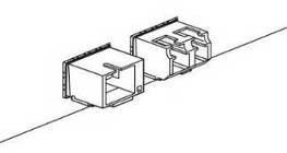
Figure 50 — SFP transceivers installation
To remove a transceiver:
- Step 1. Unlock the module latch.
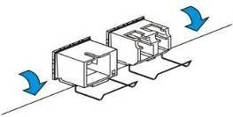
Figure 51 — Opening SFP transceiver latch
- Step 2. Remove the module from the slot.
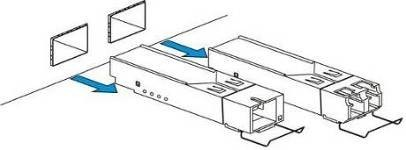
Figure 52 — SFP transceivers removal
Ventilation units replacement
The terminal design allows ventilation units replacement even when the terminal is on.
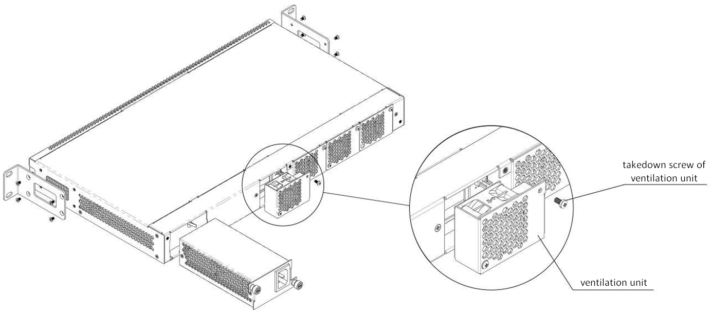
Figure 53 — Ventilation unit. Installation to the case
To remove a ventilation unit:
- Step 1. Use a screwdriver to remove the right screw fixing the ventilation unit to the rear panel (see Figure 53).
- Step 2. Carefully pull the unit until it is removed from the case.
- Step 3. Disengage the pins of the unit from the connector in the device (see Figure 54).
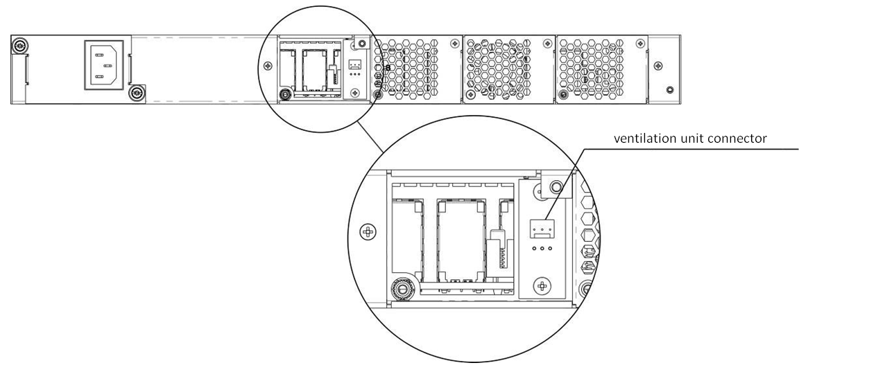
Figure 54 — Ventilation unit socket
To install a ventilation unit, perform the following actions:
- Step 1. Connect the pins of the unit with the connector in the device (see Figure 54).
- Step 2. Lay the connection cable in a special tray on the inner side of the unit.
- Step 3. Insert the unit into the terminal case.
- Step 4. Screw the ventilation unit to the rear panel (see Figure 53).
OLT firmware update
This chapter describes the terminal firmware update procedure. To download a firmware file, use the TFTP server available in the terminal management network.
- Step 1. Copy the firmware file into the root folder (or any other known folder) of the TFTP server.
Step 2. Update the firmware by using the copy command.
LTP-8X# copy ftp://user:pass@10.54.16.1/ltp-8x-revc-revd-3.40.0-buildXXXX.fw.bin fs://firmware Downloading system firmware.. ............................................................ ............................................................ .................................................. Download successfully - speed: 3160145.000 bytes/sec during 5.027 seconds, total size 15885504 System firmware successfully downloaded Updating system firmware.. Current board version: 6 Current firmware version: 3.26.1.1349 New firmware version: 3.32.0.XXXX Update device mtd7 Erase flash... Done. Write data... Done. Done. Success Update device mtd5 Erase flash...Done. Write data... Done. Done. Success System firmware successfully updated
Step 3. Reboot the terminal to start the new firmware.
LTP-8X# reboot Do you really want to reboot the system now? (y/n) y
ONT firmware update
This chapter describes different methods of ONT firmware update using the OMCI protocol.
ONT firmware update download
ONT firmware update can run automatically for all ONTs or for a specified ONT. To start the update, download a firmware update file to the line terminal. To download the file, use the copy command and specify the file name and the address of the TFTP server as arguments.
LTP-8X# copy ftp://user:pass@10.54.16.1/ntp-rg-r3.24.1.854.fw.bin.bin fs://ont-firmware Download file from FTP-server Download successfully - speed: 2906533.000 bytes/sec during 1.008 seconds, total size 2929684 .......................................... .......................................... ONT firmware vendor is Eltex Corporation, version 3.24.1.854 Write downloaded file to flash memory. .......................................... ..........................................
ONT firmware custom update
To update firmware of a specified ONT, you need to create a corresponding task and specify the ONT ID and the firmware file name. There are two types of ONT firmware update tasks: single try or multiple tries.
To create a single try update task, use the update ont command and specify the ONT ID and the file name of the firmware.
LTP-8X# update ont 0/0 filename ntp-rg-r3.24.1.854.fw.bin Task for updated successfully created. ONT firmware will be updated in 20 minutes or more
As a result, the single try update task will be created for the ONT having the specified serial number. This method is used to update the ONTs, which are in the OLT channel at the time of update. The task will end with an error for the ONTs, which are not connected.
To create a multiple tries update task, use a scheduler. This method is generally used to update the ONTs, which are not in the OLT channel at the time of the update. The tasks you create in the scheduler will be executed as soon as the corresponding ONT connects to the channel. To create, delete, or view tasks in the scheduler, use the schedule ont command. To create an ONT firmware update task, use the schedule ont update command and specify the ONT ID and the firmware update file.
LTP-8X# schedule ont update 0/0 ntp-rg-r3.24.1.854.fw.bin Task created for [ONT0/0]
To view scheduled tasks, use the show schedule ont update command.
LTP-8X# show schedule ont update Existing tasks (1): ## Serial Ch/ Id Operation Status Tries remained 0 --- 0/ 0 ont_update scheduled 5
You can delete some of the created tasks by using the no schedule ont update command and specifying the ONTs ID.
LTP-8X# no schedule ont update 0/0 Task deleted for [ONT0/0]
To clear the scheduler, use the clear schedule ont update command.
LTP-8X# clear schedule ont update All tasks cleared
The tasks created in the scheduler will continue running until the update completes successfully or the number of tries is reached (the Tries remained parameter).
ONT firmware autoupdate
To enable firmware autoupdate for all ONTs, use the auto-update ont command and specify the update mode (immediate or postpone).
Step 1. Specify the FW ONT autoupdate mode. The immediate mode enables immediate firmware autoupdate for all connected ONTs. In the postpone mode, ONT firmware update will be performed only upon ONT connection.
LTP-8X# config LTP-8X(config)# auto-update ont postpone Parameter was applied successfullyYou can view the set parameter by using the show auto-update ont command.
LTP-8X(config)# do show auto-update ont Auto-update ONT:postponeStep 2. To enable ONT firmware autoupdate, specify update rules. Specify the ONT model, its current firmware version and the name of the firmware file to be flashed. To do this, use the auto-update ont record command.
Create the update1 autoupdate rule. Pass the ONT type XXX, the current FW version YYY, and the file name ZZZ.bin as parameters.LTP-8X(config)# auto-update ont record update1 equipment-id TYPE fw-version match V1 filename V2.bin Record was added successfullyThe match keyword indicates that the ONT version number should match the specified number, in this case YYY.
To simplify the process and make it more convenient, you can create records to perform firmware autoupdate on ONTs, even when their firmware versions differ from the specified one. Use the non-match parameter when creating the rule.LTP-8X(config)# auto-update ont record update2 equipment-id TYPE fw-version not-match V2 filename V2.bin Record was added successfullyAs a result, the update2 record will be created in the table that will automatically update the ONT with the TYPE and the version not equal to V2 by installing the V2.bin file. This allows autoupdate of all ONTs to the required V2 version.
If the table contains multiple records for one ONT type, autoupdate will be performed by the last rule for this ONT type.
Step 3. You can view the created records by using the show auto-update ont records command.
LTP-8X(config)# do show auto-update ont records Name EquipmentID FWVersion FileName Mode Downgrade update1 TYPE V1 V2.bin global disable update2 TYPE !V2 V2.bin postpone enable
Step 4. You can delete a created record by using the no auto-update ont record command and specifying the record name.
LTP-8X(config)# no auto-update ont record update1 Record was deleted successfully
To clear the record table, use the no auto-update ont records command.
LTP-8X(config)# no auto-update ont records Records cleared successfully
APPENDIX A. RS-232 NULL-MODEM CABLE PIN DESIGNATION
LTP-4/8X rev.B
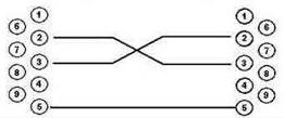
DB-9 Socket DB-9 Socket
LTP-4/8X rev.C, LTP-8X rev.D
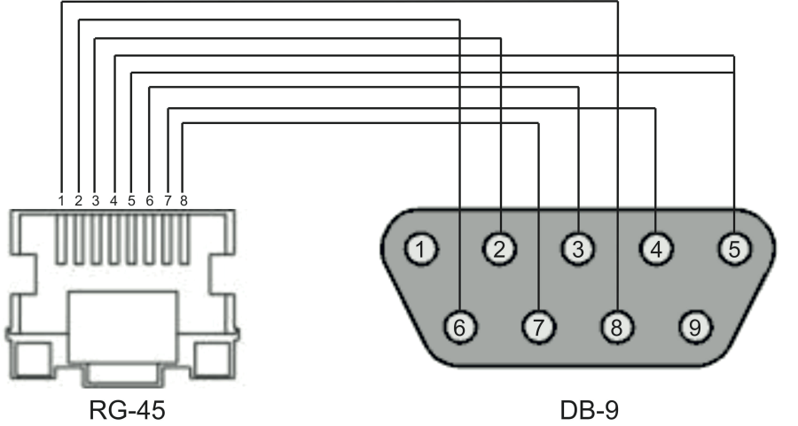
Pin assignment:
- not used
- not used
- RX
- GND
- GND
- TX
- not used
- not used
- not used
APPENDIX B. Configuring services on ONT Ericsson, Atron, CIG
Starting with version 3.36, ONT support has been added for Ericsson T063G, Ericsson T073G, Atron RFT620, Atron PSG590, CIG G-25A-J80. In service configuration on these ONTs, there are some features presented below.
VoIP configuration
To configure VoIP, you need to create two new profiles: cross-connect type voice, profile voice.
Step 1. Create required profiles.
LTP-8X(config)# profile cross-connect "VOICE-ERCS" LTP-8X(config-cross-connect)("VOICE-ERCS")# description "For VOICE ont Ericsson" LTP-8X(config-cross-connect)("VOICE-ERCS")# bridge LTP-8X(config-cross-connect)("VOICE-ERCS")# bridge group "5" LTP-8X(config-cross-connect)("VOICE-ERCS")# outer vid 354 LTP-8X(config-cross-connect)("VOICE-ERCS")# user vid 354 LTP-8X(config-cross-connect)("VOICE-ERCS")# type "voice" LTP-8X(config-cross-connect)("VOICE-ERCS")# exit LTP-8X(config)# profile voice "voice-00-ERCS" LTP-8X(config-voice)("voice-00-ERCS")# sip proxy "123.test.ru" LTP-8X(config-voice)("voice-00-ERCS")# sip outbound-proxy "172.20.20.201" LTP-8X(config-voice)("voice-00-ERCS")# sip domain "123.test.ru" LTP-8X(config-voice)("voice-00-ERCS")# exitStep 2. Assign profiles to ONT and configure additional VoIP data.
LTP-8X(config)# interface ont 0/2 LTP-8X(config)(if-ont-0/2)# service 0 profile cross-connect "VOICE-ERCS" dba "dba-00" LTP-8X(config)(if-ont-0/2)# profile voice "voice-00-ERCS" LTP-8X(config)(if-ont-0/2)# voice port 0 number "402153" LTP-8X(config)(if-ont-0/2)# voice port 0 authentication username "402153" LTP-8X(config)(if-ont-0/2)# voice port 0 authentication password "QFxy2EzfVdrL1"
Step 3. If necessary, configure Value Added Services for the ONT.
LTP-8X(config)(if-ont-0/2)# voice fax-mode t38 LTP-8X(config)(if-ont-0/2)# voice features call-presentation special-dialtone LTP-8X(config)(if-ont-0/2)# voice features call-presentation visual LTP-8X(config)(if-ont-0/2)# voice features call-presentation call-forward LTP-8X(config)(if-ont-0/2)# voice features call-progress 3way LTP-8X(config)(if-ont-0/2)# voice features call-progress transfer LTP-8X(config)(if-ont-0/2)# voice features call-progress hold LTP-8X(config)(if-ont-0/2)# voice features call-progress park LTP-8X(config)(if-ont-0/2)# voice features call-progress emergency-hold LTP-8X(config)(if-ont-0/2)# voice features call-progress 6way LTP-8X(config)(if-ont-0/2)# voice features call-wait enable LTP-8X(config)(if-ont-0/2)# voice features call-wait call-id-annonce LTP-8X(config)(if-ont-0/2)# voice features cid call-number LTP-8X(config)(if-ont-0/2)# voice features cid call-name
LTP-8X(config)(if-ont-0/2)# voice features cid cid-number LTP-8X(config)(if-ont-0/2)# voice features cid cid-name
Step 4. Apply the changes.
LTP-8X(config)(if-ont-0/2)# do commit
Internet and IPTV services configuration
These services are configured similarly to ONT ELTEX.
The list of changes
Firmware version | Document version | Issue date | Revisions |
|---|---|---|---|
| Version 3.46.0 | Issue 22 | 02.11.2022 | Synchronization with firmware version 3.46.0. |
| Version 3.44.0 | Issue 21 | 13.12.2021 | Synchronization with firmware version 3.44.0. |
| Version 3.42.2 | Issue 20 | 30.11.2021 | Synchronization with firmware version 3.42.2. |
| Version 3.42.1 | Issue 19 | 14.10.2021 | Synchronization with firmware version 3.42.1. |
| Version 3.42.0 | Issue 18 | 31.05.2021 | Added:
Added sections: Fixed:
|
| Version 3.40.2 | Issue 17 | 28.04.2021 | Synchronization with firmware version 3.40.2. |
| Version 3.40.0 | Issue 16 | 10.12.2020 | Added:
Sections added:
Fixed:
|
| Version 3.38.2 | Issue 15 | 20.05.2020 | Synchronization with firmware version 3.38.2. |
| Version 3.38.1 | Issue 14 | 07.02.2020 | Synchronization with firmware version 3.38.1. |
| Version 3.38.0 | Issue 13 | 13.12.2019 | Synchronization with firmware version 3.38.0. Sections added:
Changes:
|
| Version 3.36.2 | Issue 12 | 08.10.2019 | Synchronization with firmware version 3.36.2. |
| Version 3.36.0 | Issue 11 | 07.02.2019 | Added:
Sections added:
Added description:
|
Version 3.32.0 | Issue 10 | 03.07.2018 | Added:
Sections added:
Added description:
Changes:
|
Version 3.30.0 | Issue 9 | 30.11.2017 | Added:
Sections added:
Added description:
Changes:
|
Version 3.26.1 | Issue 8 | 13.12.2016 | Added:
|
Version 3.26.0 | Issue 7 | 09.07.2016 | Added:
Changes:
|
Version 3.24.3 | Issue 6 | 25.04.2016 | Added:
|
Version 3.24.1 | Issue 5 | 17.12.2015 | Added:
|
Version 3.24.0 | Issue 4 | 02.09.2015 | Added:
|
Version 3.20.2 | Issue 3 | 25.07.2014 | Added:
|
Issue 2 | 24.04.2014 | Changes:
| |
Issue 1 | 21.04.2014 | Added:
Changes:
|
TECHNICAL SUPPORT
For technical assistance in issues related to handling Eltex Ltd. equipment, please, address to Service Center of the company:
Feedback form on the website: https://eltex-co.com/support/
Servicedesk: https://servicedesk.eltex-co.ru
Visit Eltex official website to get the relevant technical documentation and software, benefit from our knowledge base, send us online request or consult a Service Centre Specialist in our technical forum.
Official website: https://eltex-co.com/
Download center: https://eltex-co.com/support/downloads