Firmware version 1.7.0 (12.2023)
Terms and definitions
AAA – Authentication, Authorization, Accounting
ACL – Access Control List
ACS – Automatic Configuration Server
BRAS – Broadband Remote Access Server
BSS – Business Support System
CBR – Constant Bitrate
CLI – Command Line Interface
CPU – Central Processing Unit
DBA – Dynamic Bandwidth Allocation
DHCP – Dynamic Host Configuration Protocol
DDMI – Digital Diagnostic Monitoring Interface
ERPS – Ethernet Ring Protection Switching
FTP – File Transfer Protocol
FW – Firmware
FEC – Forward Error Correction
GPON – Gigabit PON
XGS-PON — 10 Gigabit PON
HSI – High Speed Internet
HDTV – High Definition Television
HTTP – HyperText Transfer Protocol
IGMP – Internet Group Management Protocol
IP – Internet Protocol
LAG – Link Aggregation Group
LACP - Link Aggregation Control Protocol
MAC – Media Access Control
MLD – Multicast Listener Discovery
OLT – Optical Line Terminal
ONT – Optical Network Terminal
ONU – Optical Network Unit
OSS – Operation Support System
PCB – Printed Circuit Board
PPPOE – Point-to-Point Protocol over Ethernet
QoS – Quality of Service
RAM – Random Access Memory
RSSI – Received Signal Strength Indicator
SLA – Service Level Agreement
SNTP – Simple Network time protocol
SNMP – Simple Network Management Protocol
SFP – Small Form-factor Pluggable
SSH – Secure Shell
SN – Serial Number
TFTP – Trivial File Transfer Protocol
TTL – Time to live
TCP – Transmission Control Protocol
T-CONT – Traffic Container
UDP – User Datagram Protocol
URI – Uniform Resource Identifier
VEIP – Virtual Ethernet Interface Point
VLAN – Virtual Local Area Network
VoD – Video on Demand
Notes and warnings
Notes contain important information, tips or recommendations on device operation and configuration.
Warnings are used to inform the user about harmful situations for the device and the user alike, which could cause malfunction or data loss.
General information
Introduction
GPON and XGS-PON are varieties of Passive Optical Networks (PON). GPON network provides data transfer with downstream rate up to 2.5 Gbps and upstream rate up to 1.25 Gbps. XGS-PON network provides data transfer with downstream rate up to 10 Gbps and upstream rate up to 10 Gbps. GPON and XGS-PON are one of the most modern and efficient last mile solutions, allowing significant savings on cable infrastructure.
Use of solutions based on GPON/XGS-PON technologies in access networks makes it possible to provide the end user with access to new services based on IP protocol together with traditional services.
The key PON advantage is the use of one Optical Line Terminal (OLT) for multiple Optical Network Terminals (ONT). OLT converts Gigabit Ethernet and GPON/XGS-PON interfaces and is used to connect a PON network with data communication networks of a higher level.
The range of OLT GPON equipment produced by ELTEX presents LLTP-8(16)N(T) terminals of 8 and 16 GPON ports with internal Ethernet switch with RSSI function. OLT XGS-PON equipment produced by ELTEX presents LTX-8(16) terminals of 8 and 16 XGS-PON (operation in GPON mode is also possible) ports with internal Ethernet switch with RSSI function.
This user manual describes purpose, main technical specifications, installation order, rules of configuration, monitoring, and software update for the devices.
Purpose
The LTP-8(16)N(T) and LTX-8(16) optical line terminal are designed to establish connection with upstream equipment and provide broadband access via passive optical networks. Ethernet connection is established through Gigabit uplink and 10GE interfaces for LTP-8(16)N(T) and 100GE interfaces for LTX-8(16). GPON and XGS-PON interfaces are used to connect to optical networks. Each PON interface allows connection of up to 128 subscribers, and each XGS-PON allows connection of up to 256 subscribers through one fiber with support for Dynamic Bandwidth Allocation (DBA).
The following services are provided to end users:
- voice communications;
- HDTV;
- VoIP;
- high-speed access to the Internet;
- IPTV;
- video-on-demand (VoD);
- video conferencing;
- online educational and entertainment programs.
The device supports the following functions:
- Dynamic Bandwidth Allocation (DBA);
- QoS, Strict priority + WRR, prioritization of various types of traffic at the GPON/XGS-PON port level in accordance with 802.1p;
- security functions;
- remote ONT management, automatic detection of new ONTs;
- Forward Error Correction (FEC);
- power measurement support for signals received from each ONT (RSSI);
- VLAN organisation (VLAN ID range: 0–4094);
- IGMP snooping v1/2/3, IGMP proxy;
- DHCP snooping, DHCP relay agent;
- PPPoE IA;
- Jumbo frames up to 2000 bytes (supported on NTU-1 and SFP-NTU-100, SFP-NTU-200).
Delivery package
The standard delivery package includes:
- LTP-8(16)N(T) or LTX-8(16) optical line terminal;
- Mounting set for 19'' rack;
- RJ-45 – DB9(F) console cable;
- CD with User Manual and Quick Configuration Guide (optional);
- Power cable (if equipped with 220 V power supply);
- Technical passport.
Technical specifications
Table 1 – Main specifications of the LTP-8(16)N(T) line terminal
| Interfaces | ||||
|---|---|---|---|---|
| LTP-8N | LTP-16N(T) | |||
| Ethernet interfaces (Uplink) | ||||
| Number | 4 | 8 | ||
| Transmission rate | 10GE (SFP+)/1GE (SFP) | |||
| PON interfaces (Downlink) | ||||
Number | 8 | 16 | ||
| Transmission rate | 2.5/1.25 Gbps | |||
| Transmission medium | SMF optic fiber cable – 9/125, G.652 | |||
| Port type | SFP+ | |||
| Split ratio | 1:4, 1:8, 1:16, 1:32, 1:64, 1:128 | |||
| Class B+ | Class C++ | Class B+ | Class C++ | |
| Coverage range | 20 km | 40 km | 20 km | 40 km |
| Transmitter | 1490 nm DFB Laser | 1490 nm DFB Laser | ||
| Transmission rate | 2488 Mbps | 2488 Mbps | ||
| Average output power | +1.5..+5 dBm | +7..+10 dBm | +1.5..+5 dBm | +7..+10 dBm |
| Spectral line width at -20 dB | 1.0 nm | 1.0 nm | ||
Receiver | 1310 nm APD/TIA | 1310 nm APD/TIA | ||
Transmission rate | 1244 Mbps | 1244 Mbps | ||
| Receiver sensitivity | -28 dBm | -32 dBm | -28 dBm | -32 dBm |
| Receiver optical overload | -8 dBm | -12 dBm | -8 dBm | -12 dBm |
| Synchronization ports | ||||
| Number | – | 2 (only for LTP-16NT) | ||
| OOB interface | ||||
| Number | 1 | |||
| Transmission rate | 10/100/1000 Mbps | |||
| RS-232 (RJ-45) console interface | ||
|---|---|---|
| Number | 1 | |
| Processor | ||
| Clock speed | 2.2 GHz | |
| Number of cores | 4 | |
| RAM | 8 GB | |
| Non-volatile memory | no less than 8 GB | |
| Switch | ||
| Performance | 120 Gbps | |
| MAC addresses table | 64К entries | |
| VLAN | up to 4К in accordance with 802.1Q | |
| QoS | 8 egress queues per port | |
| Management | ||
| Local management | CLI – Command Line Interface | |
| Remote management | CLI (SSH2, Telnet) SNMP, RADIUS, TACACS+ | |
| Monitoring | CLI, SNMP | |
| Access restriction | by password, by privilege level | |
| General parameters | ||
| Power supplies | AC: 100–240 V, 50 Hz DC: 36–72 V Power options:
| |
| LTP-8N | LTP-16N(T) | |
| Power consumption | no more than 55 W | no more than 65 W |
| Operating temperature | from -5 to +40 °C | |
| Operating humidity | up to 80 % | |
| Dimensions (W × H × D) | 430 × 44 × 317 mm (with installed power module), 19", 1U | |
| Weight | 4.4 kg | 4.5 kg |
| Lifetime | at least 15 years | |
Table 2 – Main specifications of the LTX-8(16) optical terminal
| Interfaces | ||||
|---|---|---|---|---|
| LTX-8 | LTX-16 | |||
| Ethernet interfaces (Uplink) | ||||
| Number | 4 | |||
| Transmission rate | 100GE (QSFP28) | |||
| PON interfaces (Downlink) | ||||
Number | 8 | 16 | ||
| Transmission rate | 10/10 Gbps | |||
| Transmission medium | SMF optic fiber cable – 9/125, G.652 | |||
| Port type | QSFP | |||
| Split ratio | 1:4, 1:8, 1:16, 1:32, 1:64, 1:128, 1:256 | |||
| Class B+ | ||||
| Coverage range | 20 km | |||
| Transmitter | 1577 nm DFB Laser | |||
| Transmission rate | 9.953 Gbps | |||
| Average output power | +2..+5 dBm | |||
| Spectral line width at -20 dB | 1.0 nm | |||
| Receiver | 1270 nm APD/TIA | |||
| Transmission rate | 9.953 Gbps | |||
| Receiver sensitivity | -26 dBm | |||
| Receiver optical overload | -8 dBm | |||
| OOB interface | ||||
| Number | 1 | |||
| Transmission rate | 10/100/1000 Mbps | |||
| RS-232 (RJ-45) console interface | |
| Number | 1 |
| Processor | |
|---|---|
| Clock speed | 2.2 Hz |
| Number of cores | 4 |
| RAM | 8 GB |
| Non-volatile memory | no less than 8 GB |
| Switch | |
| Performance | 120 Gbps |
| MAC address table | 64К entries |
| VLAN | up to 4К in accordance with 802.1Q |
| QoS | 8 egress queues per port |
| Management | |
| Local management | CLI – Command Line Interface |
| Remote management | CLI (SSH2, Telnet) SNMP, RADIUS, TACACS+ |
| Monitoring | CLI, SNMP |
| Access restriction | by password, by IP address, by privilege level |
| General parameters | |
| Power supplies | AC: 100–240 V, 50 Hz DC: 36–72 V Power options:
|
| Power consumption | no more than 108 W |
| Operating temperature | from -5 to +40 °C |
| Operating humidity | up to 80 % |
| Dimensions (W × H × D) | 430 × 43.6 × 451.2 mm (with installed power module), 19", 1U |
| Weight | 6.2 kg |
| Lifetime | at least 15 years |
Compatible SFP transceivers
Correct and error-free operation of GPON/XGS-PON interface requires exact parameters to be chosen and set for each transceiver type. This can be done only under laboratory conditions by the terminal vendor. Table 3 lists SFP transceivers for GPON and table 4 lists SFP transceivers for XGS-PON for which seamless terminal operation is guaranteed.
DDMI (Digital Diagnostic Monitoring Interface) provides information on transceiver parameters, such as temperature, power voltage, etc. DDMI also measures the level of ONT signal (RSSI). All compatible transceivers support this function.
Table 3 – List of compatible SFP transceivers for GPON
SFP transceiver module | Class | DDMI |
|---|---|---|
LTE3680M-BC+ | B+ | + |
LTE3680P-BC+2 | C++ | + |
Table 4 – List of compatible SFP transceivers for XGS-PON
SFP transceiver module | Class | DDMI |
|---|---|---|
LTF7226B-BC+ | B+ | + |
LTF7226B-BCB+ | C++ | + |
Safety rules and installation procedure
This section describes safety measures and installation of the terminal into a rack and connection to a power supply.
Safety requirements
General requirements
Any operation with the equipment should comply with the Rules for the technical operation of consumer electrical installations.
Operations with the terminal should be carried out only by personnel authorized in accordance with the safety requirements.
- Before operating the device, all engineers should undergo special training.
- Connect only serviceable and compatible accessories to the terminal.
To avoid overheating and provide necessary ventilation of the terminal, sufficient space should be provided above and below the terminal. - The device is meant for 24/7 operation if the following requirements are met:
- ambient temperature from -5 to +40 °C;
- relative humidity up to 80 % at +25 °C;
- atmosphere pressure from 6.0×10*4 to 10.7×10*4 Pa (from 450 to 800 mm Hg).
- The terminal should not be exposed to mechanical shock, vibration, smoke, dust, water, and chemicals.
- To avoid components overheating which may result in device malfunction, do not block air vents or place objects on the equipment.
Electrical safety requirements
- Prior to connecting the device to a power source, ensure that the equipment case is grounded with an earth bonding point. The earthing wire should be securely connected to the earth bonding point. The resistance between the earth bonding point and earthing busbar should be less than 0.1 Ω. PC and measurement instruments should be grounded prior to connection to the terminal. The potential difference between the equipment case and the cases of the instruments should be less than 1V.
- Prior to turning the device on, ensure that all cables are undamaged and securely connected.
- Make sure the device is off, when installing or removing the case.
- Follow the instructions given in SFP transceivers replacement to install or remove SFP transceivers. This operation does not require the terminal to be turned off.
LTP-8(16)N(T) design
LTP-8(16)N(T) front panel
The devices have a metal housing of 1U size available for 19” form-factor rack mount. The front panel layout is shown in figures 1, 2, 3. Table 5 list interfaces, LEDs and controls located on the front panel of the terminal.
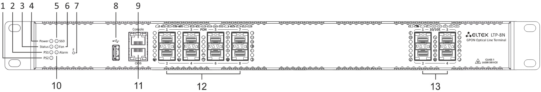
Figure 1 – LTP-8N front panel
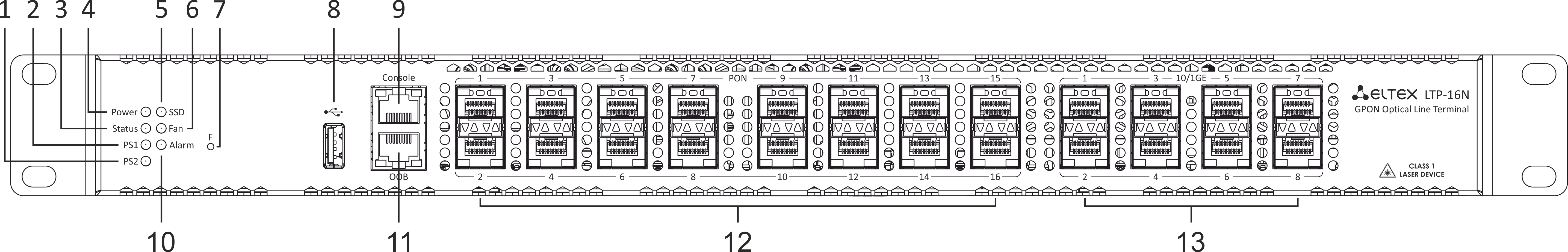
Figure 2 – LTP-16N front panel layout
Table 5 – Description of connectors, LEDs, and controls located on the front panel of LTP-8(16)N
№ | Front panel element | Description |
|---|---|---|
1 | PS2 | Redundant power supply indicator |
2 | PS1 | Primary power supply indicator |
3 | Status | Device operation indicator |
4 | Power | Device power indicator |
5 | SSD | SSD operation indicator |
6 | FAN | Ventilation panels operation indicator |
7 | F | Functional key that reboots the device and resets it to factory default configuration:
The reaction to a button press is configured in the CLI of the terminal in the System environment configuration section. |
8 | USB | USB port |
9 | Console | DB9F — RJ45 console port |
10 | Alarm | Alarm indicator |
11 | OOB | Port for connection to the board via network |
12 | PON 1..8 PON 1..16 | GPON interfaces. 8 chassis for installing xPON 2.5G SFP modules (for LTP-8N) GPON interfaces. 16 chassis for installing xPON 2.5G SFP modules (for LTP-16N) |
13 | 10/1GE | Uplink interfaces. 4 chassis for installing 10GE SFP modules (for LTP-8N) Uplink interfaces. 8 chassis for installing 10GE SFP modules (for LTP-16N) |
LTP-8(16)N(T) rear panel
The rear panel of the device is shown in Figure 3.
Table below lists rear panel connectors.

Figure 3 – LTP-8(16)N(T) rear panel
Table 6 – Description of LTP-8(16)N(T) rear panel
Rear panel element | Description |
|---|---|
160..250 VAC, 50Hz, max 1A | Connectors for AC/DC power supply |
Earth bonding point | Earth bonding point |
Fan1, Fan2 | Ventilation units |
LTP-8(16)N(T) LED indication
The indicators located on the front panel show the status of the terminal. Table 7 provides possible statuses of the LEDs.
Table 7 – LTP-16N/16NT status light indication
LED name | Indicator State | Device state |
|---|---|---|
Power | Solid green | Power is on, normal device operation |
Off | Power is off | |
Red | Primary power supply failure | |
Status | Solid green | Normal operation |
Solid red | Operation failures | |
Fan | Solid green | All fans are operational |
Flashing red | One or more fans are failed | |
PS1 | Solid green | Primary power supply is connected and operates correctly |
Disabled | Primary power supply is not connected | |
Red | Primary power supply is missing or failed. | |
PS2 | Solid green | Redundant power supply is connected and operates correctly |
Disabled | Redundant power supply is not connected | |
Red | The primary source of the redundant power supply is unavailable or the redundant power supply failed | |
Alarm | Green | Correct device operation |
Flashing red | Alarm | |
SSD | Disabled | Cannot reach the drive |
Flashing green | The drive is being accessed | |
Sync | Solid green | Synchronization is in process |
Disabled | Synchronization is disabled |
LTP-8(16)N(T) temperature sensors
Four temperature sensors are used to measure temperature inside the terminal case: three external and one built into switch.
Figure 4 shows the sensor location on PCB.
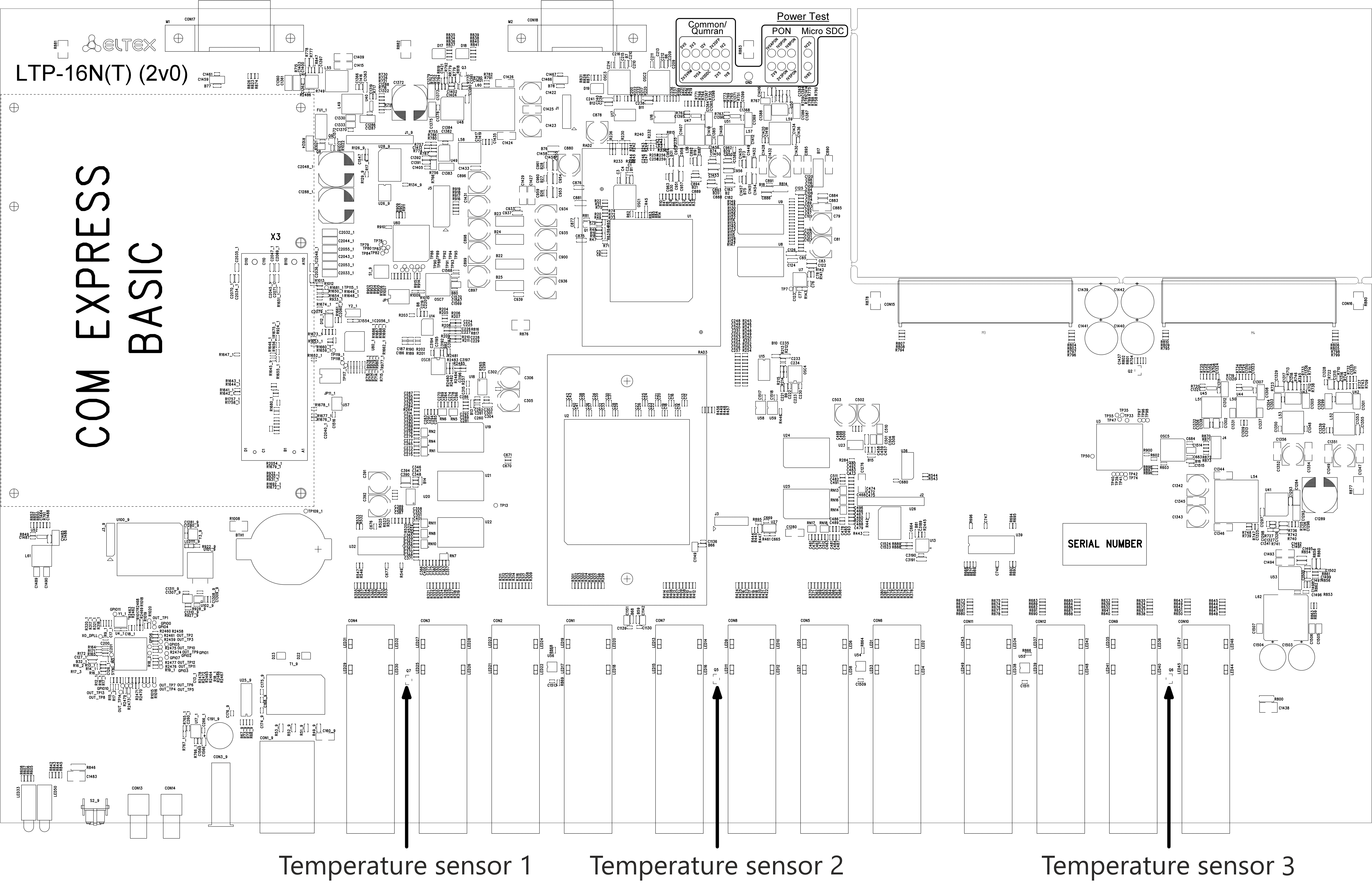
Figure 4 – LTP-8(16)N(T) temperature sensors location
Table 8 – Temperature sensors description
Element | Description |
|---|---|
Temperature sensor 1 | PON-ports SFP 1 |
Temperature sensor 2 | PON-ports SFP 2 |
Temperature sensor 3 | Front-ports SFP |
Temperature sensor 4 | Switch |
LTP-8(16)N(T) ventilation system
There are ventilation openings on the device rear, front and side panels for heat dissipation. There are two ventilation units on the rear panel (Figure 3).
Air flows in through the perforated front and side panels, circulates through all internal components, cools them down, and then is removed by fans located on the perforated rear panel.
The device contains two blocks of two fans each. The ventilation units are detachable. The procedure for dismantlement and installation is described in Ventilation units replacement.
LTP-8(16)N(T) terminal installation
Check the device for visible mechanical damage before installing and turning it on. In case of any damage, stop the installation, fill in a corresponding document and contact your supplier. If the terminal has been at low temperatures for a long time before installation, leave it for 2 hours at ambient temperature prior to operation. If the device has been at high humidity for a long time, leave it for at least 12 hours in normal conditions prior to turning it on.
Support brackets mounting
The delivery package includes support brackets for rack installation and mounting screws to fix the terminal case on the brackets. To install the support brackets:
- Step 1. Align six mounting holes in the support bracket with the corresponding holes in the side panel of the device.
- Step 2. Use a screwdriver to attach the support bracket to the case.
- Step 3. Repeat steps 1 and 2 for the second support bracket.
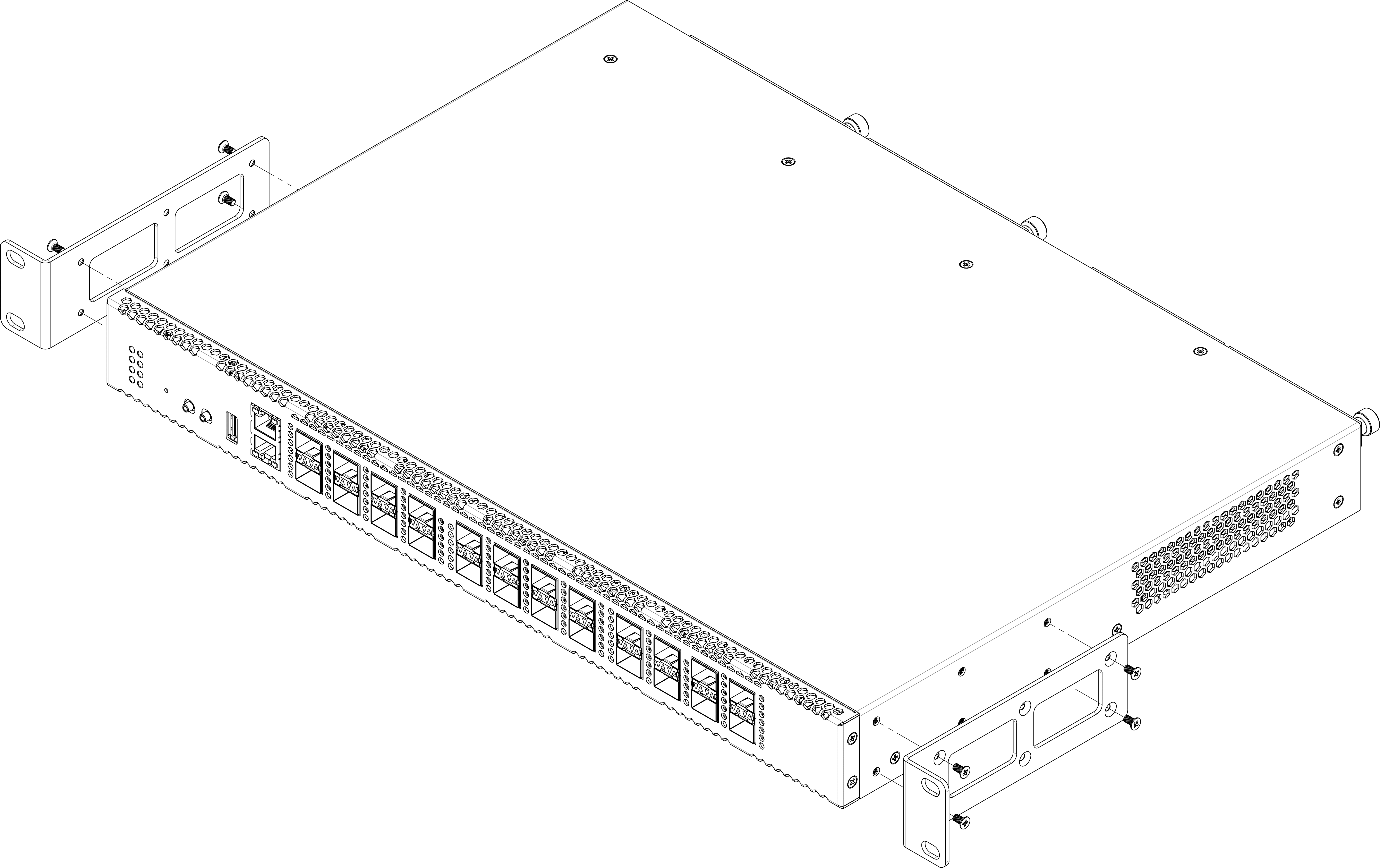
Figure 5 – Support brackets mounting
Terminal rack installation
To install the terminal to the rack:
- Step 1. Attach the terminal to the vertical guides of the rack.
- Step 2. Align mounting holes in the support bracket with the corresponding holes in the rack guides. Use the holes of the same level on both sides of the guides to ensure the device horizontal installation.
- Step 3. Use a screwdriver to attach the terminal to the rack.
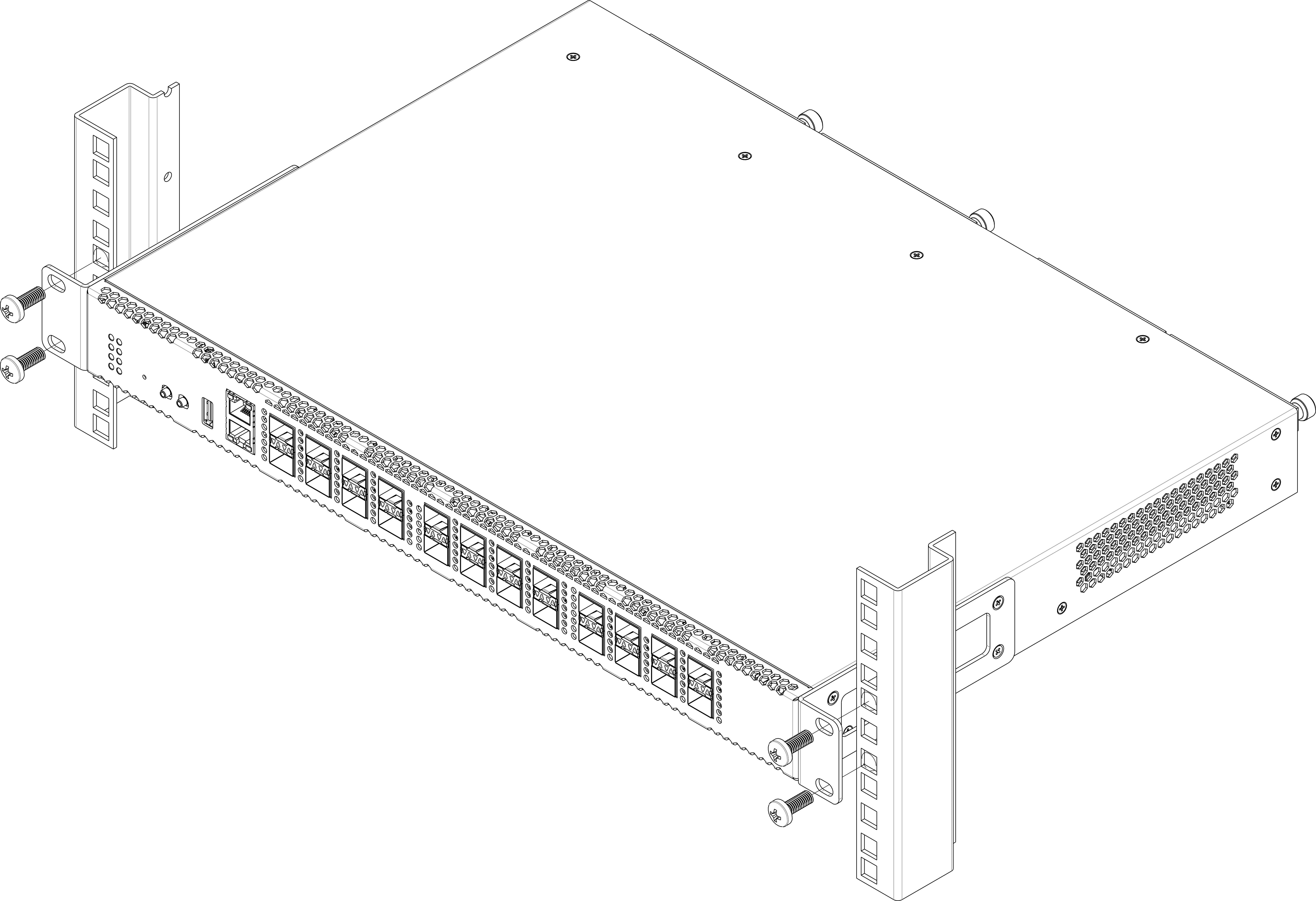
Figure 6 – Device rack installation
The terminal is horizontally ventilated. The side panels have air vents. Do not block the air vents to avoid components overheating and subsequent terminal malfunction.
Power module installation
Depending on power supply requirements, LTP-8N, LTP-16N and LTP-16NT can be supplemented with either 220 V, 50 Hz AC power module or 48 V DC power supply module. Location of the power module is shown in Figure 7.
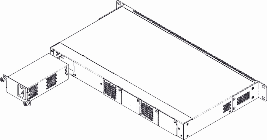
Figure 7 – Power module installation for LTP-8(16)N(T)
Terminals can operate with one or two power modules. The second power module installation is necessary when greater reliability is required. In case of using two power supply modules, it is allowed to use different power modules for supplying (with different voltage).

Figure 8 – Power modules installation for LTP-8(16)N(T)
From the electric point of view, both places for power module installation are identical. In the terms of device operation, the power supply module located closer to the edge is considered as the main module, and the one closer to the centre — as the backup module. Power modules can be inserted and removed without powering the device off. When an additional power module is inserted or removed, the device continues to operate without reboot.
Power module installation procedure:
- Step 1. Install the power module into the socket shown in Figure 7 or Figure 8.
- Step 2. Attach the module to the case.
- Step 3. Follow the instructions in Terminal installation to power on.
Device installation procedure:
- Step 1. Mount the device. In case of installation to a 19" form-factor rack, mount the support brackets from the delivery package to the rack.
- Step 2. Ground the case of the device. This should be done prior to connecting the device to the power supply. An insulated multiconductor wire should be used for earthing. The device grounding and the earthing wire section should comply with Electric Installation Code. The ground terminal is on the rear panel, Figure 3.
- Step 3. If you intend to connect a PC or another device to the switch console port, the device must be properly grounded as well.
- Step 4. Connect the power supply cable to the device.
- Step 5. Turn the device on and check the front panel LEDs to make sure the terminal is in normal operating conditions.
LTX-8(16) design
LTX-8(16) front panel
The devices have a metal housing of 1U size available for 19” form-factor rack mount. The front panel layout is shown in figures below. Tables 9 and 10 list interfaces, LEDs and controls located on the front panel of the terminal.

Figure 9 – LTX-8 front panel

Figure 10 – LTX-16 front panel
Table 9 – Description of connectors, LEDs, and controls located on the front panel of LTX-8(16)
№ | Front panel element | Description | |
|---|---|---|---|
| 1 | PS2 | Redundant power supply indicator | |
| 2 | PS1 | Primary power supply indicator | |
3 | Status | Device operation indicator | |
4 | Power | Device power indicator | |
| 5 | SSD | SSD operation indicator | |
| 6 | FAN | Ventilation panels operation indicator | |
| 7 | F | Functional key that reboots the device and resets it to factory default configuration:
The reaction to a button press is configured in the CLI of the terminal in the System environment configuration section | |
8 | USB | USB port | |
9 | Console | DB9F – RJ45 console port | |
| 10 | Alarm | Alarm indicator | |
| 11 | OOB | Port for connection to the board via network | |
| 12 | PON | XGS-PON interfaces. 8 chassis for installing SFP PON modules (for LTX-8) | |
| XGS-PON interfaces. 16 chassis for installing SFP PON modules (for LTX-16) | |||
| 13 | XLG | Uplink interfaces for connection to IP network. 4×100GE (QSFP28) | |
LTX-8(16) rear panel
The rear panel of the device is shown in Figure 11.
Table below lists rear panel connectors.

Figure 11 – LTX-8(16) rear panel
Table 10 – LTX-8(16) rear panel connectors description
| Rear panel element | Description |
|---|---|
| 160-250 V AC, 36-72 V DC | Connectors for AC/DC power supply |
| Earth bonding point | Earth bonding point |
| Fan1, Fan2 | Ventilation units |
LTX-8(16) LED indication
The indicators located on the front panel show the status of the terminal. Table 11 provides possible statuses of the LEDs.
Table 11 – LTX-8(16) status light indication
LED name | Indicator State | Device state |
|---|---|---|
Power | Solid green | Power is on, normal device operation |
Off | Power is off | |
Red | Primary power supply failure | |
Status | Solid green | Normal operation |
Solid red | Operation failures | |
Fan | Solid green | All fans are operational |
Flashing red | One or more fans are failed | |
PS1 | Solid green | Primary power supply is connected and operates correctly |
Disabled | Primary power supply is not connected | |
Red | Primary power supply is missing or failed | |
PS2 | Solid green | Redundant power supply is connected and operates correctly |
Disabled | Redundant power supply is not connected | |
Red | The primary source of the redundant power supply is unavailable or the redundant power supply failed | |
Alarm | Green | Correct device operation |
Flashing red | Alarm | |
SSD | Disabled | Cannot reach the drive |
Flashing green | The drive is being accessed |
LTX-8(16) temperature sensors
Four temperature sensors are used to measure temperature inside the terminal case.
Figure below shows the sensor location on PCB.
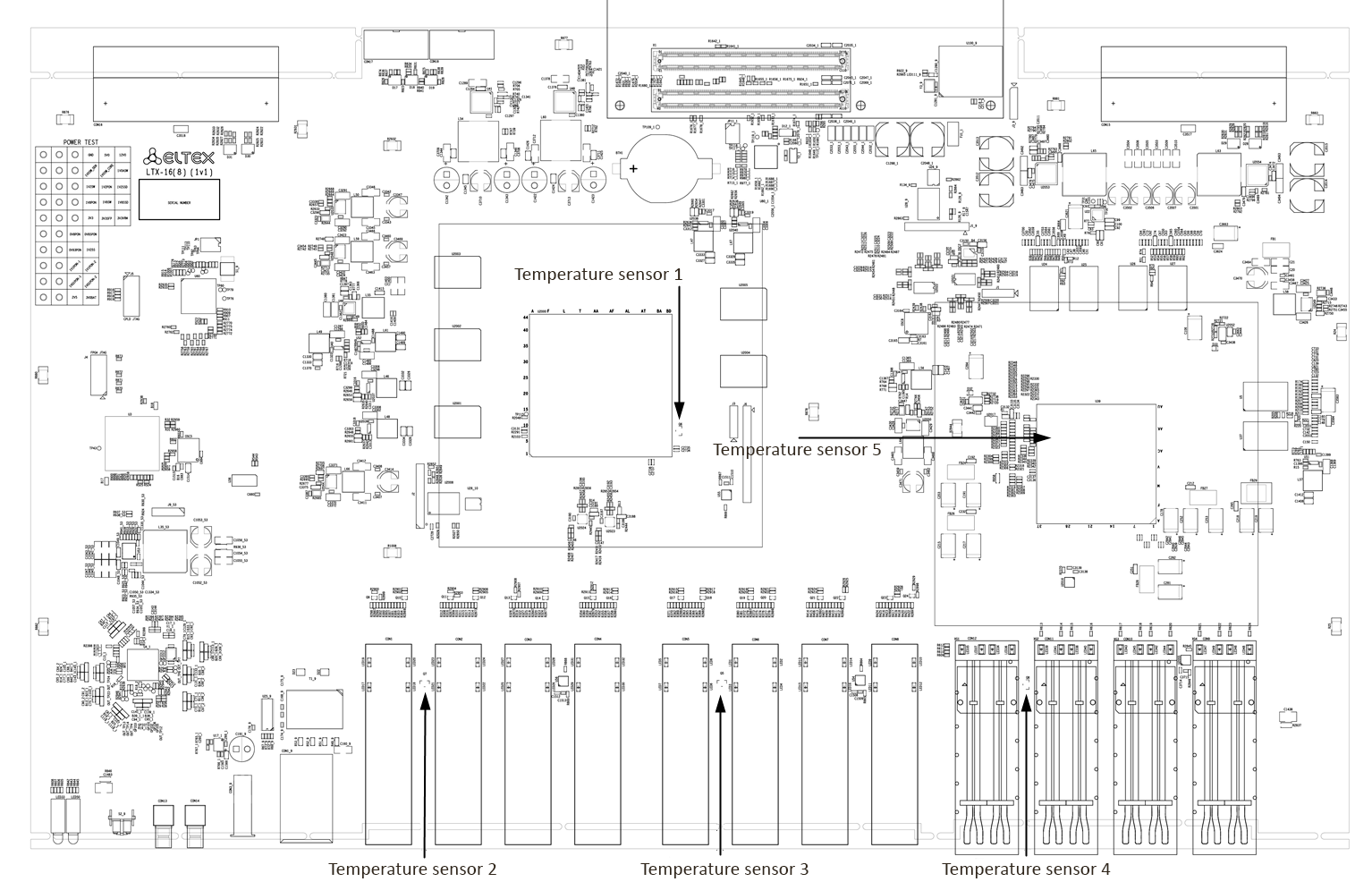
Figure 12 – LTX-8(16) temperature sensors location
Table 12 – Temperature sensors description
| Element | Description |
|---|---|
| Temperature sensor 1 | PON-chip |
| Temperature sensor 2 | PON-ports SFP 1 |
| Temperature sensor 3 (only for LTX-16) | PON-ports SFP 2 |
| Temperature sensor 4 | Front-ports SFP |
| Temperature sensor 5 | Switch |
LTX-8(16) ventilation system
There are ventilation openings on the device rear, front and side panels for heat dissipation. There are two ventilation units on the rear panel (figure 11).
Air flows in through the perforated front and side panels, circulates through all internal components, cools them down, and then is removed by fans located on the perforated rear panel.
The device is equipped with two fans. The ventilation units are detachable. The procedure for dismantlement and installation is described in Ventilation units replacement.
LTX-8(16) terminal installation
Check the device for visible mechanical damage before installing and turning it on. In case of any damage, stop the installation, fill in a corresponding document and contact your supplier. If the terminal has been at low temperatures for a long time before installation, leave it for 2 hours at ambient temperature prior to operation. If the device has been at high humidity for a long time, leave it for at least 12 hours in normal conditions prior to turning it on.
Support brackets mounting
The delivery package includes support brackets for rack installation and mounting screws to fix the terminal case on the brackets. To install the support brackets:
- Step 1. Align four mounting holes in the support bracket with the corresponding holes in the side panel of the device.
- Step 2. Use a screwdriver to attach the support bracket to the case.
- Step 3. Repeat steps 1 and 2 for the second support bracket.
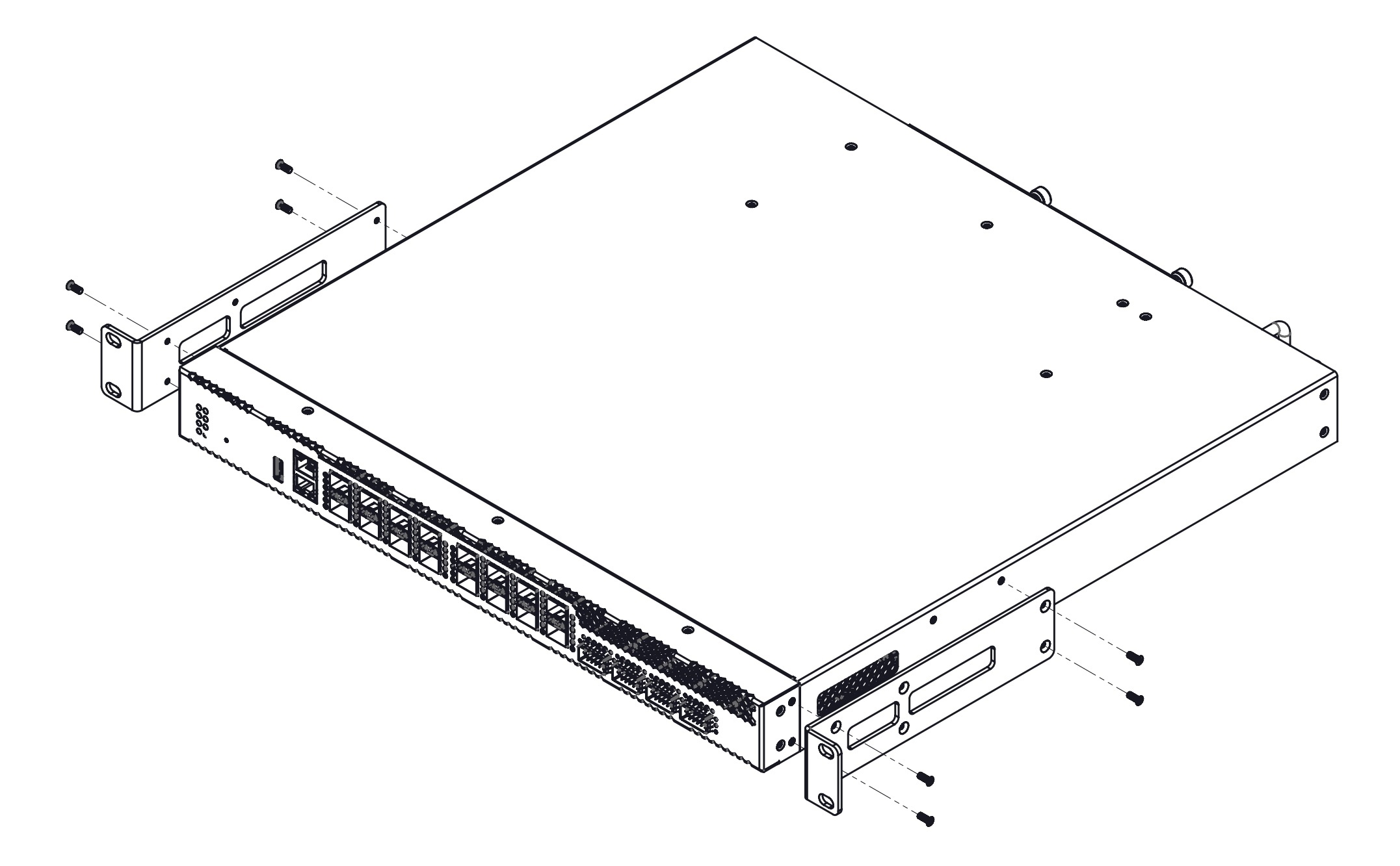
Figure 13 – LTX-8(16) support brackets mounting
Terminal rack installation
To install the terminal to the rack:
- Step 1. Attach the terminal to the vertical guides of the rack.
- Step 2. Align mounting holes in the support bracket with the corresponding holes in the rack guides. Use the holes of the same level on both sides of the guides to ensure the device horizontal installation.
- Step 3. Use a screwdriver to attach the terminal to the rack.
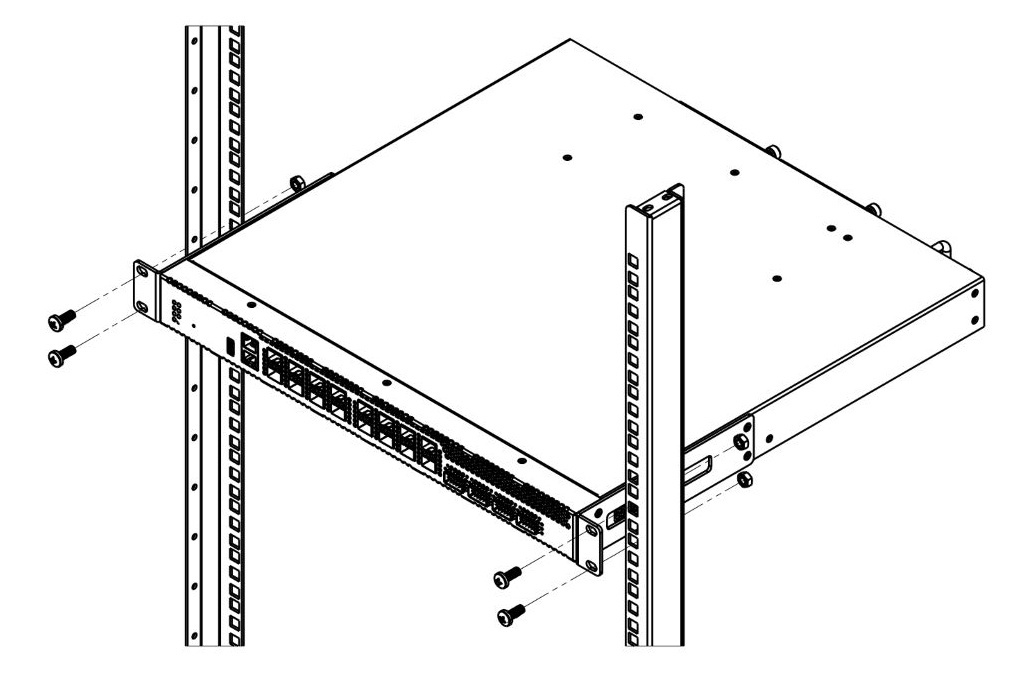
Figure 14 – LTX-8(16) rack installation
The terminal is horizontally ventilated. The side panels have air vents. Do not block the air vents to avoid components overheating and subsequent terminal malfunction.
Power module installation
Depending on power supply requirements, LTX-8 and LTX-16 can be supplemented with either 220 V, 50 Hz AC power module or 48 V DC power supply module. Location of the power module is shown in Figure 15.

Figure 15 – Power module installation for LTX-8(16)
Terminals can operate with one or two power modules. The second power module installation is necessary when greater reliability is required. In case of using two power supply modules, it is allowed to use different power modules for supplying (with different voltage).

Figure 16 – Power modules installation for LTX-8(16)
From the electric point of view, both places for power module installation are identical. In the terms of device operation, the power supply module located closer to the edge is considered as the main module, and the one closer to the centre — as the backup module. Power modules can be inserted and removed without powering the device off. When an additional power module is inserted or removed, the device continues to operate without reboot.
Power module installation procedure:
- Step 1. Install the power module into the socket shown in Figure 15 or Figure 16.
- Step 2. Attach the module to the case.
- Step 3. Follow the instructions in Terminal installation section to power on.
Device installation procedure:
- Step 1. Mount the device. In case of installation to a 19" form-factor rack, mount the support brackets from the delivery package to the rack.
- Step 2. Ground the case of the device. This should be done prior to connecting the device to the power supply. An insulated multiconductor wire should be used for earthing. The device grounding and the earthing wire section should comply with Electric Installation Code. The ground terminal is on the rear panel, figure 11.
- Step 3. If you intend to connect a PC or another device to the switch console port, the device must be properly grounded as well.
- Step 4. Connect the power supply cable to the device.
- Step 5. Turn the device on and check the front panel LEDs to make sure the terminal is in normal operating conditions.
Getting started with the terminal
Connecting to the terminal CLI
This section describes various connection methods for Command Line Interface (CLI) of the terminal.
A serial port (hereafter – COM port) is recommended for preliminary adjustment of the terminal.
Connecting to CLI via COM port
This example shows configuration of LTP-16N(T) terminal. The command syntax is similar for LTX-8(16) and LTP-8N.
This type of connection requires PC either to have an integrated COM port or to be supplied with an USB-COM adapter cable. The PC should also have a terminal program installed, e. g. HyperTerminal.
- Step 1. Use the null modem cable from the delivery package to connect the console port of the terminal to the PC COM port as shown in figure below.
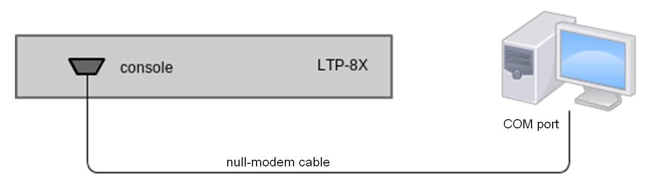
Figure 17 – Connecting the terminal to a PC via COM port
Step 2. Launch the terminal program and create a new connection. Select the corresponding COM port in the Connect to drop-down list. Assign the port settings according to the table below. Click <OK>.
Table 13 – Port specifications
Parameter
Value
Rate 115200 Data bits
8
Parity
No
Stop bits
1
Flow control
None
Step 3. Press <Enter>. Log into the terminal CLI.
Factory default authorization settings:
login: admin, password: password.******************************************** * Optical line terminal LTP-16N * ******************************************** LTP-16N login: admin Password: LTP-16N#
Connecting to CLI via Telnet protocol
The Telnet protocol connection is more flexible than the connection via COM port. Connection to CLI can be established directly at the terminal location or via an IP network with the help of a remote desktop.
This section considers direct connection to CLI at the terminal location. Remote connection is similar, but requires changes in the terminal IP address that will be considered in detail in the Network Settings section.
In order to be connected to the terminal, a PC should have a Network Interface Card (NIC). The connection will additionally require the sufficient amount of network cable (Patching Cord RJ45) as it is not included in the delivery package.
- Step 1. Connect one side of the network cable to OOB port on the terminal. Connect another end to NIC on the PC as shown in figure below.
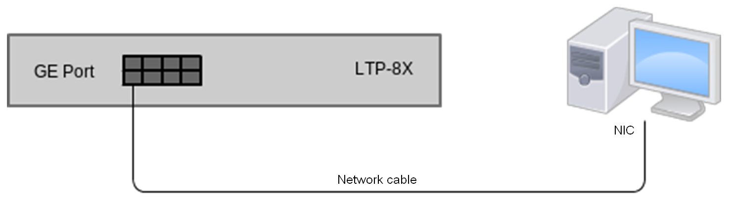
Figure 18 – Connecting the terminal to a PC via network cable
- Step 2. Assign IP settings for network connections. Set 192.168.100.1 as an IP address and 255.255.255.0 as a subnet mask.
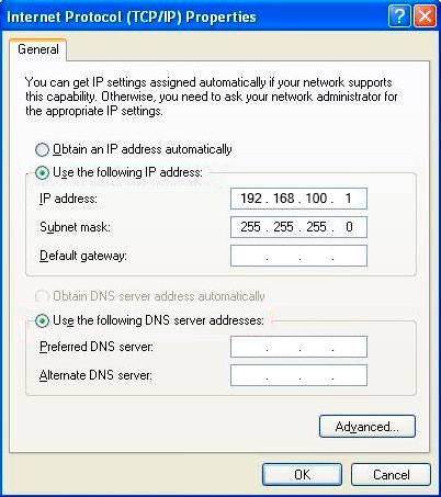
Figure 19 – Network connection configuration
- Step 3. On the PC, click Start > Run. Enter the telnet command and the terminal's IP address. The factory setting for the IP address is 192.168.100.2. Click <OK>.
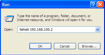
Figure 20 – Client startup
Step 4. Log into the terminal CLI.
Factory authorization settings:
login: admin, password: password.Trying 192.168.100.2... Connected to 192.168.100.2. Escape character is ’^]’. ******************************************** * Optical line terminal LTP-16N * ******************************************** LTP-16N login: admin Password: LTP-16N#
Connecting to CLI via Secure Shell protocol
Secure Shell connection (SSH) has functionality similar to the Telnet protocol. However, as opposed to Telnet, Secure Shell encrypts all traffic data, including passwords. This enables secure remote connection via public IP networks.
This section considers direct connection to CLI at the terminal location. Remote connection is similar, but requires changes in the terminal IP address that will be considered in detail in the Network settings section.
In order to connect to the terminal, a PC should have a Network Interface Card (NIC). The PC should have an SSH client installed, e.g. PuTTY. The connection will additionally require the sufficient amount of network cable (Patch Cord RJ-45) as it is not included in the delivery package.
- Step 1. Perform steps 1 and 2 from the Connecting to CLI via Telnet port
- Step 2. Run PuTTY. Enter IP address of the terminal. The default IP address is 168.1.2. Select port 22 and SSH protocol type. Click <Open>.
Step 3. Log into the terminal CLI. Factory authorization settings:
login: admin, password: password.login: admin Password: ******** LTP-16N#
Getting started with terminal CLI
CLI is the main means of communication between user and the terminal. This section describes general CLI procedures: information on grouping, autocomplete options, and command history is given.
CLI views hierarchy
The command system of the LTP-16N Command Line Interface is divided into views. The transition between views is performed by commands. The exit command is used to return to the previous level. Some views are an array where a unique index must be used to access a specific object.
Figure 21 shows a graphic chart of main views and the commands to switch between them.
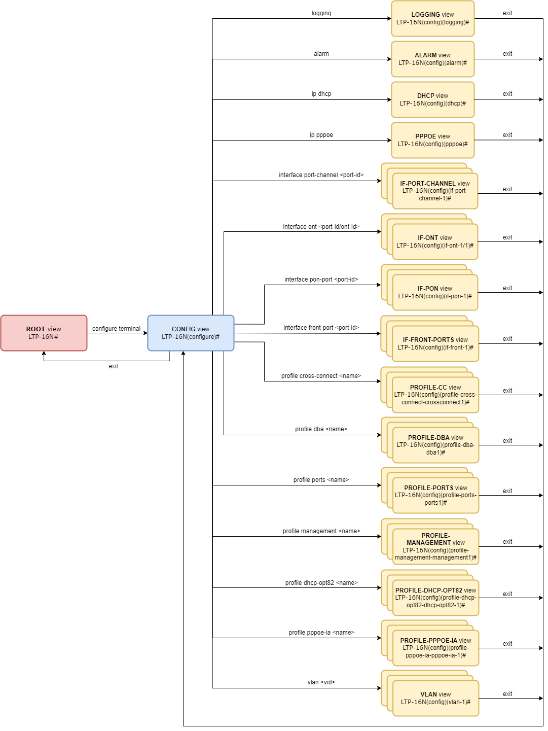
Figure 21 – CLI views hierarchy
CLI hotkeys
To speed up the operations with the command line, the following hotkeys have been added:
Table 14 – Command line hotkeys
Hotkey | Result |
|---|---|
Ctrl+A | Transition to the beginning of line |
Ctrl+D | In a nested command mode – exit to the previous command mode (exit command), in a root command mode – exit from CLI |
Ctrl+E | Transition to the end of line |
Ctrl+L | Screen clearing |
Ctrl+U | Removal of characters to the left of a cursor |
Ctrl+W | Removal of a word to the left of a cursor |
Ctrl+K | Removal of characters to the right of a cursor |
Ctrl+C | Line clearing, command execution interruption |
CLI automatic code completion
To simplify the use of the command line, the interface supports automatic command completion. This function is activated when the command is incomplete and the <Tab> character is entered.
For example, enter the ex command in the Top view and press <Tab>:
LTP-16N# ex<Tab>
LTP-16N# exit
As this mode has only one command with the ex prefix, CLI automatically completes it.
If there are several commands with this prefix, CLI shows hints with possible options:
LTP-16N# co<Tab>
commit configure copy
LTP-16N# con<Tab>
LTP-16N# configure
Group operations
Group operations can be performed on such terminal configuration objects as interfaces and ONTs. It is especially convenient when same actions have to be applied to multiple objects.
To perform a group operation, select the range of object IDs instead of one object ID. This feature is supported by a majority of CLI commands.
For example, enable broadcast-filter for all ONTs in a certain channel.
LTP-16N# configure
LTP-16N(configure)# interface ont 1/1-128
LTP-16N(config)(if-ont-1/1-128)# broadcast-filter
View the list of active ones in the first three PON ports:
LTP-16N# show interface ont 1-3 online
GPON-port 1 has no online ONTs
GPON-port 2 has no online ONTs
GPON-port 3 has no online ONTs
Total ONT count: 0
Configuring the terminal
Terminal configuration
A collection of all terminal settings is referred to as configuration. This section provides information on the parts which configuration consists of. It also defines lifecycle of configuration and describes main operations, which can be performed.
Configuration lifecycle
The terminal configuration may have the following states:
- Running – active configuration. It refers to the current configuration of the terminal.
- Candidate – configuration under review;
- NVRAM – configuration stored in non-volatile memory. This configuration will be used as Running after the device is loaded.
The Running configuration is loaded to a new CLI session and becomes available for editing (Candidate). A different copy of the Candidate configuration is used for each session. After a configuration (Candidate) change in a CLI session, the user can issue a command to apply the changed configuration (the commit command) or to discard the changes (rollback candidate-config command) and get the current active terminal configuration again (Running). The save command saves the Running configuration into NVRAM of the terminal.
Figure 22 shows a chart of configuration lifecycle.
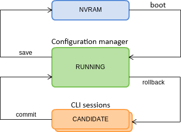
Figure 22 – Configuration lifecycle of the terminal chart
Configuration backup
Configuration backups allow the terminal operation to be quickly restored after abnormal situations or replacement. Regular backup of the configuration is recommended.
Uploading the terminal configuration is possible to a TFTP/FTP/HTTP server available in the management network. Uploading is carried out by the copy command. Specify as arguments that the fs://config terminal configuration is uploaded, as well as the destination URL.
LTP-16N# copy fs://config tftp://192.168.1.1/config
Upload backup file to TFTP-server..
Configuring automatic download of configuration copy
Automatic download of configuration backup files from OLT can be configured by timer and/or save command.
Automatic terminal configuration download is possible to TFTP/FTP/HTTP server that is available in management network. Set URL destination and timer period as attributes, if downloading by timer.
Step 1. Go to backup view to configure automatic download of configuration backup.
LTP-16N# configure terminal
LTP-16N(configure)# backup
LTP-16N(config)(backup)#
Step 2. Set server URL where configuration copies will be sent.
LTP-16N(config)(backup)# uri tftp://192.168.1.1/config
Step 3. Specify if necessary that configuration should be downloaded after each save.
LTP-16N(config)(backup)# enable on save
Step 4. Specify if necessary that configuration should be downloaded by timer. Additionally, set timer period in seconds.
LTP-16N(config)(backup)# enable on timer
LTP-16N(config)(backup)# timer period 86400
Step 5. Apply changes.
LTP-16N(config)(backup)# do commit
Step 6. Check changes.
LTP-16N# show running-config backup
 backup
    enable on save
    enable on timer
    timer period 86400
    uri "tftp://192.168.1.1/config"
 exit
Configuration restore
The terminal configuration is restored from a TFTP/FTP/HTTP server available in the management network. Restoring is carried out by the copy command. Specify as arguments that the fs://config terminal configuration is uploaded, as well as the destination URL.
LTP-16N# copy tftp://10.0.105.1/config fs://config
	Download file from TFTP-server..
	Reading of the configuration file..
	Configuration have been successfully restored (all not saved changes was lost)
Rollback to initial configuration
To discard changes (rollback to running-config), use the rollback candidate-config command.
LTP-16N# rollback candidate-config
    Candidate configuration is rolled back successfully
LTP configuration reset
To reset a terminal configuration to factory settings, use the default command. After running the command, the default configuration is applied as a Candidate and must be applied using the commit command.
LTP-16N# default
    Do you really want to do it? (y/N)  y
    Configuration has been reset to default
LTP-16N# commit
Resetting a configuration of a remote terminal also resets network settings. The terminal will not be available for operation until the network settings are reconfigured.
ACS configuration reset
To reset a built-in ACS configuration, use the default acs command.
LTP-16N# default acs
    ACS configuration has been reset to default
ACS configuration will be reset to default settings right after entering the command.
Network settings
This section describes adjustment of network settings for the terminal. Adjusting network settings enables remote control and integration with OSS/BSS systems.
Network parameters configuration
It is recommended to adjust network settings via COM port connection. This will prevent issues with connection loss upstream the terminal being adjusted. Be very careful when using remote adjustment.
Step 1. Use the show running-config management command to view the current network settings.
LTP-16N# show running-config management all
 	management ip 192.168.1.2
 	management mask 255.255.255.0
 	management gateway 0.0.0.0
 	management vid 1
Step 2. Enter the configure view. Set the terminal name by using the hostname command.
LTP-16N# configure terminal
LTP-16N(configure)# system hostname LTP-16N-test
Step 3. Set the terminal IP address by using the management ip command.
LTP-16N(configure)# management ip 10.0.0.1
Step 4. Set the subnet mask by using the management netmask command.
LTP-16N(configure)# management mask 255.0.0.0
Step 5. Set the default gateway by using the management gateway command.
LTP-16N(configure)# management gateway 10.0.0.254
Step 6. Set the management VLAN of the terminal by using the management vid command if necessary.
LTP-16N(configure)# management vid 10
To operate with the device over the management interface via uplink ports, allow the management vid on the necessary ports.
When connecting to the OOB and the uplink port in management at the same time, a loop can be formed.
Step 7. The network settings will change as soon as the configuration is applied. No terminal reboot is needed.
LTP-16N(configure)# do commit
User management
This section describes the management of the terminal users.
The factory settings provide only one user, i.e. the device administrator.
login: admin
password: password
It is recommended to change the default password of the admin user at the initial stage of configuration.
For security reasons, there is a strictly defined set of permissions, which can be delegated to terminal users. For these purposes, each user gets his own privilege level. Level 0 corresponds to a minimum set of permissions, Level 15 — to a maximum set of permissions. Levels 1 to 14 are fully configurable. For ease of use, these levels are filled with default privileges.
The CLI commands are divided into access levels according to the block they change or let you view. Commands without access level (exit, !) are available to all users. Level 15 commands are available only to Level 15 users. Thus, the level of commands available to a user does not exceed the user's level.
Privilege configuration
Step 1. The default privilege allocation can be viewed by using the show running-config privilege all command.
 privilege 6 commands-interface-ont
 privilege 6 commands-configuration
 privilege 6 commands-interface-gpon-port
 privilege 6 commands-interface-front-port
 privilege 7 view-igmp
 privilege 7 view-dhcp
 privilege 7 view-pppoe
 privilege 7 view-interface-ont
 privilege 7 view-interface-front-port
 privilege 7 view-configuration
 privilege 7 config-general
 privilege 8 view-igmp
 privilege 8 view-dhcp
 privilege 8 view-pppoe
 privilege 8 view-interface-front-port
 privilege 8 view-configuration
 privilege 8 config-vlan
 privilege 8 config-general
 privilege 8 config-interface-front-port
 privilege 8 commands-configuration
 privilege 9 view-igmp
 privilege 9 view-dhcp
 privilege 9 view-pppoe
 privilege 9 view-interface-ont
 privilege 9 view-interface-front-port
 privilege 9 view-configuration
 privilege 9 config-vlan
 privilege 9 config-general
 privilege 9 config-interface-gpon-port
 privilege 9 config-interface-ont
 privilege 9 config-interface-ont-profile
 privilege 9 config-interface-front-port
 privilege 9 commands-interface-ont
 privilege 9 commands-configuration
 privilege 9 commands-interface-gpon-port
 privilege 9 commands-interface-front-port
 privilege 10 view-igmp
 privilege 10 view-dhcp
 privilege 10 view-pppoe
 privilege 10 view-alarm
 privilege 10 view-system
 privilege 10 view-interface-ont
 privilege 10 view-interface-front-port
 privilege 10 view-configuration
 privilege 10 config-general
 privilege 11 view-igmp
 privilege 11 view-dhcp
 privilege 11 view-pppoe
 privilege 11 view-alarm
 privilege 11 view-system
 privilege 11 view-interface-ont
 privilege 11 view-interface-front-port
 privilege 11 view-configuration
 privilege 11 config-alarm
 privilege 11 config-general
 privilege 11 config-logging
 privilege 11 config-access
 privilege 11 config-cli
 privilege 11 commands-configuration
 privilege 12 view-igmp
 privilege 12 view-dhcp
 privilege 12 view-pppoe
 privilege 12 view-alarm
 privilege 12 view-system
 privilege 12 view-interface-ont
 privilege 12 view-interface-front-port
 privilege 12 view-configuration
 privilege 12 view-firmware
 privilege 12 config-vlan
 privilege 12 config-igmp
 privilege 12 config-dhcp
 privilege 12 config-pppoe
 privilege 12 config-alarm
 privilege 12 config-general
 privilege 12 config-logging
 privilege 12 config-interface-front-port
 privilege 12 config-access
 privilege 12 config-cli
 privilege 12 config-management
 privilege 12 commands-configuration
 privilege 13 view-igmp
 privilege 13 view-dhcp
 privilege 13 view-pppoe
 privilege 13 view-alarm
 privilege 13 view-system
 privilege 13 view-interface-ont
 privilege 13 view-interface-front-port
 privilege 13 view-configuration
 privilege 13 view-firmware
 privilege 13 config-vlan
 privilege 13 config-igmp
 privilege 13 config-dhcp
 privilege 13 config-pppoe
 privilege 13 config-alarm
 privilege 13 config-system
 privilege 13 config-general
 privilege 13 config-logging
 privilege 13 config-interface-gpon-port
 privilege 13 config-interface-ont
 privilege 13 config-interface-ont-profile
 privilege 13 config-interface-front-port
 privilege 13 config-access
 privilege 13 config-cli
 privilege 13 config-management
 privilege 13 commands-interface-ont
 privilege 13 commands-configuration
 privilege 13 commands-interface-gpon-port
 privilege 13 commands-general
 privilege 13 commands-interface-front-port
 privilege 15 view-igmp
 privilege 15 view-dhcp
 privilege 15 view-pppoe
 privilege 15 view-alarm
 privilege 15 view-system
 privilege 15 view-interface-ont
 privilege 15 view-interface-front-port
 privilege 15 view-configuration
 privilege 15 view-firmware
 privilege 15 config-vlan
 privilege 15 config-igmp
 privilege 15 config-dhcp
 privilege 15 config-pppoe
 privilege 15 config-alarm
 privilege 15 config-system
 privilege 15 config-general
 privilege 15 config-logging
 privilege 15 config-interface-gpon-port
 privilege 15 config-interface-ont
 privilege 15 config-interface-ont-profile
 privilege 15 config-interface-front-port
 privilege 15 config-access
 privilege 15 config-cli
 privilege 15 config-management
 privilege 15 config-user
 privilege 15 commands-interface-ont
 privilege 15 commands-configuration
 privilege 15 commands-copy
 privilege 15 commands-firmware
 privilege 15 commands-interface-gpon-port
 privilege 15 commands-license
 privilege 15 commands-general
 privilege 15 commands-system
 privilege 15 commands-interface-front-port
Step 2. Enter the configure view. Set the required permissions corresponding to the level by using the privilege command, e.g. set permissions allowing Level 1 to view configuration of the ONT.
LTP-16N# configure terminal
LTP-16N(configure)# privilege 1 view-interface-ont
Step 3. Settings of privileges will be applied immediately. No terminal reboot is needed.
LTP-16N(configure)# do commit
User list preview
To view the list of terminal users, enter the show running-config user all command.
LTP-16N# show running-config user all
 user root encrypted_password $6$FbafrxAp$vY6mRGiEff9zGhaClnJ8muzM.1K1g86.GfW8rDv7mjOpcQcRptx7ZY//WTQDi9QxZSZUkOk02L5IHIZqDX0nL.
 user root privilege 15
 user admin encrypted_password $6$lZBYels7$1sd.B2eherdxsFRFmzIWajADSMNbsL1fjO7PsVCTJJmpDHpz0gZmkX2rZlJhLgRzTvkDwQ1eqF3MwNQiKGwPz/
 user admin privilege 15
The admin and root users always exist and cannot be deleted or created again. The terminal supports up to 16 users.
Adding a new user
In order to operate effectively and safely, the terminal, as a rule, requires one or several additional users. To add a new user, enter the user command in the configure view.
LTP-16N# configure terminal
LTP-16N(configure)# user operator
    User operator successfully created
Pass the name of the new user as a parameter to the user command. The name should not be longer than 32 characters. The name should not contain special characters.
Changing user password
To change user password, enter the user command. Pass the user name and a new password as parameters. Default password is password. In the configuration, the password is stored in encrypted form.
LTP-16N(configure)# user operator password newpassword
    User operator successfully changed password
LTP-16N(configure)#
The password should not be longer than 31 characters and shorter than 8 characters. If the password contains a space, use quotations for the password.
Viewing and changing user access rights
To manage user access rights, a user priority system is implemented. A newly created user is granted with a minimal set of permissions.
LTP-16N(configure)# do show running-config user
 user operator encrypted_password $6$mIwyhgRA$jaxkx6dATExGeT82pzqJME/eEbZI6c9rKWJoXfxLmWXx7mQYiRY0pRNdCupFsg/1gqPfWmqgc1yuR8J1g.IH20
 user operator privilege 0
To change the user priority level, enter the user command. Pass the user name and a new priority as parameters.
LTP-16N(configure)# user operator privilege 15
    User operator successfully changed privilege
LTP-16N(configure)# do show running-config user
 user operator encrypted_password $6$mIwyhgRA$jaxkx6dATExGeT82pzqJME/eEbZI6c9rKWJoXfxLmWXx7mQYiRY0pRNdCupFsg/1gqPfWmqgc1yuR8J1g.IH20
 user operator privilege 15
Deleting a user
To delete a user, enter the no user command in the configure view. Pass the user name as a parameter.
LTP-16N# configure terminal
LTP-16N(configure)# no user operator
    User operator successfully deleted
Services configuration
This section describes configuration of integrated terminal services.
ACSD and DHCPD configuration
The terminal has built-in autoconfiguration service (ACS) of subscriber devices. For interaction of subscriber devices and ACS ONT must receive IP addresses to management interface. For this task there is an internal DHCP server on the terminal. Both servers are interconnected and cannot operate separately.
ACSD configuration
Step 1. Go to configure view.
LTP-16N# configure terminal
Step 2. Go to acs configuration section.
LTP-16N(config)# ip acs
Step 3. Enable autoconfiguration server with the acs-server enable command.
LTP-16N(config)(acs)# acs-server enable
Step 4. If necessary, set server IP address and mask and identifier of a management VLAN, which will be used to sent packets between ACS and subscriber devices. By default mask 21 is set, which creates 2046 hosts on the network.
LTP-16N(config)(acs)# acs-server ip 192.168.200.9
LTP-16N(config)(acs)# acs-server mask 255.255.255.0
LTP-16N(config)(acs)# acs-server vlan 200
IP address and VLAN configuration for ACS must not intersect with management settings and settings for OOB interface.
Step 5. If necessary, set login and password for ONT access to ACS.
LTP-16N(config)(acs)# acs-server login acs
LTP-16N(config)(acs)# acs-server password acsacs
DHCPD configuration
Step 1. Go to configure view.
LTP-16N# configure terminal
Step 2. Go to acs configuration section.
LTP-16N(config)# ip acs
Step 3. Enable DHCP server with the dhcp-server enable command.
LTP-16N(config)(acs)# dhcp-server enable
Step 4. Set range of IP addresses issued by the server with the dhcp-server range command, and specify the starting and ending addresses of the range.
LTP-16N(config)(acs)# dhcp-server range 192.168.200.10 192.168.200.150
Step 5. Set maximum lease time in seconds for which the server will issue addresses to clients by the dhcp-server lease-time command.
LTP-16N(config)(acs)# dhcp-server lease-time 600
Step 6. Enable option 43 issue in DHCP-offer packet for correct access of subscriber devices to ACS by the dhcp-server option-43 enable command. The option format is displayed when viewing the general ACSD and DHCPD settings.
LTP-16N(config)(acs)# dhcp-server option-43 enable
Step 7. If necessary, configure the static routes issuing to the network on the ONT TR interface (option 121).
LTP-16N(config)(acs)# dhcp-server static-route network 172.20.240.0 mask 255.255.255.0 gateway 172.20.40.1
Step 8. Check changes with the do show ip acs-server command.
LTP-16N(config)(acs)# do show ip acs-server
 ACS server:
        Enabled:                       true
        Ip:                            192.168.200.9
        Port:                          9595
        Mask:                          255.255.255.0
        Vlan:                          200
        Scheme:                        'http'
        Login:                         'acs'
        Password:                      'acsacs'
        External fw ip:                0.0.0.0
        External fw port:              9595
        Local fw port:                 9696
 ACS DHCP server:
        Enabled:                       true
        Max lease time:                600
        Insert option 43:              true
        First IP:                      192.168.200.10
        Last IP:                       192.168.200.150
 DHCP option 43 (will be generated automatically):
        URL:                           'http://192.168.200.9:9595'
        Login:                         'acs'
        Password:                      'acsacs'
Step 9. Apply configuration with the commit command.
LTP-16N(config)(acs)# do commit
SNMPD configuration
For the terminal to operate via SNMP, the appropriate service should be enabled.
Step 1. Enter the configure view.
LTP-16N# configure terminal
Step 2. Enable the SNMP agent of the terminal by using snmp enable command.
LTP-16N(configure)# ip snmp enable
Step 3. The settings of the SNMP agent change as soon as the configuration is applied. No terminal reboot is needed.
LTP-16N(configure)# do commit
Configure users to operate with SNMPv3.
Step 1. Add users and set the privilege levels.
LTP-16N(configure)# ip snmp user "rwuser" auth-password "rwpassword" enc-password "rwencrpass" access rw
LTP-16N(configure)# ip snmp user "rouser" auth-password "ropassword" enc-password "roencrpass" access ro
Step 2. The settings of the SNMP agent change as soon as the configuration is applied. No terminal reboot is needed.
LTP-16N(configure)# do commit
Step 3. Check the configuration using the show running command.
LTP-16N# show running-config ip snmp
ip snmp encrypted-user rwuser auth-password GP7dmbXhmcnoGFwUQ== enc-password QKw388vDx+PWTnoiUg= access rw
ip snmp encrypted-user rouser auth-password +N02El5KMmJDs/e/w== enc-password uH+sCFAYHDgNlaH5ic= access ro
ip snmp engine-id 55e3edafe1c7c92199c28b74b4
The SNMPv3 agent supports authNoPriv and authPriv methods. The encryption of the password performs according to the MD5 algorithm.
Step 4. Configure SNMP trap replication to allow the management system to receive the traps. For example, add 2 replicators and specify to send v2 SNMP traps to 192.168.1.11 and informs traps to 192.168.1.12. To do this, use the ip snmp traps command.
It is possible to configure several receivers of SNMP traps of the same version.
LTP-16N(configure)# ip snmp traps 192.168.1.11 type v2
LTP-16N(configure)# ip snmp traps 192.168.1.12 type informs
Step 5. The settings of the SNMP agent change as soon as the configuration is applied. No terminal reboot is needed.
LTP-16N(configure)# do commit
Step 6. Check the configuration using the show running command.
LTP-16N# show running-config ip snmp
ip snmp encrypted-user rwuser auth-password GP7dmbXhmcnoGFwUQ== enc-password QKw388vDx+PWTnoiUg= access rw
ip snmp encrypted-user rouser auth-password +N02El5KMmJDs/e/w== enc-password uH+sCFAYHDgNlaH5ic= access ro
ip snmp engine-id 55e3edafe1c7c92199c28b74b4
ip snmp traps 192.168.1.11 type v2
ip snmp traps 192.168.1.12 type informs
The types and purpose of SNMP traps are closely connected with the log of active alarms.
Step 7. If necessary, restrict access by SNMP protocol with the access list. After entering access-control activation command, a notification will appear, reminding that access will be restricted by the current list that can be edited later.
LTP-16N(configure)# ip snmp allow ip 172.10.10.11
LTP-16N(configure)# ip snmp allow ip 192.168.0.0 mask 255.255.255.0
LTP-16N(configure)# ip snmp access-control
Do not forget to add to the list of allowed IP addresses the IP addresses from which access to management is allowed.
For more flexible access restriction settings, Access Control List can be used by configuring the appropriate filtering rules for incoming traffic.
Step 8. After applying the configuration, a terminal reboot is not required.
LTP-16N(configure)# do commit
Telnet configuration
By default access by telnet protocol is enabled without restrictions.
Step 1. Configure access list by telnet protocol and enable access-control. By entering access-control activation command a notification will appear.
LTP-16N(configure)# ip telnet allow ip 172.10.10.11
LTP-16N(configure)# ip telnet allow ip 192.168.0.0 mask 255.255.255.0
LTP-16N(configure)# ip telnet access-control
Do not forget to add to the list of allowed IP addresses the IP addresses from which access to management is allowed.
Step 2. Disable access restriction by list.
LTP-16N(configure)# no ip telnet access-control
For more flexible access restriction settings, Access Control List can be used by configuring the appropriate filtering rules for incoming traffic.
Step 3. After applying the configuration, a terminal reboot is not required.
LTP-16N(configure)# do commit
Step 4. Disable access by the protocol.
LTP-16N(configure)# no ip telnet enable
SSH configuration
By default, access by SSH protocol is enabled without restrictions.
Step 1. Configure access list by SSH protocol and enable access-control. By entering access-control activation command a notification will appear.
LTP-16N(configure)# ip ssh allow ip 172.10.10.11
LTP-16N(configure)# ip ssh allow ip 192.168.0.0 mask 255.255.255.0
LTP-16N(configure)# ip ssh access-control
Do not forget to add to the list of allowed IP addresses the IP addresses from which access to management is allowed.
Step 2. Disable access restriction by list.
LTP-16N(configure)# no ip ssh access-control
For more flexible access restriction settings, Access Control List can be used by configuring the appropriate filtering rules for incoming traffic.
Step 3. After applying the configuration, a terminal reboot is not required.
LTP-16N(configure)# do commit
Step 4. Disable access by the protocol.
LTP-16N(configure)# no ip ssh enable
NTP configuration
For terminal to operate via NTP, it is necessary to configure the corresponding service.
Step 1. Enter the configure view.
LTP-16N# configure terminal
Step 2. Specify the NTP server that will be used for time synchronization by the ip ntp server command.
LTP-16N(configure)# ip ntp server 192.168.1.10
The ip ntp enable cannot be executed without first specifying an NTP server.
Step 3. Set the synchronization interval in seconds by the ip ntp interval command.
LTP-16N(configure)# ip ntp interval 4096
Minimum interval is 8 seconds, maximum interval is 65536 seconds.
Step 4. Set the time zone for your region by the ip ntp timezone command.
LTP-16N(configure)# ip ntp timezone hours 7 minutes 0
Hours can be set from -12 to 12, minutes — from 0 to 59.
Step 5. Enable NTP service by the ip ntp enable command.
LTP-16N(configure)# ip ntp enable
Step 6. NTP agent parameters will change immediately after the configuration is applied. No terminal reboot is needed.
LTP-16N(configure)# do commit
Step 7. Check the configuration by the show running ip ntp command.
LTP-16N# show running-config ip ntp
 ip ntp enable
 ip ntp server 192.168.1.5
 ip ntp interval 16
 ip ntp timezone hours 7 minutes 0
Daylight saving time configuration
Step 1. Enter the configure view.
LTP-16N# configure terminal
Step 2. Configure daylight saving time by ip ntp daylightsaving start and ip ntp daylightsaving end commands.
ip ntp daylightsaving start — start of daylight saving time.
ip ntp daylightsaving end — end of daylight saving time.
Both commands have a similar structure. Start and end dates for daylight saving time can be set with a fixed date or a floating date. After entering the month, the user will be given the option to select the type of transition date for each of the settings:
day — parameter that sets a specific date as a day of the month (from 1 to 31).
week and weekday — parameters that specify a floating date that varies depending on the year. Parameter week is ordinal number of the week in a month. May take the following values: First, Second, Third, Fourth, Last. The weekday parameter specifies the day of the week.
LTP-16N(configure)# ip ntp daylightsaving start month March week Last weekday Sunday start-hours 1 start-minutes 00
LTP-16N(configure)# ip ntp daylightsaving end month October day 30 end-hours 1 end-minutes 00
After entering these commands, the transition to daylight saving time will be carried out annually at 1 am on the last Sunday in March, and back at 1 am on October 30th.
Step 3. The daylight saving time settings will change immediately after the configuration is applied. No terminal reboot is needed.
LTP-16N(configure)# do commit
The ip ntp daylightsaving start and ip ntp daylightsaving end settings of daylight saving time start and end cannot be applied separately. These settings only work in conjunction.
The difference between ip ntp daylightsaving start and ip ntp daylightsaving end daylight saving time start and end should not be less than an hour.
Step 4. Check the configuration by show running ip ntp command.
LTP-16N# show running-config ip ntp
 ip ntp daylightsaving start month March week Last weekday Sunday start-hours 1 start-minutes 0
 ip ntp daylightsaving end month October day 30 end-hours 1 end-minutes 0
LOGD configuration
System log collects terminal history data and allows its further display. Adjustment of system log operates with such terms as module, filter level, and output device.
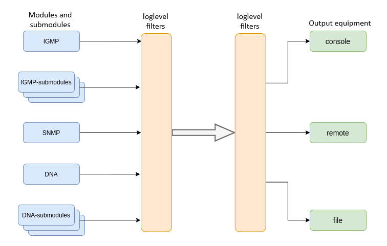
Figure 23 – Terminal system log
Messages of the system log are grouped into modules according to their functions. Configuration of the following modules is possible:
Table 15 – System log modules
Module | Description |
|---|---|
cli | CLI module service messages |
snmp | Messages from the SNMP agent |
dna | Primary network module messages |
fsm-pon | PON state machine messages |
igmp | Messages from IGMP operation module |
logmgr | Log control module service messages |
usermgr | Log control module service messages |
| dhcp | Service messages by DHCP module |
| pppoe | Service messages by PPPoE module |
| lldp | Service messages by LLDP module |
For more flexible logging configuration, the level of filtering, as well as sub-module settings, can be selected for each module.
The filtering level sets the minimum importance level of the messages to be displayed in the log. The used filtering levels are listed in Table 16.
Table 16 – System log filtering levels
Level | Description |
|---|---|
critical | Critical events |
error | Operation errors |
warning | Warnings |
notice | Important events during normal operation. Default values for all modules |
info | Information messages |
debug | Debug messages |
The critical level is the maximum level, the debug level is the minimum one.
The log subsystem allows display of the terminal operation log on different devices. All output devices can be used simultaneously.
Table 17 – System log output devices
Output device | Name | Description |
|---|---|---|
System log | system | Log output to the system log allows viewing the operation log locally or using a remote syslog server. |
Console | console | Log output to console allows system messages to be visible as soon as they appear on the terminal connected to the Console port. |
| CLI sessions | rsh | Log output to CLI session allows system messages to be visible as soon as they appear in all CLI sessions connected via Telnet or SSH. |
File | file | Log output to a file allows system messages to be written directly to the file, which can be sent to support specialists for further analysis. |
The log is saved in non-volatile memory by default. The system has 3 log rotated files of 1M each.
Module configuration
Consider the configuration using the dna module and the ont sub-module, which is responsible for displaying logs for the ONT. Other modules have similar configuration process.
Step 1. Enter the logging view.
LTP-16N(configure)# logging
Step 2. Set the level of log display with the ONT index for which the logs will be displayed. To do this use the module dna <port-id>[/ont-id] loglevel command.
LTP-16N(config)(logging)# module dna interface ont 1/1 loglevel debug
Step 3. Apply the configuration by using the commit command.
LTP-16N(config)(logging)# do commit
Configuring the log storage
Use the following command to record logs to non-volatile memory:
LTP-16N(config)(logging)# permanent
If you enter "no" before the command, the logs will be recorded to RAM. In this case, the logs will be erased after reboot.
System log configuration
Step 1. Use the file size command to specify the memory size in bytes to be used for system log storage.
LTP-16N(config)(logging)# file size 30000
Step 2. If necessary, use the remote server ip command to specify the IP address of the remote SYSLOG server to be used to display system log.
LTP-16N(config)(logging)# remote server ip 192.168.1.43
Step 3. Configure the output devices by using the logging command.
Each output device may have its own filtering level or have the output disabled.
For example, display of debug messages to a file and to a remote service can be displayed.
LTP-16N(config)(logging)# remote loglevel debug
LTP-16N(config)(logging)# file loglevel debug
Step 5. Apply the configuration by using the commit command.
LTP-16N(config)(logging)# do commit
Step 6. To view SYSLOG configuration information, use the do show running-config logging command.
LTP-16N(config)(logging)# do show running-config logging
 logging
    module dna ont 1/1 loglevel debug
    permanent
    file size 30000
    file loglevel debug
    remote server ip 192.168.1.43
    remote loglevel debug
 exit
Viewing log of configuration application
At the device start, a log of the startup configuration is saved. To view this log use the show log startup-config command.
LTP-16N# show log startup-config
(null)configure terminal
(null)interface front-port 1
(null)vlan allow 3470
(null)exit
(null)exit
(null)commit
To view log of application of downloaded backup configuration, use the show log backup-config command.
LTP-16N# show log backup-config

LTP-16N# configure terminal
LTP-16N# interface front-port 1
LTP-16N# vlan allow 3470
LTP-16N# exit
LTP-16N# exit
LTP-16N# commit
LTP-16N# exit
Viewing list of coredump files
If the main processes on the device crash, an archive is created with the Backtrace of the crash, logs and device configuration at the time of the crash. Data is stored to SSD and is available after device reboot. To view archive list, use the show coredump list command.
LTP-16N# show coredump list
##    Name                                                           Size               Date
---   ------------------------------------------------------------   ----------------   -------------------------
  1   /data/crash/ZMQbg!IO!0_2023-01-31_15-25-13.tar.gz                       5066744         31-01-2023 15:25:13
ALARMD configuration
ALARMD is a terminal alarms manager. Alarms manager enables troubleshooting and provides information about important events related to terminal operation.
A record in active alarms log (an event) corresponds to an event, which happened in the terminal. Types of events and their descriptions are provided in the following table.
Table 18 – Types of events in the active alarms log
Event | Description | Threshold |
|---|---|---|
system-ram | Free RAM size decreased to threshold value | 12% 1 |
| system-disk-space | Disk space size has reached threshold value | 10 1 |
| system-power-supply | Notification on power supply alarm | - |
system-login | User tried to log in or logged in using their credentials | - |
system-logout | User logged out | - |
system-load-average | Average CPU load reached the threshold, estimated time is 1 minute | 0 1 |
system-temperature | Temperature of one of the four temperature sensors has exceeded the threshold | 70 1 |
system-fan | Fan rotation speed exceeded the safe operating limits | 2000 < X < 12000 1 |
| config-save | User saved a configuration | - |
| config-save-failed | Configuration was not saved | - |
| config-change | OLT configuration was changed | - |
| config-rollback | Configuration was returned to initial running-config state | - |
pon-alarm-los | Translation of Loss of Signal PLOAM alarms | - |
| pon-alarm-losi | Translation of loss of a signal PLOAM alarms from PON port | - |
pon-alarm-lofi | Translation of Loss of Frame PLOAM alarms from ONT | - |
pon-alarm-loami | Translation of PLOAM loss PLOAM alarms from ONT | - |
pon-alarm-dowi | Translation of Drift of Window PLOAM alarms from ONT | - |
pon-alarm-sdi | Translation of Signal Degraded PLOAM alarms from ONT | - |
pon-alarm-sufi | Translation of Start-up Failure PLOAM alarms from ONT | - |
pon-alarm-loai | Translation of Loss of Acknowledge PLOAM alarms from ONT | - |
pon-alarm-dgi | Translation of Dying-Gasp PLOAM alarms from ONT | - |
pon-alarm-dfi | Translation of Deactivate Failure PLOAM alarms from ONT | - |
pon-alarm-tiwi | Translation of Transmission Interference Warning PLOAM alarms from ONT | - |
pon-alarm-loki | Translation of Loss of Key PLOAM alarms from ONT | - |
pon-alarm-lcdgi | Translation of Loss of GEM Channel Delineation PLOAM alarms from ONT | - |
pon-alarm-rdii | Translation of Remote Defect Indication PLOAM alarms from ONT | - |
| pon-port-state-change | Notification on PON port state change | - |
| pon-port-ont-count-overflow | Notification on ONT PON port counter overflow | - |
| transfer-file | Notification on file upload/download | - |
| olt-firmware-fail-update | Notification on OLT firmware update error | - |
| olt-firmware-update | Notification on OLT firmware update | - |
| ont-broadcast-storm | Notification on detection of ONT broadcasting storm | - |
| ont-config-change | ONT configuration change | - |
| ont-firmware-delete | Notification on ONT firmware file deletion | - |
| ont-firmware-update-complete | Notification on ONT firmware update completion | - |
| ont-firmware-update-progress | Notification on ONT firmware update being in progress | - |
| ont-firmware-update-start | Notification on ONT firmware update start | - |
| ont-firmware-update-stop | Notification on ONT firmware update stop | - |
| ont-link-down | Notification on ONT link being down | - |
| ont-link-up | Notification on ONT link being up | - |
| ont-multicast-storm | Notification on detection of ONT multicast storm | - |
| ont-rouge | Notification on detection rouge ONT | - |
| ont-no-config | Notification on absence of configuration for ONT | - |
| ont-state-changed | Notification on changing ONT state | - |
| ont-valid-config | Notification on valid ONT configuration | - |
1 The value can be adjusted.
Every record in the active alarms log has the parameters specified in Table 19 that are specified for each event type.
Table 19 – Parameters of events in the active alarms log
Token | Description |
|---|---|
severity | Describes event severity. Has four states:
|
in | Specifies whether an SNMP trap should be sent when an event is added to the log. Has two states:
|
out | Specifies whether an SNMP trap should be sent when an event is deleted from the log (normalization). Has two states: |
| ttl | Alarm lifetime in seconds. There are special options:
|
Active alarms log configuration
Step 1. To configure the active alarm log, enter the configure view and then to alarm view.
LTP-16N# configure terminal
LTP-16N(configure)# alarm
LTP-16N(config)(alarm)#
Step 2. For example, configure the alarm system-fan. To do this use the system-fan command. The other alarms are configured similarly.
LTP-16N(config)(alarm)# system-fan min-rpm 5000
LTP-16N(config)(alarm)# system-fan severity critical
LTP-16N(config)(alarm)# system-fan in true
Step 3. Apply the changes by using the do commit command.
LTP-16N(config)(alarm)# do commit
AAA configuration
This section describes the procedure for configuring services and protocols related to authentication, authorization, and accounting.
For AAA operation, RADIUS and TACACS+ protocols are supported. Table 15 lists these protocols functionality.
Table 20 – RADIUS and TACACS+ functionality
| Functionality and protocol | TACACS+ | RADIUS |
|---|---|---|
| Authentication | + | + |
| Authorization | + | - |
| CLI session start and end accounting (accounting start-stop) | + | - |
| CLI commands accounting (accounting commands) | + | - |
For supported protocols, server configuration principles are common. For each server, the following can be configured:
- IP address;
- key;
- timeout;
- port for connection to a server.
Up to 3 servers can be specified for RADIUS. They will be accessed according to the specified priority. If the priority is not specified, then the first priority, which is the highest, will be used by default.
Step 1. Configure RADIUS/TACACS+ server IP address and specify authentication and authorization via TACACS+. Authentication and authorization will be executed through the specified servers, the privilege level for the user is specified through the TACACS+ server.
LTP-16N# configure terminal
LTP-16N(configure)# aaa
LTP-16N(config)(aaa)# tacacs-server host 192.168.1.1
LTP-16N(config)(aaa)# tacacs-server host 192.168.1.2
LTP-16N(config)(aaa)# tacacs-server host 192.168.1.3
LTP-16N(config)(aaa)# authentication tacacs+
LTP-16N(config)(aaa)# authorization tacacs+ privilege
LTP-16N(config)(aaa)# enable
Step 2. Set the encryption key used when communicating with the server.
LTP-16N(config)(aaa)# tacacs-server host 192.168.1.1 key 1234567-r0
LTP-16N(config)(aaa)# tacacs-server host 192.168.1.2 key 1234567-r1
LTP-16N(config)(aaa)# tacacs-server host 192.168.1.3 key 1234567-r2
Step 3. Set the time to wait for the server to respond.
LTP-16N(config)(aaa)# tacacs-server timeout 3
Step 4. Set the port to use to connect to the server (if necessary).
LTP-16N(config)(aaa)# tacacs-server host 192.168.1.2 port 444
Step 5. Apply changes.
LTP-16N(config)(aaa)# do commit
VLAN configuration
This section describes VLAN configuration.
VLAN (Virtual Local Area Network) is a group of devices, which communicate on the channel level and are combined into a virtual network, connected to one or more network devices (GPON terminals or switches). VLAN is a very important tool for creating a flexible and configurable logical network topology over the physical topology of a GPON network.
Step 1. To configure VLAN, enter the configure view.
LTP-16N# configure terminal
LTP-16N(configure)#
Step 2. Enter the VLAN configuration mode with the vlan command. Pass VID as a parameter.
LTP-16N(configure)# vlan 5
LTP-16N(config)(vlan-5)#
VLAN configuration
To configure VLAN permission on interfaces, see Interface configuration.
Step 1. For convenience, specify a VLAN name by using the name command. To clear the name, use the no name command.
LTP-16N(config)(vlan-5)# name IpTV
Step 2. If you need to process IGMP packets on a specified VLAN, use the ip igmp snooping enable command to enable IGMP-snooping.
LTP-16N(config)(vlan-5)# ip igmp snooping enable
Step 3. Configure the IGMP querier if needed. It can be enabled with the help of the ip igmp snooping querier enable command.
The fast-leave mode is enabled by means of the ip igmp snooping querier fast-leave command. By default, this mode is disabled.
DSCP and 802.1P marking for IGMP query is configured by means of the ip igmp snooping querier user-prio and ip igmp snooping querier dscp commands.LTP-16N(config)(vlan-5)# ip igmp snooping querier enable LTP-16N(config)(vlan-5)# ip igmp snooping querier fast-leave LTP-16N(config)(vlan-5)# ip igmp snooping querier dscp 40
Step 4. Configure IGMP if needed.
Compatible versions (v1, v2, v3, or their combination):
LTP-16N(config)(vlan-5)# ip igmp version v2-v3
Interval between queries:
LTP-16N(config)(vlan-5)# ip igmp query-interval 125
Maximum query response time:
LTP-16N(config)(vlan-5)# ip igmp query-response-interval 10
Interval between Group-Specific Queries:
LTP-16N(config)(vlan-5)# ip igmp last-member-query-interval 1
Robustness:
LTP-16N(config)(vlan-5)# ip igmp robustness 2
Step 5. If necessary, set host/mrouter/learning mode for front-port. Mode is set with the ip igmp snooping front-port <N> mode command front-port and ip igmp snooping pon-port <N> mode command for pon-port.
LTP-16N(config)(vlan-5)# ip igmp snooping front-port 1 mode learning
Step 6. Apply the configuration by using the commit command.
LTP-16N(config)(vlan-5)# do commit
VLAN deletion
Step 1. Delete a VLAN by using the no vlan command. Pass VID (or its range) as a parameter.
LTP-16N(configure)# no vlan 5
Step 2. Apply the configuration by using the commit command.
LTP-16N(configure)# do commit
Port isolation configuration
Port isolation is a functionality that limits packets transmission between specific ports. Isolation group in which traffic passing can be allowed or denied between specific ports is configured on the device. All interfaces in isolation group are destination interfaces. Source interface is specified when assigning isolation group on VLAN which traffic needs to be denied.
Isolation group configuration
Step 1. Enter the configure view to configure isolation group.
LTP-16N# configure terminal
LTP-16N(configure)#
Step 2. Enter the isolation group configuration mode. Set isolation group number as a parameter.
LTP-16N(configure)# isolation group 1
LTP-16N(config)(isolation-group-1)#
Step 3. Allow traffic passing through needed interfaces.
LTP-16N(config)(isolation-group-1)# allow pon-port 1,2
Step 4. Apply configuration with the commit command.
LTP-16N(config)(isolation-group-1)# do commit
Step 5. If necessary, check isolation group settings.
LTP-16N# show isolation group 2
Step 6. By default 30 isolation groups are added to configuration and traffic to all interfaces is denied. If necessary, check settings of all isolation groups including default configuration.
LTP-16N# show running-config isolation all
Assigning isolation group to VLAN
Step 1. Assign isolation group created in previous steps to vlan. Enter the configure view for its configuration.
LTP-16N# configure terminal
LTP-16N(configure)#
Step 2. Enter VLAN configuration mode with the vlan command. Set VID as a parameter.
LTP-16N(configure)# vlan 5
LTP-16N(config)(vlan-5)#
Step 3. Assign isolation group and specify source interface.
LTP-16N(config)(vlan-5)# isolation assign group 1 to front-port 1
Step 4. Enable isolation.
LTP-16N(config)(vlan-5)# isolation enable
Step 5. Apply configuration with the commit command.
LTP-16N(config)(isolation-group-1)# do commit
Step 6. If necessary, check isolation settings on vlan.
LTP-16N# show isolation vlan 5
MAC age-time configuration
Step 1. Specify MAC addresses lifetime. Set value in seconds as a parameter.
LTP-16N(configure)# mac age-time 300
Step 2. Apply configuration with the commit command.
LTP-16N(configure)# do commit
MAC address lifetime is 6 cycles, each cycle starts depending on mac age-time settings and is equal to <age-time>/6.
If the MAC address is learned between cycles, then its lifetime will be in the range: from <age-time> - <age-time>/6 to <age-time>. For example, if MAC address lifetime is configured to be 600 seconds, then it will be from 500 to 600 seconds.
When the MAC address lifetime expires, one MAC address is deleted in 16 ms, meaning a maximum of 60 MAC addresses will be deleted per second.
CLI configuration
This section describes general CLI configuration procedure.
Configuring CLI session timeout
Step 1. Enter the configure view for global CLI configuration.
LTP-16N# configure terminal
LTP-16N(configure)#
Step 2. Set timeout value.
LTP-16N(configure)# cli timeout 1800
Step 3. Apply configuration with the commit command.
LTP-16N(configure)# do commit
Configuration of serial ONT display format
Step 1. Enter the configure view for global CLI configuration.
LTP-16N# configure terminal
LTP-16N(configure)#
Step 2. Set serial ONT display format.
LTP-16N(configure)# system ont-sn-format literal
Step 3. Apply configuration with the commit command.
LTP-16N(configure)# do commit
Starting with firmware version 1.6.3, old format of cli ont-sn-format literal command is out of date. If an outdated command format was used before the update, it will be automatically converted to new format.
Configuration of maximum number of CLI sessions
Step 1. Enter the configure view for global CLI configuration.
LTP-16N# configure terminal
LTP-16N(configure)#
Step 2. Set maximum number of simultaneous sessions.
LTP-16N(configure)# cli max-sessions 5
Step 3. Apply configuration with the commit command.
LTP-16N(configure)# do commit
IGMP configuration
This section describes general IGMP configuration.
Enabling snooping
Step 1. The global snooping configuration is performed in the configure view.
LTP-16N# configure terminal
LTP-16N(configure)#
Step 2. Enable IGMP snooping by using the ip igmp snooping command.
LTP-16N(configure)# ip igmp snooping enable
Step 3. Apply the configuration by using the commit command.
LTP-16N(configure)# do commit
Report proxying
Step 1. Proxying is configured in configure view.
LTP-16N# configure terminal
LTP-16N(configure)#
Step 2. Enable IGMP report proxying between VLAN by the ip igmp proxy report enable command.
LTP-16N(configure)# ip igmp proxy report enable
Step 3. Set IGMP report proxying rules by the ip igmp proxy report range command. As parameters, specify the range of allowed groups, as well as the direction of proxying as a pair of VIDs. It is possible to set general proxy rules for all VLANs. Use the from all keyword for this purpose.
LTP-16N(configure)# ip igmp proxy report range 224.0.0.1 226.255.255.255 from 30 to 90
Step 4. Apply the configuration by using the commit command.
LTP-16N(configure)# do commit
IGMP Proxy cannot be enabled without specifying a proxy range. Both settings are required.
DHCP configuration
This section describes the procedure for operating the terminal with the DHCP. The operation of the protocol can be divided into blocks:
- DHCP snooping. Used to intercept DHCP traffic, control and monitor sessions.
- DHCP opt82. Functionality to insert service option 82 in DHCP packets.
- DHCP relay. Functionality to redirect DHCP to another subnet.
DHCP snooping
This functionality is used to intercept and process traffic on the terminal CPU.
Currently, this functionality must be enabled if you want to control and monitor DHCP sessions and to operate with option 82 in DHCP packets.
DHCP snooping enabling
Step 1. The global snooping configuration is performed in the ip dhcp view, section configure view.
LTP-16N# configure terminal
LTP-16N(configure)# ip dhcp
LTP-16N(config)(dhcp)#
Step 2. Enable DHCP snooping using the snooping enable command.
LTP-16N(config)(dhcp)# snooping enable
DHCP option 82
DHCP option 82 is used to provide a DHCP server with additional information about a received DHCP request. This may include information about the terminal running DHCP option 82 as well as information about the ONT which sent the DHCP request. DHCP packets are modified by interception and further processing in the terminal CPU, i.e. DHCP snooping must be enabled.
The DHCP server analyses DHCP option 82 and identifies the ONT. Terminal allows the option to be both transparently transmitted from the ONT and formed/rewritten according to a specified format. DHCP option 82 is especially useful for networks, which have no private VLANs dedicated for each user.
DHCP option 82 supports configurable formats for both Circuit ID and Remote ID. The format of the suboptions is configured with the help of the tokens listed in Table 21. The listed service words will be replaced with their meanings, the rest of the text specified in the format field will be transmitted unchanged.
Table 21 – List of tokens for configuring the DHCP option 82 suboption format
Token | Description |
|---|---|
%HOSTNAME% | Terminal network name |
%MNGIP% | Terminal IP address |
%GPON-PORT% | Number of the OLT channel the DHCP request arrived from |
%ONTID% | ID of the ONT, which sent the DHCP request |
%PONSERIAL% | Serial number of the ONT, which sent the DHCP request |
%GEMID% | ID of the GEM port the DHCP request arrived to |
%VLAN0% | External VID |
%VLAN1% | Internal VID |
%MAC% | MAC address of the ONT, which sent the request |
%OLTMAC% | OLT`s MAC address |
%OPT60% | DHCP option 60 received from the ONT |
%OPT82_CID% | Circuit ID received from the ONT |
%OPT82_RID% | Remote ID received from the ONT |
%DESCR% | First 20 characters of ONT description |
DHCP option 82 management
The DHCP option 82 is configured via the profile system – profile dhcp-opt82. The system allows creating several different profiles and assigning them not only globally to all DHCP packets in general, but also separating profiles by VLAN.
Step 1.Create DHCP option 82 profile using the profile dhcp-opt82 command. Pass profile name as a parameter.
LTP-16N# configure terminal
LTP-16N(configure)# profile dhcp-opt82 test
LTP-16N(config)(profile-dhcp-opt82-test)#
Step 2. Assign the global profile, using the opt82 profile command in ip dhcp view.
LTP-16N(configure)# ip dhcp
LTP-16N(config)(dhcp)# opt82 profile test
Step 3. Assign another profile to the VLAN if needed.
LTP-16N(config)(dhcp)# opt82 profile test_vlan_100 vid 100
Step 4. Enable DHCP packet capture using the snooping enable command.
LTP-16N(config)(dhcp)# snooping enable
Step 5. Apply the configuration using the commit command.
LTP-16N(config)(dhcp)# do commit
DHCP option 82 profile configuration
Step 1. Create or switch to dhcp-opt82 profile.
LTP-16N# configure terminal
LTP-16N(configure)# profile dhcp-opt82 test
LTP-16N(config)(profile-dhcp-opt82-test)#
Step 2. Enable insert/overwrite of DHCP option 82 with the help of the overwrite-opt82 command if needed.
LTP-16N(config)(profile-dhcp-opt82-test)# overwrite-opt82 enable
Step 3. Set the DHCP option 82 format with the circuit-id and remote-id commands if necessary. A list of possible tokens is given in Table 15.
LTP-16N(config)(profile-dhcp-opt82-test)# circuit-id format %PONSERIAL%/%ONTID%
LTP-16N(config)(profile-dhcp-opt82-test)# remote-id format %OPT82_RID%
Step 4. Apply the configuration by using the commit command.
LTP-16N(config)(dhcp)# do commit
DHCP relay
The DHCP relay functionality is a relay of DHCP packets from a client network through a routed network to a DHCP server.
There are two configuration options. In one case, the DHCP server is in one VLAN with OLT management, in the other in different VLANs. Broadcast DHCP requests from the client VLAN will be transferred to the OLT management VLAN or to a separate VLAN (depending on configuration) and sent as unicast. Below are examples of both cases configuration.
DHCP Relay configuration in case when DHCP server is in OLT management VLAN
Step 1. Go to DHCP settings.
LTP-16N# configure terminal
LTP-16N(configure)#
LTP-16N(configure)# ip dhcp
LTP-16N(config)(dhcp)#
Step 2. Enable DHCP snooping. Snooping can be activated for all VLANs or for the necessary ones. In case with relay, it should be client (100) and management (200) VLAN.
LTP-16N(config)(dhcp)# snooping enable vlan 100,200
Step 3. Enable DHCP relay.
LTP-16N(config)(dhcp)# relay enable
Step 4. Specify servers address and client VLAN, from which the redirect will take place. Several servers can be specified, then redirection will be made to all servers at once, but the session will be built only through the first to respond.
LTP-16N(config)(dhcp)# relay server-ip 192.168.200.5 vid 100
LTP-16N(config)(dhcp)# relay server-ip 192.168.200.200 vid 100
Step 5. Apply the configuration with the commit command.
LTP-16N(config)(dhcp)# do commit
DHCP relay configuration, in case when DHCP server is in separate VLAN
Step 1. Go to DHCP settings.
LTP-16N# configure terminal
LTP-16N(configure)#
LTP-16N(configure)# ip dhcp
LTP-16N(config)(dhcp)#
Step 2. Enable DHCP snooping. Snooping can be activated for all VLANs or for the necessary ones. In case with relay, it should be client (100) and VLAN where DHCP server (300) is located.
LTP-16N(config)(dhcp)# snooping enable vlan 100,300
Step 3. Enable DHCP relay.
LTP-16N(config)(dhcp)# relay enable
Step 4. Specify servers address and client VLAN, from which the redirect will take place. Several servers can be specified, then redirection will be made to all servers at once, but the session will be built only through the first to respond.
LTP-16N(config)(dhcp)# relay server-ip 10.10.10.1 vid 100
LTP-16N(config)(dhcp)# relay server-ip 10.10.10.2 vid 100
Step 5. Configure address for the interface from which DHCP server will be accessed.
LTP-16N(config)(dhcp)# exit
LTP-16N(configure)# vlan 200
LTP-16N(config)(vlan-200)# ip interface address 192.168.200.1 mask 255.255.255.0
Step 6. Configure route to server.
LTP-16N(config)(dhcp)# exit
LTP-16N(configure)# ip route address 10.10.10.0 mask 255.255.255.0 gateway 192.168.200.2 name dhcp_server
Step 7. Apply the configuration with the commit command.
LTP-16N(config)(dhcp)# do commit
Active DHCP leases monitoring
When enabled, DHCP snooping allows monitoring of DHCP leases. To view the list of sessions use the show ip dhcp sessions command:
LTP-16N# show ip dhcp sessions
    DHCP sessions (2):
##     Serial         GPON-port   ONT-ID   Service   IP                MAC                 Vid   GEM    Life time
----   ------------   ---------   ------   -------   ---------------   -----------------   ---   ----   ---------
1      ELTX6C000090   1           1        1         192.168.101.75    E0:D9:E3:6A:28:F0   100   129    3503
2      ELTX71000030   1           3        1         192.168.101.143   70:8B:CD:BD:A5:32   100   189    3597
LTP-16N#
PPPoE configuration
This section describes the terminal operating procedure with the PPPoE. The operation of the protocol can be divided into two blocks:
- PPPoE snooping. Used to intercept PPPoE traffic, control and monitor PPPoE sessions.
- PPPoE intermediate agent. Functionality for inserting service information into PPPoE packets.
PPPoE snooping
This functionality is used to intercept and process traffic on the terminal CPU.
Currently, this functionality must be enabled if you want to control and monitor PPPoE sessions and to operate with option 82 in packets.
PPPoE snooping enabling
Step 1. The global snooping configuration is performed in the ip pppoe view, which in turn is in the configure view.
LTP-16N# configure terminal
LTP-16N(configure)# ip pppoe
LTP-16N(config)(pppoe)#
Step 2. Enable PPPoE snooping using the snooping enable command.
LTP-16N(config)(pppoe)# snooping enable
PPPoE intermediate agent
PPPoE Intermediate Agent is used to provide BRAS with additional information about a received PADI request. This may include information about the terminal running PPPoE Intermediate Agent as well as information about the ONT, which sent the PADI request. PADI packets are modified by interception and further processing in the terminal CPU.
BRAS analyses the Vendor Specific tag and identifies the ONT. PPPoE Intermediate Agent forms or rewrites the Vendor Specific tag using a specified format. Vendor Specific tags are especially useful for networks, which have no private VLANs dedicated for each user. PPPoE Intermediate Agent supports configurable formats for Circuit ID and Remote ID. The format of the suboptions is configured with the help of the tokens listed in Table 22. The listed service words will be replaced with their meanings, the rest of the text specified in the format field will be transmitted unchanged.
Table 22 – List of tokens to configure the PPPoE Intermediate Agent suboption format
Token | Description |
|---|---|
%HOSTNAME% | Terminal network name |
%MNGIP% | Terminal IP address |
%GPON-PORT% | Number of the OLT channel the PADI request arrived from |
%ONTID% | ID of the ONT, which sent the PADI request |
%PONSERIAL% | Serial number of the ONT, which sent the PADI |
%GEMID% | ID of the GEM port the PADI request arrived to |
%VLAN0% | External VID |
%VLAN1% | Internal VID |
%MAC% | MAC address of the ONT, which sent the request |
%OLTMAC% | MAC address of the OLT |
%DESCR% | First 20 characters of ONT description |
PPPoE Intermediate Agent management
The PPPoE Intermediate Agent is configured through the profile system – profile pppoe-ia. The system allows creating several different profiles and assign them globally to all PPPoE traffic.
Step 1. Create the PPPoE Intermediate Agent profile using the profile pppoe-ia command. Pass profile name as a parameter.
LTP-16N# configure terminal
LTP-16N(configure)# profile pppoe-ia test
LTP-16N(config)(profile-pppoe-ia-test)#
Step 2. Assign the global profile using the pppoe-ia profile command in ip pppoe view.
LTP-16N(configure)# ip pppoe
LTP-16N(config)(pppoe)# pppoe-ia profile test
LTP-16N(config)(pppoe)#
Step 3. Enable PPPoE packet capture using the snooping enable command.
LTP-16N(config)(pppoe)# snooping enable
Step 4. Apply the configuration using the commit command.
LTP-16N(config)(pppoe)# do commit
PPPoE Intermediate Agent profile configuration
Step 1. Create or switch to pppoe-ia profile.
LTP-16N# configure terminal
LTP-16N(configure)# profile pppoe-ia test
LTP-16N(config)(profile-pppoe-ia-test)#
Step 2. Set the PPPoE Intermediate Agent format with the circuit-id and remote-id commands if necessary. A list of possible tokens is given in Table 22.
LTP-16N(config)(profile-pppoe-ia-test)# circuit-id format %PONSERIAL%/%ONTID%
LTP-16N(config)(profile-pppoe-ia-test)# remote-id format %GEMID%
Step 3. Apply configuration with the commit command.
LTP-16N(config)(pppoe-ia)# do commit
Active PPPoE sessions monitoring
When PPPoE snooping is enabled, sessions can be monitored. To view the list of sessions use the show ip pppoe sessions command:
LTP-16N(config)(pppoe)# do show ip pppoe sessions
   PPPoE sessions (1):
##     Serial         GPON-port   ONT ID   GEM    Client MAC          Session ID   Duration    Unblock
----   ------------   ---------   ------   ----   -----------------   ----------   ---------   ---------
1      ELTX6C000090           1        1    129   E0:D9:E3:6A:28:F0       0x0001     0:06:00     0:00:00
Interface configuration
This section describes configuration of terminal interfaces.
Terminal interfaces can be divided into three groups:
- front-ports – to connect the OLT to the operator's core network;
GPON-ports – to connect ONT;
OOB – to manage and configure the OLT.
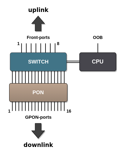
Figure 24 – Set of terminal interfaces
Table 23 – Interfaces types and numbers for LTP-8(16)N(T)
Interface | Number | Range |
|---|---|---|
front-port | 8 (for LTP-16N) 4 (for LTP-8N) | [1..8] [1..4] |
pon-port | 8 (for LTP-8N) 16 (for LTP-8N(T)) | [1..8] [1..16] |
oob | 1 | - |
Table 24 – Interfaces types and numbers for LTX-8(16)
| Interface | Number | Range |
|---|---|---|
| front-port | 4 | [1..4] |
| pon-port | 8 (for LTX-8) 16 (for LTX-16) | [1..8] [1..16] |
| oob | 1 | - |
front-ports configuration
Step 1. Enter the view of the interface (of interface group) settings of which to be changed.
LTP-16N# configure terminal
LTP-16N(configure)# interface front-port 1
LTP-16N(config)(if-front-1)#
Step 2. Enable the interface with the no shutdown command. The shutdown command disables the interface.
LTP-16N(config)(if-front-1)# no shutdown
Step 3. Set the list of allowed VLANs on the port, using the vlan allow command.
LTP-16N(config)(if-front-1)# vlan allow 100,200,300
Step 4. If necessary, change switchport mode. Three modes are supported:
- general – tagged traffic is processed in accordance with vlan allow rules, untagged traffic is marked as pvid;
- trunk – port receives/transmits only tagged traffic;
- access – access ports, only untagged traffic.
LTP-16N(config)(if-front-1)# switchport mode access
When selecting switchport mode access, it is necessary to remove allowed vlans on the port with the no vlan allow 1-4094 command.
Step 5. If necessary, change pvid. It will be used to mark all untagged traffic coming to an interface. By default, pvid = 1.
LTP-16N(config)(if-front-1)# pvid 1234
Step 6. Apply configuration with the commit command.
LTP-16N(config)(if-front-1)# do commit
PON interfaces configuration
Step 1. Enter the view of the interface (of interface group), which settings should be changed.
LTP-16N# configure terminal
LTP-16N(configure)# interface pon-port 13
LTP-16N(config)(if-pon-13)#
Step 2. If necessary, enable or disable encryption with the encryption or no encryption respectively.
LTP-16N(config)(if-pon-13)# encryption
Step 3. If necessary, set exchange interval between OLT and ONU keys in minutes with the encryption key-exchange interval command.
LTP-16N(config)(if-pon-13)# encryption key-exchange interval 5
Step 4. If necessary, enable or disable interfaces with the no shutdown or shutdown command.
LTP-16N(config)(if-pon-13)# shutdown
Step 5. If necessary, enable rogue ONT blocking.
LTP-16N(config)(if-pon-13)# block-rogue-ont enable
Step 6. If necessary, enable forward error correction in downstream direction.
LTP-16N(config)(if-pon-13)# fec
For LTX-8(16) FEC is enabled by default.
Step 7. If necessary, set length of the optical line in kilometers with the range command.
LTP-16N(config)(if-pon-13)# range 40
Step 8. Apply configuration with the commit command.
LTP-16N(config)(if-pon-13)# do commit
Pon-type configuration
For LTX-8(16) it is possible to configure the operating mode of the pon-port using GPON or XGS-PON technology. By default, XGS-PON mode is used. If it is necessary to change the mode, do the following:
Step 1. Change operation mode to GPON:
LTX-16# configure
LTX-16(config)# interface pon-port 1
LTX-16(config)(if-pon-1)# pon-type gpon
Step 2. Apply configuration with the commit command.
LTX-16(config)(if-pon-1)# do commit
When changing pon-type, the terminal will be automatically reconfigured. It will cause a temporary suspension of services, including access to the OLT.
OOB port configuration
Step 1. Check current network parameters with the show running-config interface port-oob command.
LTP-16N# show running-config interface port-oob all
 interface port-oob
    description ""
    speed auto
    no shutdown
    ip 192.168.100.2 mask 255.255.255.0 vid 1
    no include management
 exit
Step 2. Go to interface view.
LTP-16N# configure terminal
LTP-16N(configure)# interface port-oob
LTP-16N(config)(if-port-oob)#
Step 3. Specify IP address, mask, VLAN of OOB interface with the ip <IP> mask <IP> vid <VLAN> command.
LTP-16N# configure terminal
LTP-16N(configure)# interface port-oob
LTP-16N(config)(if-port-oob)# ip 192.168.100.3 mask 255.255.255.0 vid 1111
Step 4. If necessary, enable OOB interface in management bridge.
LTP-16N# configure terminal
LTP-16N(configure)# interface port-oob
LTP-16N(config)(if-port-oob)# include management
Simultaneous connection to OOB and an uplink port in the management VLAN may cause a loop.
To exclude OOB interface from management bridge (set the no include management value for OOB port configuration), ensure there is no overlap between the OOB port subnet and the management and ACS subnets. Additionally, their VLANs should not match. These values are checked during configuration application (commit).
Step 5. If necessary, enable or disable interfaces with the no shutdown or shutdown command.
LTP-16N(config)(if-port-oob)# shutdown
Step 6. Apply configuration with the commit command.
LTP-16N(config)(if-port-oob)# do commit
Local switching configuration (bridging in VLAN)
By default, traffic transmission is allowed only between front-ports and pon-ports. Front-port interfaces are isolated are isolated from each other, as well as pon-port interfaces. Allow traffic transmission between front-ports interfaces, as well as between pon-ports interfaces in specific VLAN, with the bridge allow command. The configuration must be done symmetrically on those interfaces between which traffic transmission must be allowed.
Front-port configuration
Step 1. To allow traffic passing between front-ports in specified VLANs, go to front-port interface (of group of interfaces) view, which needs to be reconfigured.
LTP-16N# configure terminal
LTP-16N(configure)# interface front-port 1,5
LTP-16N(config)(if-front-1,5)#
Step 2. Specify list of bridges allowed on port with the bridge allow command.
LTP-16N(config)(if-front-1,5)# bridge allow 100,200,300
Step 3. Apply configuration with the commit command.
LTP-16N(config)(if-front-1,5)# do commit
Pon-port configuration
Bridging between pon-ports 1 and 5 is configured similarly to front-ports.
Step 1. To allow traffic passing between pon-ports in specified VLANs, go to pon-port interface (of group of interfaces) view, which needs to be reconfigured.
LTP-16N# configure terminal
LTP-16N(configure)# interface pon-port 1,5
LTP-16N(config)(if-pon-1,5)#
Step 2. Specify list of bridges allowed on port with the bridge allow command.
LTP-16N(config)(if-pon-1,5)# bridge allow 500,600
Step 3. Apply configuration with the commit command.
LTP-16N(config)(if-pon-1,5)# do commit
For bridge operation between pon-ports, ONTs should be configured according to 1-to-1 service model.To allow traffic transmission between ONTs on one pon-port, it is enough to configure bridge on this port and to enable arp-proxy enable on the same port.
For bridge operation between front-ports, VLAN should be allowed on these ports with the vlan allow command.
Maximum number of VLANs in which it is possible to enable bridging on port is equal to 10.
LAG configuration
This section describes configuration of uplink interfaces aggregation. Link aggregation (IEEE 802.3ad) is a technology that allows multiple physical links to be combined into one logical link (aggregation group). Aggregation group has a higher throughput and is very reliable.
The terminal supports static and dynamic modes of interface aggregation. In static mode (default) all communication channels in the group are always active.
Dynamic aggregation mode using the LACP (Link Aggregation Control Protocol) allows configuring active or passive methods for each port to negotiate connection parameters with a neighboring device.
Port-channel configuration
Step 1. Create port-channel interface and use the index as a parameter.
LTP-16N# configure terminal
LTP-16N(configure)# interface port-channel 1
LTP-16N(config)(if-port-channel-1)#
Step 2. The port-channel settings are mostly similar to the front-port settings. For example, VLANs passing can be allowed:
LTP-16N(config)(if-port-channel-1)# vlan allow 100,200,300
Step 3. Apply configuration with the commit command.
LTP-16N(config)(if-port-channel-1)# do commit
Adding ports to port-channel
Step 1.To aggregate ports in a port-channel, go to the ports to be aggregated:
LTP-16N(configure)# interface front-port 3-4
LTP-16N(config)(if-front-3-4)#
Step 2. Set the port-channel on the interfaces using the channel-group command.
LTP-16N(config)(if-front-3-4)# channel-group port-channel 1
Interface and port-channel configurations should be the same. If the configurations are different, an error will occur when trying to aggregate the interfaces. If you want to force the aggregation, you can use the force option for the channel-group command. In this case, the interfaces will be configured from the port-channel and the current configuration will be reset.
An interface can belong to only one aggregation group.
Step 3. Apply configuration with the commit command.
LTP-16N(config)(if-front-3-4)# do commit
LACP configuration
Step 1. If necessary, use dynamic settings, switch interface to LACP mode:
LTP-16N(configure)# interface port-channel 1
LTP-16N(config)(if-port-channel-1)# mode lacp
LTP-16N(config)(if-port-channel-1)# exit
LTP-16N(config) do commit
Front-port in aggregated group is set to mode active by default, i.e., it initiates negotiation of connection parameters with a neighboring device.Step 2. If necessary, set LACPDU packet sending interval from port every 30 seconds:
LTP-16N(configure)# interface front-port 3
LTP-16N(config)(if-front-3)# lacp rate slow
LTP-16N(config)(if-front-3)# do commit
Step 3. If necessary, configure front-port selection priority by changing global (general) settings and local (with a higher priority) port settings:
LTP-16N(configure)# lacp system-priority 1000
LTP-16N(configure)# interface front-port 3
LTP-16N(config)(if-front-3)# lacp port-priority 500
LTP-16N(config)(if-front-3)# do commit
Balancing configuration
It is possible to configure parameters for traffic balancing functions in port-channel. It is possible to configure the polynomial to be used in the interface selection function with the interface port-channel load-balance polynomial command. You can also configure which of the header fields will be used in calculations. Possible options: src-mac, dst-mac, vlan, ether-type. It is allowed to use a combination of up to 3 fields.
LTP-16N# configure terminal
LTP-16N(configure)# interface port-channel load-balance hash src-mac dst-mac vlan
LTP-16N(configure)# interface port-channel load-balance polynomial 0x9019
LLDP configuration
Link Layer Discovery Protocol (LLDP) — link layer protocol, which allows network devices advertising their identity, capabilities, as well as gathering this information about neighboring devices. There is support for standard RFC mib 1.0.8802 in SNMP agent.
Global LLDP configuration
Step 1. Global LLDP settings are located in configure view. Enter this section by using configure terminal command.
LTP-16N# configure terminal
LTP-16N(configure)#
Step 2. Enable LLDP processing by using lldp enable command. By default is disabled.
LTP-16N(configure)# lldp enable
Step 3. Specify how often the device will send LLDP information updates. By default 30 seconds.
LTP-16N(configure)# lldp timer 10
Step 4. Set the amount of time for the receiving device to hold received LLDP packets before dropping (by default 120 seconds). This value is sent to the received side in LLDP update packets and is a multiplicity for a LLDP timer (lldp timer). Thus, the lifetime of LLDP packets (Time-to-live) is calculated by the formula: TTL = min(65535, LLDP-Timer * LLDP-HoldMultiplier).
LTP-16N(configure)# lldp hold-multiplier 5
Step 5. If necessary, tx-delay interval, which controls the delay in sending LLDP advertisements triggered by changes in the LLDP MIB, can be changed. Default value is 2 seconds:
LTP-16N(configure)# lldp tx-delay 5
Step 6. If necessary, reinit interval, which defines waiting time after LLDP or port shutdown or when rebooting the switch before a new LLDP initialization. Default value is 2 seconds:
LTP-16N(configure)# lldp reinit 3
Step 7. Apply configuration with the commit command.
LTP-16N(configure)# do commit
LLDP configuration for interfaces
Step 1. Configuring LLDP on interfaces in corresponding interface-front-port view. Go to the interfaces section for which LLDP needs to be configured.
LTP-16N# configure terminal
LTP-16N(configure)# interface front-port 1-3
LTP-16N(config)(if-front-1-3)#
Step 2. Change the port operation mode from LLDP, if necessary.
LTP-16N(config)(if-front-1-3)# lldp mode transmit-receive
Step 3. Set optional TLV to be sent in LLDP:
LTP-16N(config)(if-front-1-3)# lldp optional-tlv port-description system-name
Step 4. If necessary, set specific TLV:
LTP-16N(config)(if-front-1-3)# lldp optional-tlv 802.1 management-vid system-name
LTP-16N(config)(if-front-1-3)# lldp optional-tlv 802.3 max-frame-size mac-phy
Step 5. Apply configuration with the commit command.
LTP-16N(config)(if-front-1-3)# do commit
Step 6. Check configuration with the show running-config interface front-port 1 command.
LTP-16N# show running-config interface front-port 1
 interface front-port 1
    lldp mode transmit-only
    lldp optional-tlv port-description
    lldp optional-tlv system-name
    lldp optional-tlv 802.1 management-vid
    lldp optional-tlv 802.3 max-frame-size
    lldp optional-tlv 802.3 mac-phy
 exit
IP source-guard configuration
IP source-guard allows limiting an unauthorized use of IP addresses on the network by binding source IP and MAC addresses to a specific service on a specific ONT. There are two operation modes:
Static – to pass any traffic from the client, explicitly set the IP and MAC addresses of the client equipment.
Dynamic – obtaining an address by client equipment via DHCP protocol. Based on the exchange of client equipment with the DHCP server, a DHCP snooping table containing the MAC-IP-GEM-port correspondence as well as information about the lease time is formed on the OLT. Only those packets from the client are allowed, in which the "MAC source" and "IP source" fields match the entries in the DHCP snooping table. To ensure the operation of client equipment, the IP address of which was set statically, it is possible to create static entries in dynamic mode.
For IP source-guard operation in dynamic mode, enable DHCP snooping on this VLAN. For more information, see the DHCP snooping section.
Step 1. Enable IP source-guard.
LTP-16N# configure terminal
LTP-16N(configure)#ip source-guard enable
The ip source-guard enable command enables agent operation for all VLANs. If IP source-guard operation is needed only in a certain VLAN, then enable the agent only for this VLAN.
LTP-16N(configure)#ip source-guard enable vlan 100
Step 2. Apply configuration with the commit command.
LTP-16N(configure)# do commit
The following command is used to enable a DHCP session to be re-established for a device with the same MAC address:
LTP-16N(configure)# ip source-guard one-dynamic-binding-for-mac enable
It will automatically overwrite an old session with a new one.
The following command is used to add static bindings:
LTP-16N(configure)# ip source-guard bind ip <IP> mac <MAC> interface-ont <ONT> service <NUM>
where:
- IP – IP address of client equipment in Х.Х.Х.Х format;
- MAC – MAC address of client equipment in ХХ:XX:XX:XX:XX:XX format;
- ONT – ONT ID in X/Y format (CNANNEL_ID/ONT_ID);
- NUM – service number on the ONT through which traffic with specified addresses in the range 1-30 will pass.
Use the show command to view status, mode, and static binding information:
LTP-16N# show ip source-guard binds
By default, the dynamic mode is used. Dynamic and static entries work simultaneously. If only static entries are needed, configure the following:
LTP-16N(configure)# ip source-guard mode static
IP arp-inspection configuration
ARP Inspection is meant for protection from attacks using ARP (for example, ARP-spoofing is interception of ARP traffic). ARP is managed based on IP and MAC address matches fixed dynamically or specified statically in the configuration.
Step 1. Enable IP arp-inspection.
LTP-16N# configure terminal
LTP-16N(configure)#ip arp-inspection enable
The ip arp-inspection enable command activates ARP requests compliance control for all VLANs. If IP arp-inspection operation is required only in specific VLANs, then enable agent with the VLAN specified.
LTP-16N(configure)#ip arp-inspection enable vlan 131
Step 2. Apply changes.
LTP-16N(configure)# do commit
For dynamic bindings, IP DHCP Snooping should be active in configurations.
To add static bindings, use the following commands:
LTP-16N(configure)# ip arp-inspection bind ip <IP> mac <MAC> interface-ont <ONT> service <NUM>
Where:
- IP – IP address of client equipment in Х.Х.Х.Х format;
- MAC – MAC address of client equipment in ХХ:XX:XX:XX:XX:XX format;
- ONT – ONT ID in X/Y format (CNANNEL_ID/ONT_ID);
- NUM – service number on the ONT through which traffic with specified addresses in the range 1-30 will pass.
To view information about state, static and dynamic bindings, use the show command:
LTP-16N# show ip arp-inspection
Port mirroring configuration
Port mirroring allows you to duplicate the traffic on monitored ports by forwarding incoming and/or outgoing packets to the controlling port. The user has the ability to set the controlling and controlled ports and select the type of traffic (inbound and/or outbound) that will be sent to the controlling port.
Mirroring configuration
Step 1. Port mirroring is performed in mirror view section. In total, up to 15 mirrors with a unique destination interface can be created. To enter the mirror view, run the command:
LTP-16N# configure terminal
LTP-16N(configure)# mirror 1
LTP-16N(config)(mirror-1)#
Step 2. Specify the interface to which the mirrored traffic will be sent. There can be only one interface for all created mirrors.
LTP-16N(config)(mirror-1)# destination interface front-port 1
Step 3. If necessary, an additional label for mirrored traffic can be set.
LTP-16N(config)(mirror-1)# destination interface front-port 1 add-tag 777
Step 4. Add ports from which traffic will be listened. If necessary to listen specific VLANs, add the vlan keyword to the command. If only one of the traffic directions needs to be listened to, add rx or tx.
LTP-16N(config)(mirror-1)# source interface pon-port 9
Step 5. Apply the configuration by using the commit command.
LTP-16N(config)(mirror-1)# do commit
Packets mirrored from the PON port will have an additional label. This label is equal to the value of the GEM port from which the packet was received.
QoS
QoS is currently supported only via IEEE 802.1p.
General QoS configuration
Step 1. QoS configuration is performed in configure view section.
LTP-16N# configure terminal
LTP-16N(configure)#
Step 2. Enable QoS processing according to priorities. By default, all packets are directed to 0, the non-priority queue.
LTP-16N(configure)# qos enable
Step 3. Select QoS operation mode. Currently only 802.1p is supported.
LTP-16N(configure)# qos type 802.1p
Step 4. Apply the configuration by using the commit command.
LTP-16N(configure)# do commit
After changing the QoS settings, the terminal will be automatically reconfigured. It will cause temporal stop of services.
For QoS operation in upstream, front port utilization should be at maximum since DBA algorithm operates in such a way that the pon port cannot receive more than 1.25 Gbps of traffic, i.e. there cannot be more throughput pon-port abilities.
L2 QoS configuration
Step 1. Select the queue scheduler operation mode:
- SP — Strict priority mode. Strict priority ensures packet processing according to queue priority.
- WFQ — Weighted Fair Queue. This mode focuses on the weights of each queue and their ratios. Packets are processed according to the weight of the queue.LTP-16N(configure)# qos 802.1p mode sp
Step 2. Use the qos map command to set the 802.1p translation rules to the appropriate queue:
LTP-16N(configure)# qos 802.1p map 0 to 1
Step 3. When using the WFQ mode, distribute the weights of each queue as necessary:
LTP-16N(configure)# qos 802.1p wfq queues-weight 10 23 11 40 0 63 2 60
Step 4. Apply configuration with the commit command.
LTP-16N(configure)# do commit
Weighted Fair Queue operates based on queue weight. For example, two queues with weights 10 and 20 are used. The bandwidth for these queues will be calculated using the following formula: (queue weight\(sum of queue weights). That is, in this example, the bandwidth will be divided into 10\30 and 20\30.
After changing the QoS settings, the terminal will be automatically reconfigured. It will cause temporal stop of services.
Access Control List configuration
ACL (Access Control List) is a table, which defines rules for filtering incoming traffic based on protocols, TCP/UDP ports, IP addresses or MAC addresses transmitted in packets. One access-list ip and one access-list mac can be assigned to one interface. Each access-list can contain up to 20 rules. By default, access-lists are created as black list.
Access-list MAC configuration
MAC access-list can be filtered by the following criteria and mask:
Table 25 — List of MAC access-list criteria
| Criterion | Mask | Command example | Note |
|---|---|---|---|
| Src MAC | yes | permit A8:F9:4B:00:00:00 FF:FF:FF:00:00:00 any | Mask 00:00:00:00:00:00 is equal to any Mask FF:FF:FF:00:00:00 corresponds to A8:F9:4B:00:00:00 - A8:F9:4B:FF:FF:FF addresses range Mask FF:FF:FF:FF:FF:FF corresponds to one specific address |
| Dst MAC | yes | permit any A8:F9:4B:00:00:00 FF:FF:FF:00:00:00 | |
| Vlan | no | permit any any vlan 10 | |
| COS | yes | permit any any vlan any cos 4 4 | Mask 0 is equal to any Mask 4(100) corresponds to cos 4(100), 5(101), 6(110), 7(111) Mask 7 corresponds to one specific cos |
| Ethertype | yes | permit any any vlan any cos any ethertype 0x0800 0xFF00 | Mask 0x0000 is equal to any Mask 0xFF00 corresponds to 0x0800 - 0x08FF range Mask 0xFFFF corresponds to one specific ethertype |
Step1. Create mac access-list.
LTP-16N# configure terminal
LTP-16N(configure)# access-list mac deny_mac
LTP-16N(config)(access-list-mac-deny_mac)#
Step 2. Configure the rules.
LTP-16N(config)(access-list-mac-deny_mac)# deny a8:f9:4b:aa:00:00 FF:FF:FF:FF:00:00 any
LTP-16N(config)(access-list-mac-deny_mac)# deny any a8:f9:4b:ff:24:86 FF:FF:FF:FF:00:00
LTP-16N(config)(access-list-mac-deny_mac)# deny any any vlan 10 cos 4 4
LTP-16N(config)(access-list-mac-deny_mac)# deny any any vlan any cos any ethertype 0xAB00 0xFFFF
LTP-16N(config)(access-list-mac-deny_mac)# exit
LTP-16N(config)# exit
LTP-16N# commit
Step 3. Check access list configuration.
LTP-16N# show running-config access-list
    access-list mac deny_mac
        deny A8:F9:4B:AA:00:00 FF:FF:FF:FF:00:00 any index 1
        deny any A8:F9:4B:FF:24:86 FF:FF:FF:FF:00:00 index 2
        deny any any vlan 10 cos 4 4 index 3
        deny any any ethertype 0xAB00 0xFFFF index 5
    exit
Step 4. Assign access-list to the port.
LTP-16N(config)# interface pon-port 3
LTP-16N(config)(if-pon-3)# access-list mac deny_mac
LTP-16N(config)(if-pon-3)# exit
LTP-16N(config)# exit
LTP-16N# commit
Step 5. Check access-list assignment to the port.
LTP-16N# show running-config interface pon-port 3
interface pon-port 3
access-list mac "deny_mac"
exit
LTP-16N#
To configure access-list as a white list, the rule must be as follows:
deny any any
Access-list IP configuration
IP access-list rules support criteria available at MAC access-list.
Table 26 — List of IP access-list criteria
| Criterion | Mask | Command example | Note |
|---|---|---|---|
| Proto ID | no | permit tcp ... permit udp ... permit any ... permit proto <id> ... | |
| Src IP | yes | permit any 10.10.0.0 255.0.255.0 any | Mask 0.0.0.0 is equal to any Mask 255.0.255.0 corresponds to 10.0.10.0 - 10.255.10.255 range Mask 255.255.255.255 corresponds to one specific address |
| Dst IP | yes | permit any any 10.10.0.0 255.0.255.0 | |
| DSCP | no | permit any any any dscp 48 | |
| Precedence | no | permit any any any precedence 7 | |
| Src MAC | yes | permit any any any dscp any mac A8:F9:4B:00:00:00 FF:FF:FF:00:00:00 any | Mask 00:00:00:00:00:00 is equal to any Mask FF:FF:FF:00:00:00 corresponds to A8:F9:4B:00:00:00 - A8:F9:4B:FF:FF:FF addresses range Mask FF:FF:FF:FF:FF:FF corresponds to one specific address |
| Dst MAC | yes | permit any any any dscp any mac any A8:F9:4B:00:00:00 FF:FF:FF:00:00:00 | |
| Vlan | no | permit any any any dscp any mac any any vlan 10 | |
| COS | yes | permit any any any dscp any mac any any vlan any cos 4 4 | Mask 0 is equal to any Mask 4(100) corresponds to cos 4(100), 5(101), 6(110), 7(111) Mask 7 corresponds to one specific cos |
| Ethertype | yes | permit any any any dscp any mac any any vlan any cos any ethertype 0x0800 0xFF00 | Mask 0x0000 is equal to any Mask 0xFF00 corresponds to 0x0800 - 0x08FF range Mask 0xFFFF corresponds to one specific ethertype |
Step 1. Create ip access-list.
LTP-16N# configure terminal
LTP-16N(configure)# access-list ip deny_ip
LTP-16N(config)(access-list-ip-deny_ip)#
Step 2. Configure the rules and assign access-list to port.
LTP-16N(config)(access-list-ip-deny_ip)# permit proto 1 any any
LTP-16N(config)(access-list-ip-deny_ip)# deny udp 10.4.5.0 255.255.255.0 any any any
LTP-16N(config)(access-list-ip-deny_ip)# deny udp any any 5.6.0.0 255.255.0.0 any
LTP-16N(config)(access-list-ip-deny_ip)# deny tcp any 4321 any any dscp 48
LTP-16N(config)(access-list-ip-deny_ip)# permit udp 3.3.3.3 255.255.255.255 80 7.7.7.7 255.255.255.255 82 dscp 63 mac A2:F9:4B:00:00:44 FF:FF:FF:FF:F0:00 FD:4B:2E:3A:FF:12 FF:FF:FF:FF:FF:FF vlan 12 cos 2 3 ethertype 0xAB00 0xFFFF
LTP-16N(config)(access-list-ip-deny_ip)# deny udp 3.3.3.3 255.255.255.255 any any any
LTP-16N(config)(access-list-ip-deny_ip)# exit
LTP-16N(configure)#
LTP-16N# commit
Step 3. Check access-list configuration.
LTP-16N# show running-config access-list
access-list ip deny_ip
permit proto 1 any any index 1
deny udp 10.4.5.0 255.255.255.0 any any any index 2
deny udp any any 5.6.0.0 255.255.0.0 any index 3
deny tcp any 4321 any any dscp 48 index 4
permit udp 3.3.3.3 255.255.255.255 80 7.7.7.7 255.255.255.255 82 dscp 63 mac A2:F9:4B:00:00:44 FF:FF:FF:FF:F0:00 FD:4B:2E:3A:FF:12 FF:FF:FF:FF:FF:FF vlan 12 cos 2 3 ethertype 0xAB00 0xFFFF index 5
deny udp 3.3.3.3 255.255.255.255 any any any index 6
exit
LTP-16N#
Step 4. Assign access-list to the port.
LTP-16N(config)# interface front-port 8
LTP-16N(config)(if-front-8)# access-list mac deny_ip
LTP-16N(config)(if-front-8)# exit
LTP-16N(config)# exit
LTP-16N# commit
Access-list rules editing and deleting
Step 1. Rule can be changed by entering a new line with the corresponding index.
LTP-16N(configure)# access-list ip deny_ip
LTP-16N(config)(access-list-ip-duip)# deny tcp any 4321 any any index 4
LTP-16N(config)(access-list-ip-duip)# do commit
Step 2. Specific rule can be deleted by using the remove command, specifying the index.
LTP-16N(config)(access-list-ip-duip)# remove index 4
LTP-16N(config)(access-list-ip-duip)# do commit
To configure access-list as a white list, the rule must be as follows:
deny any any any index 20
Access-list deleting
Step 1. To delete an access-list, delete it first from all interfaces to which this access-list is assigned.
LTP-16N(configure)# interface front-port 8
LTP-16N(config)(if-front-8)# no access-list ip
LTP-16N(config)(if-front-8)# exit
Step 2. Delete the access-list itself.
LTP-16N(configure)# no access-list ip deny_ip
LTP-16N(configure)# do commit
Configuration committed successfully
L3 interfaces configuration
OLT supports creating of up to 9 L3 interfaces (not including management). Interfaces created can be used to access OLT via Telnet/SSH/SNMP and for DHCP-relay operation via same.
Step 1. Assign IP address and IP mask to VLAN interface.
LTP-16N(configure)# vlan 100
LTP-16N(config)(vlan-100)# ip address 192.168.5.5 mask 255.255.255.0
LTP-16N(config)(vlan-100)# do commit
When creating L3 interface there should be no overlap of IP addresses with other OLT interfaces: management, oob, ACS, L3 interfaces. Also, the same addresses cannot be configured for several interfaces.
By default, access to OLT via created interface is closed.
Step 2. Open access via created interface:
LTP-16N(configure)# vlan 100
LTP-16N(config)(vlan-100)# ip interface management access allow
LTP-16N(config)(vlan-100)# do commit
Access configuration via Telnet/SSH/SNMP is the same for all L3 и management interfaces. For example, if access via Telnet is allowed for management, then it will be opened for L3 interfaces too.
Step 3. If necessary, configure the route:
LTP-16N(configure)# ip route address 10.10.10.10 mask 255.255.255.255 gateway 192.168.5.1 name test_route
LTP-16N(configure)# do commit
ONT configuration
Service models
This section considers main terms and classification of service models.
The service model can generally be based on one of the service principles: N-to-1, 1-to-1 and multicast. The "VLAN for Service" (N-to-1) architecture means that a service VLAN (S-VLAN) is used to provide all users with a certain service. The "VLAN for Subscriber" (1-to-1) architecture implies that a client VLAN (C-VLAN) is used to provide a user with multiple services. These methods are often combined in practice and form a hybrid model, which uses S-VLAN and C-VLAN simultaneously.
1-to-1 architecture
A separate VLAN is used for each subscriber in the C-VLAN model. In this operation scheme a channel from the uplink port to the GEM port of the ONT, in a given S-VLAN is built for the subscriber. And all traffic (including broadcast), goes to this GEM-port.
N-to-1 architecture
The S-VLAN model has dedicated S-VLANs for each service. Traffic is distributed among the GEM ports of the clients, based on the MAC table. If the MAC address is not learnt, the packet is sent to the broadcast GEM-port and replicated to all subscribers.
Multicast architecture
This architecture is similar to N-to-1, except that a dedicated multicast GEM port is used.
Operating principle
The model traffic concept is used for implementation of different service models in the terminal. The model is configured in a cross-connect profile, which allows the configuration of combined circuits within a single ONT. The detailed example is given below.
1-to-1
Below is an example of operation of the service configured according to the 1-to-1 model.
The diagram of this service model is shown in the Figure 25.
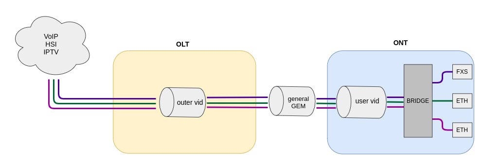
Figure 25 – 1-to-1 traffic model operation diagram
The 1-to-1 service model is a traffic model in which multiple services are delivered on a client VLAN that is separate for each user. A C-VLAN is used between an ONT and service routers (BRAS, VoIP SR) that encapsulate services for one subscriber, such as VoIP, Internet, and IPTV. Each service will use its own GEM port. This model is characterized by the absence of a dedicated broadcast GEM port, i.e. all broadcast traffic goes to the unicast GEM. Unicast traffic will be sent to the desired GEM port based on the MAC table.
Translation of traffic from each service in the client VLAN to the corresponding user VLANs is carried out on the OLT side. When a service request is received in the upstream direction, the MAC table is populated at the OLT according to the user VLAN. For service-specific downstream traffic, the GEM port is determined based on the OLT MAC table.
If in downstream direction the traffic comes with an unknown destination address (broadcast or unknown unicast), meaning the GEM port cannot be uniquely determined, then this traffic is transmitted by replicating the packet to all associated GEM service ports with corresponding translation to the specified user VLANs.
N-to-1
Below is an example of the implementation of a service model that falls under the N-to-1 structure. This scheme is best considered using the example of two ONTs.
The diagram of this model is shown in the Figure 26.
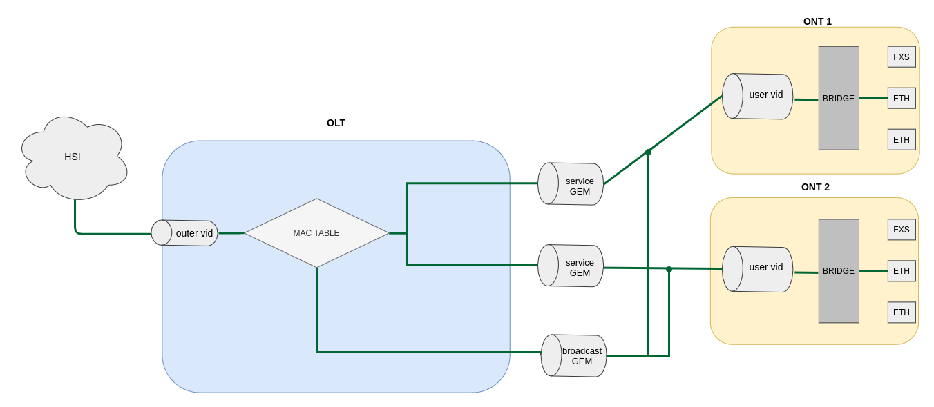
Figure 26 – N-to-1 model diagram
Dedicated S-VLANs are used between the OLT and service routers (BRAS, VoIP SR) for each of the following services (here – Internet). The destination of the packet is defined by the MAC table, which explicitly stores the MAC address and GEM port correspondence. If no entry is found, the packet is sent to the broadcast GEM port and replicated to all ONTs using the service.
Multicast
The multicast scheme is similar to the N-to-1 scheme, except that a multicast GEM port is used and the MAC table is involved only in IGMP exchange. Multicast is sent directly to the multicast GEM port. This mechanism is closely related to IGMP snooping.
VLAN ID replacement
The transfer of traffic from the service S-VLAN to the client C-VLAN can be done either on the OLT or on the ONT. To configure the replacement place, the vlan-replace option is used. The option is configured in the cross-connect profile, which allows configuring the label replacement scheme for each service. By default, the replacement occurs on ONT.
Only one replace-side can be used within one ONT.
ONT licensing
By default, only ONT manufactured by ELTEX Enterprise LLC is allowed to work on the OLT. To enable any third-party ONTs, OLT requires a license. To purchase the license, contact ELTEX Marketing Department.
Loading a license file to OLT
A license is a text file of the following format:
{
"version":"<VER>",
"type":"all",
"count":"<count>",
"sn":"<SN>",
"mac":"<MAC>",
"sign":"<hash>"
}
Where:
- VER – license file version number;
- count – number of third-party ONTs enabled on the OLT;
- SN – LTP serial number;
- MAC – LTP MAC address;
- hash – license file digital signature.
There are two ways to load a license to OLT.
- Use the copy command:
LTP-16N# copy tftp://<IP>/<PATH> fs://license
Download file from TFTP-server..
License successfully installed.
Where:
IP – IP address of TFTP server;
PATH – path to the license file on TFTP server.
2. Use CLI:
LTP-16N# license set """<license>"""
License saved.
License successfully installed.
Where:
<license> – full content of the license file including curly brackets.
To view information about the license on the device, use the show command.
LTP-16N# show license
Active license information:
    License valid:              yes
    Version:                    1.2
    Board SN:                   GP2B000022
    Licensed vendor:            all
    Licensed ONT count:         10
    Licensed ONT online:        3
The license file remains after device reload, firmware update, and configuration load. If OLT is reset to factory settings, the license is also deleted.
LTP-16N# copy tftp://<IP>/<PATH> fs://license
Download file from TFTP-server..
License successfully installed.
LTP-16N# copy tftp://<IP>/<PATH> fs://license
Download file from TFTP-server..
License successfully installed.
Deleting a license file from OLT
If necessary, previously installed license can be deleted using the no license command.
LTP-16N# no license
License file removed.
License successfully deleted from system.
LTP-16N# show license
Active license information:
	No license installed
At license upload and removal, the terminal will be automatically reconfigured. This will interrupt all ONT services.
ONT general configuration principles
This section describes general principles of ONT configuration. It also defines configuration profiles.
ONT is configured with the help of a profile, which defines high-level expression of data communication channels. All operations related to channel creation are performed automatically. The way data communication channels are created depends on the selected service model.
ONT configuration includes assignment of configuration profiles and specification of ONT specific parameters. Configuration profiles allow general parameters to be set for all or for a range of ONTs. Profile parameters may include, for instance, DBA settings, configuration of VLAN operations in OLT and ONT, settings of Ethernet ports in ONT. Specific ONT parameters allow each separate ONT to have its own settings specified. Such settings include, for example, GPON password, subscriber's VLAN, etc.
ONT operation modes
Introduce the concept of Bridged and Routed services. For this, consider the concept of OMCI and RG management domains. In terms of management domains, an ONT is considered as a device, which operates in the OMCI domain only. The devices, which operate in both management domains (i. e. have an integrated router), are denoted as ONT/RG.
For more information on protocol operation, see TR-142 Issue 2.
Everything that refers to the OMCI domain can be applied to both ONT and ONT/RG devices. For this reason, we will further denote ONT/RG as ONT. If an ONT is configured without the RG domain (without a router), skip all steps concerning RG.
Bridged service is a service, which configuration requires the OMCI management domain only, i. e. it can be completely configured with the help of the OMCI protocol in ONT. Routed service is a service, which configuration requires both the OMCI and RG management domains.
In addition to configuration in terminal, a routed service requires the RG domain to be configured by using one of the following methods:
Pre-defined configuration – subscriber is provided with an ONT having fixed configuration.
Local ONT configuration using WEB interface.
ONT configuration using the TR-069 protocol and auto configuration server (ACS).
ONT is connected to RG using a Virtual Ethernet interface point (VEIP), which corresponds to the TR-069 WAN interface (described in TR-098) on the RG side. VEIP is represented by a virtual port in terminal parameters. The port has the same configuration procedure as Ethernet ports in the ports profile.
General principles of configuration
Service is the key term of ONT configuration. This term completely includes a communication channel, through which data is transferred from the interfaces located on the front panel of the terminal (see section Interface configuration) to users ONT ports. There are two service profiles: cross-connect and dba. The cross-connect profile creates a GEM service port, the dba profile allocates an Alloc-ID for this ONT and associates a corresponding GEM port to the Alloc-ID.
Table 27 – ONT profiles
Profile | Description |
|---|---|
cross-connect | Defines VLAN transformation on OLT and ONT, service delivery model and ONT operation mode |
dba | Defines upstream traffic parameters |
ports | Defines user port groups in ONT as well as IGMP and multicast parameters for user ports |
management | Defines TR-69 management service parameters |
| shaping | Defines ONT bandwidth shaping |
| template | Defines ONT configuration template |
ONT profiles configuration
Cross-connect profile configuration
Step 1. When configuring the cross-connect profile, first of all define the service delivery model, the traffic-model parameter is responsible for this.
Services with traffic-model 1-to-1 and N-to-1 cannot be assigned to one ONT. All services have to be the same traffic-model.
- Step 2. Then define the ONT mode – ont-mode bridge or ont-mode router. By default, ont-mode router is used. Bridge group number should be specified when switching the mode to ont-mode bridge.
- Step 3. Configure the tag mode parameter, which is responsible for Dot1q configuration. In double-tag mode, specify outer (s-vlan) and inner (c-vlan) vid. And, if necessary, configure user vid. In tunnel mode, configure only tunnel tag, i.e. outer vid. In single-tag mode, configure outer vid and, if necessary, user vid.
- Step 4. Configure outer vid, inner vid, and user vid in accordance with configuration from step 3.
- Step 5. If the service will be used for management, iphost must be enabled. And if necessary, set an iphost id for it.
- Step 6. By default, the N-to-1 scheme is used. If necessary, it is possible to change it to the 1-to-1 scheme. For more information, see Service models.
- Step 7. By default, multicast is forbidden. If multicast is needed, use the multicast enable command.
DBA profile configuration
This profile configures dynamic bandwidth allocation (DBA). These parameters allow specification of any T-CONT type described in G.984.3.
- Step 1. First, select pon-type – gpon or xgs-pon (for XGS-PON devices) operation mode in DBA profile.
- Step 2. Then, define the allocation-scheme — in one T-CONT or in different ones.
- Step 3. After that, configure status-reporting to define the type of ONT queues status report.
- Step 4. The bandwidth guaranteed, and maximum bandwidth parameters define the guaranteed and best-effort bandwidth correspondingly.
- Step 5. Then specify parameters of adding additional dynamic band additional-eligibility.
Ports profile configuration
The ports profile allows to group ports in ONT. The profile also contains IGMP and multicast setting as they are separately adjusted for each port.
Up to 4 Ethernet ports can be configured.
- Step 1. Ethernet port grouping (applicable to bridge mode only) is done with the bridge-group. These values mean port association with the OMCI domain, i. e. the port can be directly used in OLT to establish a data communication channel.
- Step 2. IGMP and multicast configuration is described in details in Section IGMP configuration.
- Step 3. Configure Dynamic entry. Specify multicast VLAN allowed range of multicast addresses. Dynamic entry is used to filter multicast by VLAN range of allowed multicast addresses.
- Step 4. Configure veip multicast enable (applicable only for router operating mode). Specify VLAN that will be used for multicast in upstream and downstream direction, also specify the operation to be performed with the tag (pass, replace-tag, replace-vid). The replace-tag, replace-vid settings are used to change VLAN tag or 802.1Q, for example, if it is necessary to get two services through one service from different VLANs.
Management profile configuration
In the management profile, it is possible to configure parameters to control a device configured in the RG domain. There are two options for transmitting the configuration for ACS settings via OMCI; receive in other ways (for example via DHCP opt43).
- Step 1. Set the iphost id to the value set in the cross-connect profile.
- Step 2. Set the ACS configuration obtainment mode by using the omci-configuration enable command.
- Step 3. When transmitting parameters via OMCI, set parameters for ACS: username, password and url.
Shaping profile configuration
In the shaping profile, it is possible to configure parameters for limiting the transmission rate in upstream. The restriction is possible by the type of traffic: unicast\broadcast\multicast for each service separately.
Shaping allows limiting all traffic types for each service by common bandwidth value or by specifying separate value for each traffic type.
Bandwidth for multicast or broadcast traffic can be limited separately, while unicast will still be limited by global value. If there is a separate value for unicast traffic, it is necessary to define bandwidth for multicast and broadcast traffic. Otherwise, these traffic types will not be limited.
Bandwidth value is set in Kbps (1000 bps), wherein it is rounded down to 64 Kbit/s.
For NTU-1 bandwidth limiting algorithm in upstream is different:
- traffic types are independent of each other; accordingly, if a separate value is specified for unicast traffic, then multicast and broadcast will continue to be limited by the global value;
- if bandwidth values are specified for individual traffic types and global, then first the limitation will occur for each type separately, after which the limitation will occur based on the global value.
- Step 1. Enable shaping for a specific service.
- Step 2. Set the peak speed.
- Step 3. Set shaping.
ONT configuration procedure
Figure below shows a step-by-step procedure of ONT configuration.
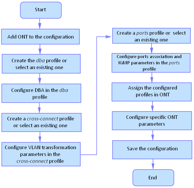
Figure 27 – ONT configuration procedure
- Step 1. Prior to proceed to ONT configuration, add an ONT into the OLT configuration. For an ONT to be added and configured, it does not need to be physically connected to the OLT. You can view the list of inactive ONTs with the help of the show interface ont <pon-port> unactivated command.
LTP-16N# show interface ont 1 unactivated
-----------------------------------
GPON-port 5 ONT unactivated list
-----------------------------------
        ##          Serial    ONT ID     PON-port     RSSI       Status
         1    ELTX0600003D       n/a            5      n/a  unactivated
- Step 2. To specify ONT settings, enter the corresponding view with the help of the interface ont command. Specify ONT serial number.
LTP-16N# configure terminal
LTP-16N(configure)# interface ont 1/1
LTP-16N(config)(if-ont-1/1)# serial ELTX0600003D
- Step 3. Apply the configuration by using the commit command.
LTP-16N(config)(if-ont-1/1)# do commit
Service configuration in the ont-mode bridge mode
Below is an example of a mixed scheme of services. ONT will be configured in the bridge mode.
Configure 3 services:
- HSI and IPTV unicast, by traffic model N-to-1, the service VLAN is 200, the tag will be taken on the ONT, untagged traffic will come from the ONT port.
- Multicast, packets will come on OLT with tag 98, from the ONT port will be untagged.
- On the N-to-1 model, with a service VLAN 100, in a separate bridge group, the ONT port will come out with a tag 10.
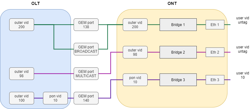
Figure 28 – Abstract representation of the test configuration
- Step 1. Create a cross-connect profile named Internet. Configure the bridged service specifying the bridge group the ONT port will be connected to (in this case, it is equal to 10 for the first service). Set the outer-vid to 200, replacing the label is not necessary and the traffic from the port comes without the tag, so leave the vlan-replace and user vid unchanged.
LTP-16N# configure terminal
LTP-16N(configure)# profile cross-connect Internet
LTP-16N(config)(profile-cross-connect-Internet)# ont-mode bridge
LTP-16N(config)(profile-cross-connect-Internet)# bridge group 10
LTP-16N(config)(profile-cross-connect-Internet)# outer vid 200
- Step 2. Analogically with the described above, create another cross-connect profile named IPTV for the second service and configure the bridge group. Additionally, allow traffic passing for multicast for this service.
LTP-16N(config)(profile-cross-connect-IPTV)# ont-mode bridge
LTP-16N(config)(profile-cross-connect-IPTV)# bridge group 11
LTP-16N(config)(profile-cross-connect-IPTV)# outer vid 98
LTP-16N(config)(profile-cross-connect-IPTV)# multicast enable
- Step 3. Create profile for the third service. Configure another group for it. Set outer-vid as 100 and user-vid as 10. Leave VLAN-replace and traffic-model without changes.
LTP-16N(configure)# profile cross-connect UNI_TAG
LTP-16N(config)(profile-cross-connect-UNI_TAG)# ont-mode bridge
LTP-16N(config)(profile-cross-connect-UNI_TAG)# bridge group 12
LTP-16N(config)(profile-cross-connect-UNI_TAG)# outer vid 100
LTP-16N(config)(profile-cross-connect-UNI_TAG)# user vid 10
- Step 4. Specify DBA parameters. To do this, create a dba profile and adjust the corresponding settings. Set a value of a guaranteed bandwidth and allocation scheme in this example:
LTP-16N(configure)# profile dba AllService
LTP-16N(config)(profile-dba-AllService)# allocation-scheme share-t-cont
LTP-16N(config)(profile-dba-AllService)# bandwidth guaranteed 1024
- Step 5. Associate bridge group with ONT port. To do this, create a ports profile and set the bridge group parameter to 10 for the eth1, eth2 port and to 11 for the eth3 port. Set the rules of multicast traffic processing for port 2 and multicast restriction rules on ONT:
LTP-16N(configure)# profile ports PP
LTP-16N(config)(profile-ports-PP)# port 1 bridge group 10
LTP-16N(config)(profile-ports-PP)# port 2 bridge group 11
LTP-16N(config)(profile-ports-PP)# port 2 multicast
LTP-16N(config)(profile-ports-PP)# port 2 igmp downstream tag-control remove-tag
LTP-16N(config)(profile-ports-PP)# port 2 igmp upstream tag-control add-tag
LTP-16N(config)(profile-ports-PP)# port 2 igmp upstream vid 98
LTP-16N(config)(profile-ports-PP)# port 2 igmp downstream vid 98
LTP-16N(config)(profile-ports-PP)# port 3 bridge group 12
LTP-16N(config)(profile-ports-PP)# igmp multicast dynamic-entry 1 group 224.0.0.1 239.255.255.255 vid 98
- Step 6. Assign the created profiles to the ONT.
LTP-16N(configure)# interface ont 1/1
LTP-16N(config)(if-ont-1/1)# service 1 profile cross-connect Internet dba AllService
LTP-16N(config)(if-ont-1/1)# service 2 profile cross-connect IPTV dba AllService
LTP-16N(config)(if-ont-1/1)# service 3 profile cross-connect UNI_TAG dba AllService
LTP-16N(config)(if-ont-1/1)# profile ports PP
- Step 7. Allow the required VLAN to pass on the uplink interface (see section Interface configuration).
LTP-16N# configure terminal
LTP-16N(configure)# interface front-port 1
LTP-16N(config)(if-front-1)# vlan allow 200,100,98
- Step 8. For VLAN 98, configure IGMP snooping. By default, IGMP snooping is enabled for all VLANs, but disabled globally. It is necessary to enable IGMP snooping globally:
LTP-16N(configure)# vlan 98
LTP-16N(config)(vlan-98)# ip igmp snooping enable
LTP-16N(config)(vlan-98)# exit
LTP-16N(configure)# ip igmp snooping enable
- Step 9. Apply configuration with the commit command.
LTP-16N# commit
Service configuration in the ont-mode router mode
Consider a typical configuration of services for ONT configured in router mode: HSI, IPTV, VoIP and ACS by model.
To do this, configure 5 services:
- HSI service. N-to-1 traffic model, service VLAN is 200, there will be a tag replacement on the OLT and it will arrive to tag 10 on the OLT.
- IPTV service. Service for multicast traffic. Multicast traffic model. The stream passes without replacing the VLAN 30 tag.
- STB service. The service is required for unicast traffic for STBs. The tag is replaced to ONT. VLAN 250.
- VoIP service. Service for telephony, similar in settings to HSI. VLAN 100.
- ACS service. This service is used to control the ONT via ACS. Service VLAN 2000.
- Step 1. Create a cross-connect profile named HSI. The ont-mode router mode is configured by default, so it is not necessary to set it. Set the service VLAN to 200 and user to 10. The tag will be replaced on OLT.
LTP-16N# configure terminal
LTP-16N(configure)# profile cross-connect HSI
LTP-16N(config)(profile-cross-connect-HSI)# outer vid 200
LTP-16N(config)(profile-cross-connect-HSI)# vlan-replace olt-side
LTP-16N(config)(profile-cross-connect-HSI)# user vid 10
- Step 2. Similarly to the described above, create another cross-connect profile named IPTV for the second service and allow multicast traffic passing.
LTP-16N(configure)# profile cross-connect IPTV
LTP-16N(config)(profile-cross-connect-IPTV)# outer vid 30
LTP-16N(config)(profile-cross-connect-IPTV)# user vid 30
LTP-16N(config)(profile-cross-connect-IPTV)# multicast enable
- Step 3. Create a cross-connect profile named STB similarly to HSI. Set the service VLAN to 250. On the terminal, the traffic will go to 40 VLAN.
LTP-16N(configure)# profile cross-connect STB
LTP-16N(config)(profile-cross-connect-STB)# outer vid 250
LTP-16N(config)(profile-cross-connect-STB)# vlan-replace olt-side
LTP-16N(config)(profile-cross-connect-STB)# user vid 40
- Step 4. Create a cross-connect profile named VOIP similar to HSI. Set the service VLAN to 100. On the terminal, the traffic will go to 20 VLAN.
LTP-16N(configure)# profile cross-connect VOIP
LTP-16N(config)(profile-cross-connect-VOIP)# outer vid 100
LTP-16N(config)(profile-cross-connect-VOIP)# vlan-replace olt-side
LTP-16N(config)(profile-cross-connect-VOIP)# user vid 20
- Step 5. Create a cross-connect profile named ACS. Set the service VLAN to 2000. Also enable iphost in this service. Leave the default index value for iphost.
LTP-16N(configure)# profile cross-connect ACS
LTP-16N(config)(profile-cross-connect-ACS)# outer vid 2000
LTP-16N(config)(profile-cross-connect-ACS)# iphost enable
- Step 6. Specify DBA parameters. To do this, create a dba profile and adjust the corresponding settings. Set a value of a guaranteed bandwidth and allocation scheme in this example:
LTP-16N(configure)# profile dba AllService
LTP-16N(config)(profile-dba-AllService)# allocation-scheme share-t-cont
LTP-16N(config)(profile-dba-AllService)# bandwidth 1024
- Step 7. Create ports profile. Add the settings to allow multicast traffic to pass through VeIP:
LTP-16N(configure)# profile ports veip
LTP-16N(config)(profile-ports-veip)# veip multicast enable
LTP-16N(config)(profile-ports-veip)# veip igmp downstream vid 30
LTP-16N(config)(profile-ports-veip)# veip igmp upstream vid 30
- Step 8. Create management profile. Add the configuration for authorization on the ACS server:
LTP-16N(configure)# profile management ACS
LTP-16N(config)(profile-management-ACS)# username test
LTP-16N(config)(profile-management-ACS)# password test_pass
LTP-16N(config)(profile-management-ACS)# url http://192.168.100.100
- Step 9. Assign the created profiles to the ONT.
LTP-16N(configure)# interface ont 1/1
LTP-16N(config)(if-ont-1/1)# service 1 profile cross-connect HSI dba AllService
LTP-16N(config)(if-ont-1/1)# service 2 profile cross-connect IPTV dba AllService
LTP-16N(config)(if-ont-1/1)# service 3 profile cross-connect STB dba AllService
LTP-16N(config)(if-ont-1/1)# service 4 profile cross-connect VOIP dba AllService
LTP-16N(config)(if-ont-1/1)# service 5 profile cross-connect ACS dba AllService
LTP-16N(config)(if-ont-1/1)# profile ports veip
LTP-16N(config)(if-ont-1/1)# profile management ACS
- Step 10. Allow the required VLAN to pass on the uplink interface (see section Interface configuration).
LTP-16N# configure terminal
LTP-16N(configure)# interface front-port 1
LTP-16N(config)(if-front-1)# vlan allow 100,200,250,2000
- Step 11. For VLAN 30, configure IGMP snooping. Also, enable IGMP snooping globally:
LTP-16N(configure)# vlan 30
LTP-16N(config)(vlan-30)# ip igmp snooping enable
LTP-16N(config)(vlan-30)# exit
LTP-16N(configure)# ip igmp snooping enable
- Step 12. Apply configuration with the commit command.
LTP-16N# commit
Configuration templates
It is not always convenient for carriers, especially large ones, to assemble ONT configuration from profiles for each subscriber. This is time-consuming and, in a certain sense, risky, since it increases the likelihood of carrier errors. As a rule, companies use one or more service plans, under which ONT profiles are defined.
This section describes ONT templates. The mechanics of configuration templates is very simple. The network administrator prepares in advance the required number of templates according to the number of service plans. The configuration template specifies a list of profiles, as well as a set of ONT parameters with maximum detail. The subscriber department engineer or the OSS/BSS system assigns the template to the ONT and redefines some additional configuration parameters, if necessary. As a rule, the assignment of a configuration through templates occurs in one click or in one command.
- Step 1. Create ONT configuration template.
LTP-16N# configure terminal
LTP-16N(configure)# template one_service
LTP-16N(config)(template-one_service)#
- Step 2. Assign previously created ONT profiles to the required services. As an example, cross-connect profile with PPPoE name and dba profile with dba1 name.
LTP-16N(config)(template-one_service)#
LTP-16N(config)(template-one_service)# service 1 profile cross-connect PPPoE dba dba1
Step 3. Enable redefining parameters assigned from templates.
By default, all parameters in template are undefine (parameters will use settings not from the template, but only those that were assigned to the interface ont). To use configuration specified in template, configure define for each parameter.
LTP-16N(config)(template-one_service)# define service 1
- Step 4. Apply configuration with the commit command.
LTP-16N(config)(template-one_service)# do commit
Assigning ONT configuration template
- Step 1. Switch to ONT configuration. If necessary, ONT ID range can be used for group operations.
LTP-16N# configure terminal
LTP-16N(configure)# interface ont 1/1
LTP-16N(config)(if-ont-1/1)#
- Step 2. Assign configuration template to ONT.
LTP-16N(config)(if-ont-1/1)# template one_service
- Step 3. If necessary, set individual options for ONT that are not specified in template. For example, RF-port activation and error correction in upstream direction.
LTP-16N(config)(if-ont-1/1)# rf-port-state enable
LTP-16N(config)(if-ont-1/1)# fec
For LTX-8(16), FEC is enabled by default.
- Step 4. Apply configuration with the commit command.
LTP-16N(config)(if-ont-1/1)# do commit
Disabling ONT
Starting with 1.4.0 firmware version, the ability to remotely disable the interface ONT has been added.
LTP-16N# configure terminal
LTP-16N(config)# interface ont 1/1
LTP-16N(config)(if-ont-1/1)# shutdown
LTP-16N(config)(if-ont-1/1)# do commit
Tunneling configuration
Ordinary profiles with tag-mode single-tag and double-tag are aimed at converting traffic going to the gem with the user vid or untagged tag into traffic with the outer vid or outer:inner vid tags, respectively.
Configuration of cross-connect profile in traffic tunneling mode allows expanding the range of possible schemes for using GPON on operator’s network.
Profiles with tag-mode tunnel allow adding a tag to received packet with any user-vid tags.
Below is an example of such scheme and its configuration.
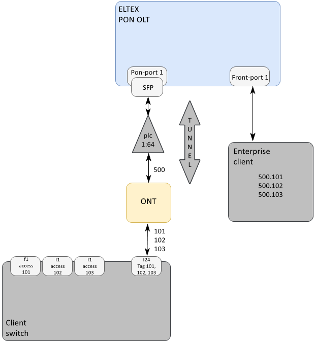
Figure 29 — Communication organization diagram
Client's switch is connected to splitter via ONT. The client uses a random set of VLANs (101, 102, 103), which are configured only on the client equipment. VLAN 500 is selected on the operator's network to create a tunnel for this client.
Traffic with client VLAN tags comes from ONT LAN port to switch port (f24). Traffic with two tags (500.101, 500.102, etc.) arrives from the client equipment to the Front OLT port.
Below is an example of OLT configuration for organizing the scheme described above.
Step 1. Create profile cross-connect in traffic tunneling mode.
LTP-16N# configure terminal
LTP-16N(configure)# profile cross-connect cc-tunnel1
LTP-16N(config)(profile-cross-connect-cc-tunnel1)# outer vid 500
LTP-16N(config)(profile-cross-connect-cc-tunnel1)# ont-mode bridge
LTP-16N(config)(profile-cross-connect-cc-tunnel1)# bridge group 2
LTP-16N(config)(profile-cross-connect-cc-tunnel1)# multicast enable
LTP-16N(config)(profile-cross-connect-cc-tunnel1)# tag-mode tunnel
LTP-16N(config)(profile-cross-connect-cc-tunnel1)# traffic-model 1-to-1
LTP-16N(config)(profile-cross-connect-cc-tunnel1)# exit
Step 2. Add profile port configuration.
LTP-16N(configure)# profile ports t1
LTP-16N(config)(profile-ports-t1)# port 1 bridge group 2
LTP-16N(config)(profile-ports-t1)# exit
Step 3. Assign the corresponding profiles to the ONT interface.
LTP-16N(configure)# interface ont 1/1
LTP-16N(config)(if-ont-1/1)# service 1 profile cross-connect cc-tunnel1 dba dba1
LTP-16N(config)(if-ont-1/1)# profile ports t1
LTP-16N(config)(if-ont-1/1)# exit
Step 4. Add vlan to front-port.
LTP-16N# configure terminal
LTP-16N(configure)# interface front-port 1
LTP-16N(config)(if-front-1)# vlan allow 500
LTP-16N(config)(if-front-1)# exit
Step 5. For passing multicast traffic through the tunnel, disable ip igmp snooping in VLAN used for tunneling:
LTP-16N(configure)# vlan 500
LTP-16N(config)(vlan-500)# no ip igmp snooping enable
LTP-16N(config)(vlan-500)# exit
Step 6. It is recommended to disable ip dhcp snooping for VLAN used for tunneling:
LTP-16N(configure)# ip dhcp
LTP-16N(config)(dhcp)# no snooping enable vlan 500
LTP-16N(config)(dhcp)# exit
Step 7. Apply changes with the commit command.
LTP-16N(config)# do commit
A tunnel VLAN tag of 500 will be added to all traffic from ONT to upstream.
Tunneling mode is supported only with traffic-model 1-to-1.
Traffic going through the tunnel with random user-vid tag should not contain additional 802.1q tags (Q-in-Q). Such traffic will be rejected by any service that this user-vid falls under.
VLAN involved in tunnel services cannot be involved in services of other type within one gpon channel.
In tag-mode tunnel mode, inner vid and user vid configuration does not affect traffic passing in tunnel.
Tunneling should be used only with tagged traffic.
The number of VLANs used within a tunnel may be limited in some ONT models.
Upstream traffic tagging configuration
CoS tagging of traffic allows overwriting the 3-bit priority (PCP) field in the L2 headers of upstream packets. Tagging is configured in cross-connect profile.
Step 1. Go to view of cross-connect profile, settings of which should be changed.
LTP-16N# configure terminal
LTP-16N(configure)# profile cross-connect test
LTP-16N(config)(profile-cross-connect-test)#
Step 2. Set outer upstream cos value for this profile.
LTP-16N(config)(profile-cross-connect-test)# outer upstream cos 7
LTP-16N(config)(profile-cross-connect-test)# do commit
Step 3. If necessary, set inner upstream cos value for this profile.
LTP-16N(config)(profile-cross-connect-test)# inner upstream cos 7
LTP-16N(config)(profile-cross-connect-test)# do commit
In single-tagged or tunnel mode only outer-vid tagging is possible.
In double-tag mode tagging is limited. There are 3 options available:
1. Only outer-tag tagging;
2. Only inner-tag tagging;
3. Both tags are marked, but with the same value.
Overriding the parameters specified in the cross-connect profile. Custom parameters
In some cases it is necessary to specify unique VLAN ID for ONT. For this task, custom parameters can be used instead of creating separate profile.
Custom outer vid
LTP-16N# configure terminal
LTP-16N(config)# interface ont 1/1
LTP-16N(config)(if-ont-1/1)# service 1 custom outer vid 1000
LTP-16N(config)(if-ont-1/1)# do commit
In this case, outer vid from cross-connect profile will be replaced to VLAN specified in custom outer vid of the service.
Custom inner vid
LTP-16N(config)(if-ont-1/1)# service 1 custom inner vid 2000
LTP-16N(config)(if-ont-1/1)# do commit
In this case, inner vid from cross-connect profile will be replaced to VLAN specified in custom inner vid of the service.
Custom outer upstream cos
LTP-16N(config)(if-ont-1/1)# service 1 custom outer upstream cos 7
LTP-16N(config)(if-ont-1/1)# do commit
In this case, outer upstream cos from cross-connect profile will be replaced to VLAN specified in custom outer upstream cos of the service.
Custom inner upstream cos
LTP-16N(config)(if-ont-1/1)# service 1 custom inner upstream cos 7
LTP-16N(config)(if-ont-1/1)# do commit
In this case, inner upstream cos from cross-connect profile will be replaced to VLAN specified in custom inner upstream cos of the service.
In double-tag mode tagging is limited. There are 3 options available:
- Only outer-tag tagging;
- Only inner-tag tagging;
- Outer-tag and inner-tag tagging at the same time, but with the same value.
Custom mac-table-limit
LTP-16N(config)(if-ont-1/1)# service 1 custom mac-table-limit 5
LTP-16N(config)(if-ont-1/1)# do commit
In this case, mac-table-limit from cross-connect profile will be replaced to custom mac-table-limit for service 1.
DBA configuration
This section describes parameters configuration for ONT.
In GPON technology all ONT on the same GPON channel use the same transmission media (fiber). A mechanism is needed that would ensure data transmission from all ONTs without collisions. Such a mechanism called dynamic bandwidth allocation (DBA) ensures allocation of time intervals on OLT to transmit traffic to ONT.
DBA works with Alloc-ID (allocation) logical unit which corresponds to T-CONT (traffic container) on ONT side. Traffic transmission parameters (frequency and window size for transmission) are configured for each Alloc-ID (T-CONT) individually. Such parameters are called service level agreement (SLA).
G.984.3 provides several options for combinations of SLA parameters, called T-CONT type. There are the following T-CONT types:
- T-CONT type 1 characterized only by a fixed band (cbr-rt bandwidth/cbr-nrt bandwidth). Suitable for traffic that travels at a constant speed (or has very small fluctuations) and is sensitive to delays and jitter.
- T-CONT type 2 characterized only by a guaranteed band (guaranteed bandwidth). Suitable for periodically occurring traffic with a clear upper limit, without strict restrictions on delays and jitter.
- T-CONT type 3 characterized by a guaranteed band (guaranteed bandwidth) with the ability to allocate additional band (maximum bandwidth). Suitable for variable traffic with periodic bursts that require some level of throughput guarantee.
- T-CONT type 4 characterized by the ability to allocate a free band (maximum bandwidth) without fixed or guaranteed part. Suitable for variable traffic with periodic bursts, which does not require any bandwidth guarantees.
- T-CONT type 5 characterized by fixed (cbr-rt bandwidth/cbr-nrt bandwidth) and guaranteed part (guaranteed bandwidth) with the ability to allocate additional band (maximum bandwidth). This T-CONT type is a generalization of all the previous ones and is suitable for most types of traffic.
The terminal allows configuring up to 640 general allocation per channel for GPON. When connecting one ONT, at least one allocation will be allocated as a default allocation. Thus, when 128 subscribers are connected to the channel, 128 service allocations will be allocated. The remaining 512 allocations can be used for services configuration. If total number of services for all ONTs exceeds 512 allocations, combine several services into one allocation.
The terminal allows configuring up to 1024 general allocation per channel for XGS-GPON. When connecting one ONT, at least one allocation will be allocated as a default allocation. Thus, when 256 subscribers are connected to the channel, 256 service allocations will be allocated. The remaining 768 allocations can be used for services configuration. If total number of services for all ONTs exceeds 512 allocations, combine several services into one allocation. For more information check Services in one T-CONT.
DBA parameters are configured in dba profile. Using these settings, it is possible to set any of the T-CONT types described in G.984.3. First select t-cont-type defining basic DBA algorithm. Then configure status-reporting, defining report type on ONT queue states. Fixed, guaranteed, and maximum bands are specified by cbr, guaranteed, maximum parameters respectively. Table 28 lists correspondence of dba profile settings to T-CONT types.
Table 28 — Correspondence of dba profile settings to T-CONT types
| Traffic band components | T-CONT type | ||||
| type 1 | type 2 | type 3 | type 4 | type 5 | |
| cbr-rt bandwidth (real time) | cbr-rt | - | - | - | cbr-rt |
| cbr-nrt bandwidth (non-real time) | cbr-nrt | - | - | - | cbr-nrt |
guaranteed bandwidth | guaranteed = cbr-rt + cbr-nrt | guaranteed | guaranteed | - | guaranteed >= cbr-rt + cbr-nrt |
| maximum bandwidth | maximum = guaranteed | maximum = guaranteed | maximum > guaranteed | maximum | maximum > guaranteed |
| additional-eligibility | none | none | non-assured | best-effort | non-assured or best-effort |
| dba status reporting mode | none | NSR or SR | NSR or SR | NSR or SR | NSR or SR |
Only non-null components are listed. | |||||
This table shows the relationships and possible profile parameter values for each T-CONT. For example, for T-CONT type 2 there are no fixed bandwidth components, and the maximum and guaranteed components must be equal when configured.
Ruled of dba profiles assignment:
- when assigning dba profile to service on ONT, Alloc-ID is created for this ONT on OLT side. The corresponding T-CONT is configured on ONT side;
- if the same profile is assigned to different ONTs, then for each ONT its own Alloc-ID will be created, and the parameters of these allocations will be the same;
- if the same dba profiles are assigned to different services of the same ONT and the allocation-scheme share-t-cont is specified, then these services will operate in the same allocation, and the allocation parameters will be common for the services;
- if the same dba profiles are assigned to different services of the same ONT and the allocate-new-t-cont is specified,then these services will operate in different allocations, and number of Alloc-ID created for ONT is equal to number of dba profiles assigned to it.
All configuration examples in this section are concerning gpon unless explicitly stated otherwise.
DBA profiles assignment
Configuring pon-type
For LTX-8(16), PON-ports can operate using GPON or XGS-PON technology. Therefore, in the DBA profile it is also necessary to specify the operating mode corresponding to the PON-port operating mode. By default, XGS-PON mode is used. If it is necessary to change the profile operating mode, perform the following steps:
Step 1. Change operation mode to GPON:
LTX-16# configure terminal
LTX-16(configure)# profile dba dba1
LTX-16(config)(profile-dba-dba1)# pon-type gpon
    Selected command 'pon-type gpon' in candidate configuration it is different from the one in running configuration.
    In this case, some previously set bandwidth values may become invalid and will not pass validation during commit.
Step 2. Apply changes with the commit command:
LTX-16(config)(profile-dba-dba1)# do commit
Services in different T-CONT
For ONT on OLT two Alloc-ID will be allocated. Each service will operate in its own allocation. Allocations will correspond to two T-CONTs from the ONT side.
Step 1. It is necessary for one ONT to have two services in different T-CONTs. To do this, define two dba profiles with the profile dba command.
LTP-16N(config)# profile dba ServiceInternet
LTP-16N(config)(profile-dba-ServiceInternet)# exit
LTP-16N(config)# profile dba ServiceVoIP
LTP-16N(config)(profile-dba-ServiceVoIP)# exit
Step 2. Specify an individual allocation distribution scheme with the allocation-scheme command.
LTP-16N(config)#profile dba ServiceInternet
LTP-16N(config)(profile-dba-ServiceInternet)# allocation-scheme allocate-new-t-cont
LTP-16N(config)(profile-dba-ServiceInternet)# exit
LTP-16N(config)# profile dba ServiceVoIP
LTP-16N(config)(profile-dba-ServiceVoIP)# allocation-scheme allocate-new-t-cont
LTP-16N(config)(profile-dba-ServiceVoIP)# exit
Step 3. Assign profiles to services with the service <id> profile dba command.
LTP-16N(config)(if-ont-1/1)# service 1 profile cross-connect HSI dba ServiceInternet
LTP-16N(config)(if-ont-1/1)# service 2 profile cross-connect VOIP dba ServiceVoIP
Step 4. Apply configuration with the commit command.
LTP-16N(config)(if-ont-1/1)# do commit
The configuration will look as follows:LTP-16N(config)(if-ont-1/1)# do show interface ont 1/1 configuration ... Service[1]: Profile cross-connect: HSI ONT Profile Cross-Connect 3 Profile dba: ServiceInternet ONT Profile DBA 3 Service[2]: Profile cross-connect: VOIP ONT Profile Cross-Connect 5 Profile dba: ServiceVoIP ONT Profile DBA 4 ...
Services in one T-CONT
For ONT on OLT one Alloc-ID will be allocated. T-CONT will be configured on ONT. The traffic of several services will go through it.
Step 1. It is necessary for ONT to have three services in one T-CONT. To do this, define the dba profile with the profile dba command.
LTP-16N(configure)# profile dba AllServices
Step 2. It is necessary for ONT to have all services in one T-CONT. To do this, define an allocation-scheme allocation scheme.
LTP-16N(config)(profile-dba-AllServices)# allocation-scheme share-t-cont
Step 3. Assign this profile to three services with the service <id> profile dba command.
LTP-16N(config)(if-ont-1/1)# service 1 profile cross-connect HSI dba AllServices
LTP-16N(config)(if-ont-1/1)# service 2 profile cross-connect VOIP dba AllServices
LTP-16N(config)(if-ont-1/1)# service 3 profile cross-connect IPTV dba AllServices
Step 4. Apply configuration with the commit command.
LTP-16N(config)(if-ont-1/1)# do commit
The configuration will look as follows:
LTP-16N(config)(if-ont-1/1)# do show interface ont 1/1 configuration
...
    Service[1]:
        Profile cross-connect:          HSI            ONT Profile Cross-Connect 3
        Profile dba:                    AllServices    ONT Profile DBA 5
    Service[2]:
        Profile cross-connect:          VOIP           ONT Profile Cross-Connect 5
        Profile dba:                    AllServices    ONT Profile DBA 5
    Service[3]:
        Profile cross-connect:          IPTV           ONT Profile Cross-Connect 4
        Profile dba:                    AllServices    ONT Profile DBA 5
...
One profile for several ONTs
This scenario is a typical scenario in most cases. DBA parameters for the same services should be the same on different ONTs.
Step 1. Define dba profile with the profile dba command.
LTP-16N(configure)# profile dba ServiceInternet
Step 2. Assign profile to a corresponding service for each ONT with the service <id> profile dba command.
LTP-16N(configure)# interface ont 1/1-2
LTP-16N(config)(if-ont-1/1-2)# service 1 profile dba ServiceInternet
Step 3. Apply configuration with the commit command.
LTP-16N(config)(if-ont-1/1-2)# do commit
The ONT configurations will look as follows:
LTP-16N(config)(if-ont-1/1-2)# do show interface ont 1/1-2 configuration
-----------------------------------
[ONT 1/1] configuration
-----------------------------------
...
    Service[1]:
        Profile cross-connect:          HSI                ONT Profile Cross-Connect 3
        Profile dba:                    ServiceInternet    ONT Profile DBA 3
...
-----------------------------------
[ONT 1/1] configuration
-----------------------------------
...
    Service[1]:
        Profile cross-connect:          HSI                ONT Profile Cross-Connect 3
        Profile dba:                    ServiceInternet    ONT Profile DBA 3
...
Example of profiles assignment
It is necessary to assign three services to two ONTs: Internet, VoIP, SecurityAlarm. If necessary, VoIP operation requires a separate allocation (guarantee of bandwidth is needed). Internet and SecurityAlarm can operate in the same allocation.
In such configuration two Alloc-ID are allocated for each ONT on OLT. Internet and SecurityAlarm services operate in one allocation, and VoIP operates in another one. Two T-CONTs corresponding to Alloc-ID of this ONT are configured on each ONT.
Step 1. Define two dba profiles with the profile dba command.
LTP-16N(configure)# profile dba ServiceVoIP
LTP-16N(config)(profile-dba-ServiceVoIP)# exit
LTP-16N(configure)# profile dba OtherServices
LTP-16N(config)(profile-dba-OtherServices)# exit
Step 2. Specify an individual allocation distribution scheme with the allocation-scheme command.
LTP-16N(configure)# profile dba ServiceVoIP
LTP-16N(config)(profile-dba-ServiceVoIP)# allocation-scheme allocate-new-t-cont
LTP-16N(config)(profile-dba-ServiceVoIP)# exit
LTP-16N(configure)# profile dba OtherServices
LTP-16N(config)(profile-dba-OtherServices)# exit
Step 3. Assign profiles to corresponding services for each ONT with the service <id> profile dba command.
LTP-16N(configure)# interface ont 1/1-2
LTP-16N(config)(if-ont-1/1-2)# service 1 profile dba OtherServices
LTP-16N(config)(if-ont-1/1-2)# service 2 profile dba ServiceVoIP
LTP-16N(config)(if-ont-1/1-2)# service 3 profile dba OtherServices
Step 4. Apply configuration with the commit command.
LTP-16N(config)(if-ont-1/1-2)# do commit
DBA parameters configuration
T-CONT type 1 configuration
T-CONT type 1 allows configuring a fixed bandwidth. Below is an example of configuration of 100 Mbps fixed bandwidth.
Step 1. Specify T-CONT type with the t-cont-type command.
LTP-16N(configure)# profile dba dba1
LTP-16N(config)(profile-dba-dba1)# t-cont-type 1
Step 2. Specify type of ONT queue status reports with the mode command.
LTP-16N(config)(profile-dba-dba1)# mode none
Step 3. Specify fixed bandwidth parameters with the cbr-nrt bandwidth or cbr-rt bandwidth command.
Bandwidth value is specified in Kbps (1000 bps), and is rounded to 64 Kbps downstream in GPON mode and to 1024 Kbps downstream in XGS-PON mode.
- cbr-rt bandwidth – fixed bandwidth that requires precise management of bandwidth distribution. Suitable for traffic that is sensitive to delays and jitter.
- cbr-nrt bandwidth – fixed bandwidth that does not require precise management of bandwidth distribution. Suitable for less sensitive traffic types.
It is permissible to use these bands together or separately. In this example cbr-nrt bandwidth is used.GPON mode:
LTP-16N(config)(profile-dba-dba1)# cbr-nrt bandwidth 100000
The value must be a multiple of 64. 100000 will be automatically adjusted to 99968
XGS-PON mode:LTX-8(config)(profile-dba-q)# cbr-nrt bandwidth 100000 The value must be a multiple of 1024 because 'pon-type xgs-pon' is selected into the DBA profile in running configuration and not changed in candidate. 100000 will be automatically adjusted to 99328Step 4. Specify guaranteed and maximum bandwidth parameters with the guaranteed bandwidth and maximum bandwidth commands. For t-cont-type 1 they will be equal to the sum of cbr-rt and cbr-nrt.
GPON mode:
LTP-16N(config)(profile-dba-dba1)# guaranteed bandwidth 100000 The value must be a multiple of 64. 100000 will be automatically adjusted to 99968 LTP-16N(config)(profile-dba-dba1)# maximum bandwidth 100000 The value must be a multiple of 64. 100000 will be automatically adjusted to 99968XGS-PON mode:
LTX-8(config)(profile-dba-q)# guaranteed bandwidth 100000 The value must be a multiple of 1024 because 'pon-type xgs-pon' is selected into the DBA profile in running configuration and not changed in candidate. 100000 will be automatically adjusted to 99328 LTX-8(config)(profile-dba-q)# maximum bandwidth 100000 The value must be a multiple of 1024 because 'pon-type xgs-pon' is selected into the DBA profile in running configuration and not changed in candidate. 100000 will be automatically adjusted to 99328Step 5. Specify parameters for adding an additional dynamic band with the additional-eligibility command. Only none value is acceptable for t-cont-type 1.
LTP-16N(config)(profile-dba-dba1)# additional-eligibility none
Step 6. Apply configuration with the commit command.
LTP-16N(config)(profile-dba-dba1)# do commit
If inappropriate values are specified for one or more parameters for a given t-cont type, an error will occur, accompanied by a detailed description of the acceptable parameter values.
T-CONT type 2 configuration
T-CONT type 2 allows configuring a guaranteed bandwidth. Below is an example of configuration of 100 Mbps guaranteed bandwidth.
Step 1. Specify T-CONT type with the t-cont-type command.
LTP-16N(configure)# profile dba dba1 LTP-16N(config)(profile-dba-dba1)# t-cont-type 2
Step 2. Specify type of ONT queue status reports with the mode command.
LTP-16N(config)(profile-dba-dba1)# mode non-status-reporting
Step 3. Specify guaranteed bandwidth parameters with the guaranteed bandwidth command.
Bandwidth value is specified in Kbps (1000 bps), and is rounded to 64 Kbps downstream in GPON mode and to 1024 Kbps downstream in XGS-PON mode.
GPON mode:
LTP-16N(config)(profile-dba-dba1)# guaranteed bandwidth 100000 The value must be a multiple of 64. 100000 will be automatically adjusted to 99968XGS-PON mode:
LTX-8(config)(profile-dba-q)# guaranteed bandwidth 100000 The value must be a multiple of 1024 because 'pon-type xgs-pon' is selected into the DBA profile in running configuration and not changed in candidate. 100000 will be automatically adjusted to 99328Step 4. Specify maximum bandwidth parameters with the maximum bandwidth command. For t-cont-type 2 they will be equal to guaranteed bandwidth.
GPON mode:LTP-16N(config)(profile-dba-dba1)# maximum bandwidth 100000 The value must be a multiple of 64. 100000 will be automatically adjusted to 99968XGS-PON mode:
LTX-8(config)(profile-dba-q)# maximum bandwidth 100000 The value must be a multiple of 1024 because 'pon-type xgs-pon' is selected into the DBA profile in running configuration and not changed in candidate. 100000 will be automatically adjusted to 99328Step 5. Specify parameters for adding an additional dynamic band with the additional-eligibility command. Only none value is acceptable for t-cont-type 2.
LTP-16N(config)(profile-dba-dba1)# additional-eligibility none
Step 6. Apply configuration with the commit command.
LTP-16N(config)(profile-dba-dba1)# do commit
If inappropriate values are specified for one or more parameters for a given t-cont type, an error will occur, accompanied by a detailed description of the acceptable parameter values.
T-CONT type 3 configuration
T-CONT type 3 allows configuring a guaranteed bandwidth with possibility of allocating additional bandwidth. Below is an example of configuration of 100 Mbps guaranteed bandwidth possibility of allocating additional bandwidth of up to 200 Mbps.
Step 1. Specify T-CONT type with the t-cont-type command.
LTP-16N(configure)# profile dba dba1 LTP-16N(config)(profile-dba-dba1)# t-cont-type 3
Step 2. Specify type of ONT queue status reports with the mode command.
LTP-16N(config)(profile-dba-dba1)# mode non-status-reporting
Step 3. Specify guaranteed bandwidth parameters with the guaranteed bandwidth command.
Bandwidth value is specified in Kbps (1000 bps), and is rounded to 64 Kbps downstream in GPON mode and to 1024 Kbps downstream in XGS-PON mode.
GPON mode:
LTP-16N(config)(profile-dba-dba1)# guaranteed bandwidth 100000 The value must be a multiple of 64. 100000 will be automatically adjusted to 99968XGS-PON mode:
LTX-8(config)(profile-dba-q)# guaranteed bandwidth 100000 The value must be a multiple of 1024 because 'pon-type xgs-pon' is selected into the DBA profile in running configuration and not changed in candidate. 100000 will be automatically adjusted to 99328Step 4. Specify maximum bandwidth parameters with the maximum bandwidth command.
GPON mode:
LTP-16N(config)(profile-dba-dba1)# maximum bandwidth 200000
XGS-PON mode:
LTX-8(config)(profile-dba-q)# maximum bandwidth 200000 The value must be a multiple of 1024 because 'pon-type xgs-pon' is selected into the DBA profile in running configuration and not changed in candidate. 200000 will be automatically adjusted to 199680Step 5. Specify parameters of allocating additional bandwidth with the additional-eligibility command.
LTP-16N(config)(profile-dba-dba1)# additional-eligibility non-assured
Step 6. Apply configuration with the commit command.
LTP-16N(config)(profile-dba-dba1)# do commit
If inappropriate values are specified for one or more parameters for a given t-cont type, an error will occur, accompanied by a detailed description of the acceptable parameter values.
T-CONT type 4 configuration
T-CONT type 4 allows configuring maximum bandwidth without possibility of allocating guaranteed bandwidth. Below is an example of configuration of 200 Mbps guaranteed bandwidth.
Step 1. Specify T-CONT type with the t-cont-type command.
LTP-16N(configure)# profile dba dba1 LTP-16N(config)(profile-dba-dba1)# t-cont-type 4
Step 2. Specify type of ONT queue status reports with the mode command.
LTP-16N(config)(profile-dba-dba1)# mode non-status-reporting
Step 3. Specify guaranteed bandwidth parameters with the guaranteed bandwidth command.
Bandwidth value is specified in Kbps (1000 bps), and is rounded to 64 Kbps downstream in GPON mode and to 1024 Kbps downstream in XGS-PON mode.
LTP-16N(config)(profile-dba-dba1)# guaranteed bandwidth 0
Step 4. Specify maximum bandwidth parameters with the maximum bandwidth command.
GPON mode:
LTP-16N(config)(profile-dba-dba1)# maximum bandwidth 200000
XGS-PON mode:
LTX-8(config)(profile-dba-q)# maximum bandwidth 200000 The value must be a multiple of 1024 because 'pon-type xgs-pon' is selected into the DBA profile in running configuration and not changed in candidate. 200000 will be automatically adjusted to 199680Step 5. Apply configuration with the commit command.
LTP-16N(config)(profile-dba-dba1)# do commit
If inappropriate values are specified for one or more parameters for a given t-cont type, an error will occur, accompanied by a detailed description of the acceptable parameter values.
T-CONT type 5 configuration
T-CONT type 5 allows agile DBA profile configuration. Below is an example of configuration of 100 Mbps fixed bandwidth, 200 Mbps guaranteed bandwidth with possibility of allocating additional bandwidth of up to 1244 Mbps for GPON mode and up to 9820 Mbps for XGS-PON mode.
Step 1. Specify T-CONT type with the t-cont-type command.
LTP-16N(configure)# profile dba dba1 LTP-16N(config)(profile-dba-dba1)# t-cont-type 5
Step 2. Specify type of ONT queue status reports with the mode command.
LTP-16N(config)(profile-dba-dba1)# mode non-status-reporting
Step 3. Specify fixed bandwidth parameters with the cbr-nrt bandwidth or cbr-rt bandwidth command.
Bandwidth value is specified in Kbps (1000 bps), and is rounded to 64 Kbps downstream in GPON mode and to 1024 Kbps downstream in XGS-PON mode.
GPON mode:
LTP-16N(config)(profile-dba-dba1)# cbr-nrt bandwidth 100000 The value must be a multiple of 64. 100000 will be automatically adjusted to 99968
XGS-PON mode:
LTX-8(config)(profile-dba-q)# cbr-nrt bandwidth  100000
    The value must be a multiple of 1024 because 'pon-type xgs-pon' is selected into the DBA profile in running configuration and not changed in candidate.
    100000 will be automatically adjusted to 99328
Step 4. Specify guaranteed and maximum bandwidth parameters with the guaranteed bandwidth and maximum bandwidth commands.
GPON mode:LTP-16N(config)(profile-dba-dba1)# guaranteed bandwidth 200000 LTP-16N(config)(profile-dba-dba1)# maximum bandwidth 1244000 The value must be a multiple of 64. 1244000 will be automatically adjusted to 1243968XGS-PON mode:
LTX-8(config)(profile-dba-q)# guaranteed bandwidth 200000
    The value must be a multiple of 1024 because 'pon-type xgs-pon' is selected into the DBA profile in running configuration and not changed in candidate.
    200000 will be automatically adjusted to 199680
LTX-8(config)(profile-dba-q)# maximum bandwidth 9820160
Step 5. Specify parameters of allocating additional dynamical bandwidth with the additional-eligibility command.
LTP-16N(config)(profile-dba-dba1)# additional-eligibility non-assured
Step 6. Apply configuration with the commit command.
LTP-16N(config)(profile-dba-dba1)# do commit
If inappropriate values are specified for one or more parameters for a given t-cont type, an error will occur, accompanied by a detailed description of the acceptable parameter values.
Downstream policer configuration
Downstream policer is a functionality allowing limiting downstream data transmission. All packets above limit will be dropped. Policer can be configured both for all traffic on ONT and for a separate service.
Below is an example of configuration of 100 Mbps bandwidth limit for all services.
Step 1. Enable use of policer. In this case policer is enabled for all services on ONT.
LTP-16N(configure)# profile shaping 1
LTP-16N(config)(profile-shaping-1)# downstream policer enable
Step 2. Set values for commited-rate and peak-rate. Peak-rate is a peak rate, packets above this rate will be dropped. Commited-rate is a guaranteed rate, at which packets will be transmitted without loss. If peak-rate is more than commited-rate, then the band between them will be available for traffic transmission, but losses are possible.
LTP-16N(config)(profile-shaping-1)# downstream policer commited-rate 100000
    The rate must be a multiple of 64. 100000 will be automatically adjusted to 99968
LTP-16N(config)(profile-shaping-1)# downstream policer peak-rate 100000
    The rate must be a multiple of 64. 100000 will be automatically adjusted to 99968
Step 3. Apply configuration with the commit command.
LTP-16N(config)(profile-shaping-1)# do commit
    	Configuration committed successfully
It is also possible to configure policer separately for required services.
LTP-16N(config)(profile-shaping-1)# downstream 1 policer enable
LTP-16N(config)(profile-shaping-1)# downstream 1 policer commited-rate 100000
    The rate must be a multiple of 64. 100000 will be automatically adjusted to 99968
LTP-16N(config)(profile-shaping-1)# downstream 1 policer peak-rate 100000
    The rate must be a multiple of 64. 100000 will be automatically adjusted to 99968
LTP-16N(config)(profile-shaping-1)# do commit
    	Configuration committed successfully
In this example, the bandwidth limit for the first service was configured at 100 Mbit/s.
Storm-control configuration on ONT in upstream direction
For protection against storms occurring in the PON segment of the OLT, advanced functionality of the shaping profile can be used.
The limit is set for broadcast and multicast traffic in the number of packets per second. If necessary, logging of an event can be ensured when a threshold is exceeded, and the ONT can be blocked.
Step 1. Enter the view of the required shaping profile.
LTP-16N# configure terminal LTP-16N(configure)# profile shaping 1 LTP-16N(config)(profile-shaping-1)#
Step 2. Enable strom-control for broadcast- and multicast traffic.
LTP-16N(config)(profile-shaping-1)# upstream multicast storm-control enable LTP-16N(config)(profile-shaping-1)# upstream broadcast storm-control enable
Step 3. Set rate-limit value, at which storm-control will be triggered, in packets per second.
LTP-16N(config)(profile-shaping-1)# upstream multicast storm-control rate-limit 2000 LTP-16N(config)(profile-shaping-1)# upstream broadcast storm-control rate-limit 2000
Step 4. Select an action when a storm is detected.
LTP-16N(config)(profile-shaping-1)# upstream multicast storm-control logging shutdown LTP-16N(config)(profile-shaping-1)# upstream broadcast storm-control logging shutdown
Step 5. If necessary, change ONT blocking time. It is configured in global configuration. Default value is 120 seconds.
LTP-16N(configure)# pon olt ont-block-time 300
Step 6. Apply configuration with the commit command.
LTP-16N(configure)# do commit
Mapping VLANs configuration using one GEM-port
Assignment of cross-connect profile creates a service GEM-порт (logical data channel in GPON technology, used for data transmission between OLT and ONT), to which the vids specified in this cross-connect are mapped.
Only one cross-connect profile can be assigned to one service. Thus, it is possible to set only one VLAN conversion on one service in standard mode. Mapping allows bypassing this limitation and assigning additional VLANs to one GEM port. The total number of mapping rules available for configuration on one ONT is 255, however, different ONT models support different numbers of rules.
Step 1. Create profile cross-connect with required parameters, and profile ports. First profile will use tag-mode double-tagged, while in the second, it is necessary to retain the tag-mode single-tagged. Values of vid must be different from the ones to be configured in mapping rules.
LTP-16N(configure)# profile cross-connect crossconnect1 LTP-16N(config)(profile-cross-connect-crossconnect1)# outer vid 2000 LTP-16N(config)(profile-cross-connect-crossconnect1)# inner vid 500 LTP-16N(config)(profile-cross-connect-crossconnect1)# user vid 10 LTP-16N(config)(profile-cross-connect-crossconnect1)# tag-mode double-tagged LTP-16N(config)(profile-cross-connect-crossconnect1)# vlan-replace olt-side LTP-16N(config)(profile-cross-connect-crossconnect1)# traffic-model 1-to-1 LTP-16N(config)(profile-cross-connect-crossconnect1)# ont-mode bridge LTP-16N(config)(profile-cross-connect-crossconnect1)# bridge group 1 LTP-16N(config)(profile-cross-connect-crossconnect1)# exit LTP-16N(configure)# profile cross-connect crossconnect2 LTP-16N(config)(profile-cross-connect-crossconnect2)# outer vid 3000 LTP-16N(config)(profile-cross-connect-crossconnect2)# user vid 600 LTP-16N(config)(profile-cross-connect-crossconnect2)# traffic-model 1-to-1 LTP-16N(config)(profile-cross-connect-crossconnect2)# ont-mode bridge LTP-16N(config)(profile-cross-connect-crossconnect2)# bridge group 2 LTP-16N(config)(profile-cross-connect-crossconnect2)# vlan-replace olt-side LTP-16N(config)(profile-cross-connect-crossconnect2)# exit LTP-16N(configure)# profile ports ports1 LTP-16N(config)(profile-ports-ports1)# port 1 bridge group 1 LTP-16N(config)(profile-ports-ports1)# port 2 bridge group 2 LTP-16N(config)(profile-ports-ports1)# exit LTP-16N(configure)# do commit
Step 2. Switch to ONT configuration. If necessary, use a range of ONT identifiers to perform group operations.
LTP-16N# configure terminal LTP-16N(configure)# interface ont 1/1 LTP-16N(config)(if-ont-1/1)#
Step 3. Add services. This will create two GEM ports, one per service. In the first service, via the GEM port, VLAN conversion will be performed of outer vid 2000 from inner vid 500 from OLT side to user vid 10 from ONT side, and vice versa. In the second service, outer vid 3000 from OLT side will be converted to user vid 600 from ONT side.
LTP-16N(config)(if-ont-1/1)# service 1 profile cross-connect crossconnect1 dba dba1 LTP-16N(config)(if-ont-1/1)# service 2 profile cross-connect crossconnect2 dba dba1 LTP-16N(config)(if-ont-1/1)# profile ports ports1 LTP-16N(configure)# do commit
Step 4. Add the required number of mapping rules to the services. This will allow for the avoidance of creating a new GEM port and enable VLAN conversions of other VLAN IDs specified in the mapping rules through the GEM ports created in step 3. In cross-connect crossconnect1 profile, tag-mode double-tagged is configured. Therefore, the mapping rules for this service require the use of inner vid.
LTP-16N(config)(if-ont-1/1)# service 1 mapping outer vid 4000 inner vid 40 user vid 61 LTP-16N(config)(if-ont-1/1)# service 1 mapping outer vid 4001 inner vid 41 user vid 62 LTP-16N(config)(if-ont-1/1)# service 2 mapping outer vid 3001 user vid 31 LTP-16N(config)(if-ont-1/1)# service 2 mapping outer vid 3002 user vid 32 LTP-16N(config)(if-ont-1/1)# service 2 mapping outer vid 3003 user vid 33
Step 5. Allow all outer vid on the required front-port.
LTP-16N(config)(if-ont-1/1)# exit LTP-16N(configure)# interface front-port 1 LTP-16N(config)(if-front-1)# vlan allow 2000,3000,4000,4001,3000-3003
Step 6. Apply configuration with the commit command.
LTP-16N(configure)# do commit
Mapping only works on services configured in ont-mode bridge mode.
Configuration of automatic ONT activation
Automatic activation speeds up the process of adding new ONTs to an existing configuration with the necessary profiles. To start automatic activation of ONT, in addition to enabling the auto-activation mode, specify a default template or ports to which automatic activation will apply.
Step 1. Enable automatic ONT activation.
LTP-16N(configure)# auto-activation-ont LTP-16N(config)(auto-activation-ont)# enable
Step 2. If necessary, specify template that will be assigned to all automatically activated ONTs by default. This command enables automatic ONT activation on all PON interfaces.
LTP-16N(config)(auto-activation-ont)# default template template1
Step 3. Specify pon-port interfaces,on which ONT will be automatically activated, and specify template, that will be assigned to all automatically activated ONTs by default within the specified interface.
LTP-16N(config)(auto-activation-ont)# interface pon-port 1-2 default template template1
Step 4. If necessary, specify template that will be assigned to ONTs depending on their type (EquipmentID) at automatical activation.
LTP-16N(config)(auto-activation-ont)# interface pon-port 1 ont type NTU-1 template template_for_NTU1
Step 5. Apply configuration with the commit command.
LTP-16N(config)(auto-activation-ont)# do commit
Sequence of rules application:
- Checking for the presence of a rule depending on the ONT type;
- Checking for the presence of a default rule on a port;
- Checking for the presence of a global rule by default;
- If no suitable rule is found in the previous steps, automatic registration of ONT does not occur.
Activated ONTs are saved to the configuration automatically.
ONT firmware update
This section describes the procedure of ONT firmware update via OMCI.
Uploading firmware for ONT update
- Step 1. To upload a file with ONT firmware to the terminal, use the copy command.
LTP-16N# copy tftp://192.168.1.5/ntu-rg-3.50.0.1342.fw.bin fs://ont-firmware
- Step 2. To view uploaded files, use the show firmware ont list command.
LTP-16N# show firmware ont list N | Firmware 1 ntu-rg-3.50.0.1342.fw.bin
- Step 3. If necessary to remove the firmware file from the terminal, use the delete firmware ont command.
LTP-16N# delete firmware ont *
All ONT firmwares deleted successfully
1 GB is allocated for storing ONT software on the OLT. Overwriting the oldest files is possible when uploading new software. For more details, see the section Controlling the memory occupied by ONT software files.
ONT firmware management
Currently, only manual start and stop of ONT updates are supported.
- Step 1. To start firmware update, use the firmware update start command. The system will write about the current ONT update statuses. Upon completion of the update, the ONT will automatically reboot and start operating with the new firmware version.
LTP-16N# firmware update start interface ont 7/1-10 filename ntu-rg-3.50.0.1342.fw.bin
ONT 7/1 is not connected
ONT 7/2 is currently being updated
ONT 7/3 is currently in the update queue
ONT 7/4 firmware will be updated
ONT 7/5 not ready for firmware update
Step 2. To stop firmware update, use the firmware update start command.
LTP-16N# firmware update stop interface ont 7/1-10 ONT 7/1 is not connected ONT 7/2 firmware updating will be stopped ONT 7/3 firmware updating will be removed from the update queue ONT 7/4 does not need to stop updating
- Step3. To view firmware update status, use the show interface ont <N> firmware update status command.
LTP-16N# show interface ont 7 firmware update status ----------------------------------- ONT firmware update status ----------------------------------- ## PON-port ONT ID Firmware Status Update type 1 7 2 ntu-rg-3.50.0.1342.fw.bin FWUPDATING AUTO 2 7 3 ntu-rg-3.50.0.1342.fw.bin QUEUE MANUAL LTP-16N# show interface ont 2/51-60 firmware update status There are no ONT that update the firmware at the moment
The update may have the following statuses:
- FWUPDATING – ONT is currently being updated;
- QUEUE – ONT is waiting for its turn to update.
Each entry has an update type specified:
- AUTO – ONT update according to the auto-update rule;
- MANUAL – ONT update by user command.
ONT firmware automatic update
To enable automatic update of ONT firmware, select global mode of auto update, create a rule list for each EquipmentID and add auto update rules.
Step 1. Set global mode of ONT firmware auto update. To do this, use the auto-update-ont mode command indicating the update mode:
- immediate – immediate update start of all connected ONTs;
- postpone – ONT update only in the moment of ONT connection;
- disable – disable ONT auto update.
LTP-16N# configure terminal LTP-16N(configure)# auto-update-ont mode postpone LTP-16N(configure)# do commit Configuration committed successfully LTP-16N(configure)#Step 2. To organize the process of automatic ONT firmware update, create a list of auto update rules for a specific ONT model. To create a list, use the auto-update-ont command with EquipmentID ONT as a parameter.
LTP-16N(configure)# auto-update-ont NTU-1 LTP-16N(config)(auto-update-ont-NTU-1)#
Step 3. When adding rules to the list, specify the current ONT version and the name of the preloaded firmware file.
-match – ONT firmware number must match the one specified in the rule;
-not-match – the rule will apply if the ONT firmware version does not match the specified one.
LTP-16N(config)(auto-update-ont-NTU-1)# fw-version match 3.26.5.101 filename ntu-1-3.28.6-build152.fw.bin LTP-16N(config)(auto-update-ont-NTU-1)# fw-version not-match 3.28.6.152 filename ntu-1-3.28.6-build152.fw.bin LTP-16N(config)(auto-update-ont-NTU-1)# do commit Configuration committed successfullyCreated rules in the list cannot be edited. First delete the rule using the no command, and then add the changed one.
When specifying a version, it is possible to use the "*" character; it must be the only and last character for the version number. This means that after the "*" character, the version number can contain any characters and any number of them. For example, if you specify "2*", there will be all versions starting with the number 2 (2.0.0.39, 2.5.7.156, 2.10.1.1088, etc.).
LTP-16N(config)(auto-update-ont-NTU-1)# fw-version match 2* filename ntu-1-3.28.6-build152.fw.bin LTP-16N(config)(auto-update-ont-NTU-1)# do commit Configuration committed successfullyStep 4. If necessary, for the required rule, select the operating mode by specifying the mode parameter (by default: 'global' is in accordance with the global mode, other modes are similar to the global mode).
LTP-16N(config)(auto-update-ont-NTU-1)# fw-version match 3.26.5.101 filename ntu-1-3.28.6-build152.fw.bin mode immediate LTP-16N(config)(auto-update-ont-NTU-1)# do commit Configuration committed successfullyStep 5. If necessary, enable the ability to update to earlier versions with the downgrade command. Disabled by default.
LTP-16N(config)(auto-update-ont-NTU-1)# fw-version match 3.26.5.101 filename ntu-1-3.28.6-build152.fw.bin mode immediate downgrade enable LTP-16N(config)(auto-update-ont-NTU-1)# do commit Configuration committed successfullyStep 6. To view a list of auto update rules, use the show running-config auto-update ont command.
LTP-16N(config)(auto-update-ont-NTU-1)# do show running-config auto-update-ont auto-update-ont mode postpone auto-update-ont NTU-1 fw-version match 3.26.5.101 filename ntu-1-3.28.6-build152.fw.bin mode global downgrade disable fw-version not-match 3.28.6.152 filename ntu-1-3.28.6-build152.fw.bin mode global downgrade disable exitIf there are several rules in the list, they will be processed in order. New entries are added to the end of the list, with the lowest priority.
Step 7. To delete all lists of auto update, use the auto-update-ont clear command. This command deletes all rules for all EquipmentID.
LTP-16N(configure)# auto-update-ont clear Attention, all auto-update ONT rules will be deleted! Continue? (y/n) y LTP-16N(configure)#
Controlling the memory occupied by ONT software files
The OLT has a limitation: ONT firmware files cannot occupy more than 1 GB of disk space. Attempting to exceed this limit will result in an error:
Exceeded 1Gb memory limit for ONT firmwares. Delete firmwares with 'delete firmware ont' or enable 'firmware ont auto-replace' option.
If necessary, automatic replacement of ONT firmware files can be configured. By default, this functionality is disabled. To enable it, perform the following commands:
LTP-16N(configure)# firmware ont auto-replace enable LTP-16N(configure)# do commit
In case of insufficient free memory to download new ONT firmware files, the system will automatically delete the oldest ONT firmware files. In this case, if a deleted file is mentioned in the configuration, a warning will appear:
ONT Firmware '<filename>' has been deleted but is still used in config.
If a deleted file is not mentioned in the configuration, there will be no warning.
OLT configuration
S-VLAN ethertype configuration
By default, ethertype 0x8100 is used. Ethertype for S-VLAN can be changed using the following command:
LTP-16N# configure terminal LTP-16N(configure)# pon network svlan-ethertype 0x88A8 LTP-16N(configure)# do commit
ONT block time configuration
When MAC duplication is detected (when the same MAC address is trained on two ports of the OLT), the ONT is blocked for the set timer, by default 60 seconds. The value of this timer can be configured:
LTP-16N# configure terminal LTP-16N(configure)# pon olt ont-block-time 200 LTP-16N(configure)# do commit
Unactivated-timeout configuration
Unactivated-timeout is a timer after which the ONT will be removed from monitoring if no connection messages were received from it.
LTP-16N# configure terminal LTP-16N(configure)# pon olt unactivated-timeout 40 LTP-16N(configure)# do commit
ONT authentication method configuration
ONT authentication method is set with the pon olt authentication command. ONT authentication is possible by password, serial number, or both.
LTP-16N# configure terminal LTP-16N(configure)# pon olt authentication both LTP-16N(configure)# do commit
Password-in-trap configuration
It is possible to obtain PON-password of unconfigured ONTs in ALARM-trap.
LTP-16N# configure terminal LTP-16N(configure)# pon olt password-in-trap LTP-16N(configure)# do commit
Terminal monitoring
General information
Information on current terminal firmware version
To view information on the current version of terminal firmware, use the show version command.
LTP-16N# show version Eltex LTP-16N: software version 1.5.1 build 50 (ddd36dcc) on 10.04.2023 12:09
Terminal information preview
To view information about the terminal, use the show system environment command.
LTP-16N# show system environment
System information:
CPU load average (1m, 5m, 15m): 0.11, 0.22, 0.25
Free RAM/Total RAM (GB): 6.26/7.76
Free disk space/Total disk space(GB)): 5.77/6.13
Reset status: enabled
Temperature:
Sensor PON SFP 1 (*C): 36
Sensor PON SFP 2 (*C): 34
Sensor Front SFP (*C): 31
Sensor Switch (*C): 36
Fan state:
Fan configured speed: auto
Fan minimum speed (%): 15
Fan speed levels (%): 15-100
Fan 1 (rpm): 6420
Fan 2 (rpm): 6420
Fan 3 (rpm): 6420
Fan 4 (rpm): 6540
Power supply information:
Module 1: PM160 220/12 1vX
Type: AC
Intact: true
Module 2: offline
HW information
FPGA version: 3.0
PLD version: 2.0
Factory
Type: LTP-16N
Revision: 1v3
SN: GP3D000041
MAC: E4:5A:D4:1A:05:60
Table 29 – Terminal parameters
Parameter | Description |
|---|---|
CPU load average | Average processor load |
Free RAM/Total RAM | Free/total RAM |
Free disk space/Total disk space | Free/total non-volatile memory |
| Reset status | Action when pressing a reset button |
Temperature | Temperature from sensors |
Fan configured speed | Set fan rotation speed |
Fan minimum speed | Minimum fan rotation speed |
Fan speed levels | Set fan rotation speed for each level |
Fan state | Fans state and rpm value |
FPGA version | FPGA firmware version |
PLD version | PLD firmware version |
Power supply information | Information about installed power modules |
| FPGA version | FPGA firmware version |
| PLD version | PLD firmware fersion |
Factory | Device unique information |
Network connection check
To check network connection, use the ping command. As a parameter, pass the IP address of the node to be checked.
LTP-16N# ping 192.168.1.5 PING 192.168.1.5 (192.168.1.5): 56 data bytes 64 bytes from 192.168.1.5: seq=0 ttl=64 time=0.311 ms 64 bytes from 192.168.1.5: seq=1 ttl=64 time=0.223 ms 64 bytes from 192.168.1.5: seq=2 ttl=64 time=0.276 ms --- 192.168.1.5 ping statistics --- 3 packets transmitted, 3 packets received, 0% packet loss round-trip min/avg/max = 0.223/0.270/0.311 ms
Terminal operation log
Use the show log command to view log files.
LTP-16N# show log files
## Name Size in bytes Date of last modification
1 system.log.1 17421 Thu Sep 14 07:42:34 2023
Total files: 1
Use the show log buffer command to view a local terminal operation log buffer.
LTP-16N# show log buffer syslog-ng starting up; version='3.20.1' 16 Nov 15:55:41 NOTICE USRMGR - User-manager started. 16 Nov 15:55:41 NOTICE NETWORK-MGR - Network-manager started. 16 Nov 15:55:41 NOTICE LOGMGR - Log-manager started. 16 Nov 15:56:20 NOTICE DNA - DNA start 16 Nov 15:56:51 NOTICE DNA - front-port 4 changed state to active_working ...
When using a remote syslog server, use the log display tools provided by the syslog server.
Enter show log <filename> command to view the files.
LTP-16N# show log system.log.l
Active alarms log
To view the active alarms log, use the show alarms command. Pass the type of events and/or their importance as parameters. You can view all active alarms by using the show alarms active all command.
LTP-16N# show alarms active all
Active alarms (2):
## type severity description
1 fan critical fan slot 1
2 fan critical fan slot 2
Event log
To view events, use the show alarms history command. Pass the type of events and/or their severity as parameters. You can view all events with the show alarms history all command.
LTP-16N# show alarms history all Datetime Severity Type Norm Description ------------------- -------- ------------------ ---- ---------------------------------------------------------------------- 13.05.2022 08:18:01 info fan Fan 1 speed 6360 rpm 13.05.2022 08:18:31 info fan * Fan 1 speed 6540 rpm is back to normal 13.05.2022 08:19:54 major ont-link-up ONT6/2 (ELTX660421C4) link up 13.05.2022 08:19:59 info ont-state-changed ELTX660421C4 6 2 OK "NTU-RG-1421G-Wac" "3.40.1.1655" "2v6" "-19.83"
To download an event log to a remote server, use the copy command.
LTP-16N# copy fs://alarm-history tftp://<IP>/<PATH>
Upload alarm history file...
Success!
port-oob monitoring
View statistics
To view port-oob statistics, use the show interface port-oob counters command.
LTP-16N# show interface port-oob counters Port Packet recv Bytes recv Error recv Packet sent Bytes sent Error sent Multicast ---- -------------- -------------- -------------- -------------- -------------- -------------- -------------- OOB 125 521 0 0 0 0 0
View port status
To view port information such as status and speed, use the show interface port-oob state command.
LTP-16N# show interface port-oob state Port Status Speed --------- --------- --------- OOB down 1000
front-port monitoring
View port statistics
For front-port statistics, use the show interface front-port 1 counters command. If advanced statistics are required, enter the verbose parameter.
LTP-16N# show interface front-port 1 counters Port UC packet recv MC packet recv BC packet recv Octets recv UC packet sent MC packet sent BC packet sent Octets sent ---- -------------- -------------- -------------- -------------- -------------- -------------- -------------- -------------- 1 0 0 0 0 0 3828 0 806192
View port utilization
To view front-port statistics, use the show interface front-port 1 utilization command.
LTP-16N# show interface front-port 1 utilization 1 minute utilization average Port Tx Kbits/sec Rx Kbits/sec Tx Frames/sec Rx Frames/sec ---- ------------ ------------ ------------- ------------- 1 0 5 0 6 5 minute utilization average Port Tx Kbits/sec Rx Kbits/sec Tx Frames/sec Rx Frames/sec ---- ------------ ------------ ------------- ------------- 1 0 6 0 7
View port status
To view port information such as status and SFP type, use the show interface front-port <id> state command.
LTP-16N# show interface front-port 1 state
Front-port Status Speed Media
-------------------- -------------------- -------------------- --------------------
1 up 1G copper
port-channel monitoring
View port statistics
To view front-port statistics, use the show interface port-channel <id> counters command. If advanced statistics are required, enter the verbose parameter.
LTP-16N# show interface port-channel 1 counters Port UC packet recv MC packet recv BC packet recv Octets recv UC packet sent MC packet sent BC packet sent Octets sent ---- -------------- -------------- -------------- -------------- -------------- -------------- -------------- -------------- 1 3528 6600 541 1379855 3545 304 4 406157 LTP-16N#
View port utilization
To view port-channel utilization, use the show interface port-channel <id> utilization command.
LTP-16N# show interface port-channel 1 utilization 1 minute utilization average Port Tx Kbits/sec Rx Kbits/sec Tx Frames/sec Rx Frames/sec ---- ------------ ------------ ------------- ------------- 1 43 136 51 135 5 minute utilization average Port Tx Kbits/sec Rx Kbits/sec Tx Frames/sec Rx Frames/sec ---- ------------ ------------ ------------- ------------- 1 8 27 10 27
View port status
To view information on port-channel and aggregated ports, use the show interface port-channel <id> state command.
Port-channel can be in one of the following states:
- up – all ports are active;
- degraded – at least one port is in 'down' state;
- down – all ports are in 'down' state, no traffic will pass through them.
LTP-16N# show interface port-channel 1 state
Port-channel 1 status information:
Status: up
Common speed: 2G
Front-port from channel status:
Front-port 6
Status: up
Media: fiber
Speed: 1G
Front-port 7
Status: up
Media: fiber
Speed: 1G
pon-port monitoring
View port statistics
To view pon-port statistics, use the show interface pon-port 1 counters command. If advanced statistics are required, enter the verbose or optical parameter.
LTP-16N# show interface pon-port 1 counters Port UC packet recv MC packet recv BC packet recv Octets recv UC packet sent MC packet sent BC packet sent Octets sent ---- -------------- -------------- -------------- -------------- -------------- -------------- -------------- -------------- 1 0 0 0 0 0 0 0 0
View port utilization
To view pon-port utilization, use the show interface pon-port 1 utilization command.
LTP-16N# show interface pon-port 1 utilization 1 minute utilization average Port Tx Kbits/sec Rx Kbits/sec Tx Frames/sec Rx Frames/sec ---- ------------ ------------ ------------- ------------- 1 0 5 0 6 5 minute utilization average Port Tx Kbits/sec Rx Kbits/sec Tx Frames/sec Rx Frames/sec ---- ------------ ------------ ------------- ------------- 1 0 6 0 7
View port state
To view information about the gpon-port and SFP state for this port, use the show interface pon-port <id> state command.
LTP-16N# show interface pon-port 1 state Port State ONT count SFP vendor SFP product number SFP vendor revision SFP temperature [C] SFP voltage [V] SFP tx bias current [mA] SFP tx power [dBm] ---- -------- --------- ------------------ ------------------ ------------------- ------------------- --------------- ------------------------ ------------------ 1 OK 3 Ligent LTE3680M-BC 1.0 45 3.27 16.84 3.72
MAC table monitoring
To view MAC tables, use the show mac command.
LTP-16N# show mac
Loading MAC table...
MAC port svid
------------------- ----------------- ------
A8:F9:4B:81:43:00 front-port 1 30
A8:F9:4B:82:8B:80 front-port 1 30
2C:56:DC:99:8E:63 pon-port 6 1100
50:3E:AA:0D:13:64 front-port 1 1100
48:5B:39:02:55:84 front-port 1 1100
00:15:17:E4:27:CA front-port 1 1100
A8:F9:4B:84:F5:40 front-port 1 30
7 MAC entries
It is also possible to use include/exclude filters for MAC table by interface, mac, svid, cvid, gem, type. To query a MAC table without filters, use the show mac verbose command.
LTP-16N# show mac verbose
Loading MAC table...
MAC port svid cvid uvid ONT gem type
------------------- ----------------- ------ ------ ------ ------ ------- ---------
E0:D9:E3:6A:C0:37 pon-port 16 1105 15 16/3 206 Dynamic
34:A0:33:25:80:C2 front-port 1 3470 Dynamic
E4:5A:D4:94:81:00 front-port 1 3470 Dynamic
74:D4:35:19:81:31 front-port 1 3470 Dynamic
F4:E5:78:8C:C1:D3 pon-port 16 1105 153 10 16/121 3744 Dynamic
F4:E5:78:8C:C1:D4 pon-port 16 1105 15 9 16/121 3747 Dynamic
A8:F9:4B:81:43:00 front-port 1 30 Dynamic
A8:F9:4B:81:43:00 front-port 1 99 Dynamic
A8:F9:4B:81:43:00 front-port 1 3470 Dynamic
0C:9D:92:BE:C3:36 front-port 1 1100 Dynamic
E4:5A:D4:1A:C3:60 front-port 1 3470 Dynamic
08:C6:B3:D3:C3:D9 pon-port 16 1105 153 10 16/124 3834 Dynamic
08:C6:B3:D3:C3:DA pon-port 16 3953 101 12 16/124 3836 Dynamic
08:C6:B3:D3:C3:DB pon-port 16 1105 15 9 16/124 3837 Dynamic
14 MAC entries
ONT monitoring
ONT configurations list
To view active ONT configurations, use the show interface ont <ID> configured command. As an ID, pass the PON port number or a range of numbers.
LTP-16N# show interface ont 2 configured
-----------------------------------
pon-port 2 ONT configured list
-----------------------------------
## Serial ONT ID PON-port Status
1 ELTX6201CD9C 1 2 OK
2 ELTX6201C610 2 2 OK
3 ELTX62015240 3 2 OK
4 ELTX6201CD6C 4 2 OK
5 ELTX62015458 5 2 OK
6 ELTX6201A8F4 6 2 OK
7 ELTX6201C848 7 2 OK
8 ELTX62013B8C 8 2 OK
9 ELTX6201C830 9 2 OK
10 ELTX62015230 10 2 OK
11 ELTX62014758 11 2 OK
12 ELTX62013BE0 12 2 OK
13 ELTX6201A904 13 2 OK
14 ELTX62015214 14 2 OK
15 ELTX6201420C 15 2 OK
16 ELTX6201CD88 16 2 OK
17 ELTX6201CA0C 17 2 OK
18 ELTX6201AB04 18 2 OK
19 ELTX62018E48 19 2 OK
20 ELTX62014658 20 2 OK
21 ELTX6201AB14 21 2 OK
22 ELTX62014280 22 2 OK
23 ELTX6201CD8C 23 2 OK
24 ELTX6201B700 24 2 OK
25 ELTX6201C74C 25 2 OK
26 ELTX620141F0 26 2 OK
27 ELTX62014664 27 2 OK
28 ELTX6201CADC 28 2 OK
29 ELTX620190E8 29 2 OK
30 ELTX62018E84 30 2 OK
31 ELTX6201B714 31 2 OK
32 ELTX6201D384 32 2 OK
List of empty ONT configurations
To view empty ONT configurations (vacant ONT IDs), use the show interface ont <ID> unconfigured command.
LTP-16N# show interface ont 1-16 unconfigured
pon-port 1 ONT unconfigured: 33-128
pon-port 2 ONT unconfigured: 33-128
pon-port 3 ONT unconfigured: 33-128
pon-port 4 ONT unconfigured: 33-128
pon-port 5 ONT unconfigured: 33-128
pon-port 6 ONT unconfigured: 33-128
pon-port 7 ONT unconfigured: 33-128
pon-port 8 ONT unconfigured: 33-128
pon-port 9 ONT unconfigured: 33-128
pon-port 10 ONT unconfigured: 33-128
pon-port 11 ONT unconfigured: 33-128
pon-port 12 ONT unconfigured: 1-128
pon-port 13 ONT unconfigured: 1-128
pon-port 14 ONT unconfigured: 1-128
pon-port 15 ONT unconfigured: 2-128
pon-port 16 ONT unconfigured: 2-19,30-128
View list of inactivated ONTs
To view the list of ONTs that are connected but not activated, use the show interface ont <ID> unactivated command. As an argument, specify the PON interface number or a range of numbers.
LTP-16N# show interface ont 11 unactivated
-----------------------------------
pon-port 11 ONT unactivated list
-----------------------------------
## Serial ONT ID PON-port RSSI Version EquipmentID Status
1 ELTX70000010 n/a 11 n/a n/a n/a UNACTIVATED
2 ELTX77000230 n/a 11 n/a n/a n/a UNACTIVATED
View list of connected ONTs
To view the list of online ONTs, use the show interface ont <ID> online command. As an argument, specify the GPON interface number or a range of numbers.
LTP-16N# show interface ont 2,16 online
-----------------------------------
pon-port 2 ONT online list
-----------------------------------
## Serial ONT ID PON-port RSSI Status
1 ELTX6201CD9C 1 2 -21.74 OK
2 ELTX6201C610 2 2 -19.07 OK
3 ELTX62015240 3 2 -20.09 OK
4 ELTX6201CD6C 4 2 -21.14 OK
5 ELTX62015458 5 2 -21.19 OK
6 ELTX6201A8F4 6 2 -20.00 OK
7 ELTX6201C848 7 2 -20.51 OK
8 ELTX62013B8C 8 2 -20.76 OK
9 ELTX6201C830 9 2 -20.97 OK
10 ELTX62015230 10 2 -20.04 OK
11 ELTX62014758 11 2 -20.81 OK
12 ELTX62013BE0 12 2 -20.13 OK
13 ELTX6201A904 13 2 -19.91 OK
14 ELTX62015214 14 2 -20.51 OK
15 ELTX6201420C 15 2 -20.76 OK
16 ELTX6201CD88 16 2 -21.08 OK
17 ELTX6201CA0C 17 2 -21.31 OK
18 ELTX6201AB04 18 2 -21.55 OK
19 ELTX62018E48 19 2 -21.67 OK
20 ELTX62014658 20 2 -21.08 OK
21 ELTX6201AB14 21 2 -21.43 OK
22 ELTX62014280 22 2 -21.49 OK
23 ELTX6201CD8C 23 2 -23.01 OK
24 ELTX6201B700 24 2 -21.49 OK
25 ELTX6201C74C 25 2 -21.67 OK
26 ELTX620141F0 26 2 -20.22 OK
27 ELTX62014664 27 2 -23.47 OK
28 ELTX6201CADC 28 2 -22.01 OK
29 ELTX620190E8 29 2 -20.46 OK
30 ELTX62018E84 30 2 -21.55 OK
31 ELTX6201B714 31 2 -20.13 OK
32 ELTX6201D384 32 2 -21.14 OK
-----------------------------------
pon-port 16 ONT online list
-----------------------------------
## Serial ONT ID PON-port RSSI Status
ONT status description
Table 30 – ONT status description
ONT status | Description |
|---|---|
| FAIL | ONT operation error |
| INIT | ONT initialization |
AUTH | ONT authentication |
MIBUPLOAD | 'MIB upload' request was sent to ONT |
| CONFIG | ONT configuration |
OK | ONT is in operation |
| BLOCKED | ONT is blocked |
FWUPDATING | ONT firmware update is in progress |
OFFLINE | ONT is disabled |
View list of disconnected ONTs
To view the list of offline ONTs, use the show interface ont <ID> offline command. As an argument, specify the PON interface number or a range of numbers.
LLTP-16N# show interface ont 3 offline
-----------------------------------
pon-port 3 ONT offline list
-----------------------------------
## Serial ONT ID PON-port Status
1 ELTX5F000F1C 1 3 OFFLINE
2 ELTX5F00056C 2 3 OFFLINE
3 ELTX5F0009E0 3 3 OFFLINE
4 ELTX5F001134 4 3 OFFLINE
5 ELTX5F000120 5 3 OFFLINE
6 ELTX5F000140 6 3 OFFLINE
7 ELTX5F000144 7 3 OFFLINE
View ONT statistics
To view ONT statistics, use the show interface ont 0/0 counters command. As parameters, specify the ONT ID and the type of requested statistics. Two types of pon and gem-ports counters outputs are available:
- pon – shows total ONT packet statistics, including service packets;
- gem-ports – statistics on user traffic within each gem-port.
LTP-16N# show interface ont 2/1 counters gem-port
ONT [2/1] GEM port statistics
GEM port id Rx Packet Rx Bytes Tx Packet Tx Bytes
129 985 66980 0 0
Broadcast 0 0 0 0
Multicast 0 0 186912 255316584
LTP-16N# show interface ont 2/1 counters pon
[ONT 2/1] PON statistics
Drift Positive: 0
Drift Negative: 0
Delimiter Miss Detection: 0
BIP Errors: 0
BIP Units: 284296791264
FEC Corrected symbols: 0
FEC Codewords Uncorrected: 0
FEC Codewords Uncorrected: 0
FEC Codewords: 0
FEC Corrected Units: 0
Rx PLOAMs Errors: 0
Rx PLOAMs Non Idle: 74
Rx OMCI: 292
Rx OMCI Packets CRC Error: 0
Rx Bytes: 128484
Rx Packets: 2233
Tx Bytes: 45504
Tx Packets: 948
BER Reported: 2
View ONT services utilization
Service utilization is the average number of bytes transferred over a certain period of time: 30 seconds or 5 minutes.
Enabling service utilization
To enable utilization, use the service <ID> utilization-enable command. Use the the service number as an argument.
LTP-16N# configure terminal LTP-16N(configure)# interface ont 1/1 LTP-16N(config)(if-ont-1/1)# service 1 utilization-enable
Utilization of each service on each ONT is enabled individually.
View service utilization
To view utilization, use the show interface ont <ID> services-utilization command. Use PON interface number or range as an argument.
LTP16-N#show interface ont 1/1 services-utilization ----------------------------------- [ONT 1/1] services utilization ----------------------------------- Services 1 Upstream, Kb/s (30 s) 49976 Downstream, Kb/s (30 s) 49994 Upstream, Kb/s (5 m) 652857 Downstream, Kb/s (5 m) 683895
System environment configuration
The system has the ability to configure fans and reset button.
Enter show system environment to view the system status.
Fans configuration
Set the rotation speed, the default mode is auto.
LTP-16N(configure)# system fan speed 70
F button configuration
Function button F has 3 operation mode:
- disabled – disabled;
- reset-only – reset only;
- enabled – reset to default, when held for more than 15 seconds; otherwise reboot.
The value is applied after the device is reset.
LTP-16N(configure)# system reset-button reset-only
Terminal maintenance
SFP transceivers replacement
SFP transceivers can be installed both with the terminal turned off and on. The front panel has pairs of slots: even slots are in the upper line, uneven slots are at the bottom. SFP transceivers are symmetrically installed for each pair of slots.
Figure 30 – Location of slots for SFP transceivers installation
- Step 1. Insert an SFP transceiver into a slot with its open side down (open side up for the bottom line of slots).

Figure 31 – SFP transceivers installation
- Step 2. Push the module. When it is in place, a distinctive 'click' should be heard.

Figure 32 – SFP transceivers installation
Transceiver removal
- Step 1. Unlock the module latch.

Figure 33 – Opening SFP transceiver latch
- Step 2. Remove the module from the slot.

Figure 34 – SFP transceivers removal
Ventilation units replacement
The terminal design allows ventilation units replacement without powering off the device.
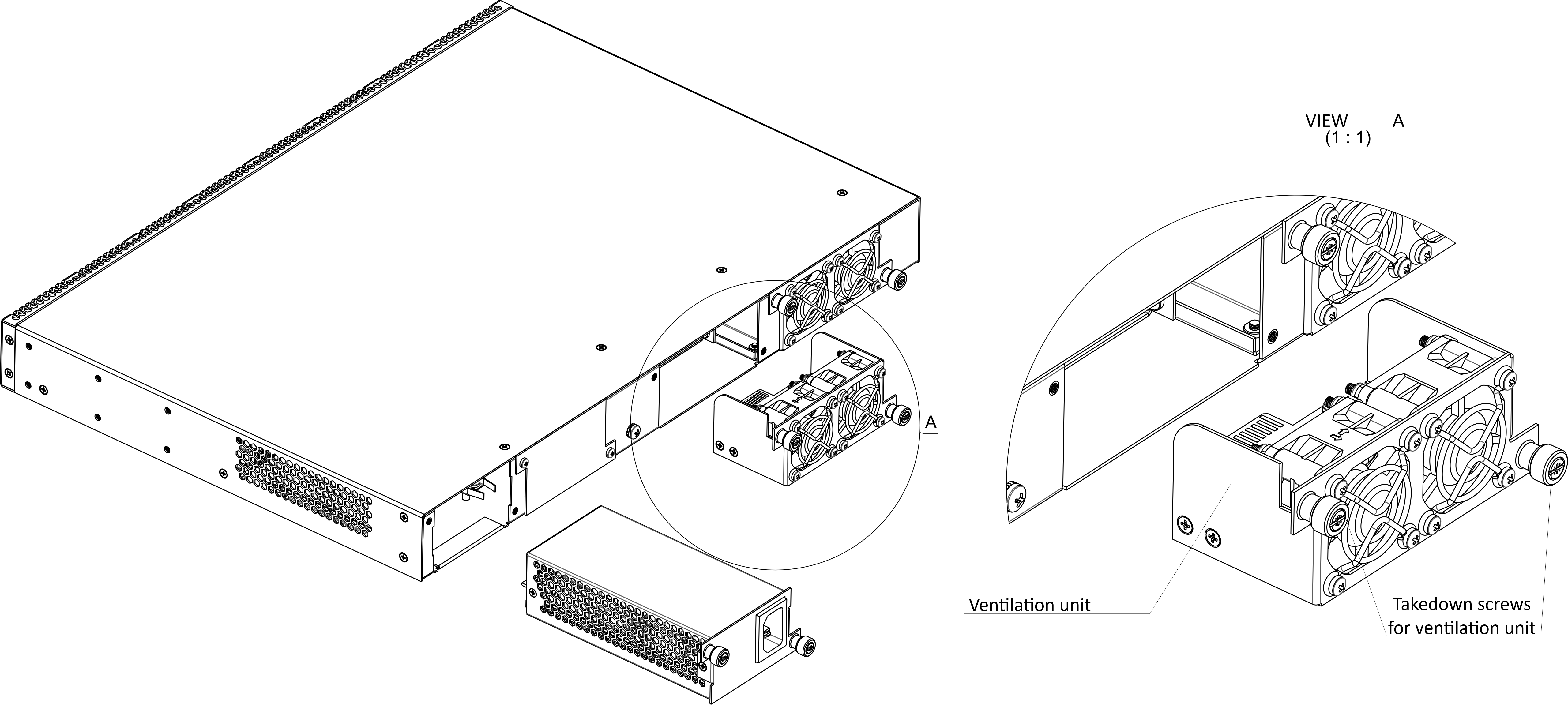
Figure 35 – Ventilation unit. Installation to the case
To remove a ventilation unit:
- Step 1. Use a screwdriver to remove the screws for securing the ventilation unit on the rear panel (Figure 35).
- Step 2. Carefully pull the unit until it is removed from the case.
To install a ventilation unit:
- Step 1. Insert the unit into the terminal case.
- Step 2. Fix the ventilation unit on the rear panel with screws (Figure 35).
Power module replacement
The design of the terminal provides the possibility of replacing one of the power supply units without disconnecting power to the second.
To remove a ventilation unit:
- Step 1. Use a screwdriver to remove the right screw fixing the power supply unit to the rear panel (see Figure 35).
- Step 2. Carefully pull the unit until it is removed from the case.
To install a ventilation unit, perform the following actions:
- Step 1. Insert the unit into the device housing until you hear it click into place.
- Step 2. Secure the power supply unit to the rear panel with the mounting screws (Figure 35).
OLT firmware update
This section describes the terminal firmware update procedure. To download a firmware file, use the TFTP server available in the terminal management network. The device has two areas for firmware files, with the ability to boot from the selected one.
- Step 1. Copy the firmware file into the root folder (or any other known folder) of the TFTP server.
- Step 2. Update the firmware by using the copy command.
copy tftp://192.168.1.5/ltp-16n-1.5.1-build50.fw.bin fs://firmware
- Step 3. To view the firmware versions in the sections, use the show firmware command.
LTP-16N# show firmware Image Running Boot Version Build Commit Date ----- ------- ---- ------- ----- -------- ---------------- 1 yes * 1.5.0 682 139f1d2c 17.03.2023 10:12 2 no 1.5.1 50 ddd36dcc 10.04.2023 12:09
- Step 4. Select the section that will be applied after reboot.
LTP-16N# firmware select-image alternate
- Step 5. Reboot the device.
LTP-16N# reboot
The list of changes
Firmware version | Document version | Issue date | Revisions |
|---|---|---|---|
| 1.7.0 | Issue 11 | 06.12.2023 | Synchronization with firmware version 1.7.0 Sections added:
|
| 1.6.3 | Issue 10 | 31.10.2023 | Synchronization with firmware version 1.6.3
|
| 1.6.2 | Issue 9 | 30.09.2023 | Synchronization with firmware version 1.6.2 Added support for LTP-8N |
| 1.6.0 | Issue 8 | 14.08.2023 | Synchronization with firmware version 1.6.0 Sections added:
Sections changed:
|
| 1.5.1 | Issue 7 | 31.05.2023 | Synchronization with firmware version 1.5.1 Added support for LTX-8(16) |
| 1.5.0 | Issue 6 | 28.04.2023 | Synchronization with firmware version 1.5.0 Sections added:
Sections changed:
|
| 1.4.0 | Issue 5 | 22.07.2022 | Synchronization with firmware version 1.4.0 Sections added:
Sections changed:
|
| 1.3.1 | Issue 4 | 28.02.2022 | Synchronization with firmware version 1.3.1 |
| 1.3.0 | Issue 3 | 02.11.2021 | Sections added:
|
1.2.0 | Issue 2 | 28.05.2021 | Synchronization with firmware version 1.2.0 |
1.0.0 | Issue 1 | 30.11.2020 | First issue |
| Firmware version | 1.7.0 | ||