Subscriber Terminals
NTX-1, NTX-1F
Firmware Version 1.0.0
IP address: http://192.168.1.1
Usename: user
Password: user
Introduction
The XGS-PON network belongs to one of the varieties of passive optical networks PON. This is one of the most modern and effective solutions to the problems of the 'last mile', which allows significant savings on cable infrastructure and provides information transfer speeds of up to 10 Gbps in the downlink direction and 10 Gbps in the uplink direction. Using solutions based on XGS-PON technology in access networks makes it possible to provide the end user with an access to a set of services based on the IP protocol along with traditional services.
The main advantage of XGS-PON is the use of a single station terminal (OLT) for multiple subscriber devices (ONT). OLT is a converter of Gigabit Ethernet and XGS-PON interfaces, which serves to connect the PON network with higher-level data transmission networks. ONT is designed to connect customers' terminal equipment to broadband access services. It can be used in residential complexes and business centers.
The line of ONT NTX equipment manufactured by ELTEX is represented by terminals:
- NTX-1 with two UNI (user network interfaces) Ethernet interfaces: RJ-45 10/100/1000BASE-T port, RJ-45 100/1000/2.5G/5G/10GBASE-T port; and one XGS-PON port;
- NTX-1F with two UNI (user network interfaces) Ethernet interfaces: RJ-45 10/100/1000BASE-T port, 10GbE (SFP+) port; and one XGS-PON port.
This user manual describes purpose, main technical characteristics, rules for configuring, monitoring, and firmware updating of optical terminals NTX-1, NTX-1F.
Notes and warnings
Notes contain important information, tips or recommendations on device operation and setup.
Warnings inform users about hazardous conditions which may cause injuries or device damage and may lead to the device malfunctioning or data loss.
Product Description
Purpose
The NTX-1, NTX-1F XGS-PON ONT (10-Gigabit-capable Symmetric Passive Optical Network) devices are high-performance subscriber terminals designed to communicate with higher-level equipment of passive optical networks and provide broadband access services to the end user. Communication with XGS-PON networks is implemented through the XGS-PON interface, interfaces 10/100/1000BASE-T, 100/1000/2.5G/ 5G/10GBASE-T (for NTX-1) or 10 GbE Ethernet interface (SFP+) (for NTX-1F) are used to connect client terminal equipment.
The advantage of XGS-PON technology is the optimal use of bandwidth. This technology is the next step to provide new high-speed Internet applications at home and in the office. Designed to deploy a network inside a home or building, these ONT devices provide a reliable, high-bandwidth long-distance connection for users living and working in remote apartment buildings and business centers.
The NTX-1 and NTX-1F devices have the following set of interfaces:
Table 1. Interface configuration
| Model name | WAN | LAN |
|---|---|---|
NTX-1 | 1 × XGS-PON | 1 × 100/1000/2.5G/5G/10GBASE-T 1 × 10/100/1000BASE-T |
NTX-1F | 1 × XGS-PON | 1 × Ethernet 10GbE (SFP+) 1 × 10/100/1000BASE-T |
Overview
The device has the following interfaces:
- 1 XGS-PON port for connection to the provider's network;
- 1 RJ-45 10/100/1000BASE-T port for network devices connection;
- 1 RJ-45 100/1000/2.5G/5G/10GBASE-T port (for NTX-1) or 1 Ethernet port 10GbE (SFP+) (for NTX-1F) for network devices connection.
The terminal is powered via 220 V/12 V external adapter.
The device supports the following functions:
- Network functions:
- operation in 'bridge' mode;
- IGMP snooping support.
- firmware update via the web interface, OMCI;
- remote monitoring, configuration and setup via OMCI.
Figure 1 below shows use case of NTX-1, NTX-1F.
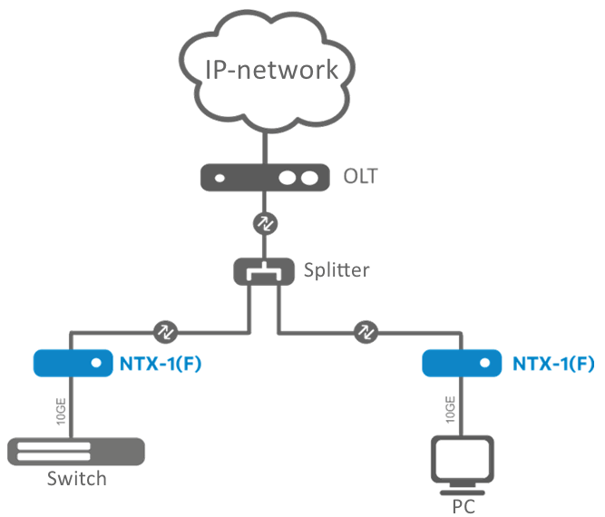
Fig. 1. NTX-1, NTX-1F Use Case
Technical Specifications
Table 2 lists main specifications of the terminal.
Table 2. Main Specifications
Ethernet LAN interfaces parameters
| Device | NTX-1 | NTX-1F |
|---|---|---|
| No. of interfaces | 2 | 2 |
| Electrical port | 1 × 10/100/1000BASE-T (RJ-45) 1 × 100/1000/2.5G/5G/10GBASE-T (RJ-45) | 1 × 10/100/1000BASE-T (RJ-45) 1 × Ethernet 10GbE (SFP+) |
| Data transfer rate | Autonegotiation, 10/100/1000/10000 Mbps, duplex/half duplex | Autonegotiation, 1000/10000 Mbps, duplex/half duplex |
| Supported standards | IEEE 802.3i 10BASE-T Ethernet IEEE 802.3u 100BASE-TX Fast Ethernet IEEE 802.3ab 1000BASE-T Gigabit Ethernet IEEE 802.3bz 2.5G/5GBASE-T Gigabit Ethernet IEEE 802.3ae 10GBASE-T 10Gigabit Ethernet IEEE 802.3x Flow Control IEEE 802.3 NWay Autonegotiation | IEEE 802.3i 10BASE-T Ethernet IEEE 802.3u 100BASE-TX Fast Ethernet IEEE 802.3ab 1000BASE-T Gigabit Ethernet IEEE 802.3ae 10GBASE-T 10Gigabit Ethernet IEEE 802.3x Flow Control IEEE 802.3 NWay Autonegotiation IEEE 802.3z Fiber Gigabit Ethernet |
PON Interface Parameters
| No. of interfaces | 1 |
|---|---|
| Supported standards | ITU-T G.9807.1 XGS-PON |
Control
| Local control | web interface |
|---|---|
| Remote control | OMCI |
| Firmware version updating | OMCI, HTTP |
| Access restriction | by password |
General parameters
| Power supply | 12 V, 2 A power adapter | ||
|---|---|---|---|
| Power consumption | up to 10 W | ||
| Operating temperature | from +5 to +40 °C | ||
| Relative humidity | up to 80 % | ||
| Dimensions (W × H × D) | 234 × 34 × 133 mm (NTX-1) 234 × 36 × 135 mm (NTX-1F) | ||
| Lifetime | at least 5 years |
Design
NTX-1 Rear Panel
The subscriber terminal is enclosed in a plastic case with dimensions of 234 × 34 × 133 mm.
The rear panel of NTX-1 is shown in Figure 2 below.

Fig. 2. NTX-1 Rear Panel Layout
Connectors and controls located on NTX-1 rear panel are listed in Table 3.
Table 3. Description of connectors and controls of NTX-1 rear panel
| No. | Rear Panel Element | Description |
|---|---|---|
| 1 | F | Reset to default settings |
| 2 | ON/OFF | ON/OFF switch |
| 3 | 12V | Power adapter connector |
| 4 | 1G/10G | RJ-45 100/1000/2.5G/5G/10GBASE-T port for network devices connection |
| 5 | 1G | RJ-45 10/100/1000BASE-T port for network devices connection |
| 6 | PON | SC/APC connector (socket) XGS-PON optical interface GPON |
NTX-1F Rear Panel
The subscriber terminal is enclosed in a plastic case with dimensions of 234 × 36 × 135 mm.
The rear panel of NTX-1F is shown in Figure 3 below.

Fig. 3. NTX-1F Rear Panel Layout
Connectors and controls located on NTX-1F rear panel are listed in Table 4.
Table 4. Description of connectors and controls of NTX-1F rear panel
| No. | Rear Panel Element | Description |
|---|---|---|
| 1 | F | Reset to default settings |
| 2 | ON/OFF | ON/OFF switch |
| 3 | 12V | Power adapter connector |
| 4 | 1G/10G | 10 GbE Ethernet port (SFP+) for network devices connection |
| 5 | 1G | RJ-45 10/100/1000BASE-T port for network devices connection |
| 6 | PON | SC/APC connector (socket) XGS-PON optical interface GPON |
NTX-1, NTX-1F Light Indication
The front panel of NTX-1, NTX-1F is shown in Figure 4 below.
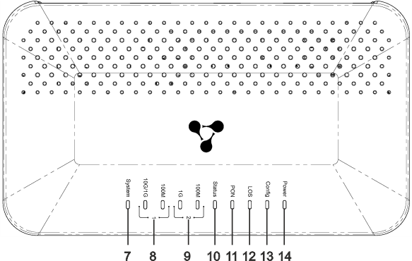
Fig. 4. NTX-1, NTX-1F Front Panel Layout
LED indicators located on NTX-1, NTX-1F front panel represent the current state of the device.
Table 5 below lists possible states of the LEDs.
Table 5. Description of NTX-1, NTX-1F front panel indicators
| No. | Front Panel Element | Indicator State | Description |
|---|---|---|---|
7 | System | Off | The Linux system did not start |
| On | The Linux system started successfully | ||
| Flashing | Updating via OMCI | ||
| 8 | LAN 1 10G/1G indicator | Off | Cable is not connected |
| Yellow | 1/10 Gbps connection has been established | ||
| Flashing yellow | Data transfer is in progress | ||
| LAN 1 100M indicator | Off | Cable is not connected | |
| Green | 100 Mbps connection has been established | ||
| Flashing green | Data transfer is in progress | ||
9 | LAN 2 1G indicator | Off | Cable is not connected |
| Yellow | 1 Gbps connection has been established | ||
| Flashing green | Data transfer is in progress | ||
| LAN 2 100M indicator | Off | Cable is not connected | |
| Green | 100 Mbps connection has been established | ||
| Flashing green | Data transfer is in progress | ||
| 10 | Status | Off | An error occurred during OMCI configuration progress |
| Green | The OMCI configuration has completed successfully, the device is in operation | ||
| Flashing green | OMCI configuration obtaining is in progress | ||
11 | PON | Off | Optic cable is not connected/laser is disabled on OLT side |
| Green | The device is connected and registered on OLT | ||
| Flashing green | Registration on OLT is in progress | ||
| 12 | LOS | Off | Signal from OLT present |
| Red | Optic cable is not connected | ||
| Flashing red | Laser is disabled on OLT side | ||
| 13 | Config | Off | Standard configuration is set |
| Green | Not standard configuration is set | ||
14 | Power | Off | The device is unplugged or faulty |
| Green | Power on |
Reboot/Reset to Factory Settings
To restart the device, press the 'F' button once on the bottom panel of the device. To boot the device with factory settings, press and hold the 'F' button for 5 seconds, then release. The device will reboot. Factory settings: LAN IP address is 192.168.1.1, subnet mask is 255.255.255.0. Access is possible from LAN 1 and LAN 2 ports.
Delivery Package
The basic delivery of the NTX-1, NTX-1F device includes:
- Subscriber terminal;
- 220/12 V, 2 A power adapter;
- Installation and initial configuration guide.
Device Architecture
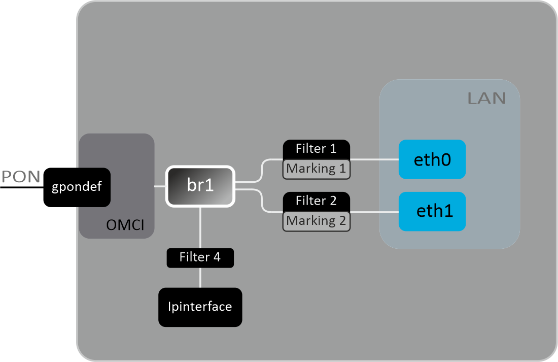
Fig. 5. Logical architecture of the device with factory configuration
Main elements of the device:
- Optical transceiver (BOSA) is designed to convert an optical signal into an electrical one;
- Processor (PON chip) is a converter of Ethernet and XGS-PON interfaces.
With the factory (initial) configuration, the following logical blocks are present in the device (Figure 5):
- Br0;
- eth0…1;
- IPInterface1.
In this case, the br0 block is designed to combine LAN ports into one group.
Eth0..1 blocks are Ethernet ports with an RJ-45 connector for connecting PCs, STB or other network devices. They are logically included in the br0 block.
The Filter and Marking blocks are designed to include local interfaces in one group (in the br0 block). They are responsible for traffic rules: Filter blocks are responsible for incoming traffic on the interface, Marking blocks are responsible for outgoing traffic.
The IPInterface block is a logical object on which the IP address for access to the local network is located.
Configuring the Device via Web Interface. User Access
Getting started
To configure the device, you need to connect to it via a web browser:
- Open a web browser (hypertext document viewer), for example, Firefox, Google Chrome.
- Enter the device IP address in the browser address bar.
Default IP address of the device is 192.168.1.1; subnet mask is 255.255.255.0.
When the device is successfully detected, username and password request page will be shown in the browser window:

3. Enter username and password into the corresponding fields.
UserName is user, password is user.
4. Click the ‘Login’ button. The starting page of the device's web interface will be displayed in the browser window.
Web interface elements
General view of the device configuration window is shown below.
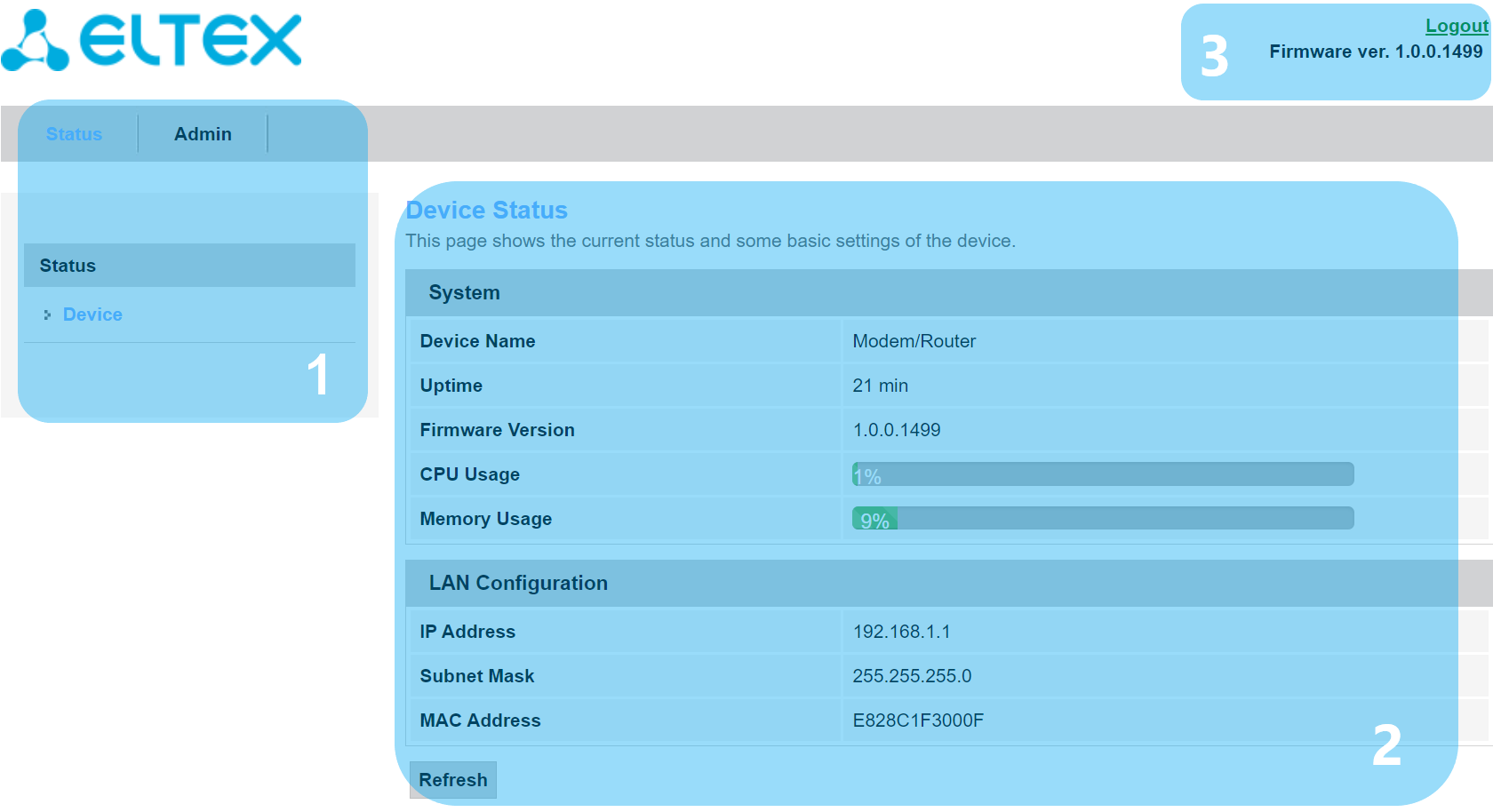
The user interface window can be divided into 3 parts:
- The navigation tree for the device settings menu.
- The main window of selected section settings.
- User change button.
'Status' Menu. Device Information
'Device Status' Submenu. General Information on the Device
The section displays general information on the device, main parameters of LAN and WAN interfaces.
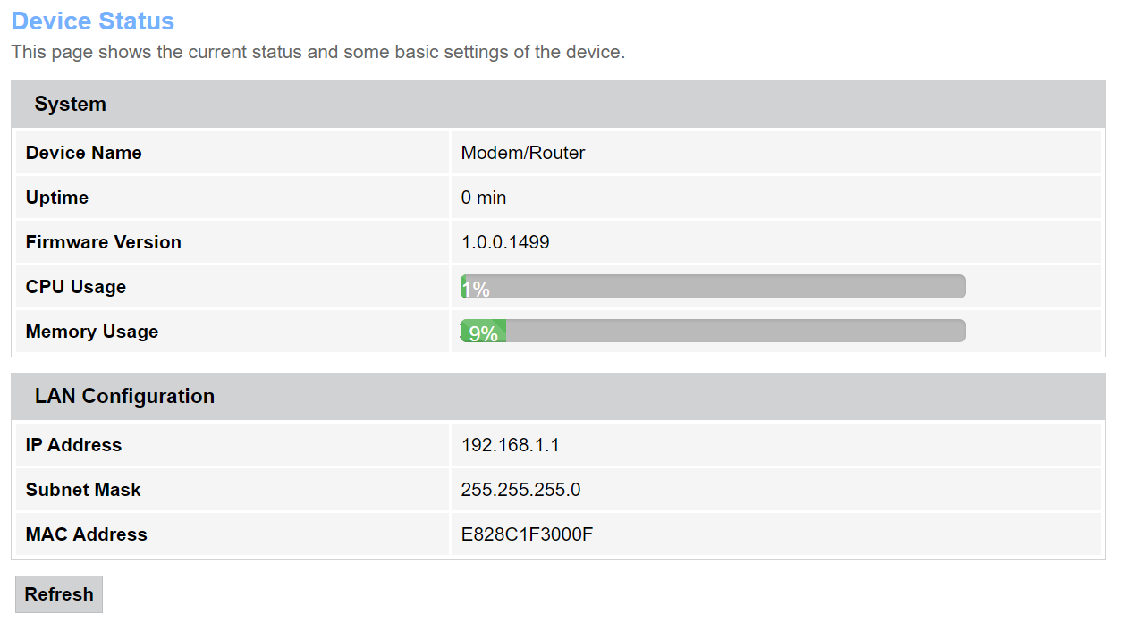
The following settings are shown:
System
- Device Name;
- Uptime — device operation time since the last reboot;
- Firmware Version;
- CPU Usage, %;
- Memory Usage, %.
LAN Configuration
IP Address;
Subnet Mask;
MAC Address.
To update the data on the page, click the 'Refresh' button.
'Admin' Menu
This is device management section. In this menu, you can set passwords, time, configurations, and more.
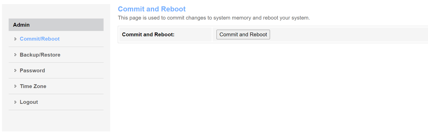
'Commit/Reboot' Submenu. Commit Changes and Reboot the Device
Click the 'Commit and Reboot' button to reboot the device or to save changes to the system memory. It may take several minutes to reboot the device.
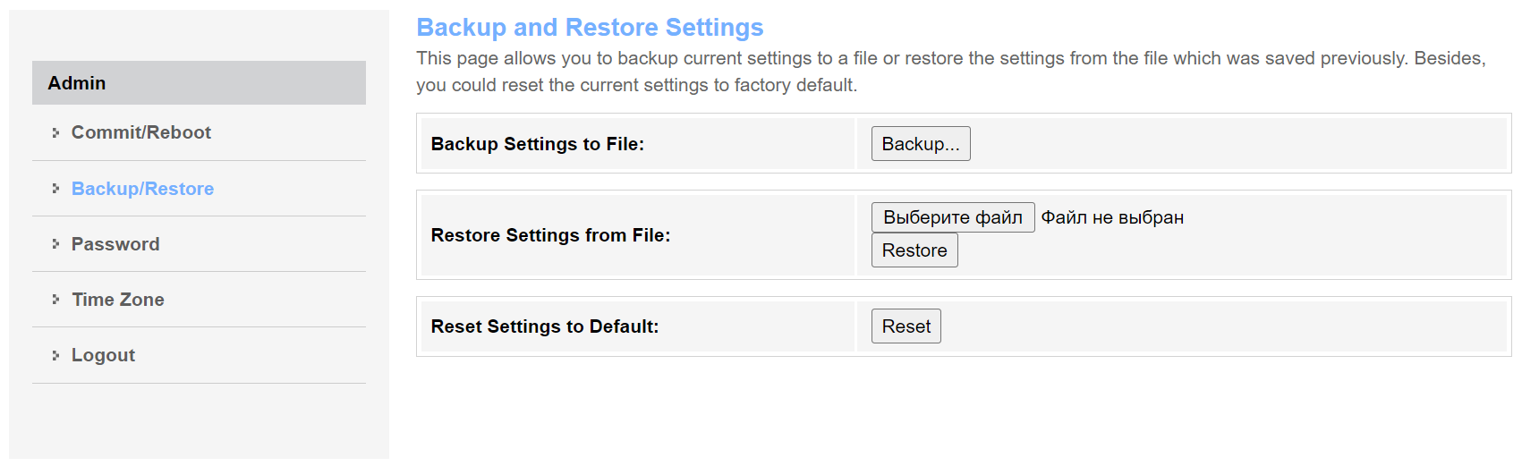
'Backup/Restore' Submenu. Backup and Restore Settings
In the section, you can:
- Copy the current settings to a file (Backup Settings) by clicking on the 'Backup Settings to File' button;
- Restore settings from a file that was saved earlier (Update Settings) by clicking on the 'Restore' button;
- Reset the current settings to factory default settings (Restore Default) by clicking on the 'Reset Settings to Default' button.
'Password' Submenu. Setting up Access Control
In the section, you may change the password for access to the device.
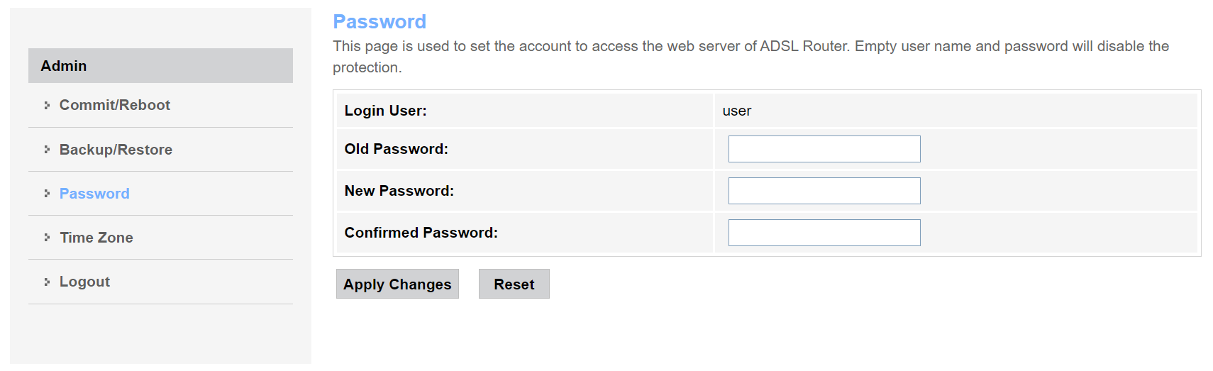
To change the password, enter the current password into the Old Password field, then enter the new password into the New Password and the Confirmed Password fields.
To accept and save changes, click the 'Apply Changes' button, to reset the data, click the 'Reset' button.
'Time Zone' Submenu. System Time Configuration
In the section, you may configure system time. Synchronization with Internet servers of the exact time is also available.
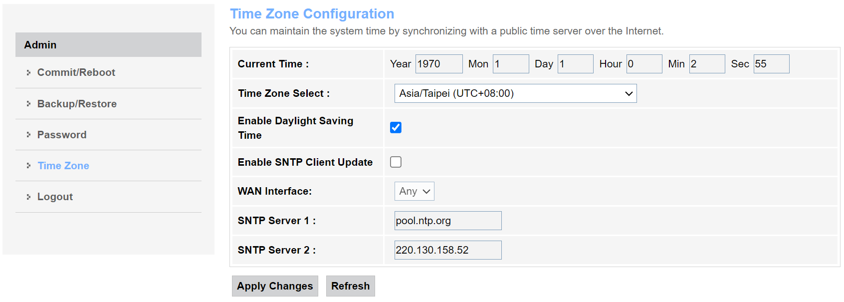
The following settings are available:
- Current time;
- Time Zone Select;
- Enable Daylight Saving Time;
- Enable SNTP Client Update — enable SNTP time synchronization;
- WAN Interface — interface via which the time is updated;
- SNTP Server 1 — preferred time server;
- SNTP Interval 2 — synchronization interval with the NTP server.
To save changes, click the 'Apply Changes' button, and to update the information, click the 'Refresh' button.
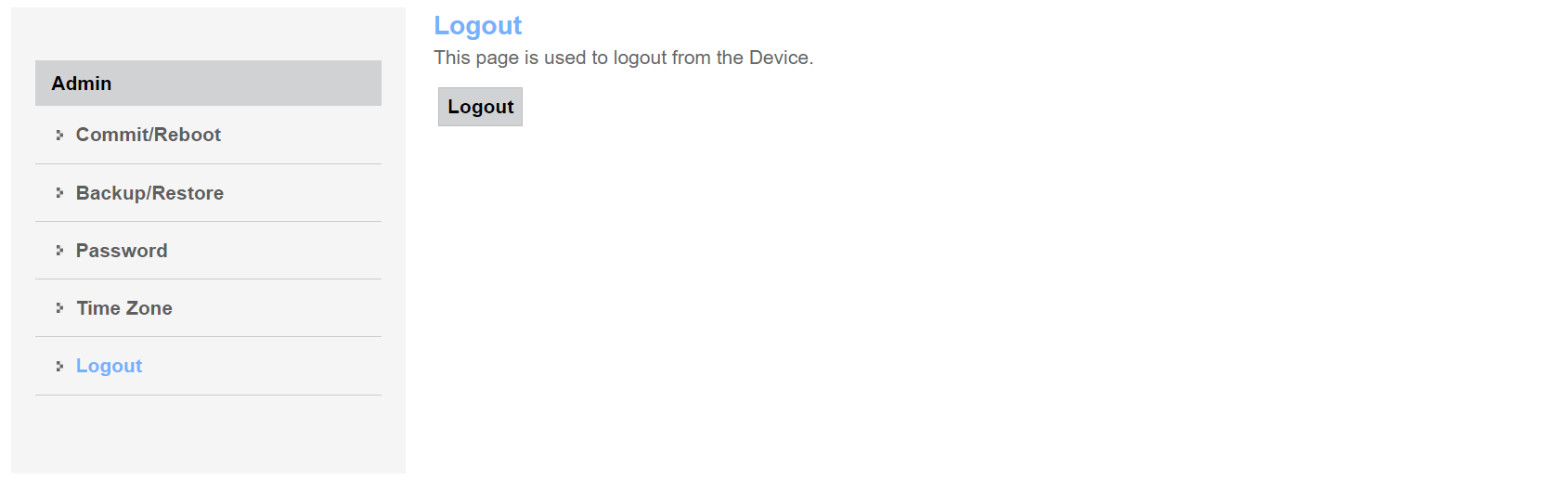
'Logout' Submenu. User Change
In the section, you can access the authorization menu and select another account.
Revisions
Document version | Firmware | Issue date | Revisions |
|---|---|---|---|
Version 1.0 | 1.0.0 | 06.2021 | First issue |