User station
WB-2P-LR5
User manual, Firmware version 2.6.0
IP address: http://192.168.1.1
Username: admin
Password: password
Introduction
Annotation
Modern tendencies of telecommunication development necessitate operators to search for the most optimal technologies, allowing you to satisfy drastically growing needs of subscribers, maintaining at the same time consistency of business processes, development flexibility and reduction of costs of various services provision. Wireless technologies are spinning up more and more and have paced a huge way for a short time from unstable low-speed communication networks of low radius to broadband networks equitable to speed of wired networks with high criteria for the quality of provided services.
WB-2P-LR5 is a user station designed for connection to Wi-Fi access network which might be constructed using base stations within long distances. The case of WB-2P-LR5 is sealed, that is allows to install the device outdoor with different climate conditions.
This manual specifies intended purpose, main technical parameters, design, installation procedure, safe operation rules and installation recommendations for WB-2P-LR5.
Symbols
Notes and warnings
Notes contain important information, tips or recommendations on device operation and setup.
Warnings are used to inform the user about harmful situations for the device and the user alike, which could cause malfunction or data loss.
Device description
Purpose
User station WB-2P-LR5 (herein after 'the device') is designed to provide users with access to secure wireless network.
The device provides access to up-to-date interactive services: Internet, IPTV, VoIP.
WB-2P-LR5 connects to a base station via Wi-Fi technology and operates at 5 and 6 GHz (frequency range of 5830-6150 MHz is supported on WB-2P-LR5 rev.B and rev.C). The device is supposed to operate with WOP-2ac-LR5. WB-2P-LR5 might be also used for wireless bridge organization.
WB-2P-LR5 supports up-to-date requirements to service quality and allows transmitting more important traffic in higher priorities queues. Prioritization is based on QoS technologies: CoS (special tags in VLAN packet field) and ToS (tags in IP packet field).
The device is capable to operate in wide temperature range and in high humidity conditions (parks, factories, stadiums, etc.).
Power to the device is supplied via PoE technology 24V.
Device specification
Interfaces:
- 1 port of Ethernet 10/100/1000BASE-T (RJ-45);
- Wi-Fi 5-6 GHz IEEE 802.11a/n/ac;
- Service Wi-Fi 2.4 GHz 802.11b/g/n (short-range interface for adjustment and device setup during the installation period).1
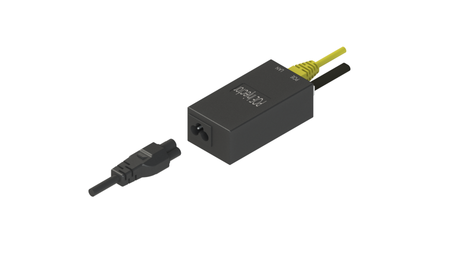
The power is supplied via PoE injector 24V connected to 220 V network.
Use of the injector with voltage different from 24 V will cause the device failure!
1For WB-2P-LR5 rev.C.
Network functions:
- operating in bridge and router modes;
- operating in 'Wi-Fi Station' and 'Wireless bridge' modes;
- support for VLAN Trunk;
- support for Management VLAN;
- support for General VLAN;
- support for Transparent Mode;
- support for VLAN Mapping;
- static routing;
- support for Transparent wireless bridge function;
- support for PPPoE client;
- time synchronization via NTP;
- support for static address and DHCP (DHCP client on WAN side, DHCP server on LAN side);
- support for DNS;
- support for D-DNS;
- support for NAT;
- support for UPnP;
- firewall;
- support for cloning of MAC address on WAN interface;
- support for quality of service mechanisms (QoS through DSCP and 802.1P);
- support for IPTV functions (IGMP-proxy, UDP-to-HTTP proxy);
- support for MVR;
- support for limiting the number of MAC addresses learned (MAC-learninig);
- firmware update via web interface;
- support for DHCP-based autoprovisioning;
- support for TR-069;
- remote monitoring, configuration and setup: SNMP, web interface, Telnet, SSH.
The figures below illustrate applications schemes of WB-2P-LR5.
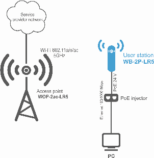
Functional scheme of using WB-2P-LR5 without router
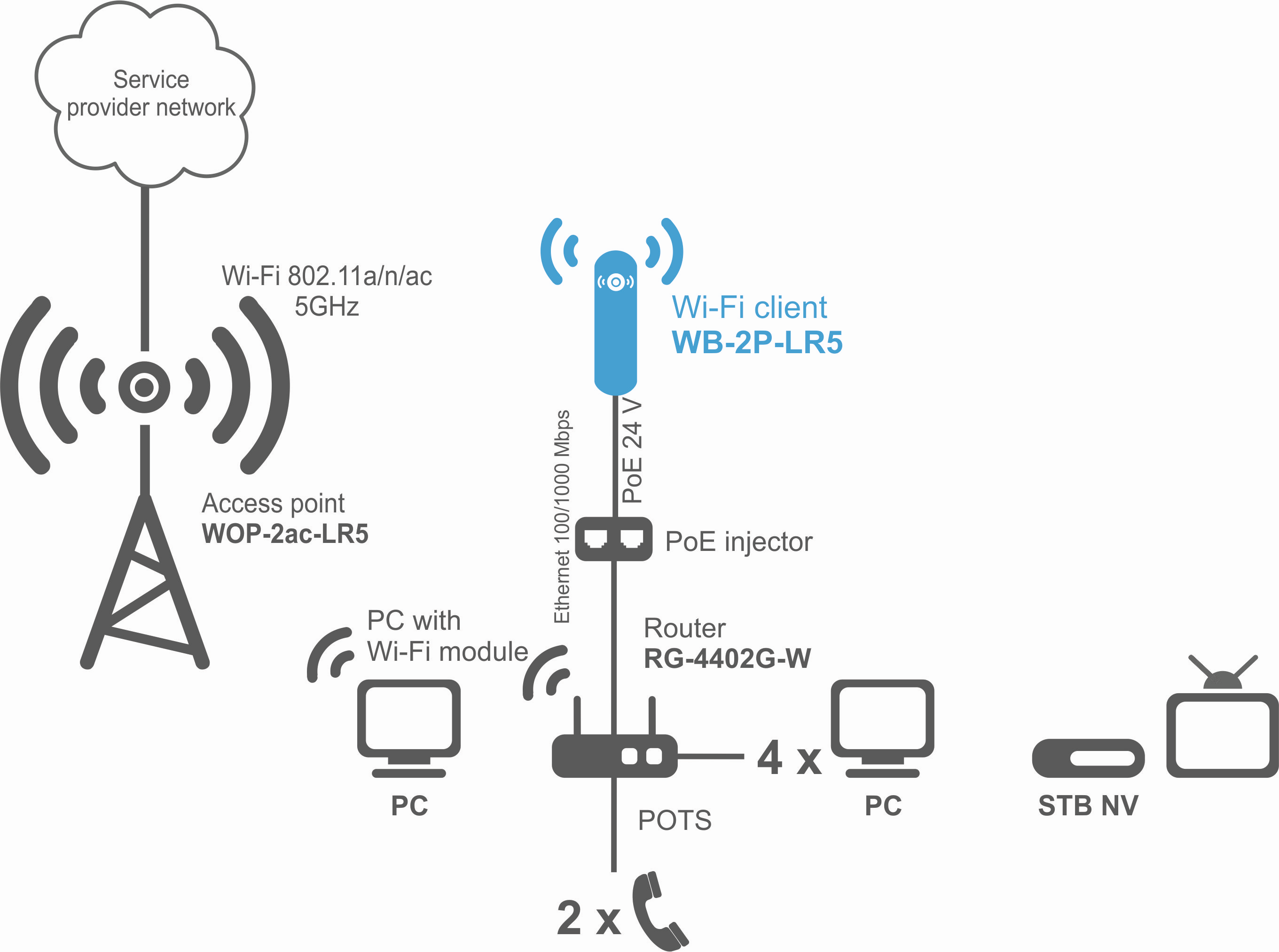
Functional scheme of using WB-2P-LR5 with router

Functional scheme of using WB-2P-LR5 for wireless bridge organization
Technical features
Table 1 shows main specifications of the device.
Table 1 — Main specifications
LAN Ethernet interface parameters | |
|---|---|
Number of ports | 1 |
Electrical connector | RJ-45 |
Data rate, Mbps | 10/100/1000, auto-negotiation |
Standards | BASE-T |
Wireless interface parameters | |
Standards | 802.11a/n/ac |
Frequency range, MHz | 5180–5825 MHz 5180–6150 MHz (for WB-2P-LR5 rev.B, WB-2P-LR5 rev.C) |
Modulation | BPSK, QPSK, 16QAM, 64QAM, 256QAM |
Speed of data transmission, Mbps | 802.11a: up to 54 Mbps |
Maximum output power of the transmitter | 5–6 GHz: 24 dBm (for WB-2P-LR5, WB-2P-LR5 rev.B) 28 dBm (for WB-2P-LR5 rev.C) |
Receiver sensitivity | 5-6 GHz: -94 dBm |
Security | 64/128/152 bit WEP encryption, WPA/WPA2, |
Antenna parameters | |
Gain | 2x12 dBi |
Polarization | dual-polarized antenna |
Beam angle (horizontal polarization) | 60° |
Beam angle (horizontal polarization) | 15° |
SWR | 2.0:1 |
Impedance | 50 Ohm |
Front to back ratio | > 20 dB |
Control | |
Remote control | Web interface, Telnet, SSH, SNMP (monitoring), TR-069 |
Access restriction | by password |
General parameters | |
RAM | 128 MB |
Flash | 32 MB |
Power supply | Passive PoE 24 V |
Power consumption | no more than 8 W |
range of operation temperatures | from -45 to +65 °С |
Operating humidity | up to 95% |
Ingress Protection Rating | IP54 |
Dimensions (WxHxD) | 80x282x66 mm |
Weight | 0.35 kg |
Design
WB-2P-LR5 housed in a plastic case in industrial design. The dimensions of the device are 80x282x66 mm.
The device appearance is shown in the figure below.

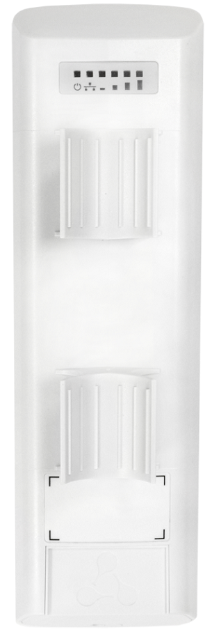
WB-2P-LR5 layout
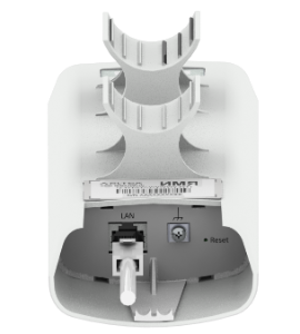
LAN port 10/100/1000BASE-T (RJ-45 connector) for local network connection and power supply via PoE, a grounding connector (for WB-2P-LR5 rev.C) and the button for resetting to factory settings ('Reset') are located on the bottom panel of the device.
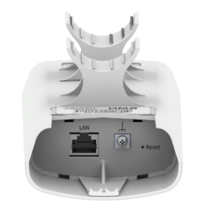
WB-2P-LR5 bottom panel elements
Light indication
The light indication panel of WB-2P-LR5 is shown below.
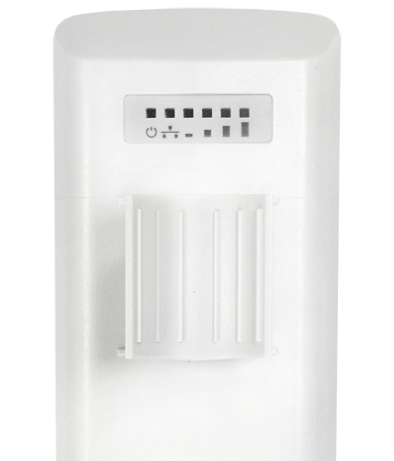
WB-2P-LR5 light indication panel
The current state of the device is shown with the help of light indicators located on the back panel of WB-2P-LR5. The list of indicators and their description is shown in the table below.
Table 2 – Description of rear panel LED indicators
Indicator | Indicator state | Description | |
|---|---|---|---|
| Power – power and operation status indicator | solid green | the device power supply is enabled, normal operation |
solid orange | the device is loaded but IP address is not received via DHCP | ||
solid red | the device is loading | ||
| LAN – LAN interface indicator | solid green (10, 100 Mbps)/ | the channel between LAN interface of WB-2P-LR5 and connected device is active |
flashes | packet data transmission between LAN interface of WB-2P-LR5 and connected device | ||
| WLAN – received signal strength indicator (RSSI) | solid red | the device is connected to a base statio, the base station signal level is more than -94 dBm |
| solid orange | the device is connected to a base station, the base station signal level is more than -80 dBm | |
| solid green | the device is connected to a base station, the base station signal level is more than -70 dBm | |
| solid green | the device is connected to a base station, the base station signal level is more than -60 dBm | |
none of the indicators is on | the device is not connected to the base station |


Reset to the default settings
There are two ways to reset the device to factory settings:
- Using 'Reset' button on the device. When the device is loaded, press and hold 'Reset' button located on the bottom panel (approximately 10–15 seconds) until 'Power' indicator is flashing orange;
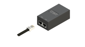
- Using PoE injector supplied with the device. When the device is loaded, press and hold 'RST' button of the injector (approximately 10–15 seconds) until 'Power' indicator is flashing orange.
Device will be rebooted automatically. DHCP client will be launched by default. If the address is not received via DHCP the device will have IP address — 192.168.1.1, subnet mask — 255.255.255.0; User Name/Password to access via Web interface — admin/password.
Delivery package
The basic supply package of WB-2P-LR5 includes:
- User station WB-2P-LR5;
- Mounting kit: 2 clamps for attaching;
- PoE injector 24 V;
- Patch cord RJ-45, 5e cat. 1.5 m;
- Cord for europlug - C13-F-1.8 m;
- Sheet with light indication description;
- Technical passport.
A bracket with horizontal and vertical adjustment might be included to the supply package upon a request.
Installation order
This section defines safety rules, installation recommendations, setup procedure and the device starting procedure.
Safety rules
- Do not open the device case. There are no user serviceable parts inside.
- Do not install the device during a thunderstorm. There is a risk of lightning stroke.
- Follow requirements for voltage, current and frequency specified in the user manual.
- Measuring devices and computer must be grounded before connecting to the device. The electric potential difference between devices cases should not exceed 1 V.
- Make sure that all the cables are intact and they are reliably attached to connectors.
- You should satisfy established standards and requirements for working at height during the device installation on the high-rise constructions.
- The device exploitation should be performed by specially prepared engineering and technical personnel.
- Connect only to operational service equipment.
Installation recommendations
- Recommended location for device installation: communications mast/pole.
- Before you install and enable device, check the device for visible mechanical defects. If defects are observed, you should stop the device installation, draw up corresponding act and contact the supplier.
- Install the device on communications mast/pole so that the device is directed to base station sectoral antenna as much as possible. There must also be direct visibility to the base station.
- In order to provide better receiving signal level, the sectoral antenna of a base station should be in line of sight of WB-2P-LR5. You can achive the highest signal level by antenna alignment with the help of RSSI indicators.
- The transmitting part of the device is located on the other side from brackets. This area should be directed to base station sectoral antenna.
After adjusting, make sure that level of the received signal from the base station should be no more than -65 ÷ -70 dBm. Decreasing this level up to -75 dBm is permitted if it does not involve the use of VoIP, streaming video and other traffic that is sensitive to losses in a wireless network.
Recommendations for lightning protection
- The grounding shall be made with insulated stranded wire. The grounding device and the cross-section of the grounding wire must comply with the requirements of the Electrical Code of Practice.
- The first outdoor lightning protection should be installed as close as possible to the base station, connecting them with a short outdoor FTP cable with shielded connectors.
- The second outdoor lightning protection should be installed as close as possible to the PoE switch (PoE injector), connecting them with a short outdoor FTP cable with shielded connectors.
- The lightning protectors are connected to each other by an outdoor FTP cable up to 100 m long.
- It is necessary to ground the base station (for more information, see Mounting the device).
- The PoE switch (PoE injector) must be connected to a 220V electrical outlet with ground or grounded through the housing.
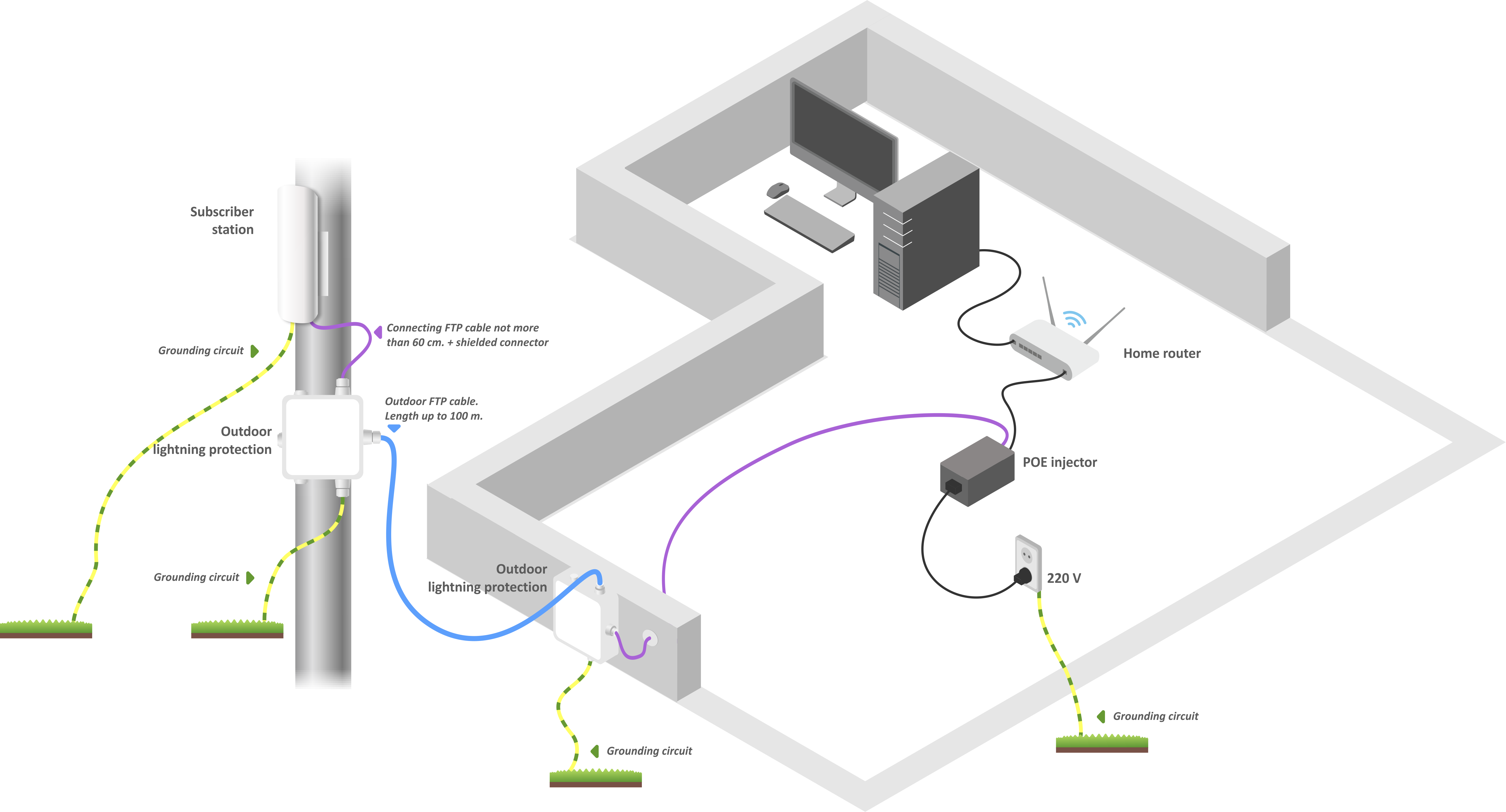
Wiring diagram of the subscriber station to provide lightning protection
WB-2P-LR5 mounting
There are two mounting options for the WB-2P-LR5 subscriber station: mounting of the device directly on the pipe rack and mounting on the pipe rack using a bracket.
Preparing the device for operation
1. Remove the bottom cover which closes LAN-port. Ground the device through a grounding connector located to the tight of LAN port (for WB-2P-LR-5 rev.C).

3. Connect Ethernet cable to LAN port.
4. Close the bottom cover.
Switching on the device
1. Connect Ethernet cable from WB-2P-LR5 to PoE port of injector.
2. Connect Ethernet cable of your LAN network or PC to LAN port of PoE injector.
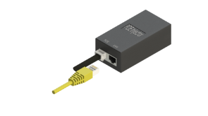
3. Connect PoE injector to 220 V socket with the help of power line cord. After turning the power on, the device will load within a minute.
4. Connect to web browser via web interface of the WB-2P-LR5 following the instructions given in the Device management via web configurator section.
5. If this is the first launch of the device, proceed to the Preconfiguration section.
Preconfiguration
Before mounting, preconfigure the device.
- Make sure that the power is supplied.
- Follow the algorithm from the Configuration example section.
Make sure that user station connects to the right wireless network: signal strength indicators are on. Description of the LED indicators are given in the Light indication section.
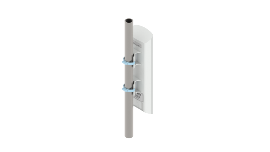
Mounting the device on a mast/pole
- Connect to the network and preconfigure the device following the instructions from the Preconfiguration section. Then power off the device and proceed to the mounting.
- Install the device on a mast/pole pointing LAN port down as it is shown on the figure below. Attach the device using clamps supplied in the device package. Follow the safety rules and recommendations given in Safety rules and Installation recommendations.
3. Connect to the network following the instructions given in the Preparing the device for operation and Switching on the device (steps 1-3). Next, proceed to the device antenna alignment.
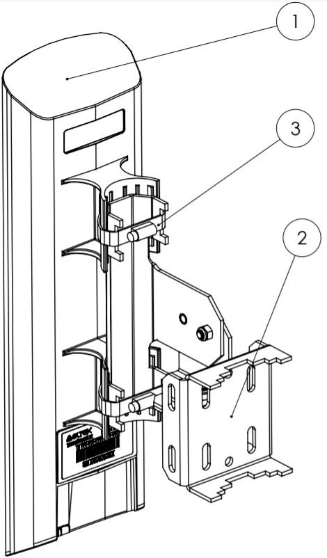
Mounting the device using a bracket
1. Attach the bracket to the desired surface.
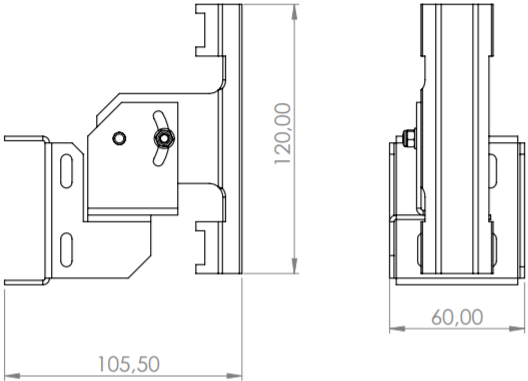
2. Fasten the device (1) to the bracket (2) and lock it with the clamps (3) as shown in the figure below.
Bracket dimensions
Switching on
- Plug the injector into 220 V outlet. Connect a PC to LAN port of the injector.
WB-2P-LR5 loads in a minute after switching on. Connect to the web configurator of WB-2P-LR5 through a browser.
IP address by default: 192.168.1.1.
Username: admin, password: password.- Network configuration is described in The 'Network' menu section.
Wi-Fi antenna alignment
For ease of antenna alignment the Service Wi-Fi is implemented in the device (only for WB-2P-LR5 rev.C). It allows to connect the wireless client to the "EltexWiFi" SSID (2.4 GHz frequency band) and align antennas using data of monitoring of the connection parameters of the subscriber station WB-2P-LR5 with the base station in web interface.
- Connect the smartphone to a Wi-Fi network using the EltexWiFi SSID.
- Set the following connection settings on the smartphone: Static IP address – 192.0.2.X; netmask – 255.255.255.0; gateway – 192.0.2.1.
- Open the browser aand enter the address 192.0.2.1:8080. The alignment tab will be displayed, where the signal level from the station to which the WB-2P-LR5 is connected is displayed in real time:
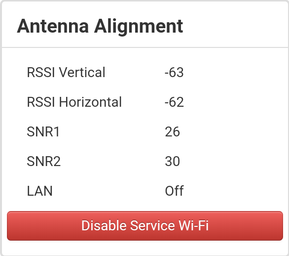
4. Perform the alignment with maximum RSSI.
5. After alignment, you must disable the Service Wi-Fi.
Service Wi-Fi enable/disable through the device’s web configuration is described in the 'Advanced settings' submenu.
Device management via web configurator
Getting started
To start, you need to connect the device through a browser:
- Open a web browser (web-page explorer), for example, Firefox, Opera, Chrome.
- Enter IP-address of the device to the browser address line.
IP address by default: 192.168.1.1, subnet mask: 255.255.255.0. The device is capable to obtain an IP address via DHCP.
If connection is successful, request form with user name and password will be displayed on a browser window.

Factory settings: login: admin, password: password.
3. Enter your username into ‘Login’ and password into ‘Password’ field. Click the ‘Log in’ button. Device Web configurator home page will be opened in the browser window.
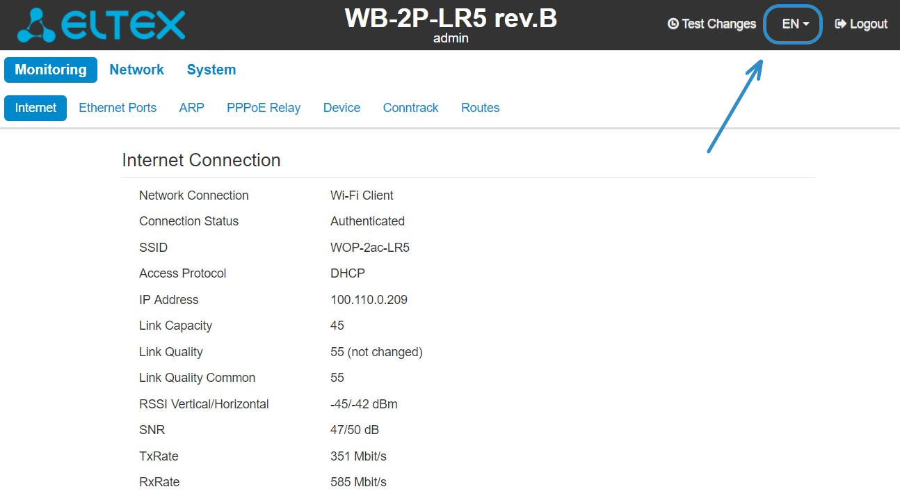
You can select languages on the top-right of the page. Russian and English languages are available.
Changing user
There are two user types for the device: admin and viewer:
- admin(password by default: password) has the full access to the device: read/write any settings, full device status monitoring.
- viewer can only view full device configuration without editing privileges; can access full device status monitoring.
When you click the 'Logout' button, the current user session will be terminated; login window will be displayed:
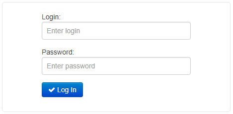
To change the access, you should specify the corresponding username and password and click 'Log' in button.
Applying configuration and discarding changes
Applying configuration
Click 'Apply' to save configuration to flash memory and apply new settings. All the settings come into operation without device rebooting.
The visual indication of the settings applying is realized in the web interface.
The visual indication of the settings applying:Image
State description

After clicking 'Apply', the process of settings saving to device memory is launched. This is indicated by the
 icon in the tab name and on the 'Apply' button.
If the setting are saved successfully, the
 icon will be displayed next to the tab name and on 'Apply' button.
If any parameter value have been set incorrectly, the error notification with description will be displayed after clicking 'Apply' button. The
 mark will be displayed next to the tab name and on 'Apply' button.
The 'Apply' button in the menu.
Discarding changes
You can discard changes only before clicking 'Apply' button. If you click 'Apply' button, all the changed parameters will be applied and saved to device memory. You will not be able to return to previous configuration after clicking 'Apply'.
The button for discarding changes appears as follows:.
Test changes mode
The device has a test mode for a test configuration application.
To activate it, click the 'Test changes' button on the top panel of the web interface.
 Test mode operating time is 300 seconds (5 minutes). During this time you can navigate through the web configurator tabs and make any changes by applying them on each page using the 'Apply' button.
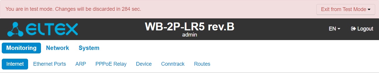
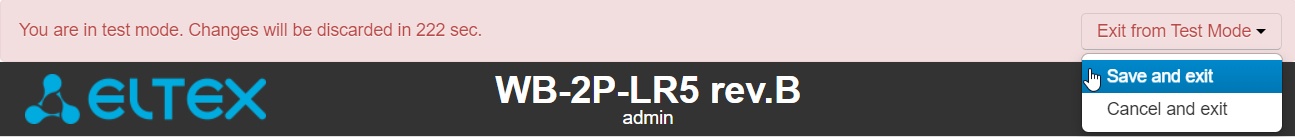
After checking the required configuration, click the 'Exit from Test Mode' button and select the desired action:
- 'Save and exit' – clicking this button will exit the test mode and save to the non-volatile memory all configuration changes that were made and applied in this mode. It will be impossible to undo changes made in the test mode.
- 'Cancel and exit' – clicking will exit the test mode and cancel all changes made in this mode. The configuration in effect on the device before the test mode is activated will be restored.
If the administrator does not exit the test mode within 300 seconds, this will happen automatically along with a rollback of all changes that have been made in this mode. After the specified time, the configuration will be restored even if access to the device is lost as a result of the changes made.
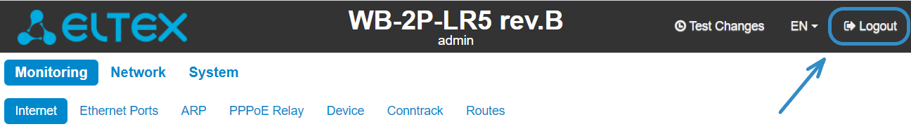
Main elements of the web interface
The figure below shows navigation elements of the web configurator.

The user interface is divided into seven areas:
- Username, which was used to enter the system and 'logout' button to finish the user session.
- Menu tabs which contain submenu tabs are divided into categories: Network, System.
- Submenu tabs manage the settings field below.
- Settings field, which is based on the user select. The field is dedicated to view device settings and setting configuration data.
- Configuration management buttons, the detailed description is given in section Applying configuration and discarding changes.
- Information field. The field contain information on firmware version and web interface version.
The 'Monitoring' menu
To move to the system monitoring mode, select 'Monitoring' on the left panel.
Some pages are not updated automatically. To obtain current state of the device, click ![]()
The 'Internet' submenu
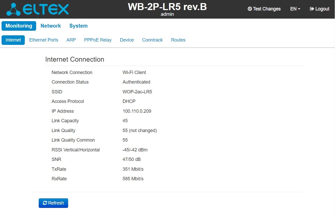
In the Internet submenu, you can view main network parameters of the device.
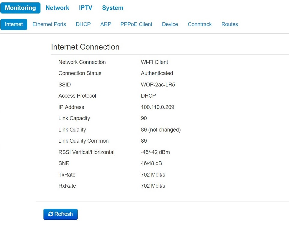
Internet Connection
- Network connection – the parameter shows the type of connection to the external network;
- Connection Status – the parameter shows state of connection to the external network;
- SSID – a name of wireless network, to which the device is connected;
- Access Protocol – a protocol which is used for access to the external network;
- IP Address – device IP address in the external network;
- Link Capacity – parameter that reflects the effectiveness of the use of a modulation by the device on the transmission. It is calculated based on the number of packets transmitted on each modulation, and the reduction factors. The maximum value is 100% (means that all packets are transmitted at maximum modulation for the maximum nss type supported by the device). The minimum value is 2% (in the case when the packets are transmitted to the modulation nss1mcs0 for the device with MIMO 3x3 support). The parameter value is calculated for the last 10 s;
- Link Quality – parameter that displays the status of the link, calculated based on the number of sent retransmit packets. The maximum value is 100% (all transmitted packets were sent on the first attempt), the minimum value is 0% (no packets were successfully sent). The parameter value is calculated for the last 10 s;
- Link Quality Common – parameter that displays the status of the link, calculated based on the number of sent retransmit packets. The maximum value is 100% (all transmitted packets were sent on the first attempt), the minimum value is 0% (no packets were successfully sent). The parameter value is calculated for the entire connection time;
- RSSIVertical/Horizontal – level of signal received from base station, dBm;
- SNR – signal/noise ratio, dB;
- TxRate – channel data rate of transmission, Mbps;
- RxRate – channel data rate of receiving, Mbps.
Click 'Refresh' button to update the page.
The 'WDS' submenu
The 'WDS' submenu is available only in the 'Wireless bridge' mode.
You can view radiointerface settings and wireless bridge state in WDS submenu.
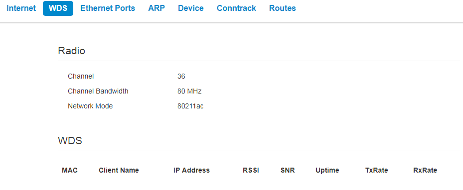
Radio:
- Channel – a channel of wireless bridge;
- Channel Bandwidth – channel bandwidth used for wireless bridge;
- Network mode – the current network mode of the radiointerface.
WDS:
- MAC address – MAC address of the opposite device;
- Client Name – network name of the opposite device;
- IP address – IP address of the opposite device;
- Link Capacity – parameter that reflects the effectiveness of the use of a modulation by the device on the transmission. It is calculated based on the number of packets transmitted on each modulation, and the reduction factors. The maximum value is 100% (means that all packets are transmitted at maximum modulation for the maximum nss type supported by the device). The minimum value is 2% (in the case when the packets are transmitted to the modulation nss1mcs0 for the device with MIMO 3x3 support). The parameter value is calculated for the last 10 s;
- Link Quality – parameter that displays the status of the link, calculated based on the number of sent retransmit packets. The maximum value is 100% (all transmitted packets were sent on the first attempt), the minimum value is 0% (no packets were successfully sent). The parameter value is calculated for the last 10 s;
- Link Quality Common – parameter that displays the status of the link, calculated based on the number of sent retransmit packets. The maximum value is 100% (all transmitted packets were sent on the first attempt), the minimum value is 0% (no packets were successfully sent). The parameter value is calculated for the entireconnection time;
- RSSI – level of signal received from the opposite device, dBm;
- SNR – signal/noise ratio, dB;
- Uptime – time of wireless bridge operation;
- TxRate – channel data rate of transmission, Mbps;
- RxRate – channel data rate of receiving, Mbps.
The 'Ethernet Ports' submenu
You can view Ethernet ports' state in the Ethernet Ports submenu.
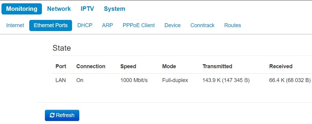
State
- Port – a port name:
- LAN – a local network port.
- Connection – port connection state:
- On – network device is connected to the port (connection is active);
- Off – network device is not connected to the port (connection is inactive).
- Speed – speed of external network device connection to the port (10/100/1000 Mbps);
- Mode – data transmission mode:
- Full-duplex – full-duplex mode;
- Half-duplex – half-duplex mode;
- Transmitted – the quantity of bytes transmitted from the port;
- Received – the quantity of bytes received by the port.
To obtain current information on Ethernet ports states, click the 'Refresh' button.
The 'DHCP' submenu
The list of network devices connected to LAN interface of the device, whose IP addresses were assigned by local DHCP server, is given in the DHCP submenu. The expire time of address lease is shown in the table as well.
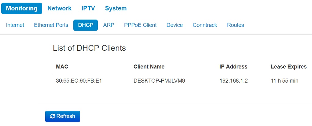
List of DHCP Clients
- MAC – MAC address of connected device;
- Client name – network name of connected device;
- IP address – IP address assigned from adresses pool;
- Lease Expires – time range after which the lease of the address expires.
To obtain current information on DHCP clients, click the 'Refresh' button.
The 'ARP' submenu
You can view ARP table in ARP submenu. ARP table contain information on IP and MAC addresses mapping.
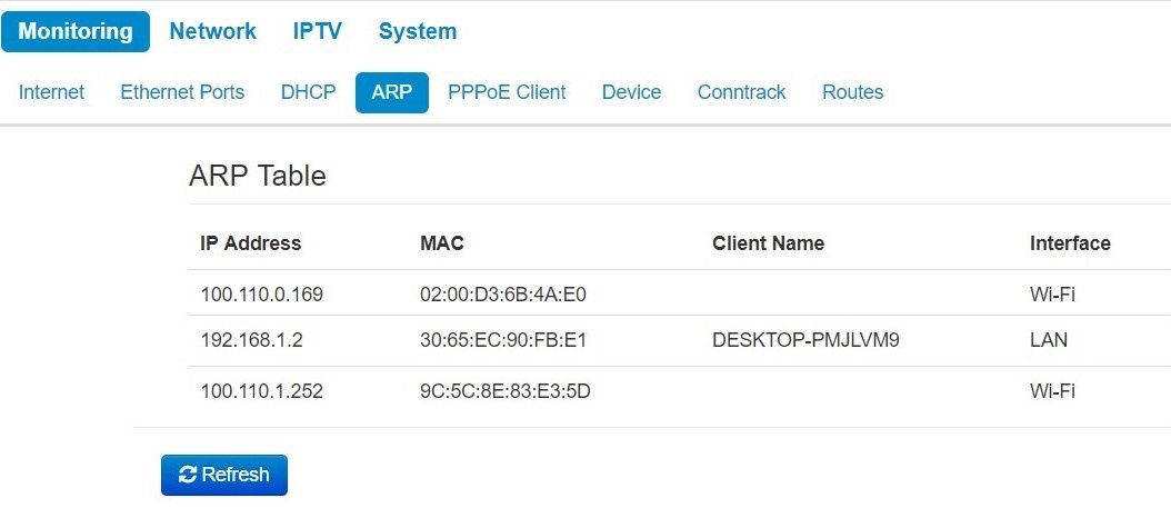
ARP Table
- IP address – device IP address;
- MAC – device MAC address;
- Client name – device hostname (if there is one);
- Interface – interface of the device active side: LAN, Wi-Fi or Bridge.
To get current information, click the 'Refresh' button.
The 'PPPoE Relay' submenu
The 'PPPoE Relay' submenu is only available in the 'Wi-Fi Client' device mode in the 'Bridge' operation mode.
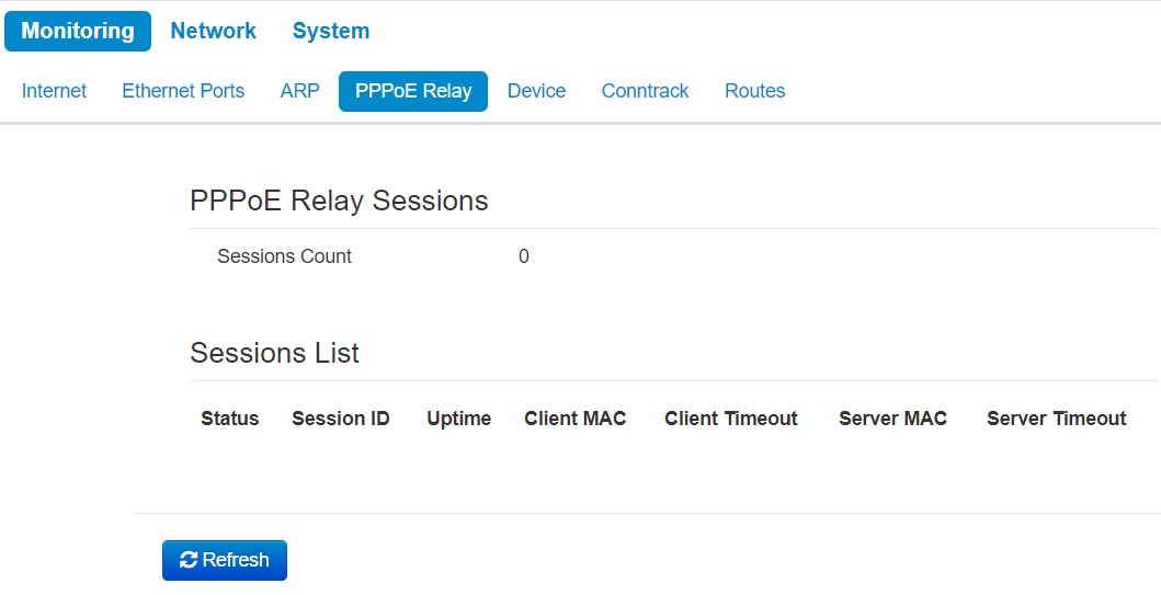
- Sessions Count – the quantity of PPPoE sessions established through the device. The maximum value – 64.
- Status – active or inactive session.
- Session ID – number of session.
- Uptime – session uptime.
- Client Timeout – time since the last packet from the client is received;
- Server Timeout – time since the last packet from the server is received.
You can also see information about the MAC address of the client and server.
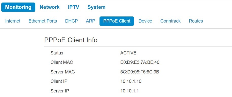
The ' PPPoE Client ' submenu
The 'PPPoE Client' submenu is available only in the 'Router' mode
On the page you can see information about the MAC address and the IP address of the client and server. The 'Status' parameter displays the session state - whether session is active or inactive.
The 'Device Info' submenu
General information on the device is given in the Device Info submenu.
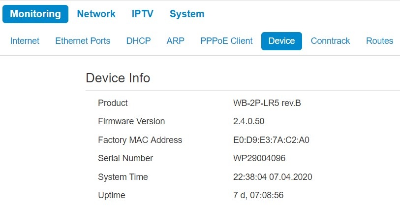
Device info
- Product - device model name;
- Firmware Version – device firmware version;
- Factory MAC Address – MAC address of the device's WAN interface, defined by the manufacturer;
- Serial number – device serial number defined by the manufacture;
- System time – current time and date set in the system;
- Uptime – time of operation since the last startup or reboot of the device.
The 'Conntrack' submenu
In the 'Conntrack' submenu you can find the current active network connections of the device.
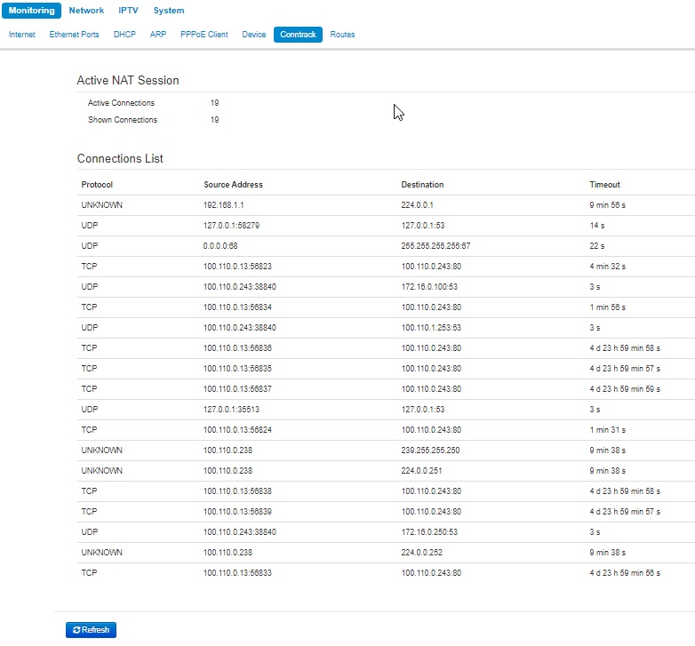
Active NAT Session
- Active Connections – total number of active network connections;
- Shown Connections – number of connections shown in the web interface. In order to maintain high performance of the web interface, the maximum number of connections shown is limited to 1024. You can view other connections through the device console.
Connections List
- Protocol – protocol through which the connection has been established;
- Source Address – IP address and port number of the connection initiator;
- Destination – destination IP address and port number;
- Timeout – time period until the connection termination.
To get current information, click the 'Refresh' button.
The 'Routes' submenu
In the 'Routes' submenu you can view the device route table.
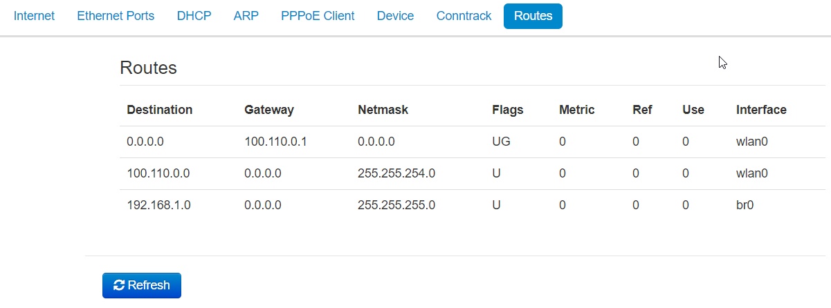
- Destination – IP address of destination host or subnet that the route is established to;
- Gateway – IP address of the gateway, through which access to the addressee is implemented;
- Netmask – subnet mask;
- Flags – specific route attributes. The following flag values exist:
- U – means that the route is created and passable;
- H – identifies the route to the specific host;
- G – means that the route lies through the external gateway; System network interface provides routes in the network with direct connection. All other routes lie through the external gateways. G flag is used for all routes except for the routes in the direct connection networks.
- R – means that the route most likely was created by a dynamic routing protocol running on a local system through the 'reinstate' parameter;
- D – means that the route was added on reception of the ICMP Redirect Message. When the system learns the route from the ICMP Redirect message, the route will be added into the routing table in order to exclude redirection of the following packets intended for the same destination.
- M – means that the route was modified – likely by a dynamic routing protocol running on a local system with the 'mod' parameter applied;
- A – means buffered route with corresponding record in the ARP table;
- С – means that the route source is the core routing buffer;
- L – means that the route destination is an address of this PC. Such 'local routes' exist in the routing buffer only.
- В – means that the route destination is a broadcasting address. Such 'broadcast routes' exist in the routing buffer only.
- I – means that the route is related to the loopback interface and not to address to a ring network. Such 'internal routes' exist in the routing buffer only.
- ! – means that datagrams sent to this address will be rejected by the system.
- Metric – defines route cost. Metrics allows you to sort the duplicate routes, if they are exist in the table.
- Ref – identified number of references to the route for connection establishment (not used by the system).
- Use – number of route detections performed by IP protocol.
- Interface – name of the network interface that the route lies through.
To get current information, click the 'Refresh' button.
The 'Network' menu
You can implement main network settings in the 'Network' menu.
The 'Internet' submenu
In 'Internet' submenu, you can configure parameters to connect to a base station via Wi-Fi and select connection mode.
Wi-Fi client mode
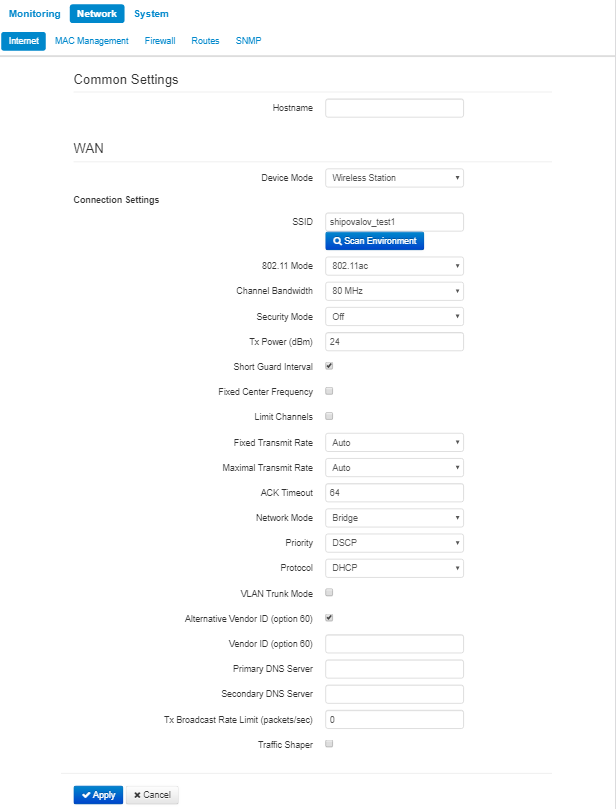
- Hostname – a name of the network device;
- Device mode – a mode of device connection;
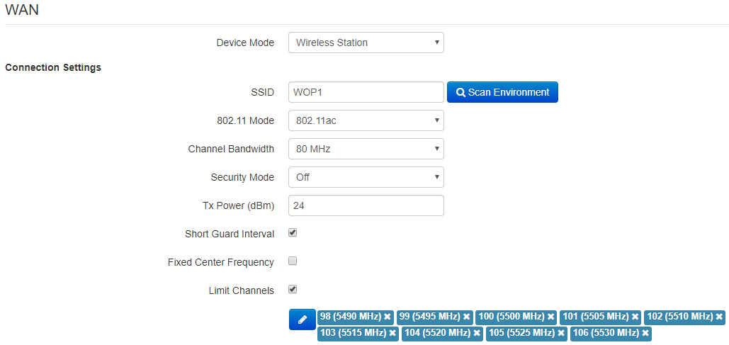
- SSID – wireless network ID, which is used for base station connection. The maximum name lenght – 32 symbols, the keyboard register is important. The name can consist of digits, Latin letters and symbols '-', '_', '.', '!', ';', '#' and space, although it is forbidden to start with the symbols '!', ';', '#' and space.
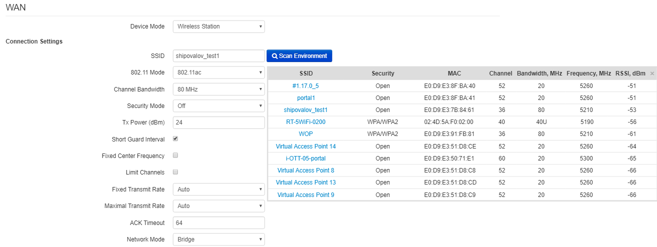
- Scan Environment – click the button to start scanning at the defined range. The list of found access points will be displayed. The list of access points consists of seven columns: access point SSID, security mode, MAC address, channel, channel bandwidth, frequency, signal level. If you select any access point from the list, SSID field will be filled automatically, and the corresponding mode will be selected.
- 802.11 Mode – select wireless interface operation mode:
- 802.11a – the standard supposes maximum rate of up to 54 Mbps;
- 802.11n – the standard supposes maximum rate of up to 300 Mbps;
- 802.11ac – the standard supposes maximum rate of up to 866.7 Mbps.
- Channel Bandwidth – channel bandwidth, on which a Wi-Fi client operates. The parameter can take values from 5, 10, 20, 40 and 80 MHz. Note, that channel bandwidth of 80 MHz will operate only according to 802.11ac standard. If the base station has 5 or 10 MHz bandwidth, you should select the same bandwidth on the user station.
- Security mode – select security mode for wireless network:
- Off – encryption of the wireless network is off, low security.
- WEP – WEP authentication. WEP-key should consist of hexadecimal digits and be of 10 or 26 symbols lenght or it might be a string (a-z, A-Z, 0-9, ~!@#$%^&*()_-+= symbols) with length of 5 or 13 symbols. The mode is hidden in the web interface.
- WPA, WPA2 – WPA and WPA2 authentication. The key length is from 8 to 63 symbols. Only the following characters can be used: a-z, A-Z, 0-9, ~!@#$%^&*()_-+=;:
|/?.,<>"`' or space. It is recommended to use WPA and WPA2 encryption modes as the safetest. - WPA-Enterprise, WPA2-Enterprise – WPA and WPA2 encryption with client authentication via 802.1x. Enter username and password as authentication data.
- Tx Power (dBm) – transmitting Wi-Fi signal power adjustment, dBm.
- Short Guard Interval – support for shortened guard interval. 400 ns interval is used (instead of 800 ns).
- Fixed center frequency – when the flag is checked, all traffic (data and management packets) will be transmitted on the specified center channel frequency with a given bandwidth (40 or 80 MHz). The function is proprietary, the transmission is not carried out according to IEEE 802.11 standards, where it is supposed to use different center frequencies for data and management traffic with 40/80 MHz bandwidth. When using the WB-2P-LR5 with WOP-2ac-LR5 devices with enabled fixed center frequency, activation at the subscriber station is not required, because happens automatically at the moment of connection to the base station.
- Limit Channels – the list of frequencies on which the air is scanned to connect to the base station.
For example, if a channel 100L (5490-5530) with a 40 MHz band is set on the BS, then in the list of allowed channels should be selected all the channels in this frequency range: 98 - 106 channel inclusive. With this setting, the WB-2P-LR5 will only scan the frequency range of 5,490 - 5,530 MHz and successfully connect to the BS on the 100L/40 channel;
- Fixed Transmit Rate – fixed wireless data transmission rate which is defined by IEEE 802.11a/n/ac standards;
- Maximum Transmit Rate – maximum allowed wireless data transmission rate which is defined by IEEE 802.11a/n/ac standards;
- ACK Timeout – packet confirmation waiting timeout. When the distance is long (more than 2.5 km), the parameter is recommended to be increased choosing the optimal value;
- Network Mode– device operation mode:
- Router – router mode between LAN and WAN interfaces (WAN interface is the wireless Wi-Fi interface, LAN is isolated from WAN);
- Bridge – bridge mode between wired and wireless interfaces of the device.
- Priority – select prioritization means. Defines a field based on which traffic transmitted to the radio interface will be distributed among WMM queues:
- DSCP – enables analization of priority from the DSCP field of IP packet header;
- 802.1p – enables analization of priority from the CoS (Class of Service) field of tagged packets.
Protocol – select protocol for connection of the device via Wi-Fi interface to service provider network:
- Static – operation mode where IP address and all the necessary parameters for WAN interface are assigned statically. If 'Static' is selected, the following parameters will be available to set:
- WAN IP – set IP address of WAN interface of the device in service provider network;
- Netmask – set subnet mask of device's WAN interface in service provider network;
- Default Gateway – address, to which a packet will be transmitted in case the route has not been found in the route table;
- DHCP – operation mode, when IP address, subnet mask, DNS server address, defualt gateway and other parameters required for operation are obtained from DHCP server automatically. Before obtaining the parameters via DHCP, the access to the device is implemented via address set in IP address field.
- Alternative Vendor ID (Option 60) – when selected, the device transmits Vendor ID (Option 60) field value in Option 60 DHCP messages (Vendor class ID). If the field is empty, Option 60 will not be transmitted in DHCP messages.
If the parameter Alternative Vendor ID (Option 60) is not checked, the defualt value will be transmitted in option 60. The default value has the following format:
[VENDOR:device vendor][DEVICE:device type][HW:hardware version] [SN:serial number][WAN:WAN interface MAC address][LAN:LAN interface MAC address][VERSION:firmware version]
Example:
[VENDOR:Eltex][DEVICE:WB-2P-LR5][HW:1.2][SN:WP29000038] [WAN:E0:D9:E3:75:55:60] [LAN:E0:D9:E3:75:55:60][VERSION:2.0.0.161]
- Alternative Vendor ID (Option 60) – when selected, the device transmits Vendor ID (Option 60) field value in Option 60 DHCP messages (Vendor class ID). If the field is empty, Option 60 will not be transmitted in DHCP messages.
- Static – operation mode where IP address and all the necessary parameters for WAN interface are assigned statically. If 'Static' is selected, the following parameters will be available to set:
- PPPoE (available in router mode) – operation mode when PPP session is established on WAN interface. When PPPoE is selected, the following parameters will be available for editing:
- Username – user name for authorization on PPP server;
- Password – password for authorization on PPP server;
- MTU – the maximum packet size that can be transmitted through a PPP session without fragmentation;
- Service-Name – service provider name. Service-Name tag value in PADI message for PPPoE connection (this parameter is optional, and configured only on the provider's request);
- Secondary access – defines the way to set the IP address on the interface for accessing the device if the management VLAN is not used.
- DHCP – operation mode, when IP address, subnet mask, DNS server address, defualt gateway and other parameters required for operation are obtained from DHCP server automatically;
- Static – operation mode, when IP address and other necessary parameters of WAN interface are set statically (manually). If 'Static' is selected, the following parameters will be available to set:
- WAN IP – set IP address of WAN interface of the device in service provider network;
- Netmask – set subnet mask of device's WAN interface in service provider network;
- Default Gateway – address, to which a packet will be transmitted in case the route has not been found in the route table;
- Primary DNS, Secondary DNS – IP address of DNS servers.
- Disable sender address translation (available in router mode) – the option allows you to disable sender address broadcasting (masquerade);
- Tx Broadcast Rate Limit (packets/sec) – limits transmission to external Wi-Fi network;
- Traffic Shaper – rate limit of both Downlink and Uplink directions. The maximum limit is 200 Mbps.
VLAN trunk in bridge mode
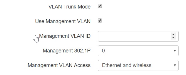
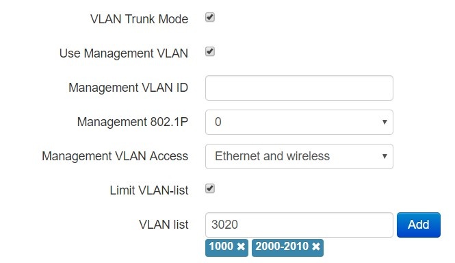
- VLAN Trunk Mode – if checked, the trunk port is activated. The device will transparently transmit all VLANs (including 'Limit VLAN list' option) received from the base station to wired clients and vice versa. At the same time, the passage of untagged traffic depends on the "Transparent mode" option;
- Use Management VLAN – when checked, management VLAN used for access to the device is enabled:
- Management VLAN ID – VLAN identifier, which is used to access the device;
- Management 802.1P – 802.1P attribute (also called CoS – Class of Service), which is attached to egress packets transmitted from this interface. The value is from 0 (the least priority) to 7 (the highest priority);
- Management VLAN Access – restrict access to the management network. Possible values:
- Ethernet and wireless – access to the management network is possible from the wireless and Ethernet interfaces;
- Wireless – access to the management network is only possible from the wireless interface side.
- Use Management VLAN – when checked, management VLAN used for access to the device is enabled:
If the “Use Management VLAN” flag is checked and the Management VLAN is configured incorrectly, access to the device can be lost. When connected via Ethernet, the device will be available at 192.0.3.1.

- Limit VLAN-list – when checked, the device in VLAN trunk mode will pass only a limited number of VLANs, which are specified in the "VLAN list" field.
- VLAN list – contains VLAN identifiers that are allowed for transmission. Accepts values from 1 to 4094, it is possible to specify a range, for example "2000-2010".
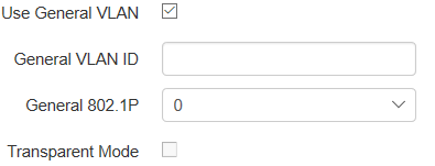
- Use General VLAN – when checked, one VLAN specified in the General VLAN ID field will be removed and the traffic of this VLAN will go to the client without a tag. When traffic flows in the opposite direction, untagged traffic will be tagged with General VLAN ID:
- General VLAN ID – VLAN identifier;
- General 802.1P – 802.1P attribute (also called CoS – Class of Service), which is attached to egress packets transmitted from this interface. The value is from 0 (the least priority) to 7 (the highest priority).
Transparent mode – when checked, the device will pass untagged traffic in the VLAN trunk mode.
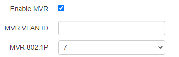
- Enable MVR – when checked, Multicast VLAN Registration is enabled. The function allows you to use a separate VLAN for multicast traffic. In this case the traffic to the subscriber is transmitted without a tag. The parameter is available for configuration if "Use General VLAN" or "Transparent mode" is enabled:
- MVR VLAN ID – ID of the VLAN in which the multicast traffic is transmitted;
- MVR 802.1P – 802.1P attribute (also called CoS – Class of Service), that is set on packets originating on this interface. can take values from 0 (lowest priority) to 7 (highest priority). Default – 7.
VLAN trunk in router mode
- VLAN Trunk Mode – if checked, the trunk port is activated. There is an opportunity to use Management VLAN and Internet VLAN:
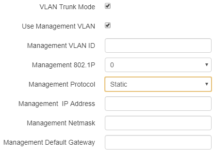
- Use Management VLAN – when checked, management VLAN used for access to the device is enabled:
- Management VLAN ID – VLAN identifier, which is used to access the device;
- Management 802.1P – 802.1P attribute (also called CoS – Class of Service), which is attached to egress IP packets transmitted from this interface. The value is from 0 (the least priority) to 7 (the highest priority).
- Management Protocol – defines management interface operation mode:
- DHCP – operation mode, when IP address, subnet mask, DNS server address, defualt gateway and other parameters required for operation are obtained from DHCP server automatically.
- Static – operation mode where IP address and all the necessary parameters for interface are assigned statically. If 'Static' is selected, the following parameters will be available to set:
- Management IP – set IP address of interface of the device in service provider network;
- Management netmask – set subnet mask of device's interface in service provider network;
- Management Default Gateway – address, to which a packet will be transmitted in case the route has not been found in the route table;
If the “Use Management VLAN” flag is checked and the Management VLAN is configured incorrectly, access to the device can be lost. When connected via Ethernet, the device will be available at 192.0.3.1.
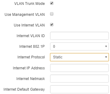
- Use Internet VLAN – when checked, VLAN is enabled to transmit user traffic.
- Internet VLAN ID – VLAN identifier;
- Internet 802.1P – 802.1P attribute (also called CoS – Class of Service), which is attached to egress packets transmitted from this interface. The value is from 0 (the least priority) to 7 (the highest priority
- Internet Protocol – select operation mode of the device interface, used to to transmit user traffic in a separate VLAN.
- DHCP– operation mode, when IP address, subnet mask, DNS server address, defualt gateway and other parameters required for operation are obtained from DHCP server automatically.
- Static – operation mode where IP address and all the necessary parameters for WAN interface are assigned statically. If 'Static' is selected, the following parameters will be available to set:
- Internet IP – set IP address of WAN interface of the device in service provider network;
- Internet Netmask – set subnet mask of device's WAN interface in service provider network;
- Internet Default Gateway – address, to which a packet will be transmitted in case the route has not been found in the route table.
If PPPoE is selected as the Internet protocol, then you can specify the secondary access settings:
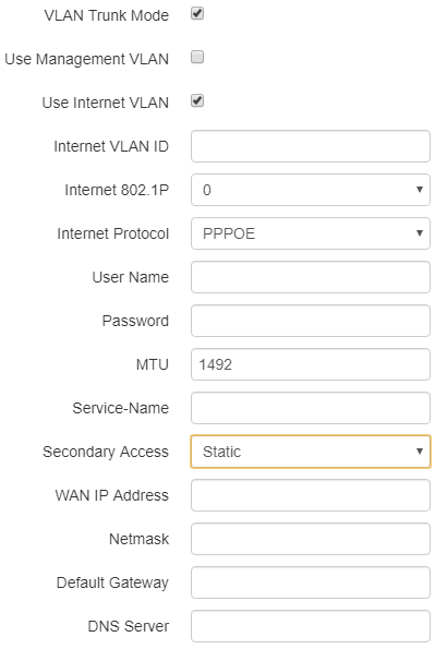
- Secondary access – defines the method of setting the IP address on the interface for accessing the device if the management VLAN is not used.
- DHCP – operation mode, when IP address, subnet mask, DNS server address, defualt gateway and other parameters required for operation are obtained from DHCP server automatically.
- Static – operation mode, when IP address and other necessary parameters of WAN interface are set statically (manually). If 'Static' is selected, the following parameters will be available to set:
- WAN IP – set IP address of WAN interface of the device in service provider network;
- Netmask – set subnet mask of device's WAN interface in service provider network;
- Default Gateway – address, to which a packet will be transmitted in case the route has not been found in the route table;
- DNS server – domain name server address (allows identifying the IP address of the device by its domain name).
VLAN – virtual local area network. VLAN consists of a group of hosts combined into a single network regardless of their location. The devices grouped to a VLAN have the same VLAN-ID identifier.
Wireless bridge mode
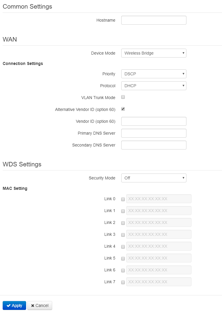
WAN
- Hostname – a name of the network device;
- Device mode – a mode of device connection;
- Priority – select prioritization means. Defines a field based on which traffic transmitted to the radio interface will be distributed among WMM queues:
- DSCP – enables analization of priority from the DSCP field of IP packet header;
- 802.1p – enables analization of priority from the CoS (Class of Service) field of tagged packets.
- Protocol – defines operation mode of the interface through which the connection of the device to service provider network will be performed:
- Static – operation mode where IP address and all the necessary parameters for WAN interface are assigned statically. If 'Static' is selected, the following parameters will be available to set:
- WAN IP – set IP address of WAN interface of the device in service provider network;
- Netmask – set subnet mask of device's WAN interface in service provider network;
- Default Gateway – address, to which a packet will be transmitted in case the route has not been found in the route table;
- DHCP – operation mode, when IP address, subnet mask, DNS server address, default gateway and other parameters required for operation are obtained from DHCP server automatically. Before obtaining the parameters via DHCP, the access to the device is implemented via address set in IP address field.
- Alternative VendorID (Option 60) – when selected, the device transmits VendorID (Option 60) in Option 60 DHCP messages (Vendor class ID). If the field is empty, Option 60 will not be transmitted in DHCP messages.
If the parameter Alternative Vendor ID (Option 60) is not checked, the defualt value will be transmitted in option 60. The default value has the following format:
[VENDOR:device vendor][DEVICE:device type][HW:hardware version] [SN:serial number][WAN:WAN interface MAC address][LAN:LAN interface MAC address][VERSION:firmware version]
Example:
[VENDOR:Eltex][DEVICE:WB-2P-LR5][HW:1.2][SN:WP29000038] [WAN:E0:D9:E3:75:55:60] [LAN:E0:D9:E3:75:55:60][VERSION:2.0.0.161]
- Alternative VendorID (Option 60) – when selected, the device transmits VendorID (Option 60) in Option 60 DHCP messages (Vendor class ID). If the field is empty, Option 60 will not be transmitted in DHCP messages.
- Static – operation mode where IP address and all the necessary parameters for WAN interface are assigned statically. If 'Static' is selected, the following parameters will be available to set:
- Primary DNS, Secondary DNS – IP address of DNS servers;
- VLAN Trunk – if checked, the trunk port is activated. There is an opportunity to use Management VLAN:
- Use Management VLAN – when checked, VLAN used for access to the device is enabled:
- Management VLAN ID – VLAN identifier, which is used to access the device;
- Management 802.1P – 802.1P attribute (also called CoS – Class of Service), which is attached to egress packets transmitted from this interface. The value is from 0 (the least priority) to 7 (the highest priority).
- Management VLAN Access – restrict access to the management network. Possible values:
- Ethernet and wireless – access to the management network is possible from the wireless and Ethernet interfaces;
- Wireless – access to the management network is only possible from the wireless interface side.
- Limit VLAN-list – when checked, the device in VLAN trunk mode will pass only a limited number of VLANs, which are specified in the "VLAN list" field.
- VLAN list – contains VLAN identifiers that are allowed for transmission. Accepts values from 1 to 4094, it is possible to specify a range, for example "2000-2010".
- Use Management VLAN – when checked, VLAN used for access to the device is enabled:
WDS Settings
- Security mode – select security mode for wireless bridge:
- Off – wireless network encryption is off, low security;
- WPA2 – WPA2 authentication. The length of the key makes from 8 to 11 characters. Only the following characters can be used: a-z, A-Z, 0-9, ~!@#$%^&*()_-+=;:
|/?.,<>"`' or space.
- Link X (where X=0..7) – wireless links enabling. Enter MAC address of the device, to which you want to configure the wireless bridge, to a corresponding field next to the Link checkbox.
The 'Radio' submenu
'Radio' submenu is available only in 'Wireless bridge' mode.
In the 'Radio' submenu, you can configure the radiointerface to organize wireless bridge.
Basic settings:
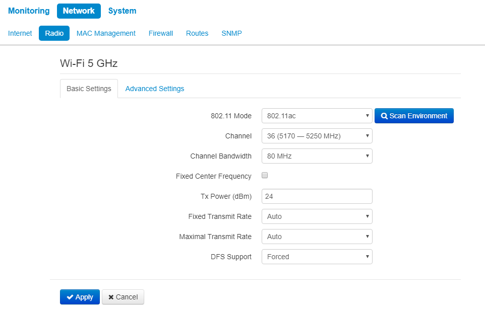
- Scan Environment – click the button to start scanning at the defined range. The list of found access points will be displayed. The list of access points consists of seven coloumns: access point SSID, security mode, MAC address, channel, channel bandwidth, frequency, signal level.
- 802.11 Mode – select wireless interface operation mode:
- 802.11a – the standard supposes maximum rate of up to 54 Mbps;
- 802.11n – the standard supposes maximum rate of up to 300 Mbps;
- 802.11ac – the standard supposes maximum rate of up to 866.7 Mbps.
- Channel – select channel for data transmission;
- Channel Bandwidth – channel bandwidth, on which the radiointerface operates. The parameter can take values from 5, 10, 20, 40 and 80 MHz according to selected mode;
- Fixed center frequency – when the flag is checked, all traffic (data and management packets) will be transmitted on the specified center channel frequency with a given bandwidth (40 or 80 MHz). The function is proprietary, the transmission is not carried out according to IEEE 802.11 standards, where it is supposed to use different center frequencies for data and management traffic with 40/80 MHz bandwidth;
- Tx Power (dBm) – transmitting Wi-Fi signal power adjustment, dBm;
- Fixed Transmit Rate – fixed wireless data transmission rate which is defined by IEEE 802.11a/n/ac standards;
- Maximum Transmit Rate – maximum allowed wireless data transmission rate which is defined by IEEE 802.11a/n/ac standards;
- DFS Support – dynamic frequency selection mechanism. The mechanism demands wireless devices to scan environment and avoid using channels which coincide with radiolocation system's channels at 5 GHz:
- Disabled – the mechanism is disabled. DFS channels are not available for selection;
- Enabled – enable the mechanism;
- Forced – the mechanism is disabled. DFS channels are available for selection.
Advanced settings:
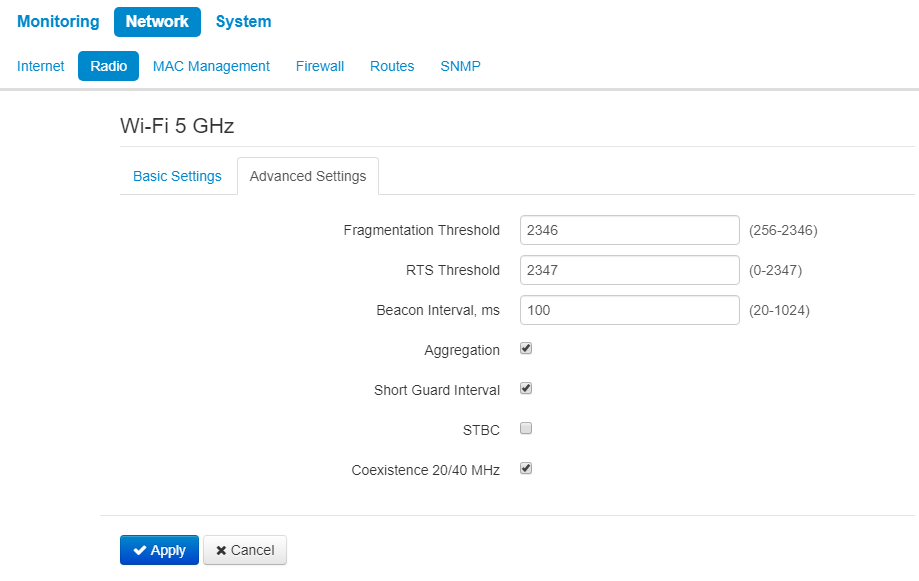
- Fragmentation Threshold – frame fragmentation threshold, bytes. The parameter takes values 256-2346, by default – 2346.
- RTS Threshold – after what quantity of bytes the Request to Send will be sent. Decreasing of the parameter's value might improve access point operation when there are a lot of clients connected. However, decreasing of the parameter's value will reduce general bandwidth of wireless network. The parameter takes values from 0 to 2347, by default – 2347.
- Beacon Interval, ms – beacon frames transmission period. The frames are sent to detect access points. The parameter takes values from 20 to 2000 ms, by default – 100 ms.
- Aggregation – enable support for AMPDU/AMSDU.
- Short Guard interval – support for shortened guard interval. 400 ns interval is used (instead of 800 ns).
- STBC – Soace-Time Block Coding method dedicated to improve data transmission reliability. When checked, the device transmits one data flow through several antennas. When unchecked, the device does not transmit one data flow through several antennas.
- Coexistence 20/40 MHz – automatic bandwidth changing when environment is loaded.
For wireless bridge operation, radiointerface parameters should be configured identically on all the devices.
The 'LAN' submenu
LAN settings are available only in router mode.
In LAN settings section you can configure local network, DHCP server, set static addresses bindings.
The device is capable to assign IP addresses and other parameters required to the Internet access to computers connected to LAN interface through DHCP (Dynamic Host Configuration Protocol). The use of DHCP allows to avoid manual configuration of TCP/IP.
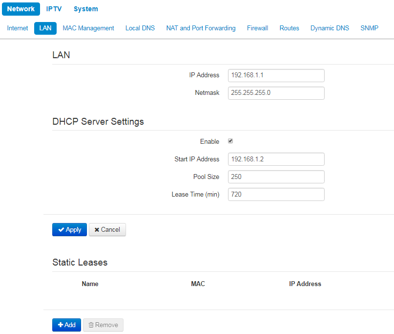
LAN:
- IP address – IP address of the device in a local network;
- Netmask – subnetmask in local network.
DHCP server settings:
- Enable – when cheked, a local DHCP server is enabled, otherwise the server is disabled;
- Start IP address – the initiate address of the IP addresses pool;
- Pool size – the number of addresses in the pool;
- Lease time (min) –set the maximum time range for using an IP address assigned by DHCP server, lease time is set in minutes.
To apply a new configuration and store settings into the non-volatile memory, click the 'Apply' button. To discard changes click the 'Cancel' button.
Static leases
To add a new static binding, click the 'Add' button and fill in the following fields:
- Name – lease name
- MAC address – specify a static MAC address. It is assigned in XX:XX:XX:XX:XX:XX format;
- IP-address – set static IP address for the specified MAC address.
Configuring of static leases is helpful when you need that the certain computer always obtains certain IP address.
Click 'Apply' to add IP address to the list of static IP addresses for DHCP server. To discard changes click the 'Cancel' button.
To delete an address from the list, select the corresponding checkbox and click 'Remove'.
The 'MAC address Management' submenu
In the MAC address Management submenu, you can set MAC address of the device's WAN interface.
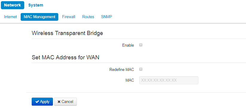
Wireless transparent bridge
'Wireless transparent bridge' settings are available for Bridge mode of Wi-Fi station only.
When you enable Wireless transparent bridge, WB-2P-LR5 will not substitute client MAC addresses from LAN with own MAC address. The limit is 15 MAC addresses without substitution. When the value is exceeded client's MAC address will be substituted. The section of connected clients on a base station will include MAC addresses of client devices from LAN.
Set MAC address for WAN
- Redefine MAC – when checked, the MAC address from the field MAC is used.
To apply a new configuration and save setting to non-volatile memory, click 'Apply'. Click 'Cancel' to discard the changes.
The 'Local DNS' submenu
"Local DNS" submenu is available only in router mode.
You can configure local DNS server of the device by adding IP address and domain name in the "Local DNS" submenu.
Local DNS allows to obtain an IP address of the device using its domain name (host) in case of lack of DNS server in a network segment. To implemet this, you should know concordances between nodes names (hosts) and their IP addresses.
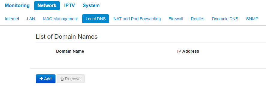
Nodes configuration
To add the address into the list, click 'Add' button in the 'New domain name' window and fill in the following fields:
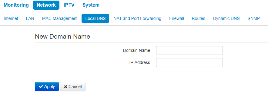
- Domain name – host name;
- IP Address – node's IP address.
Click Apply to create 'IP address – domain name' pair. To discard changes click the 'Cancel' button. To delete the record from the list, select the checkbox next to the respective record and click 'Delete'.
The 'NAT and Port Forwarding' submenu
NAT and Port Forwarding submenu is available only for router mode.
You can configure Port Forwarding from WAN interface to LAN interface in NAT and Port Forwarding submenu.
NAT (Network Address Translation) mode allows to modify IP addresses and network ports of IP packets. Port forwarding is necessary when TCP/UDP connection with local PC (connected to LAN interface) is established via external network. The settings menu allows to set rules which permit packets transmission from external network to specified address in a local network, i.e. to establish connection. Port forwarding is also necessary when using torrent and p2p services. To implement the configuration, find TCP/UDP ports used by torrent or p2p clients in settings and set them for corresponding port forwarding rules to a PC IP address.
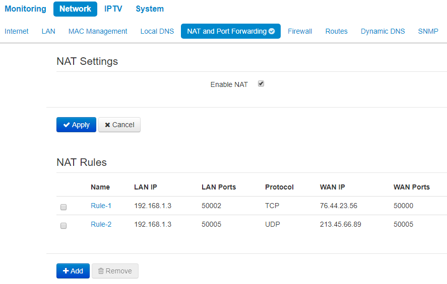
NAT rules
To add a new NAT rule, click 'Add' button and fill in the following fields in the Add a new rule window:
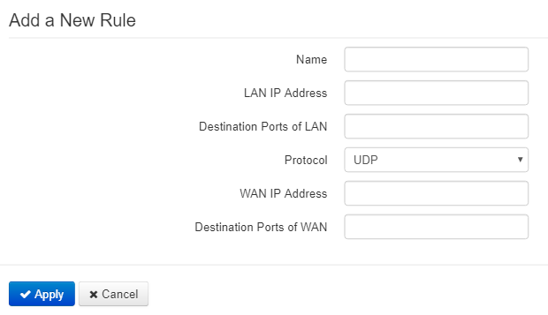
- Name – name of the rule (it is obligitory to fill the field);
- LAN IP Address – IP address of host in local network. Packets translated to this host will follow the rule;
- Destination ports of LAN – receiver TCP/UDP ports, via which packets are translated to local network (you can assign either single port or range of ports using dash);
- Protocol – selection of the packet protocol falling under this rule: TCP, UDP, TCP/UDP;
- WAN IP address – source IP address in external network which will be under the rule;
- Destination Ports of WAN – destination TCP/UDP ports in external network, packets from which will follow the rule (you can assign either single port or range of ports using dash).
Port forwarding rule will work as follows: a packet received via 'Protocol' on a port defined in 'Destination Ports of WAN' field and having source address defined in 'WAN IP address' field (if the field is empty, source IP does not consider) undergoes address and Destination port substitute with the parameters defined in 'LAN IP Address' and 'Destination Ports of LAN' fields respectively.
Click 'Apply' button to add a new rule. To discard changes click 'Cancel' button.
To delete an entry from the list, select corresponding checkbox and click 'Remove'.
The 'Firewall' submenu
In the Firewall submenu, you can set the rules for the incoming, outgoing, and transit traffic transmission. There is an opportunity to limit transmission of different types of traffic (incoming, outgoing, transit) depending on protocol type, source and destination IP, TCP/UDP source and destination ports, type of ICMP message.
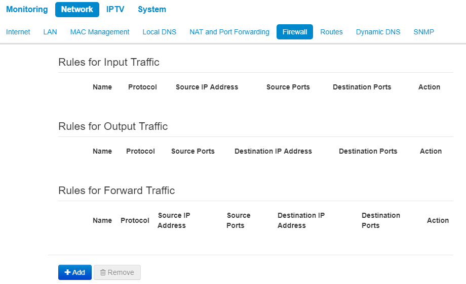
Firewall rules configuration
To add a new NAT rule, click 'Add' button and fill in the following fields in the Add a new rule window:
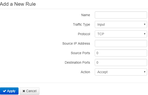
- Name – rule name;
- Traffic Type – select traffic type for which you create the rule:
- Input – incoming traffic (the receiver is one of the network interfaces of the device). If the parameter is selected, the following field will be displayed:
- Source IP address – a source IP address. You can set subnet mask after '/' character. The subnet mask should be set in the following formats: xxx.xxx.xxx.xxx or xx, e.g. 192.168.16.0/24 or 192.168.16.0/255.255.255.0 to set addresses range (the subnet mask entry /24 coincides with /255.255.255.0 entry);
- Output – outgoing traffic (traffic which is generated by the device locally from a network interface). If the parameter is selected, the following field will be displayed:
- Destination IP address – set destination IP address. You can set subnet mask after '/' character. The subnet mask should be set in the following formats: xxx.xxx.xxx.xxx or xx, e.g. 192.168.16.0/24 or 192.168.16.0/255.255.255.0 to set addresses range (the subnet mask entry /24 coincides with /255.255.255.0 entry);
- Input – incoming traffic (the receiver is one of the network interfaces of the device). If the parameter is selected, the following field will be displayed:
- Protocol – a protocol of the packets, which will follow the rule: TCP, UDP, TCP/UDP, ICMP, any;
- Action – an action for packets to undergo (accept/drop).
When TCP, UDP, TCP/UDP protocols are selected, the following settings will be available to configure:
- Source ports – the list of source ports, packets from which will follow the rule (it is acceptable to specify single port or range of ports using the dash sign). To specify all the source ports, enter '0–65535';
- Destination ports – the list of destination ports, packets from which will follow the rule (it is acceptable to specify single port or range of ports using the dash sign). To specify all the source ports, enter '0–65535'.
When ICMP is selected, the following settings will be available for editting:
- Type of ICMP Message – you can create a rule for a certain ICMP messages type or for all types.
Click 'Apply' button to add a new rule. Click 'Cancel' to discard the changes. To delete a created rule, check the box next to the rule and click 'Remove'.
The 'Routes' submenu
You can set static routes in the Routes submenu.
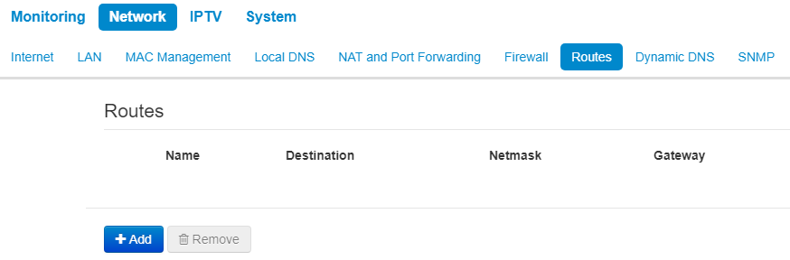
Click 'Add' button to add a new route. Fill the following fields:
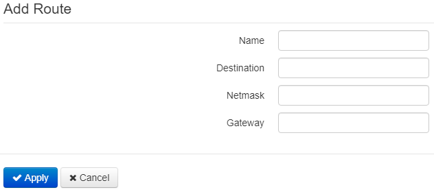
- Name – route name.
- Destination – destination host or subnet IP address, to which the route will be set.
- Netmask – a subnet mask. A subnet mask for a host is set to 255.255.255.255 value, for a subnet — depending on its size.
- Gateway – IP address of the gateway through which the device can access Destination.
To apply a new configuration and store settings into the non-volatile memory, click the 'Apply' button. To discard changes click 'Cancel' button.
The 'Dynamic DNS' submenu
Dynamic DNS submenu is available only in router mode.
In dynamic DNS submenu, you can configure the coresponding service.
- Dynamic DNS (D-DNS) provides information on DNS server update in real time or automatically, if necessary. It is used to assign a permanent domain name to a device (PC, router) with dynamic IP address.
Dynamic DNS is often used in local networks, where clients obtain IP addresses via DHCP, and then register their names on local DNS server.
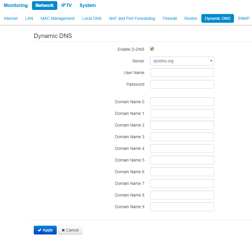
- Enable D-DNS – when checked, D-DNS service is enabled. The following field are available:
- Server – D-DNS provider name – select one of the available providers;
- User Name – a user name for access to D-DNS service account;
- Password – a password for access to D-DNS service account;
- Domain name (0..9) – you can register up to 10 domain names (usually only one is required). The update of data on IP address of the device is implemented once in 60 seconds on a provider server.
To apply a new configuration and store settings into the non-volatile memory, click the 'Apply' button. To discard changes click the 'Cancel' button.
The 'SNMP' submenu
WB-2P-LR5 software allows monitoring of the device status and its sensors via SNMP. In SNMP submenu, you can configure settings of SNMP agent. The device supports SNMPv1, SNMPv2c.
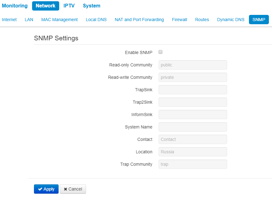
- Enable SNMP – when checked, SNMP will be enabled for utilization;
- Read-only Community – a password to read the parameters (by default: public);
- Read-write Community – a password to configure (write) parameters (by default: private);
- TrapSink – an IP address or domain name of SNMPv1-trap messages receiver in HOST [COMMUNITY [PORT]] format;
- Trap2Sink – an IP address or domain name of SNMPv2-trap messages receiver in HOST [COMMUNITY [PORT]] format;
- InformSink – an IP address or domain name of Inform messages receiver in HOST [COMMUNITY [PORT]] format;
- System Name – device name;
- Contact – the manufacturer contact;
- Location – information on the device location;
- Trap Community – a password which is contained in traps (by default: trap).
The list of objects which are supported for reading and configuration via SNMP is given below:
- eltexLtd.1.164.1 – subscriber station parameters monitoring;
where eltexLtd – 1.3.6.1.4.1.35265 is Eltex Enterprise identifier.
To apply a new configuration and save setting to non-volatile memory, click 'Apply'. Click 'Cancel' to discard the changes.
The 'IPTV' menu
The menu is available only in router mode.
The 'IPTV' submenu
You can configure IPTV service in IPTV settings menu.
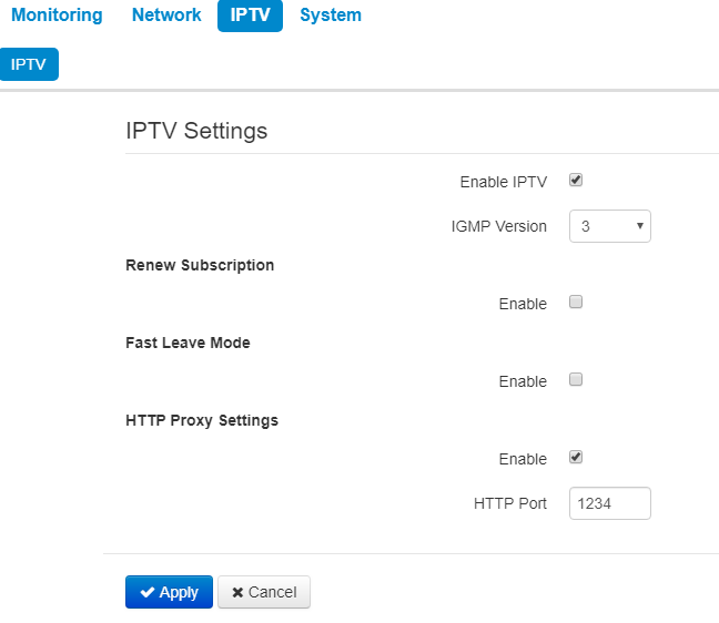
- Enable IPTV – when checked, IPTV signals transmission via WAN interface (from provider network) to the devices connected to the LAN interface is enabled;
- IGMP version – IGMP protocol verion for IGMP messages transmission via WAN interface (messages of activation or deactivation of subscribtion to IPTV channels). Versions 2 and 3 are supported.
Renew subscription
- Enable – when checked, messages with data on the list of active IPTV channels are periodically transmitted to a higher server which implements IPTV signals translation. Enabling of the function is necessary if a higher server disables IPTV channels translation in a certain period of time.
- Renew Subscription Interval, s – a period of messages transmission with data on active IPTV channels list, specified in seconds. Set the value of interval less than interval (timeout) of higher server signals translation disabling.
Fast leave mode
- Enable – when checked, the option for fast exit from the multicast group is enabled. The function is not recommended when more than one multicast traffic receiver is used.
HTTP Proxy Settings
- Enable – when checked, HTTP Proxy function is enabled. HTTP Proxy implements modification of UDP stream to HTTP stream using TCP (transmission control protocol), that allows to improve quality of transmitted image in case of poor communication channel quality in a local network. The function is useful when IPTV is watched via wireless Wi-Fi channel.
- HTTP Port – a number of HTTP Proxy port, from which video stream will be translated. Use this port to connect IPTV streams translated by the device.
For instance, if the device has the 192.168.0.1 address on the LAN interface, Proxy server's value is 1234 and you need to playback 227.50.50.100 channel broadcasted to UDP port 1234, set stream address for VLC programm in the form of: http://@192.168.0.1:1234/udp/227.50.50.100:9000.
To apply a new configuration and store settings into the non-volatile memory, click the 'Apply' button. To discard changes click the 'Cancel' button.
The 'System' menu
In the System menu, you can configure system parameters: time, access via different protocols, change password, upgrade firmware.
The 'Time' submenu
The configuration of time synchronization protocol (NTP) is implemented in the Time submenu.
Time settings
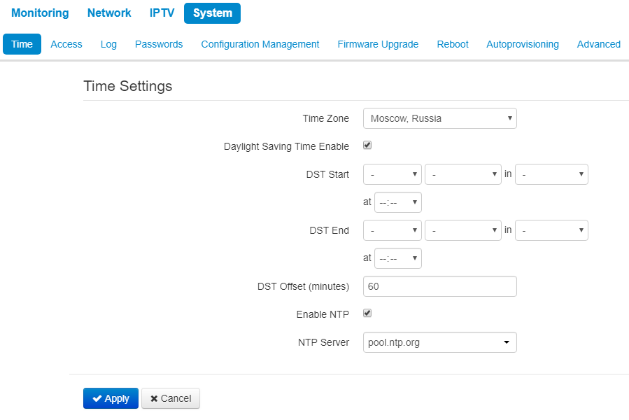
- Time Zone – allows you to set a timezone from the list according to the nearest city in your region;
- Daylight Saving Time Enable – when selected, automatic daylight saving change will be performed automatically within the defined time period:
- DST Start – daylight saving change starting day and time;
- DST End – daylight saving change ending day and time;
- DST Offset (minutes) – time shift in minutes.
- Enable NTP – check to enable device system time synchronization with the particular NTP server;
- NTP Server – time synchronization server IP address/domain name.
To apply a new configuration and store settings into the non-volatile memory, click the 'Apply' button. To discard changes click the 'Cancel' button.
The 'Access' submenu
In the Access submenu, you can configure access to the device via web interface, Telnet and SSH.
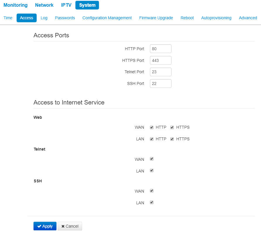
Access ports
In this section you can configure TCP ports for the access to the device via HTTP, HTTPS, Telnet, and SSH.
- HTTP port – number of the port for access to the device web interface via HTTP, default value is 80;
- HTTPS port – number of the port for access to the device web interface via HTTPS (HTTP Secure – secure connection), default value is 443;
- Telnet port – number of the port for access to the device web interface via Telnet, default value is 23;
- SSH Port – number of port for access to web intervace via SSH (default is 22).
You can use Telnet and SSH protocols in order to access the command line (Linux console).
Access to Internet service
This section allows or denies access to the device with separate rules for local and external networks (router mode). For this you need to set the following permissions:
Web:
- HTTP – when checked, connection to the device web configurator through WAN port via HTTP is enabled (insecure connection);
- HTTPS – when checked, connection to the device web configurator through WAN port via HTTP is enabled HTTPS (secure connection).
Telnet:
Telnet – a protocol that allows you to establish mechanisms for remote control of the devices. It allows you to connect to the device via network for configuration and management purposes.
To enable the device access via Telnet protocol, select the corresponding checkbox.
SSH:
SSH – is a secure device remote control protocol. As opposed to Telnet, SSH encrypts all traffic being transferred including passwords.
To enable the device access via SSH protocol, select the corresponding checkbox.
To apply a new configuration and store settings into the non-volatile memory, click the 'Apply' button. To discard changes click the 'Cancel' button.
The 'Log' submenu
In Log submenu you can configure output for various debug messages intended for device troubleshooting. Debug information can be provided by the following device firmware modules:
- Networkd Log – deals with the device configuration according to the configuration file.
- Configd Log – deals with the configuration file operations (config file reads and writes from various sources) and the device monitoring data collection.
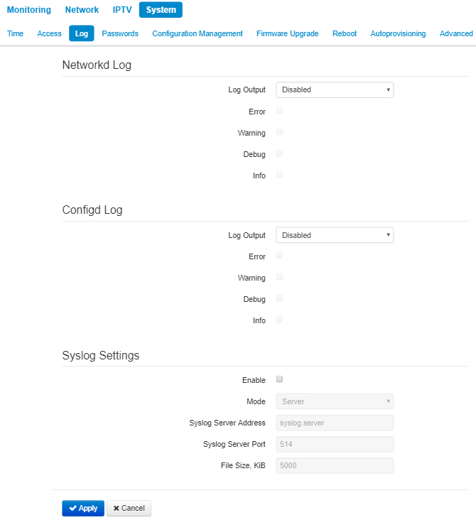
Networkd Log
- Log output – log messages output direction:
- Disabled – the output is disabled;
- Syslog – messages are output to remote server or local file via syslog protocol (for protocol configuration, see below);
- Console – messages are output to the device console (requires connection via COM port adapter);
- Telnet – messages are output to the telnet session; create telnet protocol connection first.
Select types of messages to be output in Networkd Log:
- Error – check to collect 'Error' type messages;
- Warnings – check to collect 'Warning' type messages;
- Debug – check to collect debug messages;
- Info – check to collect information messages;
Configd Log
- Log output – log messages output direction:
- Disabled – the output is disabled;
- Syslog – messages are output to remote server or local file via syslog protocol (for protocol configuration, see below);
- Console – messages are output to the device console (requires connection via COM port adapter);
- Telnet – messages are output to the telnet session; create telnet protocol connection first.
Select types of messages to be output in Configd Log:
- Error – check to collect 'Error' type messages;
- Warnings – check to collect 'Warning' type messages;
- Debug – check to collect debug messages;
- Info – check to collect information messages.
Syslog settings
If there is at least a single log (Networkd Log or Configd Log) configured for Syslog output, you should enable Syslog agent that will intercept debug messages and send them to a remote server or save them to a local file in Syslog format.
- Enable – when selected, user Syslog agent is launched;
- Mode – Syslog agent operation mode:
- Server – log information will be sent to a remote Syslog server;
- Local file – log information will be saved to a local file;
- Server and file – log information will be sent to a remote Syslog server and saved to a local file.
According to Syslog agent mode, the following settings might be avaliable:
- Syslog server address – Syslog server IP address or domain name (required for 'Server', 'Server and file' modes);
- Syslog server port – port for Syslog server incoming messages (default value is 514; required for 'Server', 'Server and file' modes);
- File name – name of the file to store log in Syslog format (required for 'Local file', 'Server and file' modes) Clicking on the 'Show Log' link will open a page with the contents of the Syslog file;
- File size, KB – maximum log file size (required for 'Local file', 'Server and file' modes).
The 'Passwords' submenu
In the 'Passwords' submenu you can define passwords for administrator and viewer access.
The set passwords are used for access to the device via web interface, Telnet and SSH.
When logging in via web interface administrator (default password: password) has the full access to the device: read/write any settings, full device status monitoring. A viewer (password by default: viewer) has rights to view configuration and device monitoring data. Viewer is not permitted to change settings.
Administrator login: admin
Viewer login: viewer
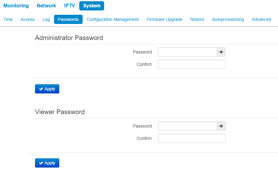
- Administrator password – enter administrator password in the corresponding field and confirm it;
- Viewer password – enter user password in the corresponding field and confirm it.
To apply a new configuration and store settings into the non-volatile memory, click the 'Apply' button. To discard changes click the 'Cancel' button.
The 'Configuration management' submenu
In the 'Configuration management' submenu you can save and update the current configuration.
Backup configuration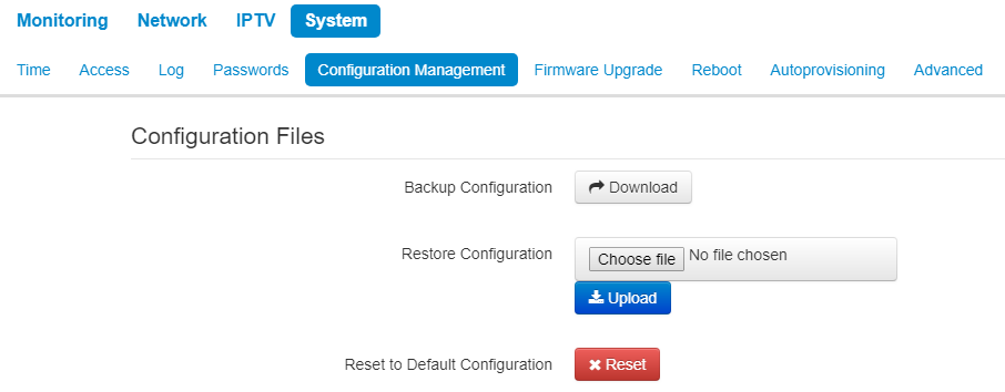
To save the current device configuration to a local PC, click 'Download' button.
Restore Configuration
- Upload configuration archive to the device - upload of configuration file saved on local computer. To update the device configuration click the 'Choose file' button, specify a file (in .tar.gz format) and click the 'Upload' button. Uploaded configuration will be applied automatically and does not require device reboot.
Note that all the passwords of configuration are encrypted with a key depending on device MAC address. Before loading a configuration from one device to another, you should change all passwords in configuration file.
To change the passwords open the configuration file in text editor and change passwords. Then save the changes in configuration archive. The example of password changing is shown below:
   Passwords:
       AdminPassword: "encrypted:7C607178736B7465"
       ViewerPassword: "encrypted:7A68677C6176"
changes to
   Passwords:
       AdminPassword: "password"
       ViewerPassword: "password"
Reset to Default Configuration
To reset all the settings to default values, click 'Reset' button.
The 'Firmware Upgrade' submenu
The Firmware Upgrade submenu is dedicated to update firmware version of the device.
WB-2P-LR5 firmware upgrade:
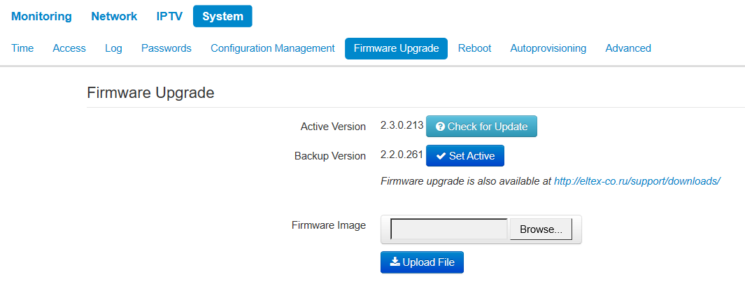
- Active Version of Firmware – installed firmware version, which is operating at the moment;
- Backup version – installed firmware version which can be used in case of problems with the current active firmware version;
- Check for upgrade – click this button to check the availability of the latest firmware version. With this function, you can quickly check the latest firmware version and upgrade the firmware, if necessary;
- Set active – the button which allows you to set a backup file active. The device reboot is required. The active firmware version will not be set as a backup.
Firmware update check function requires access to the Internet.
You can upgrade the device firmware manually by downloading the firmware file from the web site https://eltex-co.ru/support/downloads/ and saving it on the computer. To do this, click the 'Browse' button in the 'Firmware Image' field, and specify path to firmware in the.tar.gz format file.
To start the upgrade process, click the 'Upload file' button. The process can take several minutes (its current status will be shown on the page). The device will be automatically rebooted when the upgrade is completed.
Do not switch off or reboot the device during the firmware upgrade. When you upgrade the device from 2.0.0 to 2.1.0 firmware version, you should reset the device to factory settings and configure it once again according to your requirements, or preliminary set signal power in Network–>Internet submenu as no more than 16 dBm.
The 'Reboot' submenu
In the 'Reboot' submenu you can reboot the device.
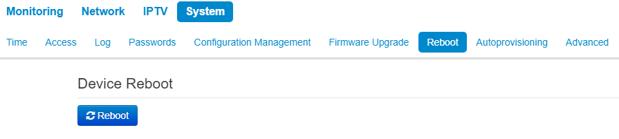
Click the 'Reboot' button to reboot the device. Device reboot process takes approximately 1 minute to complete.
The 'Autoprovisioning' submenu
In the 'Autoprovisioning' submenu you can configure DHCP-based autoprovisioning algorithm and subscriber device automatic configuration protocol TR-069.
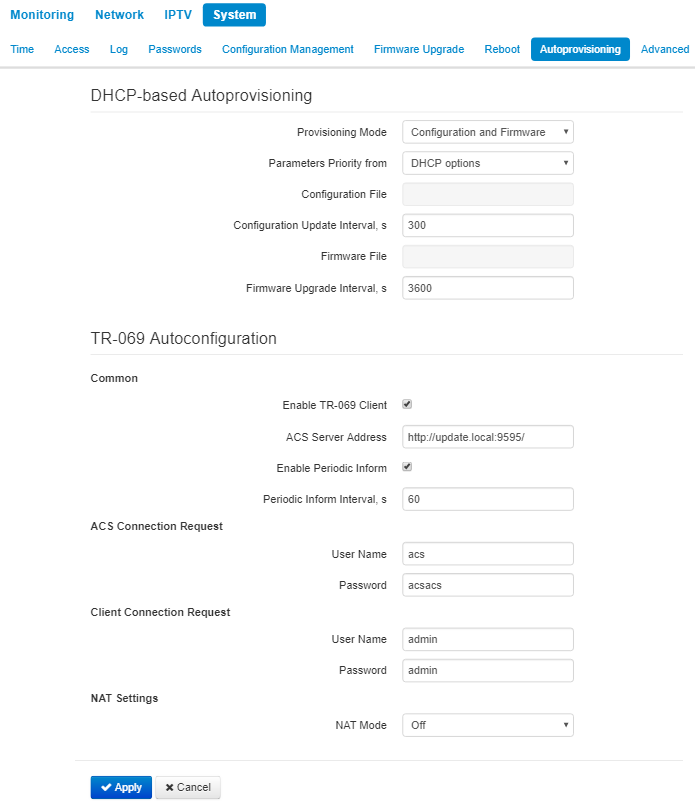
DHCP-based Autoprovisioning:
- Provisioning Mode – select a mode for automatic device update. The followings are available:
- Disabled – automatic update of configuration and firmware is disabled;
- Configuration and Firmware – periodical configuration and firmware update is permitted;
- Configuration only – only periodical update of configuration is permitted;
- Firmware only – only periodical update of firmware is permitted.
- Parameters Priority from – the parameter defines names and locations of configuration and firmware files:
- Static settings – paths to configuration and firmware files are defined by the 'Configuration file'and 'Firmware file' settings correspondingly; more detailed information on the algorithm see in section An algorithm of automatic update based on DHCP;
- DHCP options – paths to configuration and firmware files are defined by the DHCP Option 43, 66, and 67 (to do this, you should select DHCP for the Internet service); more detailed information on the algorithm see in section An algorithm of automatic update based on DHCP;
- Configuration File – full path to configuration file – set in URL format (there is an opportunity to load configuration files via TFTP):
tftp://<server address>/<full path to cfg file>
where < server address > – TFTP server address (domain name or IPv4),
< full path to cfg file > – full path to configuration file on the server;
- Configuration Upgrade interval, s - the time interval in seconds, after which the device configuration is periodically updated. If 0 is set, update of the device will be implemented once, right after reloading of the device;
- Firmware File– full path to firmware file – set in URL format (there is an opportunity to load configuration files via TFTP):
tftp://<server address>/<full path to firmware file>
where< server address > – TFTP server address (domain name or IPv4),
< full path to firmware file > – full path to configuration file on the server.
- Firmware Upgrade Interval, s – a time interval. The firmware update is implemented according to this period. If 0 is set, update of the device will be implemented once, right after reloading of the device.
More detailed information on the algorithm see in section An algorithm of automatic update based on DHCP.
Autoprovisioning via TR-069:
Common:
- Enable TR-069 Client – when checked, the operation of embedded TR-069 client is enabled, otherwise it is prohibitted;
- ACS Server Address – autoconfiguration server address. The address should be enterred in the following formats http://<address>:<port> or https://<address>:<port> (<address> – IP address or domain name of ACS server, <port> – ACS server port, the default port is 9595). The second format is to use the secure protocol – HTTPS for exchanging data with ACS server;
- Enable Periodic Inform – when checked, embedded TR-069 client implements periodic poll of ACS server with interval equal to 'Periodic Inform Interval' value in seconds. The poll aim is to detect device configuration changes.
ACS Connection Request:
- User Name, Password – user name and password for client to access ACS server.
Client Connection Request:
- User Name, Password – user name and password for ACS server to access TR-069 client.
NAT Settings:
If there is modification of network addresses between client and ACS server (NAT – network address translation), ACS server might not have the opportunity to establish connection with the client if certain technologies are not used to avoid it. The techologies help the client to define so called public address (NAT addresses – an address of external gateway, behind which the client is located). When the public address is defined, the client inform the server. Then, the server uses the public address (not the local) to establish connection with the client.
- NAT mode – defines how client should obtain public address. The following modes are available:
- STUN – use STUN protocol for defining public address;
- Manual – manual mode, when public address is set manually in the configuration; in this mode, you should add the rule for forwarding of TCP port used by TR-069 client on the device implementing NAT functions;
- Off – do not use NAT – the mode is recommended to be used only when the device is connected to ACS server directly, without network addresses modification. In this case, public address coincides with local one.
When STUN mode is selected you should configure the following settings:
- STUN Server Address – IP address or domain name of STUN server;
- STUN Server Port – UDP port of STUN server (the value by default is 3478);
- Minimum Keep Alive Period, sand Maximum Keep Alive Period, s – defines time interval for sending messages to STUN server periodically to detect public address changing.
When Manual mode is selected, client address is set manually in NAT Address parameter (the address should be set in IPv4 format).
Through TR-069, you can implement main configuration of the device, firmware update and reading the data on the device (firmware version, model, serial number, etc.), uploading/downloading of configuration file, remote reboot (TR-069, TR-098 specifications are supported).
To apply a new configuration and store settings into the non-volatile memory, click the 'Apply' button. To discard changes click the 'Cancel' button.
The 'Advanced' submenu
In the 'Advanced' submenu you can enable UPnP, set reserved VLAN ID and enable/disable Service Wi-Fi.
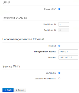
UPnP
UPnP is used by some applications (e.g. DC clients such as FlylinkDC++) to create forwarding rules for TCP/UDP ports used by these applications on a higher router. It is recommended to enable UPnP for operation of file exchange services on a network.
- Enable UPnP – when checked, UPnP is enabled, otherwise – disabled.
Reserved VLAN ID
Reserved VLAN ID – the list of service VLANs, which are used for for solving intrasystem tasks.
- Start VLAN ID – starting VLAN ID value in the reserved range;
- EndVLAN ID – ending VLAN ID value in the reserved range.
Local management via Ethernet
Local management via Ethernet – enables device accessibility without tag via Ethernet.
- Management IP-address – IP address of the Ethernet interface in local network (by deafult 192.0.3.1);
- Netmask – subnet mask.
Service Wi-Fi
- Service Wi-Fi (available only for WB-2P-LR5 rev. C) is used when aligning Wi-Fi (section 3.5 Wi-Fi antenna alignment). With Service Wi-Fi enabled, a Wi-Fi client can connect to the device via an open network with the "EltexWiFi" SSID (2.4 GHz frequency band).
- Wi-Fi enabled – when the Service Wi-Fi flag is on, otherwise, it is disabled. Service Wi-Fi is enabled by default.
- Configuration via HTTP/HTTPS – when checked, configuration via Service Wi-Fi is enabled. Configuration via HTTP/HTTPS is disabled by default.
To apply a new configuration and store settings into the non-volatile memory, click the 'Apply' button. To discard changes click the 'Cancel' button.
To avoid unauthorized access to the device, after aligning Wi-Fi, you should disable the Service Wi-Fi
Configuration example
- Connect PC to LAN port of injector;
- Enter IP address of the device to URL bar of a browser (192.168.1.1 by default, if address was not obtain via DHCP). When connection is established successfully, the window with Login and password fields will be displayed. Fill the filds and click 'Log in'. (By default, login: admin, password: password).
If the window is not displayed make sure that the PC and the device are in the same network.
Implement configuration on Internet tile. In Network Mode field, select the required mode: Bridge or Router. If static settings are used for connection to a provider network, choose 'Static' value in 'Protocol' field and fill the fields: 'IP address', 'Netmask', 'Default gateway', 'Primary DNS Server', 'Secondary DNS Server' – the values are given by service provider.
Configure conection to a base station. Specify SSID of the wireless network, you want to connect to, in the corresponding field. Select security mode through which authentication in the selected wireless network is implemented and specify the key if using an encrypted network. After clicking on the 'Apply' button, the subscriber station will search for the specified SSID on the air and, upon detection, will attempt to connect to the base station with the specified parameters. If the parameters are specified correctly and the signal level is sufficient, a successful connection will occur.
Limiting the number of MAC addresses learned (mac-learning limit)
To enable the functionality of limiting the number of learned MAC addresses, you must connect to the device via telnet/ssh and set a few setup commands.
root@WB-2P-LR5:~$ setconf Internet.Network EnableMacLearningLimit 1 Enable limiting the number of MAC addresses learned. To disable enter 0.
root@WB-2P-LR5:~$ setconf Internet.Network MacLearningLimit 100 Global limiting the number of MAC addresses (Wi-Fi+Ethernet). Possible values: 1-2048. Default – 2048, it is not recommended to change this value.
root@WB-2P-LR5:~$ setconf Internet.Network WifiMacLearningLimit 100 Limiting the number of MAC addresses on the Wi-Fi side. Possible values: 1-2048.
root@WB-2P-LR5:~$ setconf Internet.Network EthMacLearningLimit 100 Limiting the number of MAC addresses on the Ethernet side. Possible values: 1-2048.
root@WB-2P-LR5:~$ setconf Internet.Network DropUnknownUcastSrc 1 Enable the prohibition of transferring traffic from devices whose MAC addresses have not been learned due to exceeding any limit of learned MAC addresses. To disable enter 0.
root@WB-2P-LR5:~$ setconf Internet.Network DropUnknownUcast 1 Enable the prohibition of traffic transfer to unexplored MAC-addresses (unicast only). To disable enter 0.
Spectrum Analyzer
To use the embedded spectrum analyzer on the WB-2P-LR5, you need to login to the device via telnet or ssh. Enter the spectrum-analyzer command to run it. The analysis time for all the radio channels in the range is approximately 5 minutes.
Please note that all clients will disconnect from the base station during spectrum analyzer operation. The subscriber stations will be connected again only when the spectrum analyzer finishes its work.
The result can be obtained using the spectrum-analyzer-result command. Information on the loading of each channel (in percent) will be displayed in the console:
root@WB-2P-LR5:~$ spectrum-analyzer
Spectrum analyzer scanning in progress
root@WB-2P-LR5:~$
root@WB-2P-LR5:~$ spectrum-analyzer-result
================start dump config================
node: Monitoring.Network.SpectrumAnalyzer
		name: 36, value: 5
		name: 37, value: 5
		name: 38, value: 0
		name: 39, value: 3
		name: 40, value: 1
		name: 41, value: 3
		name: 42, value: 0
		name: 43, value: 3
		name: 44, value: 3
		name: 45, value: 3
		name: 46, value: 0
		name: 47, value: 4
		name: 48, value: 2...
Device automatic DHCP-based update algorithm
Device automatic update algorithm is defined by the 'Parameters Priority from' value.
1.If the 'Static settings' value is selected, then the full path (including access protocol and server address) to configuration file and firmware file will be defined by 'Configuration file' and 'Firmware file' Full path should be specified in URL format:
<protocol>://<server address>/<path to file>, where
- <protocol> – protocol used for downloading corresponding files from the server (TFTP is supported);
- <server address> – address of the server with a file to be downloaded (domain name or IPv4);
- <path to file> – path to file on the server.
You can use the following macro in URL (reserved words substituted with the specific values):
- $MA – MAC address – the macro is substituted with device's MAC address in file URL;
- $SN – Serial number – the macro is substituted with device's serial number in file URL;
- $PN – Product name – the macro is substituted with device's model name in file URL (e.g., WB-2P-LR5).
For MAC address, serial number and model name, see 'Device' section on the monitoring page.
URL examples:
tftp://download.server.loc/firmware.file, http://192.168.25.34/configs/WB-2P-LR5//my.cfg ,
tftp://server.tftp/$PN/config/$SN.cfg, http://server.http/$PN/firmware/$MA.frm etc.
Some URL parameters might be omitted. For example, configuration file can be specified in the following format:
http://192.168.18.6
or
config_wb.cfg
If the system is unable to extract the necessary file downloading parameters (protocol, server address or path to file on server) from configuration file or firmware file URL, it will attempt to extract an unknown parameter from DHCP Option 43 (Vendor specific info) or 66 (TFTP server) and 67 (Boot file name), when address obtaining via DHCP is enabled for the Internet service (DHCP option format and analysis will be provided below). If the system is unable to extract missing parameter from DHCP options, default value will be used:
- For protocol: tftp;
- For a server address: update.local;
- For a configuration file name wb-2p-lr5.cfg;
- For a firmware file name wb-2p-lr5.fw.
Thus, if the 'Configuration File' and 'Firmware File' fields are left empty, options 43 or 66, 67 with the location of these files will not be received via DHCP — the URL of the configuration file will look like:
tftp://update.local/wb-2p-lr5.cfg ,
and the firmware file URL:
tftp://update.local/wb-2p-lr5.fw.
2.If 'DHCP options' value is selected, configuration file and firmware file URLs will be extracted from DHCP Option 43 (Vendor specific info) or 66 (TFTP server) and 67 (Boot file name), thus, address obtaining via DHCP should be enabled for the Internet service (DHCP option format and analysis will be provided below). If URL parameters are not provided by DHCP options, default parameters values will be used:
- For protocol: tftp;
- For a server address: update.local;
- For a configuration file name wb-2p-lr5.cfg;
- For a firmware file name wb-2p-lr5.fw.
Option 43 format (Vendor specific info)
1|<acs_url>|2|<pcode>|3|<username>|4|<password>|5|<server_url>|6|<config.file>|7|<firmware.file>|8|<vlan_tag>
1 – TR-069 autoconfiguration server address code;
2 – 'Provisioning code' parameter specification code.
3 – code of the username for TR-069 server authorization;
4 – code of the password for TR-069 server authorization;
5 – server address code; server address is specified in URL format: tftp://address or http://address. The first version represents TFTP server address, the second version – HTTP server address;
6 – configuration file name code;
7 – firmware file name code;
8 – a code of VLAN tag for management;
'|' – mandatory separator used between codes and suboption values.
Algorithm of identification for configuration file and firmware file URL parameters from DHCP Options 43 and 66, 67.
- DHCP exchange initialization
Device initializes DHCP exchange after the startup. - Option 43 analysis
When Option 43 has been received, suboption 8 is analyzed (vlan_tag):
- if there is a suboption and it is different from current VLAN tag, DHCP exchange is initiated in new VLAN;
- suboption is absent or present and does not differ from the current VLAN tag: suboptions with codes 5, 6, and 7 are analyzed to determine the server address and the names of the configuration files and software.
3. Option 66 analysis
If Option 43 is not received from DHCP server or it is received but the system fails to extract the server address, Option 66 will be searched. If the system fails to obtain the firmware file name, Option 67 will be searched. They are used for TFTP server address and the firmware file path extraction respectively. Then, configuration and firmware files will be downloaded from Option 66 address via TFTP.
Special aspects of configuration updates
Configuration file should be in .tar.gz format (this format is used when configuration is saved from the web interface in the 'System' – 'Configuration management' tab). Configuration downloaded from the server will be applied automatically and does not require device reboot.
Special aspects of firmware updates
Firmware file should be in .tar.gz format. When the firmware file is loaded, the device unpacks it and checks its version (using 'version' file in tar.gz archive).
If the current firmware version matches the version of the file obtained via DHCP, firmware will not be updated. Update is performed only when firmware versions are mismatched. When the firmware image is written into the device flash memory, the Power indicator will flash green, orange and red in succession.
Do not power off or reboot the device, when the firmware image is written into the flash memory. These actions will interrupt the firmware update that will lead to the device boot partition corruption. The device will become inoperable. To restore the device operation, use the instruction provided in System recovering after firmware update failure.
System recovering after firmware update failure
If while the firmware update (through the web interface or through autoupdate mechanism based on DHCP) a failure occured (e.g. due to power cutoff) and the device does not operate (the 'Power' indicator is constantly solid red), use the following algorithm to recover the device:
- Unpack the archive with firmware file.
- Connect PC to the device port. Set the following subnet mask on the network interface: 192.168.1.0/24.
- Run the TFTP client on the PC (for Windows, it is recommended to use the Tftpd32), specify 192.168.1.6 as the remote host address, and select the linux.bin file from the unpacked software archive for transfer.
- Launch the command to transmit the file to remote host (Put command). The process of file transmission will be launched.
- If the transmission has started, please, wait for finishing. The device will write the firmware to its memory and launch the system automatically. The time of writing takes approximately 8 minutes. If the process is completed successfully, 'Power' indicator will be green or orange. The configuration of the device before failure is saved. If you can not connect the device, reset it to factory settings.
- If the process has not started, make sure that the network settings of PC are correct and try again. If it does not work, sent the device to maintanence service or proceed recovery using the connection via COM port through a special adapter (if available).
Appendix A. Launch user script when starting the system
Sometimes you need the device to implement certain actions when starting, which cannot be implemented through settings in configuration file. In this case you can configure a user script through a configuration file that will be launched when the system starting. You can set any needed commands sequence.
For user script launching, there is a settings section in the configuration file cfg.yaml:
UserScript:
Enable: "0"
URL: ""
Option 'Enable' permits (if the value is 1) or forbids (if the value is 0) launch of the script, path to which is in URL parameter.
The userscript might be located on remote server as well as on the device. The script is loaded via HTTP or TFTP from remote server. Examples of configuration files for user script launching using different sources are given below:
- Launch from HTTP server
To launch a script from HTTP server, enter the entire path to the file in HTTP-URL format to URL parameter:
URL: " http://192.168.0.250/user-script/script.sh "
In this case, after the device started, file script.sh, which is kept in the catalogue having 192.168.0.250 address, will be automatically loaded via HTTP from the defined server. Then it will be launched. - Launch from TFTP server
To launch a script from TFTP server, enter the entire path to the file in TFTP-URL format to URL parameter:
URL: " tftp://192.168.0.250/user-script/script.sh "
In this case, after the device started, file script.sh, which is kept in the catalogue having 192.168.0.250 address, will be automatically loaded via TFTP from the defined server. Then it will be launched. - Local script launch
Due to the peculiar properties of the file system, a local script should be stored in /etc/config catalogue as the content of the catalogue is saved after device reload. You can create script in /etc/config catalogue through vi editor or load it from TFTP server using tftp –gl sh <TFTP-server address> command. After creating a script, you should set rights for launching using the following command:
chmod 777 /etc/config/user.sh
In configuration file, URL for local script launching should be set as follows:
URL: " File://etc/config/user.sh "
A user script should start from the #!/bin/sh directive.
Appendix B. Antenna Patterns
The pattern of vertically polarized antenna in H-plane:
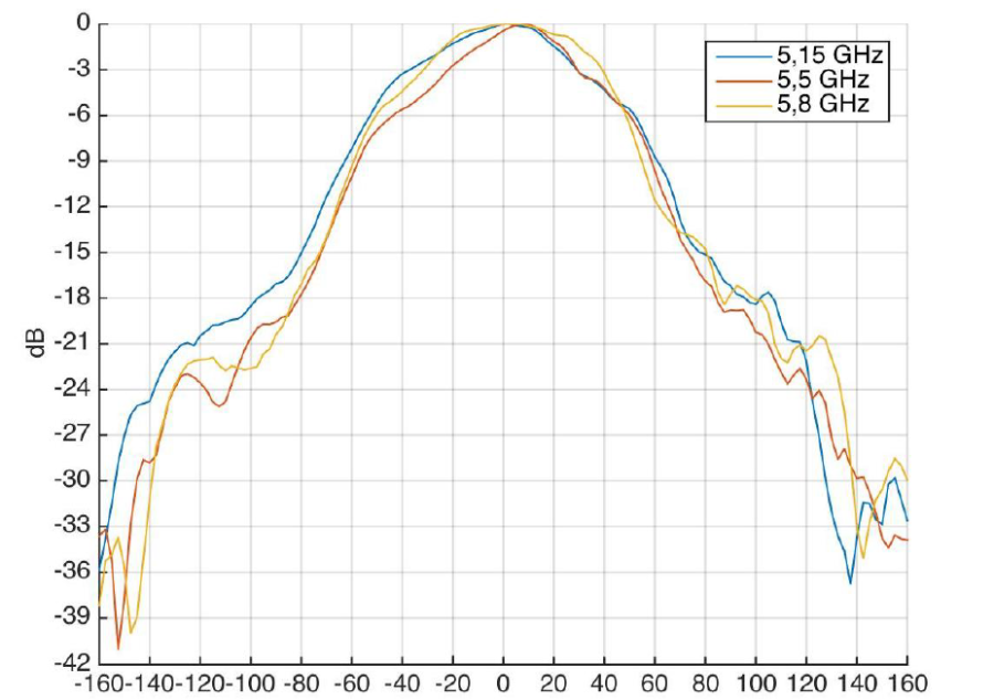
The pattern of vertically polarized antenna in E-plane:
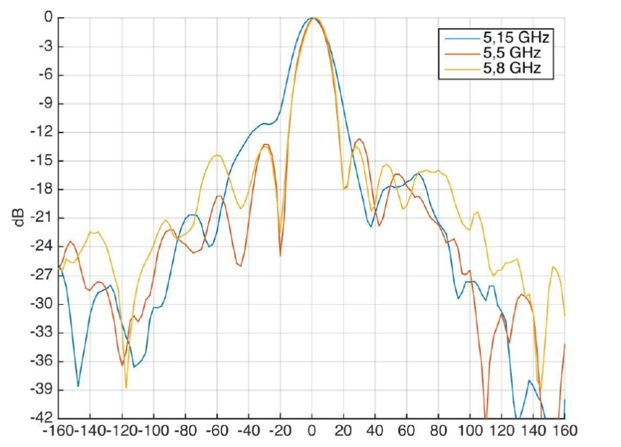
The pattern of horizontally polarized antenna in H-plane:
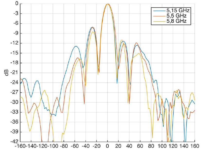
The pattern of horizontally polarized antenna in E-plane:
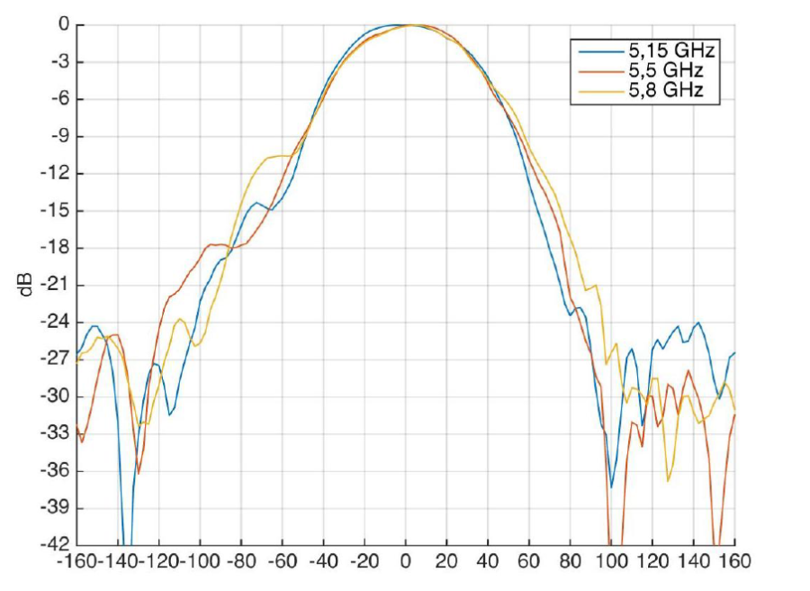
The list of changes
Document version | Issue date | Revisions |
|---|---|---|
| Version 7.0 | 30.01.2022 | Synchronization with firmware version 2.6.0 Changed:
|
| Version 6.0 | 11.10.2021 | Synchronization with firmware version 2.5.0 Added:
Changed:
|
| Version 5.1 | 22.12.2020 | Synchronization with firmware version 2.4.1 |
| Version 5.0 | 07.04.2020 | Synchronization with firmware version 2.4.0 Added: Changes in sections: |
| Version 4.0 | 06.11.2019 | Synchronization with firmware version 2.3.0 Changes in sections:
|
Version 3.0 | 28.06.2019 | Synchronization with firmware version 2.2.0 Added:
|
| Version 2.0 | 31.10.2018 | Added: 4.5.3 Wireless bridge 4.6.4 'WDS' submenu 4.6.5 'Radiointerface' submenu 4.7.2 'WDS' submenu Changes in chapters: 2.2 Device specifications 4.6.3 'Internet' submenu 4.6.7 'MAC addresses confinuration' submenu' |
Version 1.0 | 24.11.2017 | First issue |
Firmware version |
| 2.6.0 |