Wireless access point WEP-3ax, WEP-3ax-Z
User manual,
Firmware version 1.6.0 (03.2022)
IP address: http://192.168.1.10
User name: admin
Password: password
Introduction
Annotation
Modern tendencies of telecommunication development necessitate operators to search for the most optimal technologies, allowing to satisfy rapidly growing needs of subscribers, maintaining at the same time consistency of business processes, development flexibility and reduction of costs of various services provision. Wireless technologies are spinning up more and more and have paced a huge way for short time from unstable low-speed communication networks of low radius to broadband networks equitable to speed of wired networks with high criteria to the quality of provided services.
WEP-3ax, WEP-3ax-Z are dedicated to be installed inside buildings as an access points and to create a seamless wireless network using several identical access points ("Roaming") on a large area.
This manual specifies intended purpose, main technical parameters, design, safe operation rules and installation and configuration recommendations for WEP-3ax and WEP-3ax-Z.
Symbols
Notes and warnings
Notes contain important information, tips or recommendations on device operation and setup.
Warnings are used to inform the user about harmful situations for the device and the user alike, which could cause malfunction or data loss.
Device description
Purpose
WEP-3ax and WEP-3ax-Z wireless access points are designed to provide users with access to high-speed and safe network.
The devices are dedicated to create L2 wireless networks interfacing with a wired network. WEP-3ax and WEP-3ax-Z are connected to a wired network via 100/1000/2500M Ethernet interface and arrange high-speed access to the Internet for devices supporting Wi-Fi technology at 2.4 and 5 GHz.
The devices have two radio interfaces to organize two physical wireless networks.
WEP-3ax and WEP-3ax-Z support up-to-date requirements to service quality and allow transmitting more important traffic in higher priorities queues. Prioritization is based on the main QoS technologies: CoS (Special tags in the VLAN packet field) and ToS (tags in the IP packet field).
Support for traffic shaping on each VAP allows to fully manage service quality and restrictions, both for all subscribers and for everyone in particular.
The devices are designed to be installed in offices, state buildings, conference halls, laboratories, hotels, etc. The creation of virtual access points with different types of encryption allows clients to delimit access rights among users and groups of users.
Device specification
Interfaces:
- 1 port of Ethernet 100/1000/2500BASE-T(RJ-45) with PoE+ support;
- Wi-Fi 2.4 GHz IEEE 802.11b/g/n/ax;
- Wi-Fi 5 GHz IEEE 802.11a/n/ac/a.
Functions:
WLAN capabilities:
- Support for IEEE 802.11a/b/g/n/ac/ax standards;
- Support for roaming IEEE 802.11r/k/v;
- Data aggregation, including A-MPDU (Tx/Rx) and A-MSDU (Rx);
- WMM-based priorities and packet planning;
- Dynamic frequency selection (DFS);
- Support for hidden SSID;
- 32 virtual access points;
- Third-party access point detection;
- Spectrum analyzer;
- Channel autoselection.
Network functions:
- Autonegotiation of speed, duplex mode and switching between MDI and MDI-X modes;
- Support for VLAN;
- 802.1X authentication support (EAP-PEAP/TLS/TTLS);
- NTP;
- GRE;
- DHCP client.
QoS functions:
- Bandwidth limiting for each SSID;
- Client data rate limiting for each SSID;
- Support for prioritization by CoS and DSCP.
Security:
- Centralized authorization via RADIUS server (WPA Enterprise);
- WPA/WPA2/WPA3 data encryption;
- Support for Captive Portal.
Figure 1 shows WEP-3ax/WEP-3ax-Z use case.
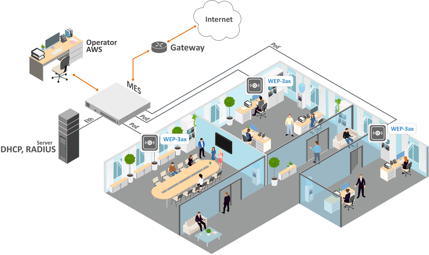
Figure 1 – WEP-3ax/WEP-3ax-Z application diagram
Device technical parameters
Table 1 – Main Specifications
WAN Ethernet interface parameters | |
|---|---|
Number of ports | 1 |
Electrical connector | RJ-45 |
Data rate | 100/1000/2500 Mbps, auto-negotiation |
Standards | BASE-T |
Wireless interface parameters | |
Standards | 802.11a/b/g/n/ac/ax |
Frequency range | 2402–2482 MHz, 5170–5835 MHz |
Modulation | DSSS, CCK, BPSK, QPSK, 16QAM, 64QAM, 256QAM, 1024QAM |
Operating channels | 802.11b/g/n/ax: 1–13 (2402–2482 MHz) 802.11a/n/ac/ax:
|
Speed of data transmission | 2.4 GHz, 802.11ax: 574 Mbps |
| Maximum number of concurrent sessions | 2.4 GHz: 512 5 GHz: 512 |
Maximum output power of the transmitter | 2.4 GHz: up to 22.5 dBm |
Receiver sensitivity | 2.4 GHz: up to -92 dBm |
Security | Centralized authorization via RADIUS server (WPA Enterprise) |
Support for 2x2 MIMO | |
Control | |
Remote control | Web interface, Telnet, SSH, NETCONF, EMS management system |
Access restriction | by password |
General parameters | |
Flash memory | 256 MB NAND Flash |
RAM | 1 GB RAM DDR4 |
Power supply | PoE+ 48V/56V (IEEE 802.3at-2009) |
Power consumption | no more than 13 W |
Range of operation temperatures | from +5 to +40°C |
Relative humidity at 25°C | up to 80% |
Dimensions (Diameter x Height) | 230x56 mm |
Weight | 0.56 kg |
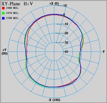
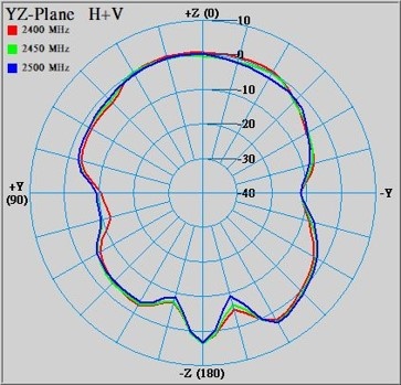
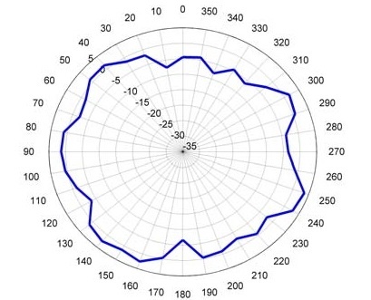
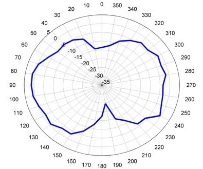
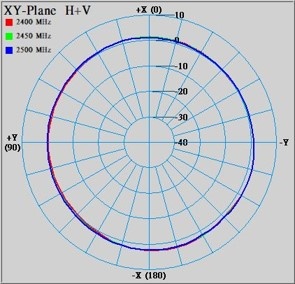
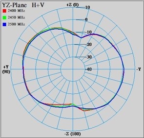
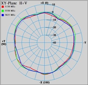
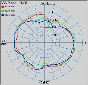
Radiation patterns
Radiation patterns for the embedded antennas are given below.
Radiation patterns for 2v1 and 2v2 board revisions are different.
WEP-3ax 2v1 | |
|---|---|
|
|
2.4 GHz | |
|
|
5 GHz | |
|
|
WEP-3ax 2v2 | |
|
|
2.4 GHz | |
|
|
5 GHz | |
|
|


Design
WEP-3ax and WEP-3ax-Z are enclosed in plastic case.
Device main panel
The main panel layout of the device is depicted in Figure 2.
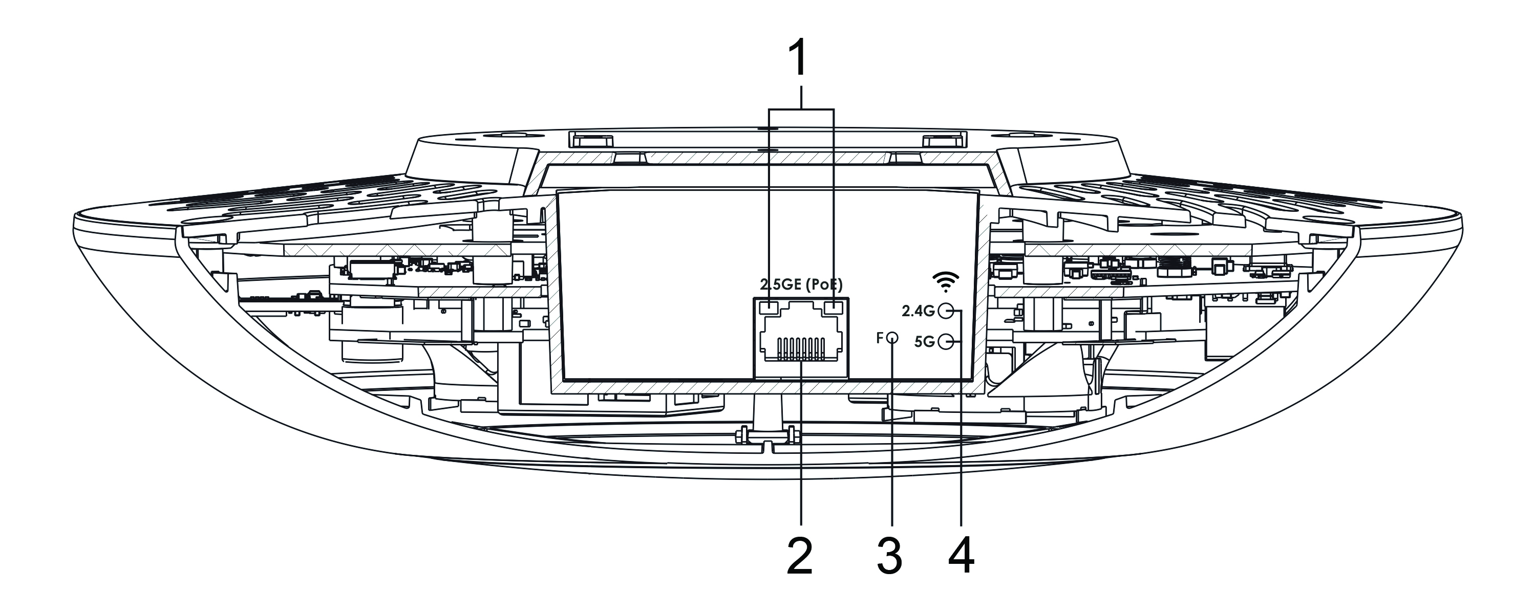
Figure 2 – Main panel of the device
The following light indicators, connectors and controls are located on the main panel of WEP-3ax/WEP-3ax-Z (Table 2).
Table 2 – Description of ports and controls
Front panel element | Description | |
|---|---|---|
1 | LAN | 2.5GE (PoE) port status light indication |
2 | 2.5GE (PoE) | 2.5GE port for Ethernet cable and PoE+ power supply |
3 | F | Button for resetting to factory settings |
4 | Wi-Fi | Operation indicators of corresponding Wi-Fi modules |
Light indication
The current device state is displayed by Wi-Fi, LAN, Power indicators. The list of indicators’ possible states is given below.
Table 3 – Light indication of device state
Indicator | Indicator status | Device state |
|---|---|---|
Wi-Fi | solid green | Wi-Fi network is active |
flashing green | the process of data transmission trough a wireless network | |
LAN | solid green (100 Mbps)/solid orange (1000, 2500 Mbps) | the link with the connected network device is established |
flashing green | the process of packet data transmission through LAN interface | |
Power | solid green | device power on, normal operation |
solid orange | the device is loaded but IP address is not received via DHCP | |
solid red | the device is loading |
Reset to the default settings
To reset the device to factory settings, press and hold the "F" button until the "Power" indicator starts flashing. Device will be rebooted automatically. DHCP client will be launched by default. If the address is not obtained via DHCP, the device will have the default IP address – 192.168.1.10, and the following netmask – 255.255.255.0.
Delivery package
The delivery package includes:
- Wireless access point WEP-3ax/WEP-3ax-Z;
- Mounting kit;
- User manual on a CD (optionally);
- Conformity certificate;
- Technical passport.
Rules and recommendations for device installation
This section defines safety rules, installation recommendations, setup procedure and the device starting procedure.
Safety rules
- Do not install the device close to heat sources or in rooms with temperature below 5 °C or above 40 °C.
- Do not use the device in places with high humidity. Do not expose the device to smoke, dust, water, mechanical vibrations or shocks.
- Do not open the device case. There are no user serviceable parts inside.
Do not cover ventilation holes and do not put other objects on the device in order to prevent overheating of device components.
Installation recommendations
- Recommended mounting position: horizontal, on the ceiling.
- Before you install and enable device, check the device for visible mechanical defects. If defects are observed, you should stop the device installation, draw up corresponding act and contact the supplier.
- If the device has been exposed for a long time at a low temperature, it must be left to stand for two hours at room temperature before use. After a long stay of the device in conditions of high humidity, let it stand under normal conditions for at least 12 hours before switching on.
- During the device installation, follow these rules to ensure the best Wi-Fi coverage:
- Install the device at the center of a wireless network;
- Minimize the number of obstacles (walls, roof, furniture and etc.) between access point and other wireless network devices;
- Do not install the device near (about 2 m) electrical and radio devices;
- It is not recommended to use radiophone and other equipment operating on the frequency of 2.4 GHz, 5 GHz in Wi-Fi effective radius;
- Obstacles in the form of glass/metal constructions, brick/concrete walls, water cans and mirrors can significantly reduce Wi-Fi action radius. It is not recommended to place the device inside a false ceiling as metal frame causes multipath signal propagation and signal attenuation.
- During the installation of several access points, cell action radius must overlap with action radius of a neighboring cell at level of -65 ÷ -70 dBm. Decreasing of the signal level on cells borders to -75 dBm is permitted if it involves the use of VoIP, streaming video and other traffic that is sensitive to losses in wireless network.
Calculating the number of required access points
To calculate the required number of access points, you should evaluate the required coverage zone. For a more accurate assessment, it is necessary to make a radio examination of the room. Approximate coverage radius of confident reception of WEP-3ax, WEP-3ax-Z access points when mounted on the ceiling in a typical office space: 2.4 GHz – 40-50 m, 5 GHz – 20-30 m. If there are no obstacles, range: 2.4 GHz – up to 100 m; 5 GHz – up to 60 m.
Table 4 describes approximate attenuation values.
Table 4 – Attenuation values
Material | Change of signal level, dB | |
|---|---|---|
2.4 GHz | 5 GHz | |
Organic glass | -0.3 | -0.9 |
Brick | -4.5 | -14.6 |
Glass | -0.5 | -1.7 |
Plaster slab | -0.5 | -0.8 |
Wood laminated plastic | -1.6 | -1.9 |
Plywood | -1.9 | -1.8 |
Plaster with wirecloth | -14.8 | -13.2 |
Breezeblock | -7 | -11 |
Metal lattice (mesh 13*6 mm, metal 2mm) | -21 | -13 |
Channel selection for neighboring access points
It is recommended to set nonoverlapping channels to avoid interchannel interference among neighboring access points.

Figure 3 – General diagram of frequency channel closure in the range of 2.4 GHz
For the example of channel allocation scheme among neighboring access points in frequency range of 2.4 GHz when channel width is 20 MHz, see Figure 4.

Figure 4 – Scheme of channel allocation among neighboring access points in the frequency range of 2.4 GHz when channel width is 20 MHz
Similarly, the procedure of channel allocation is recommended to save for access point allocation between floors, see Figure 5.
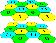
Figure 5 – Scheme of channel allocation between neighboring access points that are located between floors
When width of used channel is 40 MHz there is no non-overlapping channels in frequency range of 2.4 GHz. In such cases, you should select channels maximally separated from each other.
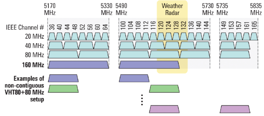
Figure 6 – Channels used in range of 5 GHz when channel width is 20, 40 or 80 MHz
Device installation
The device should be attached to plain surface (wall or ceiling) in accordance with the safety instruction and recommendations listed above.
The device delivery package includes required mounting kit to attach the device to plain surface.
Wall mounting
1. Fix the bracket (included in the delivery package) to the wall:
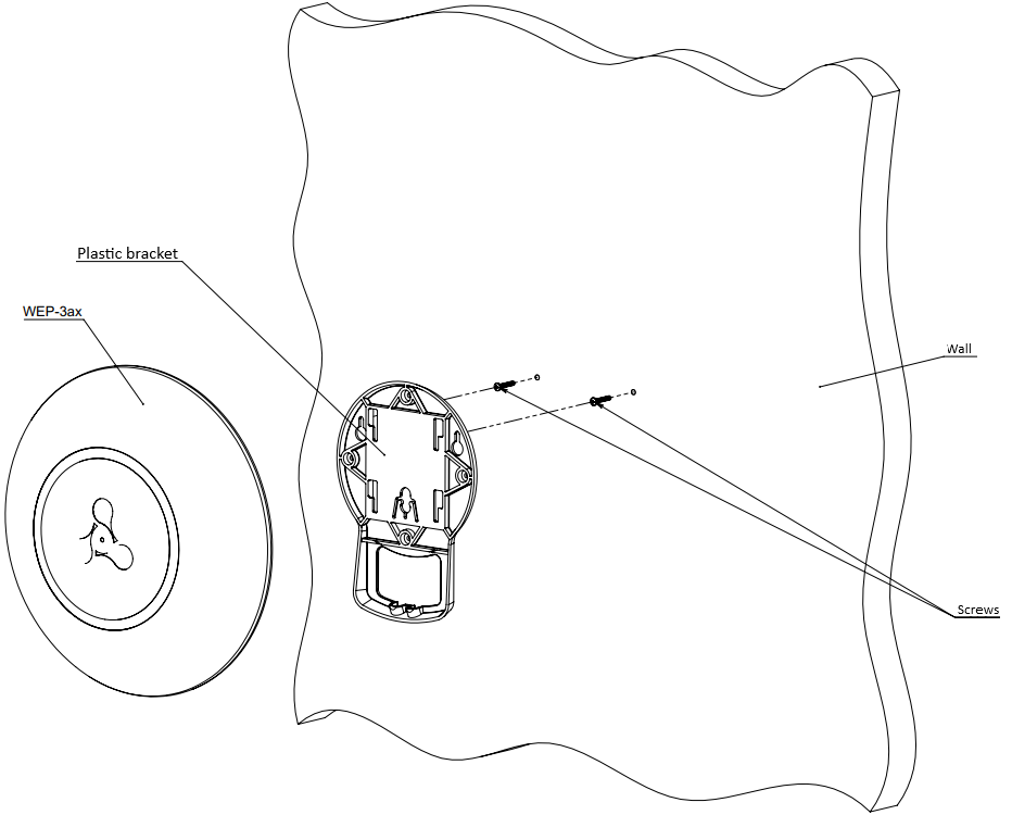
Figure 7 – Attaching the bracket to a wall
- The figure shows the bracket allocation.
- When installing the bracket, pass wires through the corresponding channels of the bracket, see Figure 7.
- Pass the wires into the corresponding grooves on the bracket while installing the bracket. Screw the brackets to the device surface by using screwdriver.
2. The device installation
- Connect cables to corresponding connector of the device. Description of the connectors is given in section Design.
- Align the device with the bracket and lock the position by pulling it down.
Installing to false ceiling
It is not recommended to place the device inside a false ceiling as metal frame causes multipath signal propagation and signal attenuation.
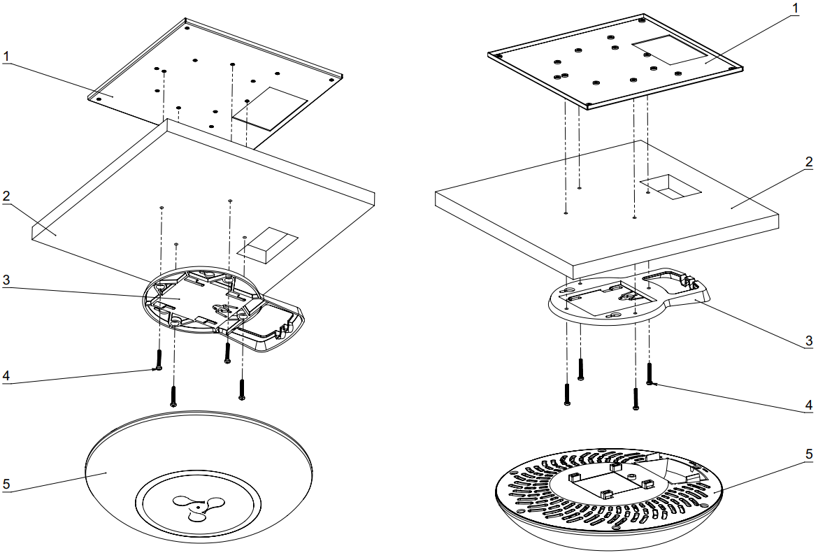
1 – metal bracket; 2 – Armstrong panel; 3 – plastic bracket; 4 – bolt; 5 – device.
Figure 8 – Mounting to a false ceiling
- Fasten metal and plastic bracket on a ceiling as shown in Figure 8.
- The plastic bracket (3) connects to the metal bracket (1) on the false ceiling in the following order: metal bracket -> Armstrong panel -> plastic bracket.
- Cut the hole in the Armstrong panel. The size of the hole should be equal to hole of metal bracket. Conduct wires through the hole.
- Align holes in metal bracket with holes of Armstrong panel and plastic bracket. Align together three screw holes on the plastic bracket and the screw holes on the metal bracket. Screw the brackets to the device surface by using a screwdriver.
- Install the device.
- Connect cables to corresponding connector of the device. Description of the connectors is given in section Design.
- Align the device and plastic bracket together, fix the position, turning clockwise.
Removing the device from the bracket
For removing the device from the bracket:
- Pull the device up, Figure 7.
- Remove the device.
Device management via the web interface
Getting started
To get started, connect to the device via WAN interface using a web browser:
1. Open a web browser, for example, Firefox, Opera, Chrome.
2. Enter the device IP address in the browser address bar.
The default IP-address of the device – 192.168.1.10, subnet mask – 255.255.255.0 The device is capable to obtain an IP address via DHCP.
When the device is successfully detected, username and password request page will be shown in the browser window:
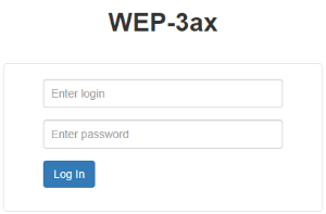
3. Enter your username into "Login" and password into "Password" field.
Factory default: login: admin, password: password.
4. Click the "Log In" button. A menu for monitoring the status of the device will open in a browser window.

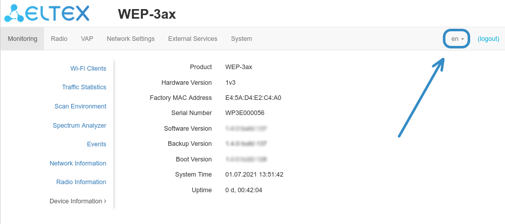
5. If necessary, you can switch the information display language. WEP-3ax, WEP-3ax-Z support Russian and English versions of the web interface.
Applying configuration and discarding changes
- Applying configuration
Clicking on the  button starts the process of saving the configuration to the device flash memory and applying the new settings. All the settings come into operation without device rebooting.
Visual indication of the process current status of the setting application process is realised in the web interface, Table 5.
Table 5 – Visual indication of the current status of the setting application process
| Image | State description |
|---|---|
| After clicking "Apply", the process of settings saving to device memory is launched. The |
| Successful settings saving and application are indicated by the |

2. Discarding changes
You can discard changes only before clicking the "Apply" button. If you click the "Apply" button, all the changed parameters will be applyed and saved to device memory. You will not be able to return to previous configuration after clicking "Apply".
The button for discarding changes appears as follows:  .
.
Web interface basic elements
Navigation elements of the web interface are shown on the figure below.
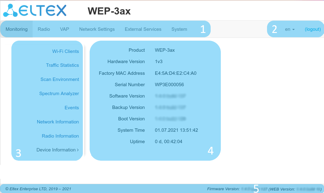
User interface window is divided into five general areas:
- Menu tabs categorize the submenu tabs: Monitoring, Radio, VAP, Network Settings, External Services, System.
- Interface language selection and Logout button designed to end a session in the web interface under a given user.
- Submenu tabs allow you to control settings field.
- Devcie configuration field displays data and configuration.
- Information field showing the firmware and web interface versions.
"Monitoring" menu
In the "Monitoring" menu you can view the current system state.
"Wi-Fi Clients" submenu
The "Wi-Fi clients" submenu displays information about the status of connected Wi-Fi clients.
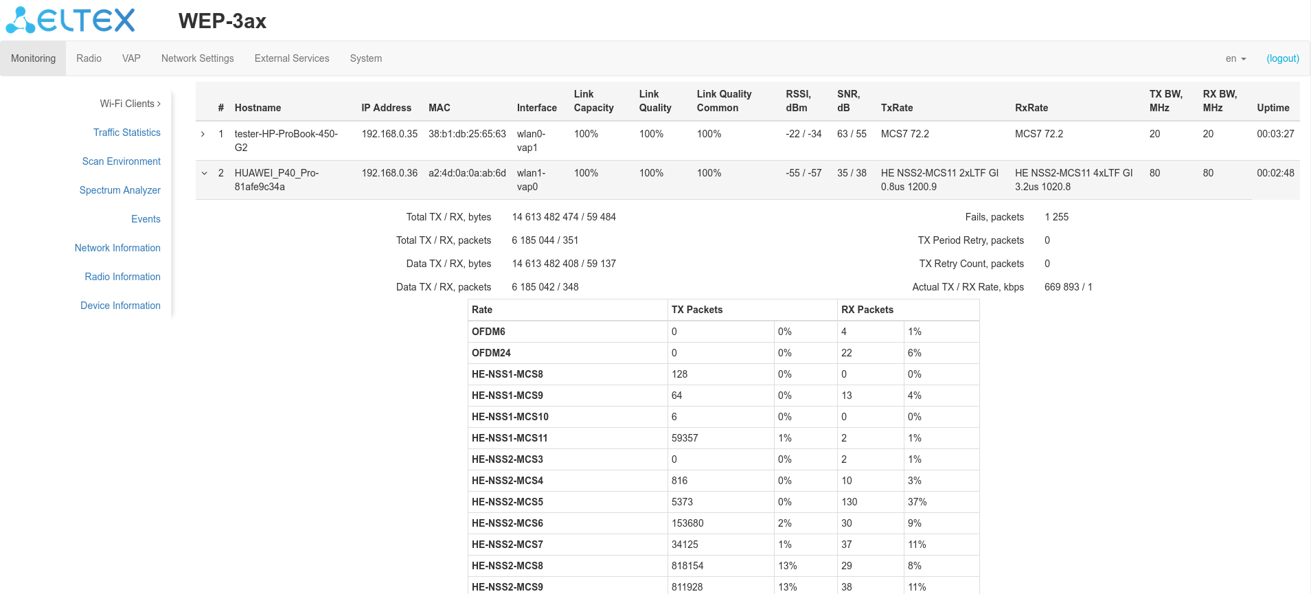
- # – number of the connected device in the list;
- Hostname – network name of the device;
- IP Address – IP address of the connected device;
- MAC – MAC address of the connected device;
- Interface – WEP-3ax, WEP-3ax-Z interface for interaction with the connected device;
- Link Capacity – parameter that reflects the effectiveness of the use of a modulation access point on the transmission. It is calculated based on the number of packets transmitted on each modulation to the client, and the reduction factors. The maximum value is 100% (means that all packets are transmitted to the client at maximum modulation for the maximum nss type supported by the client). The minimum value is 2% (in the case when the packets are transmitted to the modulation nss1mcs0 for a client with MIMO 3x3 support). The parameter value is calculated for the last 10 seconds;
- Link Quality – parameter that displays the status of the link to the client, calculated based on the number of retransmit packets sent to the client. The maximum value is 100% (all transmitted packets were sent on the first attempt), the minimum value is 0% (no packets were successfully sent to the client). The parameter value is calculated for the last 10 seconds;
- Link Quality Common – parameter that displays the status of the link to the client, calculated based on the number of retransmit packets sent to the client. The maximum value is 100% (all transmitted packets were sent on the first attempt), the minimum value is 0% (no packets were successfully sent to the client). The parameter value is calculated for the entire client connection time;
- RSSI – received signal level, dBm;
- SNR – signal/noise ratio, dB;
- TxRate – channel data rate of transmission, Mbps;
- RxRate – channel data rate of receiving, Mbps;
- Tx BW – transmission bandwidth, MHz;
- Rx BW – reception bandwidth, MHz;
- Uptime – Wi-Fi client connection uptime.
To display more detailed information on a particular client, select it from the list. A detailed description includes the following options:
- Total TX/RX, bytes – the number of bytes sent/received on the connected device;
- Total TX/RX, packets – the number of packets sent/received on the connected device;
- Data TX/RX, bytes – the number of data bytes sent/received on the connected device;
- Data TX/RX, packets – the number of data packets sent/received on the connected device;
- Fails, packets – the number of packets sent with errors on the connected device;
- TX Period Retry, packets – the number of retries of transmission to the connected device in the last 10 s;
- TX Retry Count, packets – the number of retries of transmission to the connected device during the entire connection;
- Actual TX/RX Rate, kbps – the current traffic transmission rate at the moment.
"Traffic Statistics" submenu
"Traffic Statistics" section displays the diagrams of the speed of the transmitted/received traffic for the last 3 minutes, as well as statistics on the amount of transmitted/received traffic since the access point was turned on.
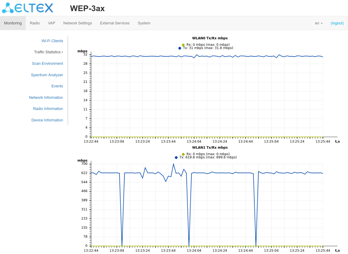
The WLAN0 and WLAN1 Tx/Rx diagrams show the last 3 minutes rate of transmitted/received traffic via Radio 2.4 GHz (WLAN0) and Radio 5 GHz (WLAN1) access point interfaces. The diagram is automatically updated every 2 seconds.
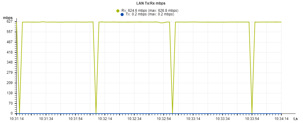
The LAN Tx/Rx diagram shows the speed of the transmitted/received traffic via the access point's Ethernet interface in the last 3 minutes. The diagram is automatically updated every 2 seconds.
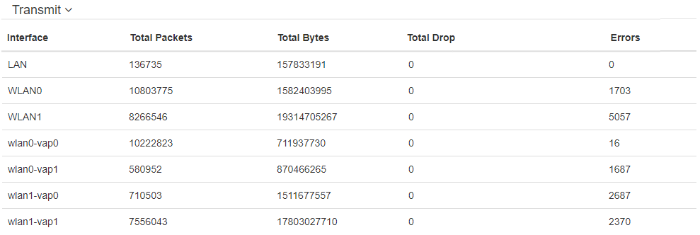
"Transmit" table description:
- Interface – name of the interface;
- Total Packets – number of successfully sent packets;
- Total Bytes – number of successfully sent bytes;
- Total Drop – number of rejected packets;
- Errors – number of errors.
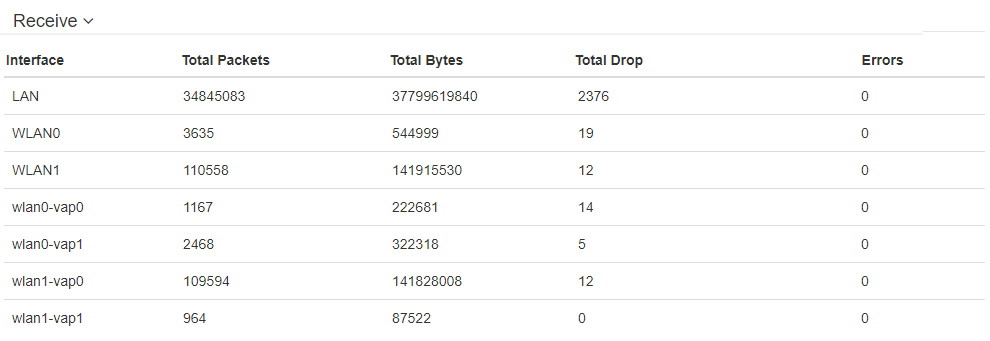
"Receive" table description:
- Interface – name of the interface;
- Total Packets – number of successfully received packets;
- Total Bytes – number of successfully received bytes;
- Total Drop – number of rejected packets;
- Errors – number of errors.
"Scan Environment" submenu
"Scan Environment" submenu allows scanning of the surrounding radio to detect neighboring access points.
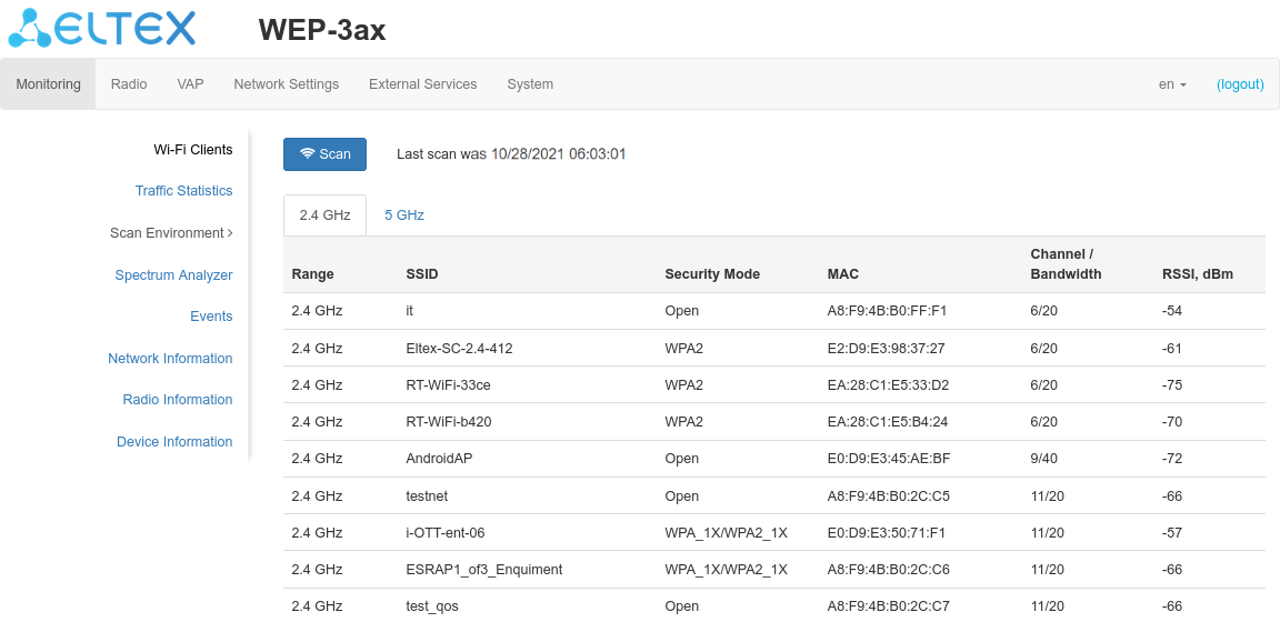
Click the "Scan" button to start the environment scanning process. When the process is complete, the page will display a list of detected access points and information about them:
- Last scan was... – last scan date and time;
- Range – specifies the range of 2.4 GHz or 5 GHz to which the access point was detected;
- SSID – SSID of the detected access point;
- Security Mode – security mode of the detected access point;
- MAC – MAC address of the detected access point;
- Channel/Bandwidth– radio channel on which the detected access point operates;
- RSSI – the level with which the device receives the signal of the detected access point, dBm.
Please note that during the environment scan, the device’s radio interface will be disabled, which will make it impossible to transfer data to Wi-Fi clients during the scan.
"Spectrum Analyzer" submenu
In "Spectrum Analyzer" submenu the spectrum analyzer is started and monitored.
Running the spectrum analyzer on radio interfaces
Note that running the spectrum analyzer on the radio interface (Radio 2.4 GHz or Radio 5 GHz) will put it into scanning mode, which will disable all Wi-Fi clients connected to that radio interface.
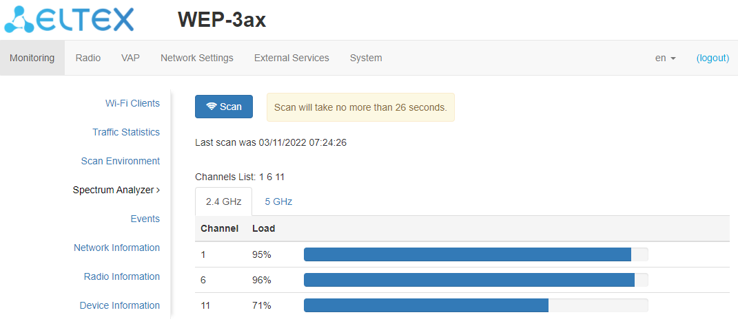
Click the "Scan" button to start the spectrum analyzer. The information window to the right of the button displays the time in seconds that has elapsed since the start of scanning. The time of the spectrum analyzer on the Radio 2.4 GHz radio interface does not exceed 106 seconds, on the Radio 5 GHz does not exceed 138 seconds.
- Last scan was... – last scan date and time;
- Channels list – list of channels to be scanned;
- Channel – number of the channel on which the scan was performed;
- Load – information about radio channel load, expressed as a percentage.
The spectrum analyzer on the radio interface operates only on channels that are reflected in the "Channels List" parameter. For example, if the Radio 2.4 GHz channel list contains channels '1 6 11', the spectrum analysis will only be performed for channels 1, 6 and 11. To add/remove channels from this list, go to the tab corresponding to this radio interface on the "Radio" page and make changes in the "Use Limit Channels" parameter.
In order to analyze all the channels of the band on which the radio interface operates, go to the tab corresponding to the radio interface on the "Radio" page and uncheck the option "Use Limit Channels". After receiving the results of the spectrum analyzer, check the "Use Limit Channels" option again.
For more information about configuring the radio interface via web interface, see section The "Radio" menu.
"Events" submenu
In this section, you can view a list of real-time informational messages which contains the following information:
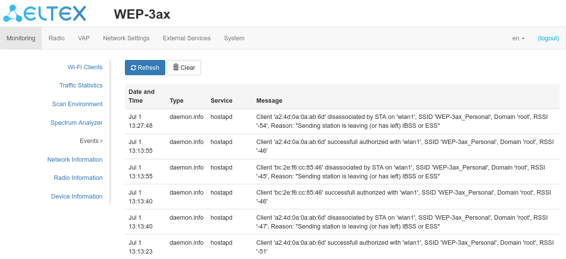
- Date and Time – time when event was generated;
- Type – category and importance level of the event;
- Service – name of the process that generated the message;
- Message – event description.
Table 6 – Event importance categories description
Level | Message importance level | Description |
|---|---|---|
0 | Emergency | A critical error has occurred in the system, the system may not work properly. |
1 | Alert | Immediate intervention is required. |
2 | Critical | A critical error has occurred on the system. |
3 | Error | An error has occurred on the system. |
4 | Warning | Warning, non-emergency message. |
5 | Notice | System notice, non-emergency message. |
6 | Informational | Informational system messages. |
7 | Debug | Debugging messages provide the user with information to correctly configure the system. |
To receive new messages in the event log, click the "Refresh" button.
If necessary, you can delete all old messages from the log by clicking on the "Clear" button.
"Network Information" submenu
In "Network Information" submenu you can view common network settings of the device.
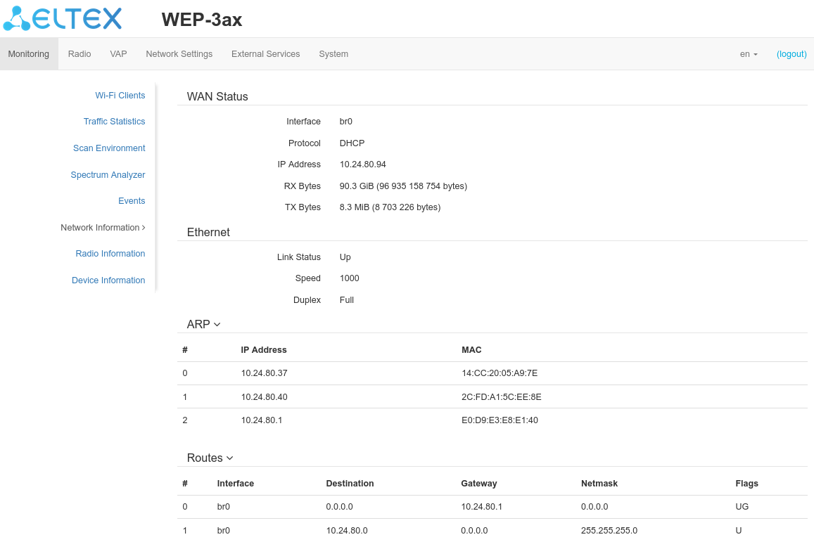
WAN Status:
- Interface – name of the interface;
- Protocol – a protocol which is used for access to WAN;
- IP Address – device IP address in external network;
- RX Bytes – number of bytes received on WAN;
- TX Bytes – number of bytes sent from WAN.
Ethernet:
- Link Status – Ethernet port status;
- Speed – Ethernet port connection speed;
- Duplex – data transfer mode:
- Full – full duplex;
- Half – half-duplex.
ARP:
The ARP table contains information about the alignment between the IP and MAC addresses of neighboring network devices:
- IP Address – device IP address;
- MAC – device MAC address.
Routes:
- Interface – name of the interface;
- Destination – IP address of destination host or subnet that the route is established to;
- Gateway – gateway IP address that allows for the access to the Destination;
- Netmask – subnet mask;
- Flags – certain route characteristics. The following flag values exist:
- U – means that the route is created and passable;
- H – identifies the route to the specific host;
- G – means that the route lies through the external gateway; System network interface provides routes in the network with direct connection. All other routes lie through the external gateways. G flag is used for all routes except for the routes in the direct connection networks;
- R – indicates that the route was most likely created by a dynamic routing protocol running on the local system using the reinstate parameter;
- D – indicates that the route was added as a result of receiving an ICMP Redirect Message. When the system learns the route from the ICMP Redirect message, the route will be added into the routing table in order to exclude redirection of the following packets intended for the same destination;
- M – means that the route was modified – likely by a dynamic routing protocol running on a local system with the "mod" parameter applied;
- A – points to a buffered route to which an entry in the ARP table corresponds;
- C – means that the route source is the core routing buffer;
- L – indicates that the destination of the route is one of the addresses of this computer. Such "local routes" exist in the routing buffer only;
- B – means that the route destination is a broadcasting address. Such "broadcast routes" exist in the routing buffer only;
- I – indicates that the route is connected to a ring (loopback) interface for a purpose other than to access the ring network. Such "internal routes" exist in the routing buffer only;
- ! – means that datagrams sent to this address will be rejected by the system.
"Radio Information" submenu
"Radio Information" submenu displays the current status of WEP-3ax, WEP-3ax-Z radio interfaces.
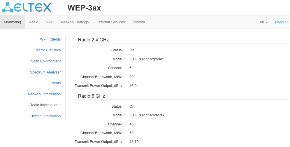
Radio interfaces of an access point may be in two states: "On" and "Off". The status of each of the radio interfaces is reflected in the "Status" parameter.
Radio status depends on whether a given radio interface has virtual access points (VAP) enabled. If there is at least one active VAP on the radio interface, Radio will be in the "On" status, otherwise – "Off".
Depending on Radio status, the following information is available for monitoring:
"Off":
- Status – radio interface status.
"On":
- Status – radio interface status;
- Mode – radio interface operation mode according to IEEE 802.11 standards;
- Channel – number of the wireless channel on which the radio interface operates;
- Channel Bandwidth – the bandwidth of the channel where the radio interface operates, MHz;
- Transmit Power Output – actual power of the transmitter, dBm.
"Device Information" submenu
"Device Information" submenu displays main WEP-3ax, WEP-3ax-Z parameters.
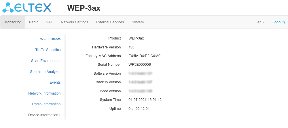
- Product – device model name;
- Hardware Version – device hardware version;
- Factory MAC Address – device WAN interface MAC address, setted by manufacturer;
- Serial Number – device serial number, setted by manufacturer;
- Software Version – device firmware version;
- Backup Version – previously installed firmware version;
- Boot Version – device firmware boot version;
- System Time – current time and date, setted in system;
- Uptime – the time since the last turn on or restart the device.
"Radio" menu
In "Radio" menu you can configure the wireless interface.
"Radio 2.4 GHz" submenu
In "Radio 2.4 GHz" submenu you can configure the main parameters of the radio interface of the device operating in the 2.4 GHz band.
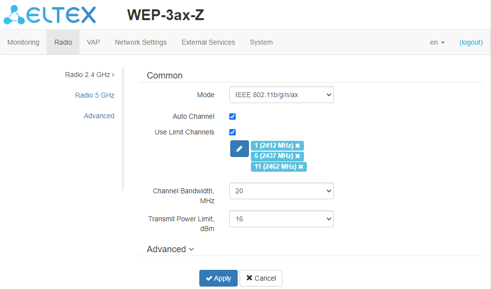
- Mode – select interface operation mode:
- IEEE 802.11ax;
- IEEE 802.11b/g/n;
- IEEE 802.11b/g/n/ax.
- Auto Channel – when checked, the device will automatically select the least loaded radio channel for the Wi-Fi interface. Removing the flag opens the access to install the static operation channel;
- Channel – select channel for data transmission;
- Use Limit Channels – when checked, the access point will use a user-defined list of channels to work in automatic channel selection mode. If the "Use Limit Channels" flag is not checked or there are no channels in the list, the access point will select the operation channel from all available channels in the given band. 2.4 GHz range channels: 1-13;
- Channel Bandwidth, MHz – the bandwidth of the channel where the radio interface operates. Can take a value of 20 or 40 MHz;
- Primary Channel – the parameter can only be changed if the bandwidth of a statically specified channel is equal to 40 MHz. The 40 MHz channel can be considered as consisting of two 20 MHz channels, which border in the frequency range. These two 20 MHz channels are called primary and secondary channels. The primary channel is used by clients who only support 20 MHz channel bandwidth:
- Upper – the primary channel will be the upper 20 MHz channel in the 40 MHz band;
- Lower – the primary channel will be the lower 20 MHz channel in the 40 MHz band.
- Transmit Power Limit, dBm – transmitting Wi-Fi signal power adjustment, dBm. May take values between 6 and 16 dBm.
If the "Use Limit channels" list contains a channel that is not available for selection, it will be marked in grey. In order for the new configuration to be applied to an access point, only available (blue highlighted) channels must be specified in the "Use Limit channels" list.
Example. No settings have been made on the access point yet, Radio 2.4 GHz is set to 20 MHz "Channel Bandwidth" by default, and channels are specified in the "Use Limit Channels" list: 1, 6, 11.
Suppose the parameter "Channel Bandwidth" is set to 40 MHz. When you change this parameter from 20 MHz to 40 MHz, the following happens:
- The "Primary Channel" parameter becomes available for editing and the default value is "Lower",
- Channel 11 in the "Use Limit Channels" list changes its color from blue to gray.
If you change the "Channel Bandwidth" parameter to 40 MHz and do not remove the "grey" channels from the list, then when you click the "Apply" button in the browser an error will appear – "There are errors in data. Changes was not applied". Accordingly, the access point configuration will not be changed. This is due to the fact that channels in the "Use Limit Channels" list that are highlighted in grey do not fit the definition "Primary channel" = Lower.
In the "Advanced" section, you can configure advanced device’s radio interface parameters.
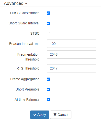
- OBSS Coexistence – automatic channel bandwidth reduction when the air is loaded. When the flag is set, the mode is enabled;
- Short Guard Interval – support for Short Guard interval. Access point transmits data using 400 ns Guard interval (instead of 800 ns) to clients which also support Short GI;
- STBC – Soace-Time Block Coding method dedicated to improve data transmission reliability. When checked, the device transmits one data flow through several antennas. When unchecked, the device does not transmit one data flow through several antennas;
- Beacon Interval, ms – Beacon frame sending period. The frames are sent to detect access points. The parameter takes values from 20 to 2000 ms, by default – 100 ms;
- Fragmentation Threshold – frame fragmentation threshold, bytes. The parameter takes values 256-2346, by default – 2346;
- RTS Threshold – after what quantity of bytes the Request to Send will be sent. Decreasing of the parameter's value might improve access point operation when there are a lot of clients connected. However, decreasing of the parameter's value will reduce general bandwidth of wireless network. The parameter takes values from 0 to 65535, default is 2347;
- Frame Aggregation – enable support for AMPDU/AMSDU;
- Short Preamble – use of the packet short preamble;
- Airtime Fairness – over-the-air radio accessibility feature. When the flag is set, the function is active – the airtime is distributed evenly among users.
"Radio 5 GHz" submenu
In "Radio 5 GHz" submenu you can configure the main parameters of the radio interface of the device operating in the 5 GHz band.
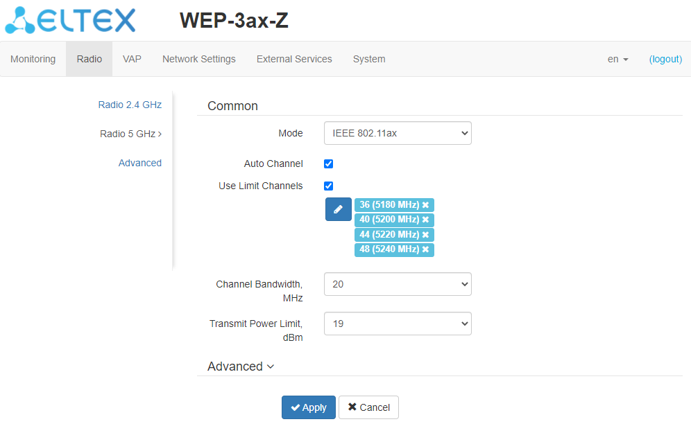
- Mode – select interface operation mode:
- IEEE 802.11ax;
- IEEE 802.11a/n/ac;
- IEEE 802.11a/n/ac/ax.
- Auto Channel – when checked, the device will automatically select the least loaded radio channel for the Wi-Fi interface. Removing the flag opens the access to install the static operation channel;
- Channel – select channel for data transmission;
- Use Limit Channels – when checked, the access point will use a user-defined list of channels to work in automatic channel selection mode. If the "Use Limit Channels" flag is not checked or there are no channels in the list, the access point will select the operation channel from all available channels in the given band. 5 GHz range channels: 36-64, 132-144, 149-165;
- Channel Bandwidth, MHz – channel bandwidth, on which the access point operates. The parameter may take values of 20, 40 and 80 MHz;
- Primary Channel – the parameter can only be changed if the bandwidth of a statically specified channel is equal to 40 MHz. The 40 MHz channel can be considered as consisting of two 20 MHz channels, which border in the frequency range. These two 20 MHz channels are called primary and secondary channels. The primary channel is used by clients who only support 20 MHz channel bandwidth:
- Upper – the primary channel will be the upper 20 MHz channel in the 40 MHz band;
- Lower – the primary channel will be the lower 20 MHz channel in the 40 MHz band.
- Transmit Power Limit, dBm – transmitting Wi-Fi signal power adjustment, dBm. May take values between 10 and 19 dBm.
If the "Use Limit channels" list contains a channel that is not available for selection, it will be marked in grey. In order for the new configuration to be applied to an access point, only available (blue highlighted) channels must be specified in the "Use Limit channels" list.
Example. No settings have been made on the access point yet, Radio 5 GHz is set to 20 MHz "Channel Bandwidth" by default, and channels are specified in the "Use Limit Channels" list: 36, 40, 44, 48.
Suppose the parameter "Channel Bandwidth" is set to 40 MHz. When you change this parameter from 20 MHz to 40 MHz, the following happens:
- the "Primary Channel" parameter becomes available for editing and the default value is "Lower",
- channels 40 and 48 in the "Use Limit Channels" list changes its color from blue to gray.
If you change the "Channel Bandwidth" parameter to 40 MHz and do not remove the "grey" channels from the list, then when you click the "Apply" button in the browser an error will appear – "There are errors in data. Changes was not applied". Accordingly, the access point configuration will not be changed. This is due to the fact that channels in the "Use Limit Channels" list that are highlighted in grey do not fit the definition "Primary channel" = Lower.
In the "Advanced" section, you can configure advanced device’s radio interface parameters.
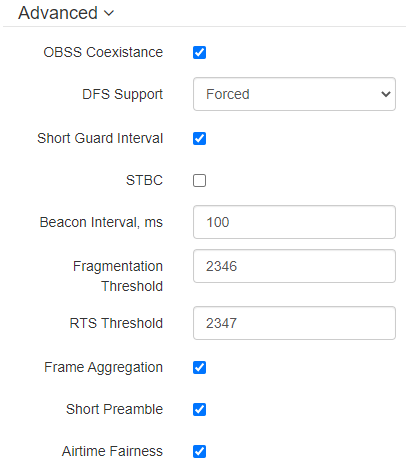
- OBSS Coexistence – automatic channel bandwidth reduction when the air is loaded. When the flag is set, the mode is enabled;
- DFS Support – dynamic frequency selection mechanism. The mechanism demands wireless devices to scan environment and avoid using channels which coincide with radiolocation system's channels at 5 GHz:
- Disabled – the mechanism is disabled. DFS channels are not available for selection;
- Enabled – the mechanism is enabled;
- Forced – the mechanism is disabled. DFS channels are available for selection.
- Short Guard Interval – support for Short Guard interval. Access point transmits data using 400 ns Guard interval (instead of 800 ns) to clients which also support Short GI;
- STBC – Soace-Time Block Coding method dedicated to improve data transmission reliability. When checked, the device transmits one data flow through several antennas. When unchecked, the device does not transmit one data flow through several antennas;
- Beacon Interval, ms – Beacon frame sending period. The frames are sent to detect access points. The parameter takes values from 20 to 2000 ms, by default – 100 ms;
- Fragmentation Threshold – frame fragmentation threshold, bytes. The parameter takes values 256-2346, by default – 2346;
- RTS Threshold – after what quantity of bytes the Request to Send will be sent. Decreasing of the parameter's value might improve access point operation when there are a lot of clients connected. However, decreasing of the parameter's value will reduce general bandwidth of wireless network. The parameter takes values from 0 to 65535, default is 2347;
- Frame Aggregation – enable support for AMPDU/AMSDU;
- Short Preamble – use of the packet short preamble;
- Airtime Fairness – over-the-air radio accessibility feature. When the flag is set, the function is active – the airtime is distributed evenly among users.
"Advanced" submenu
In "Advanced" section, you can configure advanced device’s radio interface parameters.
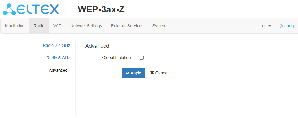
- Global Isolation – when checked, traffic isolation between clients of different VAP and different radio interfaces is enabled.
To apply a new configuration and save setting to non-volatile memory, click "Apply". Click "Cancel" to discard the changes.
"VAP" menu
In "VAP" menu, you can configure virtual Wi-Fi access points (VAP).
"Summary" submenu
"Summary" submenu displays the settings of all VAPs on Radio 2.4 GHz and Radio 5 GHz radio interfaces.
Only the first four VAPs of each radio interface are displayed on the page by default. To see the full list of available VAPs, click the "Show all" button. Click the "Minimize" button to return the number of VAPs in the list to their original state.
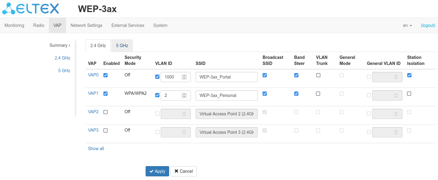
- VAP0..15 – the sequence number of the virtual access point;
- Enabled – when checked, the virtual access point is enabled, otherwise it is disabled;
- Security Mode – the type of data encryption used on the virtual access point;
- VLAN ID – VLAN number from which the tag will be removed when transmitting Wi-Fi traffic to clients connected to this VAP. When traffic flows in the opposite direction, untagged traffic from clients will be tagged with VLAN ID (when VLAN Trunk mode is disabled);
- SSID – virtual wireless network name;
- Broadcast SSID – when checked, SSID broadcasting is on, otherwise it is disabled;
- Band Steer – when this flag is checked, the client's priority connection to the 5 GHz network is active. For this function to work, you need to create a VAP with the same SSID on each radio interface, and activate the "Band Steer" option on them;
- VLAN Trunk – when the flag is set, tagged traffic is transmitted to the subscriber;
- General Mode – when the flag is set, transmission of untagged traffic jointly with tagged traffic is allowed (available when Trunk VLAN mode is enabled);
- General VLAN ID – a tag will be removed from the specified VLAN ID and the traffic of this VLAN will pass to the client without a tag. When traffic passes in the opposite direction, untagged traffic will be tagged with General VLAN ID;
- Station Isolation – when checked, traffic isolation between clients in the same VAP is enabled.
To apply a new configuration and save setting to non-volatile memory, click "Apply". Click "Cancel" to discard the changes.
"VAP" submenu
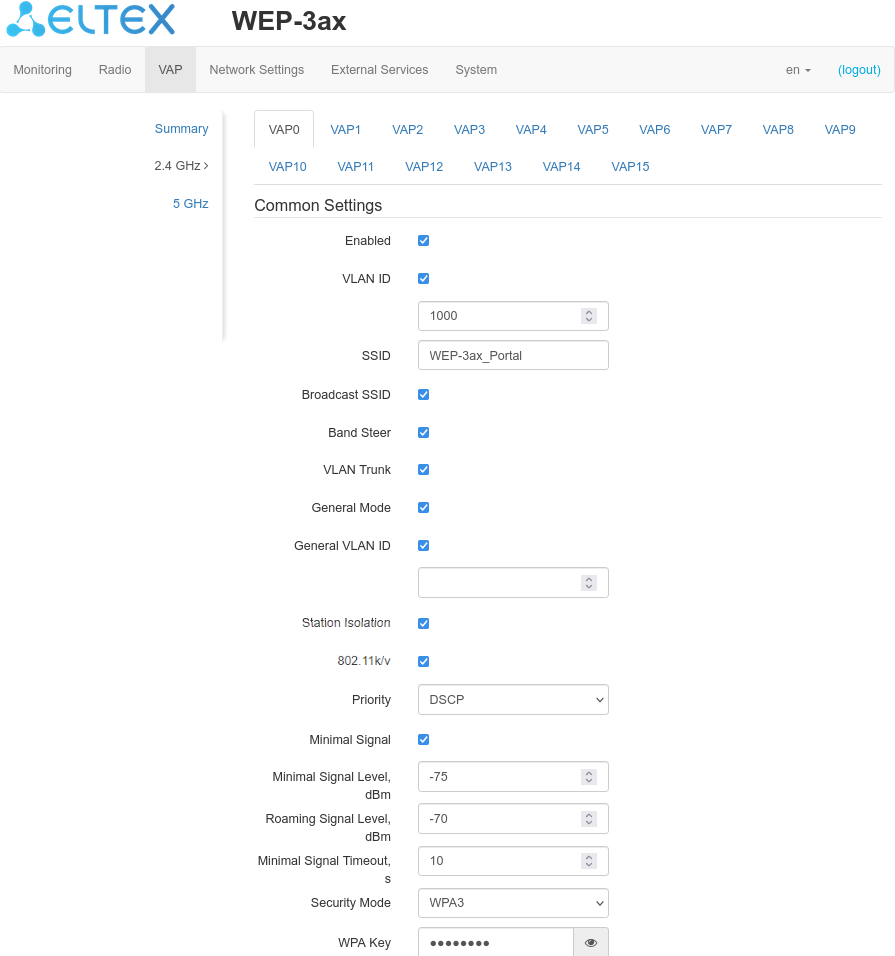
Common Settings
- Enabled – when checked, the virtual access point is enabled, otherwise it is disabled;
- VLAN ID – VLAN number from which the tag will be removed when transmitting Wi-Fi traffic to clients connected to this VAP. When traffic flows in the opposite direction, untagged traffic from clients will be tagged with VLAN ID (when VLAN Trunk mode is disabled);
- SSID – virtual wireless network name;
- Broadcast SSID – when checked, SSID broadcasting is on, otherwise it is disabled;
- Band Steer – when this flag is checked, the client's priority connection to the 5 GHz network is active. For this function to work, you need to create a VAP with the same SSID on each radio interface, and activate the "Band Steer" option on them;
- VLAN Trunk – when the flag is set, tagged traffic is transmitted to the subscriber;
- General Mode – when the flag is set, transmission of untagged traffic jointly with tagged traffic is allowed (available when Trunk VLAN mode is enabled);
- General VLAN ID – a tag will be removed from the specified VLAN ID and the traffic of this VLAN will pass to the client without a tag. When traffic passes in the opposite direction, untagged traffic will be tagged with General VLAN ID;
- Station Isolation – when checked, traffic isolation between clients in the same VAP is enabled;
- 802.11k/v – enable 802.11k/v support on the virtual access point;
- Priority – select prioritization means. Defines the field on the basis of which the traffic transmitted to the radio interface will be distributed in WMM queues:
- DSCP – will analyze the priority from the DSCP field of the IP packet header;
- 802.1p – will analyze the priority from the CoS (Class of Service) field of the tagged packets.
- Minimal Signal – when the flag is checked, the function of disabling the client Wi-Fi equipment at low signal level (Minimal Signal) is enabled. The following parameters must be configured for the functionality to operate:
- Minimal Signal Level – signal level in dBm below which the client equipment is disconnected from the virtual network;
- Roaming Signal Level – roaming sensitivity level in dBm, below which the client equipment is switched to another access point. The parameter must be lower than the Minimal Signal: If Minimal Signal = -75 dBm, then the Roaming Signal Level must be equal or higher than -70 dBm;
- Minimal Signal Timeout – the period of time after which the decision is made to disconnect the client equipment from the virtual network.
- Security Mode – wireless access security mode:
- Off – do not use encryption for data transfer. The access point is available for any subscriber to connect;
- WPA, WPA2, WPA/WPA2, WPA3 – encryption methods, if you select one of the methods, the following setting will be available:
- WPA Key – key/password required to connect to the virtual access point. The length of the key makes from 8 to 63 characters.
- WPA-Enterprise, WPA2-Enterprise, WPA/WPA2-Enterprise – wireless channel encryption mode, in which the client is authorized on the centralized RADIUS server. To configure this security mode, you must specify the parameters of the RADIUS server. If you select one of the encryption modes, the following setting will be available:
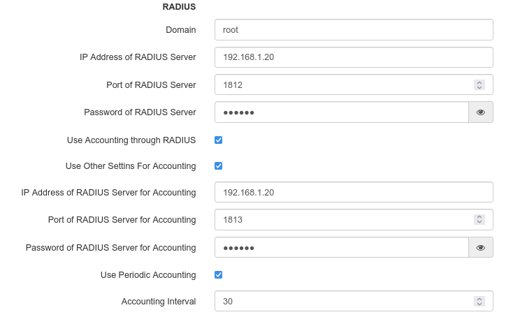
- Domain – user domain;
- IP Address of RADIUS Server – RADIUS server address;
- Port of RADIUS Server – port of the RADIUS server that used for aithentication and authorization;
- Password of RADIUS Server – password for the RADIUS server used for authentication and authorization;
- Use Accounting through RADIUS – when checked, "Accounting" messages will be sent to the RADIUS server;
- Use Other Settings For Accounting:
- IP Address of RADIUS Server for Accounting – address of the RADIUS server, used for accounting;
- Password of RADIUS Server for Accounting – password for the RADIUS server used for accounting.
- Port of RADIUS Server for Accounting – port that will be used to collect accounts on the RADIUS server;
- Use Periodic Accounting – enable periodic sending of "Accounting" messages to the RADIUS server:
- Accounting Interval – interval for sending the "Accounting" messages to the RADIUS server in seconds.
- Use Periodic Accounting – enable periodic sending of "Accounting" messages to the RADIUS server:
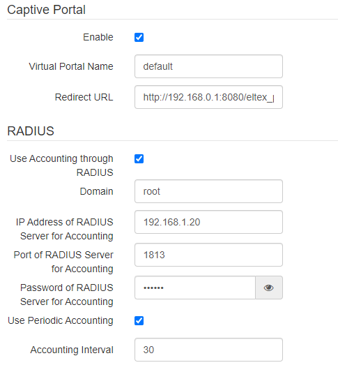
Captive Portal
Under security modes: Off, WPA, WPA2, WPA/WPA2, WPA3 a portal authorization setting is available on the VAP.
- Enable – when checked, authorization of users in the network will be performed via the virtual portal;
- Virtual Portal Name – name of the virtual portal to which the user will be redirected when connecting to the network;
- Redirect URL – the address of the external virtual portal to which the user will be redirected when connecting to the network.
RADIUS
- Use Accounting through RADIUS – when checked, "Accounting" messages will be sent to the RADIUS server;
- Domain – user domain;
- IP Address of RADIUS Server for Accounting – address of the RADIUS server, used for accounting;
- Port of RADIUS Server for Accounting – port that will be used to collect accounts on the RADIUS server;
- Password of RADIUS Server for Accounting – password for the RADIUS server used for accounting;
- Use Periodic Accounting – enable periodic sending of "Accounting" messages to the RADIUS server. You can set the interval for sending messages in the "Accounting Interval":
- Accounting Interval – interval for sending the "Accounting" messages to the RADIUS server in seconds.
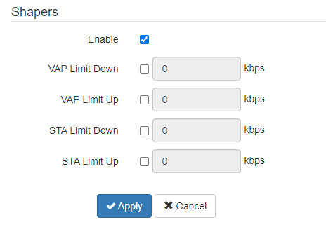
Shapers
- Enable – display configuration field;
- VAP Limit Down – restriction of bandwidth in the direction from the access point to the clients (in total) connected to this VAP, Kbps;
- VAP Limit Up – restriction of bandwidth in the direction from the clients (in total) connected to this VAP, to the access point, Kbps;
- STA Limit Down – restriction of bandwidth in the direction from the access point to the clients (each separately) connected to this VAP, Kbps;
- STA Limit Up – restriction of bandwidth in the direction from the clients (each separately) connected to this VAP, to the access point, Kbps.
To apply a new configuration and save setting to non-volatile memory, click "Apply". Click "Cancel" to discard the changes.
"Network Settings" menu
"System Configuration" submenu
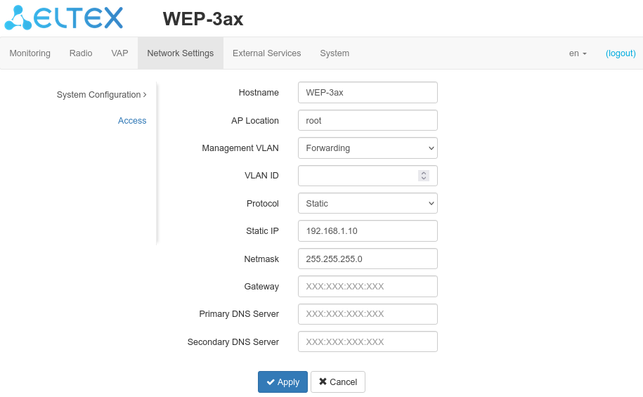
- Hostname – network name of the device, specified by string from 1 to 63 characters; latin uppercase and lowercase letters, numbers, hyphen '-' (hyphen can not be the last character in the name);
- AP Location – domain of the EMS management system tree host where the access point is located;
- Management VLAN:
- Disabled – Management VLAN is not used;
- Terminating – the mode in which the management VLAN is terminated at the access point; in this case, clients connected via the radio interface do not have access to this VLAN;
- Forwarding – the mode in which the management VLAN is also transmitted to the radio interface (with the appropriate VAP configuration).
- VLAN ID – the VLAN ID used to access the device, takes values 1-4094;
- Protocol – select protocol for connection of the device via Ethernet interface to service provider network:
- DHCP – operation mode, when IP address, subnet mask, DNS server address, defualt gateway and other parameters required for operation are obtained from DHCP server automatically;
- Static – operation mode where IP address and all the necessary parameters for WAN interface are assigned statically. If "Static" is selected, the following parameters will be available to set:
- Static IP – device WAN interface IP address in the provider network;
- Netmask – external subnet mask;
- Gateway – address, to which the packet is sent, if the route in routing table is not found for it.
- Primary DNS Server, Secondary DNS Server – IP address of DNS servers. If DNS servers' addresses are not allocated automatically via DHCP, set them manually.
To apply a new configuration and save setting to non-volatile memory, click "Apply". Click "Cancel" to discard the changes.
"Access" submenu
In "Access" submenu, you can configure access to the device via the web interface, Telnet, SSH, NETCONF and SNMP.
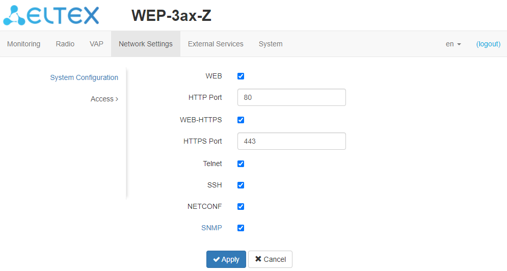
- To enable access to the device via the web interface via HTTP protocol, set the flag next to "WEB". In the window that appears, it is possible to change the HTTP port (by default, 80). The range of acceptable values of ports, in addition to the default, from 1025 to 65535 inclusive;
To enable access to the device via the web interface via HTTPS protocol, set the flag next to "WEB-HTTPS". In the window that appears, it is possible to change the HTTPS port (by default, 443). The range of acceptable values of ports, in addition to the default, from 1025 to 65535 inclusive;
Note that the ports for the HTTP and HTTPS protocols should not have the same value.
- To enable access to the device via Telnet, check the box next to "Telnet";
- To enable access to the device via SSH, check the box next to "SSH";
- To enable access to the device via NETCONF, check the box next to "NETCONF";
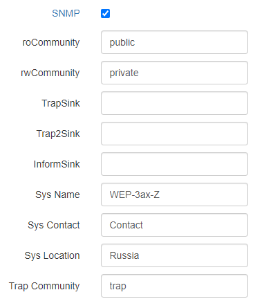
To change the parameters of the access point SNMP agent, it is necessary to check the "SNMP" checkbox and click on the "SNMP" link, a list of parameters available for editing will appear:
- roCommunity – password for parameter reading (common: public);
- rwCommunity – password for parameter writing (common: private);
- TrapSink – IP address or domain name of SNMPv1-trap message recipient in HOST [COMMUNITY [PORT]] format;
- Trap2Sink – IP address or domain name of SNMPv2-trap message recipient in HOST [COMMUNITY [PORT]] format;
- InformSink – IP address or domain name of Inform message recipient in HOST [COMMUNITY [PORT]] format;
- Sys Name – device name;
- Sys Contact – device vendor contact information;
- Sys Location – device location information;
- Trap Community – a password which is contained in traps (by default: trap).
To apply a new configuration and save setting to non-volatile memory, click "Apply". Click "Cancel" to discard the changes.
"External Services" menu
"Captive Portal" submenu
"Captive Portal" submenu is designed to enable and configure the APB service at the access point.
The APB service is used to provide portal roaming of clients between access points connected to the service.
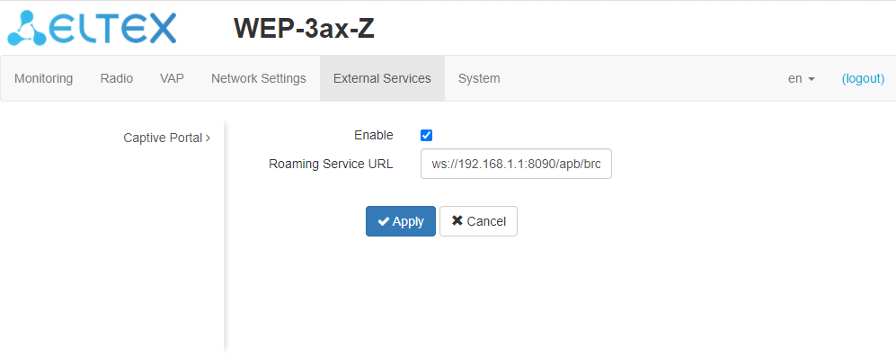
- Enable – when checked, the point will connect to the APB service, the address of which is specified in the "Roaming Service URL" field, to provide portal roaming of clients;
- Roaming Service URL – APB service address to support roaming in the portal authorization mode. Specified as: "ws://<host>:<port>/apb/broadcast".
To apply a new configuration and save setting to non-volatile memory, click "Apply". Click "Cancel" to discard the changes.
"System" menu
In "System" menu you can configure system, time, device access via different protocols, change password and update device firmware.
"Device Firmware Upgrade" submenu
"Device Firmware Upgrade" submenu is intended for upgrading the device's firmware.
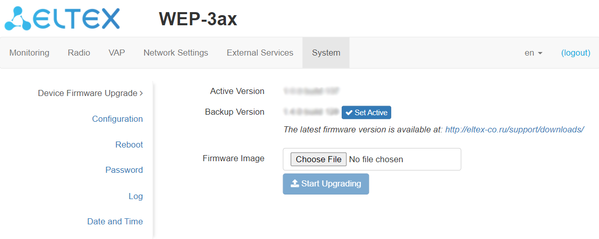
- Active Version – installed firmware version, which is operating at the moment;
- Backup Version – installed firmware version which can be used in case of problems with the current active firmware version;
- Set Active – a button that allows you to make a backup version of the firmware active, this will require a reboot of the device. The active firmware version will not be set as a backup.
Firmware update
Download the firmware file from http://eltex-co.com/support/downloads/ and save it on your computer. To do this, click the "Choose File" button in the Firmware Image field and specify the path to the firmware file in .tar.gz format.
To start the update process, you must click the "Start Upgrading" button. The process may take several minutes (its current status will be shown on the page). The device will be automatically rebooted when the update is completed.
Do not switch off or reboot the device during the firmware update.
"Configuration" submenu
In "Configuration" submenu you can save and update current configuration.
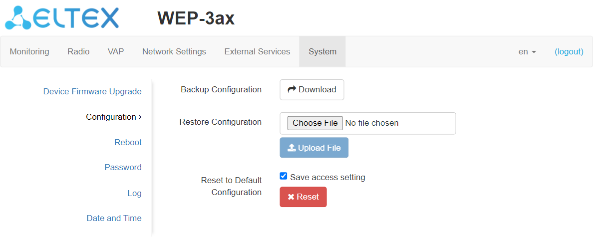
Backup Configuration
To save current device configuration to local computer click on the "Download" button.
Restore Configuration
To download the configuration file saved on the local computer, use the Restore Configuration item. To update the device configuration click the "Choose File" button, specify a file (in .tar.gz format) and click the "Upload File" button. Uploaded configuration will be applied automatically and does not require device reboot.
Reset to Default Configuration
To reset all the settings to default values, click the "Reset" button. If the "Save access setting" flag is activated, then those settings, configurations that are responsible for access to the device (IP address settings, Telnet/SSH/SNMP/Netconf/web access settings) will be saved.
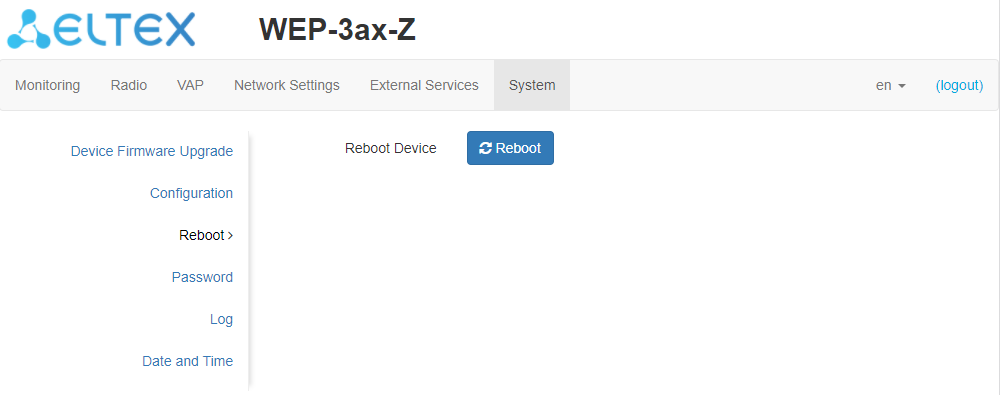
"Reboot" submenu
To reboot the device, click on the "Reboot" button. The device reboot process takes about 1 minute.
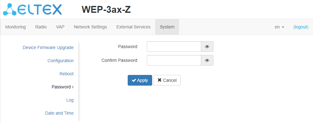
"Password" submenu
When signing into web interface, administrator (default password: password) has the full access to the device: read/write any settings, full device status monitoring.
To change the password, enter the new password first in the "Password" field, then repeat this password in the "Confirm Password" field and click the "Apply" button to save the configuration.
"Log" submenu
The "Log" submenu is designed to configure the output of various kinds of debugging messages of the system in order to detect the causes of problems in the operation of the device.
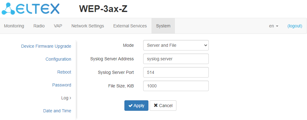
- Mode – Syslog agent operation mode:
- Local File – log information is stored in a local file and is available in the device’s web interface on the "Monitoring/Events" tab;
- Server and File – log information is sent to a remote Syslog server and stored in a local file.
- Syslog Server Address – IP address or domain name of the Syslog server;
- Syslog Server Port – port for incoming Syslog server messages (default: 514, valid values: from 1 to 65535);
- File Size, KiB – maximum size of the log file (valid values: 1-1000 kB).
"Date and Time" submenu
In "Date and Time" submenu, you can set the time manually or using the time synchronization protocol (NTP).
Manual
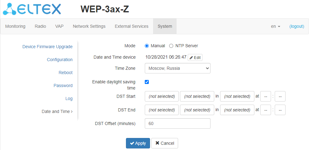
- Date and Time device – date and time set on the device. Click the "Edit" button if the correction is necessary;
- Date, Time – set the current date and time or click the "Set current date and time" button to synchronize with the device;
- Time Zone – allows setting the time zone according to the nearest city for your region from the list;
- Enable daylight saving time – when selected, automatic daylight saving change will be performed automatically within the defined time period:
- DST Start – day and time, when daylight saving time is starting;
- DST End – day and time, when daylight saving time is ending;
- DST Offset (minutes) – time period in minutes, on which time offset is performing.
NTP Server
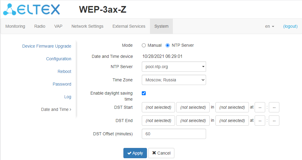
- Date and Time device – date and time set on the device;
- NTP Server – time synchronization server IP address/domain name. You can specify an address or select from an existing list;
- Time Zone – allows setting the time zone according to the nearest city for your region from the list.
To apply a new configuration and store settings into the non-volatile memory, click the "Apply" button. To discard changes click the "Cancel" button.
Device management via the command line
To display the existing settings of a particular configuration section, enter the show-config command.
Press the key combination (English layout) – [Shift + ? ] to get a hint of what value this or that configuration parameter can take.
To get a list of options available for editing in this configuration section, press the Tab key.
To save the settings, enter the save command.
To go back to the previous configuration section, enter the exit command.
Connection to the device
By default, WEP-3ax, WEP-3ax-Z is configured to receive the address via DHCP. If this does not happen, you can connect to the device using the factory IP address.
The default IP-address of the device – 192.168.1.10, subnet mask – 255.255.255.0
Connection to the device is performed via SSH/Telnet:
ssh admin@<IP address of the device>, then enter the password
telnet <IP address of the device>, enter login and password
Network parameters configuration
WEP-3ax(root):/# configure
WEP-3ax(config):/# interface
WEP-3ax(config):/interface# br0
WEP-3ax(config):/interface/br0# common
WEP-3ax(config):/interface/br0/common# static-ip X.X.X.X (where X.X.X.X – WEP-3ax IP address)
WEP-3ax(config):/interface/br0/common# netmask X.X.X.X (where X.X.X.X – Subnet mask)
WEP-3ax(config):/interface/br0/common# dns-server-1 X.X.X.X (where X.X.X.X – IP address of the dns server #1)
WEP-3ax(config):/interface/br0/common# dns-server-2 X.X.X.X (where X.X.X.X – IP address of the dns server #2)
WEP-3ax(config):/interface/br0/common# protocol static-ip (Change operation mode from DHCP to Static-IP)
WEP-3ax(config):/interface/br0/common# save (Save configuration)
Static route adding
WEP-3ax(config):/interface/br0/common# exit
WEP-3ax(config):/interface/br0# exit
WEP-3ax(config):/interface# exit
WEP-3ax(config):/# route
WEP-3ax(config):/route# add default (where default – route name)
WEP-3ax(config):/route# default
WEP-3ax(config):/route/default# destination X.X.X.X (where X.X.X.X – destination host or network IP address, for the default route – 0.0.0.0)
WEP-3ax(config):/route/default# netmask X.X.X.X (where X.X.X.X – destination network mask, for the default route – 0.0.0.0)
WEP-3ax(config):/route/default# gateway X.X.X.X (where X.X.X.X – gateway IP address)
WEP-3ax(config):/route/default# save (Save configuration)
WEP-3ax(root):/# configure
WEP-3ax(config):/# interface
WEP-3ax(config):/interface# br0
WEP-3ax(config):/interface/br0# common
WEP-3ax(config):/interface/br0/common# protocol dhcp
WEP-3ax(config):/interface/br0/common# save (Save changes)
Network parameters configuration using the set-management-vlan-mode utility
Obtain network parameters via DHCP:
WEP-3ax(root):/# set-management-vlan-mode off protocol dhcp
Static parameters:
WEP-3ax(root):/# set-management-vlan-mode off protocol static-ip ip-addr X.X.X.X netmask Y.Y.Y.Y gateway Z.Z.Z.Z (where X.X.X.X - static IP address, Y.Y.Y.Y - subnet mask, Z.Z.Z.Z - gateway)
Obtain network parameters via DHCP:
WEP-3ax(root):/# set-management-vlan-mode terminating vlan-id X protocol dhcp (where X - VLAN ID used for device access. Possible values: 1-4094)
Static parameters:
WEP-3ax(root):/# set-management-vlan-mode terminating vlan-id X protocol static-ip ip-addr X.X.X.X netmask Y.Y.Y.Y gateway Z.Z.Z.Z (where X - VLAN ID used for device access. Possible values: 1-4094, X.X.X.X - static IP address; Y.Y.Y.Y - subnet mask; Z.Z.Z.Z - gateway)
Obtain network parameters via DHCP:
WEP-3ax(root):/# set-management-vlan-mode forwarding vlan-id X protocol dhcp (where X - VLAN ID used for device access. Possible values: 1-4094)
Static parameters:
WEP-3ax(root):/# set-management-vlan-mode forwarding vlan-id X protocol static-ip ip-addr X.X.X.X netmask Y.Y.Y.Y gateway Z.Z.Z.Z (where X - VLAN ID used for device access. Possible values: 1-4094, X.X.X.X - static IP address; Y.Y.Y.Y - subnet mask; Z.Z.Z.Z - gateway)
WEP-3ax(root):/# save (Save configuration)
Virtual Wi-Fi access points (VAP) configuration
When configuring a VAP, remember that the interface names in the 2.4 GHz range start with wlan0, in the 5 GHz range with wlan1.
Table 7 – Commands for configuration of security mode on VAP
Security mode | Command to set the security mode |
|---|---|
Without password | mode off |
WPA | mode WPA |
WPA2 | mode WPA2 |
WPA/WPA2 | mode WPA_WPA2 |
WPA3 | mode WPA3 |
WPA-Enterprise | mode WPA_1X |
WPA2-Enterprise | mode WPA2_1X |
WPA/WPA2-Enterprise | mode WPA_WPA2_1X |
Below are examples of VAP configuration with different security modes for Radio 5 GHz (wlan1).
Configuration of VAP without encryption
WEP-3ax(root):/# configure
WEP-3ax(config):/# interface
WEP-3ax(config):/interface# wlan1-vap0
WEP-3ax(config):/interface/wlan1-vap0# common
WEP-3ax(config):/interface/wlan1-vap0/common# enabled true (Enable virtual access point)
WEP-3ax(config):/interface/wlan1-vap0/common# exit
WEP-3ax(config):/interface/wlan1-vap0# vap
WEP-3ax(config):/interface/wlan1-vap0/vap# ssid 'SSID_WEP-3ax_open' (Change SSID name)
WEP-3ax(config):/interface/wlan1-vap0/vap# ap-security (Transition to the security settings block on the VAP)
WEP-3ax(config):/interface/wlan1-vap0/vap/ap-security# mode off (Encryption off – without password)
WEP-3ax(config):/interface/wlan1-vap0/vap/ap-security# save (Save configuration)
Configuration of VAP with WPA-Personal security mode
WEP-3ax(root):/# configure
WEP-3ax(config):/# interface
WEP-3ax(config):/interface# wlan1-vap0
WEP-3ax(config):/interface/wlan1-vap0# common
WEP-3ax(config):/interface/wlan1-vap0/common# enabled true (Enable virtual access point)
WEP-3ax(config):/interface/wlan1-vap0/common# exit
WEP-3ax(config):/interface/wlan1-vap0# vap
WEP-3ax(config):/interface/wlan1-vap0/vap# ssid 'SSID_WEP-3ax_Wpa2' (Change SSID name)
WEP-3ax(config):/interface/wlan1-vap0/vap# ap-security (Transition to the security settings block on the VAP)
WEP-3ax(config):/interface/wlan1-vap0/vap/ap-security# mode WPA_WPA2 (Encryption mode – WPA/WPA2)
WEP-3ax(config):/interface/wlan1-vap0/vap/ap-security# key-wpa password123 (where password123 – key/password required to connect to the virtual access point. The length of the key must be between 8 and 63 characters)
WEP-3ax(config):/interface/wlan1-vap0/vap/ap-security# save (Save configuration)
Configuration of VAP with Enterprise authorization
WEP-3ax(root):/# configure
WEP-3ax(config):/# interface
WEP-3ax(config):/interface# wlan1-vap0
WEP-3ax(config):/interface/wlan1-vap0# common
WEP-3ax(config):/interface/wlan1-vap0/common# enabled true (Enable virtual acess point)
WEP-3ax(config):/interface/wlan1-vap0/common# exit
WEP-3ax(config):/interface/wlan1-vap0# vap
WEP-3ax(config):/interface/wlan1-vap0/vap# ssid 'SSID_WEP-3ax_enterprise' (Change SSID name)
WEP-3ax(config):/interface/wlan1-vap0/vap# ap-security (Transition to the security settings block on the VAP)
WEP-3ax(config):/interface/wlan1-vap0/vap/ap-security# mode WPA_WPA2_1X (Encryption mode – WPA/WPA2-Enterprise)
WEP-3ax(config):/interface/wlan1-vap0/vap/ap-security# exit
WEP-3ax(config):/interface/wlan1-vap0/vap# radius
WEP-3ax(config):/interface/wlan1-vap0/vap/radius# domain root (where root – User domain)
WEP-3ax(config):/interface/wlan1-vap0/vap/radius# auth-address X.X.X.X (where X.X.X.X –RADIUS server IP address)
WEP-3ax(config):/interface/wlan1-vap0/vap/radius# auth-port X (Where X – RADIUS server port used for authentication and authorization. Default: 1812)
WEP-3ax(config):/interface/wlan1-vap0/vap/radius# auth-password secret (where secret – RADIUS server password used for authentication and authorization)
WEP-3ax(config):/interface/wlan1-vap0/vap/radius# acct-enable true (Enable the sending of "Accounting" messages to the RADIUS server. Default: false)
WEP-3ax(config):/interface/wlan1-vap0/vap/radius# acct-address X.X.X.X (where X.X.X.X – IP address of the RADIUS server used for accounting)
WEP-3ax(config):/interface/wlan1-vap0/vap/radius# acct-password secret (where secret – Password of the RADIUS server used for accounting)
WEP-3ax(config):/interface/wlan1-vap0/vap/radius# acct-periodic true (Enable the periodic sending of "Accounting" messages to the RADIUS server. Default: false)
WEP-3ax(config):/interface/wlan1-vap0/vap/radius# acct-interval 600 (Interval of sending of "Accounting" messages to the RADIUS server)
WEP-3ax(config):/interface/wlan1-vap0/vap/radius# save (Save configuration)
Configuration of VAP with Captive Portal
WEP-3ax(root):/# configure
WEP-3ax(config):/# interface
WEP-3ax(config):/interface# wlan1-vap0
WEP-3ax(config):/interface/wlan1-vap0# common
WEP-3ax(config):/interface/wlan1-vap0/common# enabled true
WEP-3ax(config):/interface/wlan1-vap0/common# exit
WEP-3ax(config):/interface/wlan1-vap0# vap
WEP-3ax(config):/interface/wlan1-vap0/vap# vlan-id X (where X – VLAN-ID on VAP)
WEP-3ax(config):/interface/wlan1-vap0/vap# ap-security (Transition to the security settings block on the VAP)
WEP-3ax(config):/interface/wlan1-vap0/vap/ap-security# mode off (Encryption mode off – Without password)
WEP-3ax(config):/interface/wlan1-vap0/vap/ap-security# exit
WEP-3ax(config):/interface/wlan1-vap0/vap# ssid 'Portal_WEP-3ax' (Change SSID name)
WEP-3ax(config):/interface/wlan1-vap0/vap# captive-portal
WEP-3ax(config):/interface/wlan1-vap0/vap/captive-portal# scenarios
WEP-3ax(config):/interface/wlan1-vap0/vap/captive-portal/scenarios# scenario-redirect
WEP-3ax(config):/interface/wlan1-vap0/vap/captive-portal/scenarios/scenario-redirect# redirect-url http://<IP>:<PORT>/eltex_portal/ (Specify virtual portal URL)
WEP-3ax(config):/interface/wlan1-vap0/vap/captive-portal/scenarios/scenario-redirect# virtual-portal-name default (Specify portal name. Default: default)
WEP-3ax(config):/interface/wlan1-vap0/vap/captive-portal/scenarios/scenario-redirect# exit
WEP-3ax(config):/interface/wlan1-vap0/vap/captive-portal/scenarios# exit
WEP-3ax(config):/interface/wlan1-vap0/vap/captive-portal# enabled true
WEP-3ax(config):/interface/wlan1-vap0/vap/captive-portal# exit
WEP-3ax(config):/interface/wlan1-vap0/vap# radius
WEP-3ax(config):/interface/wlan1-vap0/vap/radius# domain root (where root – User domain)
WEP-3ax(config):/interface/wlan1-vap0/vap/radius# acct-enable true (Enable the sending of "Accounting" messages to the RADIUS server. Default: false)
WEP-3ax(config):/interface/wlan1-vap0/vap/radius# acct-address X.X.X.X (where X.X.X.X – IP address of the RADIUS server used for accounting)
WEP-3ax(config):/interface/wlan1-vap0/vap/radius# acct-password secret (where secret – Password for RADIUS server used for accounting)
WEP-3ax(config):/interface/wlan1-vap0/vap/radius# acct-periodic true (Enable the periodic sending of "Accounting" messages to the RADIUS server Default: false)
WEP-3ax(config):/interface/wlan1-vap0/vap/radius# acct-interval 600 (Interval of sending of "Accounting" messages to the RADIUS server)
WEP-3ax(config):/interface/wlan1-vap0/vap/radius# save (Save configuration)
Advanced VAP settings
WEP-3ax(config):/interface/wlan1-vap0/vap# vlan-id X (where X – VLAN-ID number on VAP)
WEP-3ax(config):/interface/wlan1-vap0/vap# priority-by-dscp false (Priority analysis from the CoS (Class of Service) field of tagged packets. Default value: true. In this case the priority from the DSCP field of the IP packet header is analyzed)
WEP-3ax(config):/interface/wlan1-vap0/vap# vlan-trunk true (Enable VLAN Trunk on VAP. To disable, enter false)
WEP-3ax(config):/interface/wlan1-vap0/vap# general-vlan-mode true (Enabling General VLAN on SSID. To disable, enter false)
WEP-3ax(config):/interface/wlan1-vap0/vap# general-vlan-id X (where X – General VLAN number)
WEP-3ax(config):/interface/wlan1-vap0/vap# hidden true (Enable hidden SSID. To disable, enter false)
WEP-3ax(config):/interface/wlan1-vap0/vap# band-steer-mode true (Enable Band Steer mode. To disable, enter false)
WEP-3ax(config):/interface/wlan1-vap0/vap# station-isolation true (Enable traffic isolation between clients within a single VAP. To disable, enter false)
WEP-3ax(config):/interface/wlan1-vap0/vap# check-signal-enable true (Enable the use of Minimal Signal functionality. To disable enter false)
WEP-3ax(config):/interface/wlan1-vap0/vap# min-signal -X (where X – RSSI threshold value, when reached, the point will disconnect the client from the VAP. The parameter can take values from -100 to -1)
WEP-3ax(config):/interface/wlan1-vap0/vap# check-signal-timeout X (where X – time period in seconds, after which the decision is made to disconnect the client equipment from the virtual network)
WEP-3ax(config):/interface/wlan1-vap0/vap# roaming-signal -X (where X – RSSI threshold value, when reached, the client equipment is switched to another access point. The parameter can take values from -100 to -1 The roaming-signal parameter must be lower than min-signal: if min-signal = -75 dBm, then roaming-signal must be equal or higher than -70 dBm).
WEP-3ax(config):/interface/wlan1-vap0/vap# save (Save configuration)
Configuring the shaper in the direction from the clients (each individually) connected to this VAP to the AP:
WEP-3ax(config):/interface/wlan1-vap0/vap# shaper-per-sta-rx
WEP-3ax(config):/interface/wlan1-vap0/vap/shaper-per-sta-rx# value X (where X – maximum rate in Kbps)
WEP-3ax(config):/interface/wlan1-vap0/vap/shaper-per-sta-rx# mode kbps (Enable shaper. To disable enter off)
WEP-3ax(config):/interface/wlan1-vap0/vap/shaper-per-sta-rx# exit
WEP-3ax(config):/interface/wlan1-vap0/vap# save (Save configuration)
Configuring the shaper in the direction from the AP to the clients (each individually) connected to this VAP:
WEP-3ax(config):/interface/wlan1-vap0/vap# shaper-per-sta-tx
WEP-3ax(config):/interface/wlan1-vap0/vap/shaper-per-sta-tx# value X (where X – maximum rate in Kbps)
WEP-3ax(config):/interface/wlan1-vap0/vap/shaper-per-sta-tx# mode kbps (Enable shaper. To disable enter off)
WEP-3ax(config):/interface/wlan1-vap0/vap/shaper-per-sta-tx# exit
WEP-3ax(config):/interface/wlan1-vap0/vap# save (Save configuration)
Configuring the shaper in the direction from the clients (all) connected to this VAP to the AP:
WEP-3ax(config):/interface/wlan1-vap0/vap# shaper-per-vap-rx
WEP-3ax(config):/interface/wlan1-vap0/vap/shaper-per-vap-rx# value X (where X – maximum rate in Kbps)
WEP-3ax(config):/interface/wlan1-vap0/vap/shaper-per-vap-rx# mode kbps (Enable shaper. To disable enter off)
WEP-3ax(config):/interface/wlan1-vap0/vap/shaper-per-vap-rx# exit
WEP-3ax(config):/interface/wlan1-vap0/vap# save (Save configuration)
Configuring the shaper in the direction from the AP to the clients (all) connected to this VAP:
WEP-3ax(config):/interface/wlan1-vap0/vap# shaper-per-vap-tx
WEP-3ax(config):/interface/wlan1-vap0/vap/shaper-per-vap-tx# value X (where X – maximum rate in Kbps)
WEP-3ax(config):/interface/wlan1-vap0/vap/shaper-per-vap-tx# mode kbps (Enable shaper. To disable enter off)
WEP-3ax(config):/interface/wlan1-vap0/vap/shaper-per-vap-tx# exit
WEP-3ax(config):/interface/wlan1-vap0/vap# save (Save configuration)
802.11r configuration
This type of roaming is only available for client devices that support 802.11r.
802.11r roaming is only possible between VAPs with security modes: WPA2 Personal and WPA2 Enterprise.
For instructions on configuring a VAP with different security modes, see section Configuration of VAP with WPA-Personal security mode.
Each VAP on access points should be configured individually, such as AP1(wlan1)↔AP2(wlan1), AP1(wlan0)↔AP2(wlan0), AP1(wlan1)↔AP3(wlan1), etc.
Below is an example of how to configure 802.11r on two access points: AP1 and AP2.
WEP-3ax(config):/interface/wlan1-vap0/vap/ft-config# enabled false
WEP-3ax(config):/interface/wlan1-vap0/vap/ft-config# r1-key-holder-id E8:28:C1:FC:D6:80 (VAP MAC address. Displayed in the ifconfig command output)
WEP-3ax(config):/interface/wlan1-vap0/vap/ft-config# r0-key-holder-id 12345 (Unique key for the given VAP, for example, a serial number)
WEP-3ax(config):/interface/wlan1-vap0/vap/ft-config# mobility-domain 100 (The domain should be same on the neighboring VAP)
WEP-3ax(config):/interface/wlan1-vap0/vap/ft-config# mac
WEP-3ax(config):/interface/wlan1-vap0/vap/ft-config/mac# add E4:5A:D4:E2:C4:B0 (VAP interface MAC address of the neighboring access point - AP2)
WEP-3ax(config):/interface/wlan1-vap0/vap/ft-config/mac# E4:5A:D4:E2:C4:B0
WEP-3ax(config):/interface/wlan1-vap0/vap/ft-config/mac/E4:5A:D4:E2:C4:B0# r0-kh-id 23456 (Unique key for the counter VAP of the AP2 access point - r0-key-holder-id)
WEP-3ax(config):/interface/wlan1-vap0/vap/ft-config/mac/E4:5A:D4:E2:C4:B0# r1-kh-id E4:5A:D4:E2:C4:B0 (MAC address of the neighboring VAP on AP2)
WEP-3ax(config):/interface/wlan1-vap0/vap/ft-config/mac/E4:5A:D4:E2:C4:B0# r0-kh-key 0102030405060708 (Random key. Must not match r1-kh-key of AP1, but r1-kh-key of the neighboring AP2)
WEP-3ax(config):/interface/wlan1-vap0/vap/ft-config/mac/E4:5A:D4:E2:C4:B0# r1-kh-key 0001020304050607 (Random key. Must not match r0-kh-key of AP1, but r0-kh-key of the neighboring AP2)
WEP-3ax(config):/interface/wlan1-vap0/vap/ft-config/mac/E4:5A:D4:E2:C4:B0# exit
WEP-3ax(config):/interface/wlan1-vap0/vap/ft-config/mac# exit
WEP-3ax(config):/interface/wlan1-vap0/vap/ft-config# enabled true (Enable access point operation using the 802.11r protocol)
WEP-3ax(config):/interface/wlan1-vap0/vap/ft-config# save (Save configuration)
WEP-3ax(config):/interface/wlan1-vap0/vap/ft-config# enabled false
WEP-3ax(config):/interface/wlan1-vap0/vap/ft-config# r1-key-holder-id E4:5A:D4:E2:C4:B0 (VAP MAC address. Displayed in the ifconfig command output)
WEP-3ax(config):/interface/wlan1-vap0/vap/ft-config# r0-key-holder-id 23456 (Unique key for the given VAP, for example, a serial number)
WEP-3ax(config):/interface/wlan1-vap0/vap/ft-config# mobility-domain 100 (The domain should be same on the neighboring VAP)
WEP-3ax(config):/interface/wlan1-vap0/vap/ft-config# mac
WEP-3ax(config):/interface/wlan1-vap0/vap/ft-config/mac# add E8:28:C1:FC:D6:80 (VAP interface MAC address of the neighboring access point - AP1)
WEP-3ax(config):/interface/wlan1-vap0/vap/ft-config/mac# E8:28:C1:FC:D6:80
WEP-3ax(config):/interface/wlan1-vap0/vap/ft-config/mac/E8:28:C1:FC:D6:80# r0-kh-id 12345 (Unique key for the neighboring VAP of the AP1 access point - r0-key-holder-id)
WEP-3ax(config):/interface/wlan1-vap0/vap/ft-config/mac/E8:28:C1:FC:D6:80# r1-kh-id E8:28:C1:FC:D6:80 (MAC address of the neighboring VAP of AP1)
WEP-3ax(config):/interface/wlan1-vap0/vap/ft-config/mac/E8:28:C1:FC:D6:80# r0-kh-key 0001020304050607 (Random key. Must not match r1-kh-key of AP2, but r1-kh-key of the neighboring AP1)
WEP-3ax(config):/interface/wlan1-vap0/vap/ft-config/mac/E8:28:C1:FC:D6:80# r1-kh-key 0102030405060708 (Random key. Must not match r0-kh-key of AP2, but r0-kh-key of the neighboring AP1)
WEP-3ax(config):/interface/wlan1-vap0/vap/ft-config/mac/E8:28:C1:FC:D6:80# exit
WEP-3ax(config):/interface/wlan1-vap0/vap/ft-config/mac# exit
WEP-3ax(config):/interface/wlan1-vap0/vap/ft-config# enabled true (Enable access point operation using the 802.11r protocol)
WEP-3ax(config):/interface/wlan1-vap0/vap/ft-config# save (Save configuration)
802.11r configuration via AirTune
The feature is supported starting from WEP-3ax/WEP-3ax-Z 1.6.0 firmware version, AirTune version – 1.4.0.
For 802.11r auto configuration on the access point via AirTune enable 802.11r functionality and interaction with the AirTune.
Below is an example of how to configure 802.11r via AirTune.
WEP-3ax(config):/interface/wlan1-vap0/vap/ft-config# enabled true (Enable access point operation using the 802.11r protocol)
WEP-3ax(config):/interface/wlan1-vap0/vap/ft-config# exit
WEP-3ax(config):/interface/wlan1-vap0/vap# exit
WEP-3ax(config):/interface# exit
WEP-3ax(config):/# airtune
WEP-3ax(config):/airtune# airtune_service_url ws://192.168.1.20:8099/apb/rrm (where 192.168.1.20 is an IP address of a server, on which the AirTune is installed)
WEP-3ax(config):/airtune# enabled true (Enable interaction with the AirTune service)
WEP-3ax(config):/airtune# save (Save configuration)
AirTune service configuration is described in the SoftWLC controller documentation.
802.11k configuration
802.11k roaming can be organized between any networks (open/encrypted). If the access point is configured to work with the 802.11k protocol, then, when the client connects, the access point sends a list of "friendly" access points to which the client can switch while roaming. The list contains information about the MAC addresses of access points and the channels on which they operate.
Using 802.11k reduces the time it takes the client to find another network when roaming because the client does not have to scan for channels where there are no target access points available for switching.
This type of roaming is only available for client devices that support 802.11k.
Below is an example of how to configure 802.11k on an access point – making a list of "friendly" access points.
WEP-3ax(config):/interface/wlan1-vap0/vap/w80211kv-config# enabled false
WEP-3ax(config):/interface/wlan1-vap0/vap/w80211kv-config# mac
WEP-3ax(config):/interface/wlan1-vap0/vap/w80211kv-config/mac# add E8:28:C1:FC:D6:90 (where E8:28:C1:FC:D6:90 - MAC address of the "friendly" access point)
WEP-3ax(config):/interface/wlan1-vap0/vap/w80211kv-config/mac# E8:28:C1:FC:D6:90
WEP-3ax(config):/interface/wlan1-vap0/vap/w80211kv-config/mac/E8:28:C1:FC:D6:90# channel 132 (where 132 - channel, on which the access point with E8:28:C1:FC:D6:90 MAC address is operating)
WEP-3ax(config):/interface/wlan1-vap0/vap/w80211kv-config/mac/E8:28:C1:FC:D6:90# exit
WEP-3ax(config):/interface/wlan1-vap0/vap/w80211kv-config/mac# add E8:28:C1:FC:D6:70 (where E8:28:C1:FC:D6:70 - MAC address of the "friendly" access point)
WEP-3ax(config):/interface/wlan1-vap0/vap/w80211kv-config/mac# E8:28:C1:FC:D6:70
WEP-3ax(config):/interface/wlan1-vap0/vap/w80211kv-config/mac/E8:28:C1:FC:D6:70# channel 36 (where 36 - channel, on which the access point with E8:28:C1:FC:D6:70 MAC address is operating)
WEP-3ax(config):/interface/wlan1-vap0/vap/w80211kv-config/mac/E8:28:C1:FC:D6:70# exit
WEP-3ax(config):/interface/wlan1-vap0/vap/w80211kv-config/mac# exit
WEP-3ax(config):/interface/wlan1-vap0/vap/w80211kv-config# enabled true (Enable access point operation using the 802.11k protocol)
WEP-3ax(config):/interface/wlan1-vap0/vap/w80211kv-config# save (Save configuration)
802.11k configuration via AirTune
The feature is supported starting from WEP-3ax/WEP-3ax-Z 1.6.0 firmware version, AirTune version – 1.4.0.
For 802.11k auto configuration on the access point via AirTune enable 802.11r functionality on SSID and interaction with the AirTune.
Below is an example of how to configure 802.11k via AirTune.
WEP-3ax(config):/interface/wlan1-vap1/vap/w80211kv-config# enabled true (Enable access point operation using the 802.11k protocol)
WEP-3ax(config):/interface/wlan1-vap1/vap/w80211kv-config# exit
WEP-3ax(config):/interface/wlan1-vap1/vap# exit
WEP-3ax(config):/interface/wlan1-vap1# exit
WEP-3ax(config):/interface# exit
WEP-3ax(config):/# airtune
WEP-3ax(config):/airtune# airtune_service_url ws://192.168.1.20:8099/apb/rrm (where 192.168.1.20 is an IP address of a server, on which the AirTune is installed)
WEP-3ax(config):/airtune# enabled true (Enable interaction with the AirTune service)
WEP-3ax(config):/airtune# save (Save configuration)
802.11v configuration
802.11v roaming can be organized between any networks (open/encrypted). If an access point is configured to work with 802.11v, then during its operation the device sends a special packet (BSS Transition) to the client side recommending that the client roams. Whether or not the client device will follow the access point's recommendation is impossible to guarantee, because the decision to switch to another access point is ultimately made by the client side. In conjunction with the 802.11k standard, in a message with a recommendation to switch the client is also sent a list of recommended roaming access points, indicating on what channel each point works and what standard (IEEE 802.11n/ac/ax). Then the client analyzes the air and depending on the signal level, channel load, the configuration of the neighboring access point makes a decision.
This type of roaming is only available for client devices that support 802.11v.
wl -i wlan1-vap4 wnm_bsstrans_req 7 150 84:ab:1a:c6:db:17 0 0 (sending a roaming recommendation message to a client with MAC address 84:ab:1a:c6:db:17 connected to wlan1-vap4. If the client does not switch to another access point within 15 seconds of sending this message, the access point will forcibly disconnect the client device from the wireless network)
wl -i wlan1 wnm_bsstrans_req 3 150 84:ab:1a:c6:db:17 5 0 (sending a roaming recommendation message to a client with MAC address 84:ab:1a:c6:db:17, connected to wlan1-vap0. Sending a message without forcing the client device to disconnect from the wireless network)
Radio configuration
In Radio, automatic selection of the operating channel is used by default. To set the channel manually or to change the power, use the following commands:
WEP-3ax(root):/# configure
WEP-3ax(config):/# interface
WEP-3ax(config):/interface# wlan0
WEP-3ax(config):/interface/wlan0# wlan
WEP-3ax(config):/interface/wlan0/wlan# radio
WEP-3ax(config):/interface/wlan0/wlan/radio# channel X (where X – the number of the static channel on which the point will operate)
WEP-3ax(config):/interface/wlan0/wlan/radio# auto-channel false (Disable automatic channel selection functionality. To enable enter true)
WEP-3ax(config):/interface/wlan0/wlan/radio# use-limit-channels false (Disable Use Limit Channels. To enable enter true)
WEP-3ax(config):/interface/wlan0/wlan/radio# bandwidth X (where X – channel bandwidth)
WEP-3ax(config):/interface/wlan0/wlan/radio# tx-power X (where X – Power level in dBm. The parameter may take values: for Radio 2.4 GHz (wlan0): 6-16 dBm; for Radio 5 GHz (wlan1): 10-19 dBm)
WEP-3ax(config):/interface/wlan0/wlan/radio# save (Save configuration)
Available channels lists
The following channels are available to be selected for Radio 2.4 GHz:
- with 20 MHz channel width: 1, 2, 3, 4, 5, 6, 7, 8, 9, 10, 11, 12, 13.
- with 40 MHz channel width:
- if "control-sideband" = lower: 1, 2, 3, 4, 5, 6, 7, 8, 9.
- if "control-sideband" = upper: 5, 6, 7, 8, 9, 10, 11, 12, 13.
The following channels are available to be selected for Radio 5 GHz:
- with 20 MHz channel width: 36, 40, 44, 48, 52, 56, 60, 64, 132, 136, 140, 144, 149, 153, 157, 161, 165.
- with 40 MHz channel width:
- if "control-sideband" = lower: 36, 44, 52, 60, 132, 140, 149, 157.
- if "control-sideband" = upper: 40, 48, 56, 64, 136, 144, 153, 161.
- with 80 MHz channel width: 36, 40, 44, 48, 52, 56, 60, 64, 132, 136, 140, 144, 149, 153, 157, 161.
Advanced Radio settings
WEP-3ax(config):/interface/wlan0/wlan/radio# work-mode X (where X – radio interface operation mode according to the IEEE 802.11 standard. Possible values: for Radio 2.4 GHz (wlan0): bgn, bgnax, ax; for Radio 5 GHz (wlan1): anac, anacax, ax)
WEP-3ax(config):/interface/wlan0/wlan/radio# use-limit-channels true (Enable the use of a limited list of channels in the auto channel selection operation. To disable enter false)
WEP-3ax(config):/interface/wlan0/wlan/radio# limit-channels '1 6 11' (where 1 6 11 – channels of the band in which the configurable radio interface can operate)
WEP-3ax(config):/interface/wlan0/wlan/radio# control-sideband lower (Parameter may take the following values: lower, upper. Default is lower)
WEP-3ax(config):/interface/wlan0/wlan/radio# sgi true (Enable the use of a short guard interval for data transfer – 400 ns, instead of 800 ns. To disable, enter false)
WEP-3ax(config):/interface/wlan0/wlan/radio# stbc true (Enabling the Spatial-Time Block Coding (STBC) method, aimed at improving the reliability of data transmission. To disable, enter false)
WEP-3ax(config):/interface/wlan0/wlan/radio# aggregation true (Enabling aggregation on Radio – support for AMPDU/AMSDU. To disable, enter false)
WEP-3ax(config):/interface/wlan0/wlan/radio# short-preamble true (Enabling the short packet preamble. To disable, enter false)
WEP-3ax(config):/interface/wlan0/wlan/radio# wmm true (Enabling the support for WMM (Wi-Fi Multimedia) To disable, enter false)
Only Radio 5 GHz (wlan1) is configured
WEP-3ax(config):/interface/wlan1/wlan/radio# dfs X (where X – DFS mechanism operation mode. May take values: forced – mechanism is disabled, DFS channels are available for selection; auto – mechanism is enabled; disabled – mechanism is disabled, DFS channels are unavailable for selection)
WEP-3ax(config):/interface/wlan0/wlan/radio# obss-coex true (Enable automatic change of channel width from 40 MHz to 20 MHz when the radio is busy. To disable, enter false)
System settings
Device firmware update
WEP-3ax(root):/# firmware upload tftp <tftp server ip address> <Firmware file name> (Example: firmware upload tftp 192.168.1.100 WEP-3ax-1.6.0_build_105.tar.gz)
WEP-3ax(root):/# firmware upgrade
WEP-3ax(root):/# firmware upload http <frimware file URL> (Example: firmware upload http http://192.168.1.100:8080/files/WEP-3ax-1.6.0_build_105.tar.gz)
WEP-3ax(root):/# firmware upgrade
Device configuration management
WEP-3ax(root):/# manage-config upload tftp <tftp server ip address> <Configuration file name> (Example: manage-config upload tftp 192.168.1.100 config.json)
WEP-3ax(root):/# manage-config apply (Apply configuration on access point)
Device reboot
Setting the date and time
WEP-3ax(root):/# configure
WEP-3ax(config):/# date-time
WEP-3ax(config):/date-time# mode ntp (Enable NTP operation mode)
WEP-3ax(config):/date-time# ntp
WEP-3ax(config):/date-time/ntp# server <NTP server IP address> (Set NTP server)
WEP-3ax(config):/date-time/ntp# exit
WEP-3ax(config):/date-time# common
WEP-3ax(config):/date-time/common# timezone 'Asia/Novosibirsk (Novosibirsk)' (Set timezone)
WEP-3ax(config):/date-time/common# save (Save configuration)
Advanced system settings
WEP-3ax(root):/# configure
WEP-3ax(config):/# system
WEP-3ax(config):/system# global-station-isolation true (Enable global isolation of traffic between clients of different VAPs and different radio interfaces. To disable enter false)
WEP-3ax(config):/system# save (Save configuration)
WEP-3ax(root):/# configure
WEP-3ax(config):/# system
WEP-3ax(config):/system# hostname WEP-3ax_room2 (where WEP-3ax_room2 is the new hostname. The parameter can contain from 1 to 63 characters: Latin uppercase and lowercase letters, numbers, hyphen "-" (the hyphen cannot be the last character in the name). Default: WEP-3ax)
WEP-3ax(config):/system# save (Save configuration)
WEP-3ax(root):/# configure
WEP-3ax(config):/# system
WEP-3ax(config):/system# ap-location ap.test.root (where ap.test.root is the domain of the device tree node of the EMS management system in which the access point is located. Default: root)
WEP-3ax(config):/system# save (Save configuration)
WEP-3ax(root):/# configure
WEP-3ax(config):/# authentication
WEP-3ax(config):/authentication# admin-password newpassword (where newpassword is the new password to log in to the access point. Default: password)
WEP-3ax(config):/authentication# save (Save configuration)
APB service configuration
The APB service is used to provide portal roaming of clients between access points connected to the service.
WEP-3ax(root):/# configure
WEP-3ax(config):/# captive-portal
WEP-3ax(config):/captive-portal# apbd
WEP-3ax(config):/captive-portal/apbd# roam_service_url <APB service address> (Example: roam_service_url ws://192.168.1.100:8090/apb/broadcast)
WEP-3ax(config):/captive-portal/apbd# enabled true (Enable APB service. To disable enter false)
WEP-3ax(config):/captive-portal/apbd# save (Save configuration)
Monitoring
Wi-Fi Clients
WEP-3ax(root):/# monitoring associated-clients
 index                    | 0
 hw-addr                  | ac:c4:13:1c:aa:aa
 hw-addr                  | 62:33:e6:73:bf:ec
 authenticated            | yes
 associated               | yes
 authorized               | yes
 ip-addr                  | 192.168.40.248
 hostname                 | Pixel-6
 identity                 | ivanov.ivan
 domain                   | enterprise.service.root
 rssi-1                   | -64
 rssi-2                   | -66
 rssi-3                   | 0
 rssi-4                   | 0
 noise-1                  | -94
 noise-2                  | -95
 noise-3                  | 0
 noise-4                  | 0
 snr-1                    | 30
 snr-2                    | 29
 snr-3                    | 0
 snr-4                    | 0
 tx-rate                  | HE NSS2-MCS11 2xLTF GI 0.8us 286.8
 rx-rate                  | HE NSS2-MCS9 2xLTF GI 0.8us 229.4
 actual-tx-rate           | 5
 actual-rx-rate           | 4
 tx-fails                 | 1
 tx-retry-count           | 0
 rx-retry-count           | 328
 tx-bw                    | 20
 rx-bw                    | 20
 tx-period-retry          | 0
 link-capacity            | 100%
 link-quality             | 100%
 link-quality-common      | 100%
 uptime                   | 00:13:46
 interface                | wlan1-vap2
 ssid                     | Eltex-Test
 using-802.11r            | yes
 using-802.11k            | no
 using-802.11v            | no
 wireless-mode            | ax
 name                     | wlan1-vap2:sta-0

  Rate                  Transmitted            Received
---------------------------------------------------------------------
 Total Packets:       | 50807                | 2527                 |
 TX success:          | 100                  |                      |
 Total Bytes:         | 20608509             | 491365               |
 Data Packets:        | 50803                | 2522                 |
 Data Bytes:          | 20608377             | 490906               |
 Mgmt Packets:        | 4                    | 5                    |
 Mgmt Bytes:          | 132                  | 459                  |
 Dropped Packets:     | 0                    | 772                  |
 Dropped Bytes:       | 0                    | 18495                |
 Lost Packets:        | 1                    |                      |
---------------------------------------------------------------------

 Rate                  Transmitted            Received
---------------------------------------------------------------------
 ofdm6                | 0              |   0%|            829 |  35%|
 he-nss1-mcs0         | 0              |   0%|              1 |   0%|
 he-nss1-mcs8         | 0              |   0%|              7 |   0%|
 he-nss1-mcs11        | 0              |   0%|              2 |   0%|
 he-nss2-mcs0         | 0              |   0%|              1 |   0%|
 he-nss2-mcs1         | 0              |   0%|              1 |   0%|
 he-nss2-mcs2         | 0              |   0%|              4 |   0%|
 he-nss2-mcs3         | 0              |   0%|             12 |   0%|
 he-nss2-mcs4         | 0              |   0%|            161 |   6%|
 he-nss2-mcs5         | 0              |   0%|             92 |   3%|
 he-nss2-mcs6         | 19             |   0%|            182 |   7%|
 he-nss2-mcs7         | 165            |   1%|            196 |   8%|
 he-nss2-mcs8         | 228            |   2%|            213 |   9%|
 he-nss2-mcs9         | 553            |   4%|            227 |   9%|
 he-nss2-mcs10        | 92             |   0%|            254 |  10%|
 he-nss2-mcs11        | 10335          |  90%|            176 |   7%|
---------------------------------------------------------------------
Device information
WEP-3ax(root):/# monitoring information
   system-time: 09:19:58 22.03.2022
   uptime: 13 d 00:51:28
   software-version: 1.6.0 build 105
   uboot-version: 1.6.0 build 105
   secondary-software-version: 1.6.0 build 99
   boot-version: 1.4.1 build 6
   memory-usage: 36
   memory-free: 638
   memory-used: 368
   memory-total: 1006
   cpu: 0.18
   is-default-config: false
   board-type: WEP-3ax
   hw-platform: WEP-3ax
   factory-mac: CC:9D:A2:xx:xx:xx
   factory-serial-number: WP42001953
   hw-revision: 2v2
   tunnel-ip: 10.24.201.148
   last-reboot-reason: firmware update
Network information
WEP-3ax(root):/# monitoring wan-status
   interface: br0
   protocol: dhcp
   ip-address: 192.168.1.15
   mac: e8:28:c1:xx:xx:xx
   mask: 255.255.255.0
   gateway: 192.168.1.1
   DNS-1: 192.168.1.253
   DNS-2: 172.16.7.40
   rx-bytes: 82542744
   rx-packets: 1119782
   tx-bytes: 2281191
   tx-packets: 8853
WEP-3ax(root):/# monitoring ethernet
   link: up
   speed: 1000
   duplex: enabled
   rx-bytes: 82842279
   rx-packets: 1124216
   tx-bytes: 2283061
   tx-packets: 8875
WEP-3ax(root):/# monitoring arp
#        ip                mac
--------------------------------------------
0        192.168.1.1       02:00:48:xx:xx:xx
1        192.168.1.151     2c:fd:a1:xx:xx:xx
WEP-3ax(root):/# monitoring route
Destination       Gateway           Mask              Flags      Interface
--------------------------------------------------------------------------
0.0.0.0           192.168.1.1      0.0.0.0            UG         br0
192.168.1.0       0.0.0.0          255.255.255.0      U          br0
Wireless interfaces
WEP-3ax(root):/# monitoring radio
   wlan0:
      name: wlan0
      hwaddr: CC:9D:A2:xx:xx:xx
      status: on
      channel: 1
      bandwidth: 20
      frequency: 2412
      power: 16.0
      mode: bgnax
   wlan1:
      hwaddr: CC:9D:A2:xx:xx:xx
      status: on
      channel: 36
      bandwidth: 20
      frequency: 5180
      power: 19.0
      mode: anacax
Event log
WEP-3ax(root):/# monitoring events
Feb 25 05:00:19 WEP-3ax syslog.info syslogd: started: BusyBox v1.30.1

Feb 25 05:00:20 WEP-3ax daemon.info networkd[907]: Networkd started

Feb 25 05:00:26 WEP-3ax daemon.info networkd[907]: DHCP-client: Interface br0 obtained lease on 192.168.1.15.

Feb 25 05:14:59 WEP-3ax auth.info login[1738]: root login on 'pts/0'

Feb 25 05:57:22 WEP-3ax daemon.info networkd[907]: DHCP-client: Interface br0 renew lease on 192.168.1.15.

Feb 25 06:22:55 WEP-3ax daemon.info configd[651]: The AP startup configuration was updated successfully.
To clear the event log enter the monitoring clear-events command.
Scan Environment
Please note, while scanning the air, the radio interface of the device will be disabled, which will result in the inability to transmit data to Wi-Fi clients during the scan.
WEP-3ax(root):/# monitoring scan-wifi
SSID                             |Mode |Security|MAC               |Channel|RSSI, dBm|Bandwidth, MHz
---------------------------------|-----|--------|------------------|-------|---------|--------------
HOT_SSID                         |     |off     |e8:28:c1:da:cf:f2 |1      |-40      |20
EltexWiFi                        |     |off     |e8:28:c1:fc:d2:c0 |1      |-63      |20
Eltex-Local                      |     |wpa/wpa2|e8:28:c1:fc:d6:40 |1      |-30      |20
test_wpa                         |     |wpa/wpa2|a8:f9:4b:b0:22:a3 |1      |-46      |20
EltexWiFi2.4G                    |     |wpa/wpa2|e2:d9:e3:98:36:bd |5      |-62      |20
Nikitenko_2.4                    |     |off     |aa:f9:4b:2d:04:f3 |11     |-65      |20
Eltex-Local                      |     |wpa/wpa2|e8:28:c1:da:cf:01 |11     |-56      |20
BRAS-Guest                       |     |off     |e8:28:c1:da:cf:06 |48     |-66      |20
Eltex-Guest                      |     |off     |e8:28:c1:da:cf:07 |48     |-68      |20
Eltex-Local                      |     |wpa/wpa2|e8:28:c1:da:cf:08 |48     |-68      |20
WEP-2L_open                      |     |off     |e8:28:c1:da:cf:09 |48     |-68      |20
EltexWiFi5G                      |     |wpa2    |e2:d9:e3:9f:6b:8c |153    |-76      |80
!wep3ax_test5                    |     |off     |e8:28:c1:fc:74:30 |157    |-81      |80
test_1                           |     |off     |a8:f9:4b:17:02:33 |161    |-71      |20
...
Spectrum Analyzer
The WEP-3ax, WEP-3ax-Z has the possibility to run the spectrum analyzer on radio interfaces wlan0 (2.4 GHz) and wlan1 (5 GHz). Below are the commands to start and monitor the spectrum analyzer.
Note that running the spectrum analyzer on the radio interface (Radio 2.4 GHz or Radio 5 GHz) will put it into scanning mode, which will disable all Wi-Fi clients connected to that radio interface.
The spectrum analyzer on the radio interface only works on the channels that are reflected in the "limit-channels" parameter. For example, if the wlan0 channel list contains channels '1 6 11', the spectrum analysis will only be performed for channels 1, 6 and 11.
To analyze all channels of the band on which the radio interface operates, change the value of use-limit-channels in the radio interface settings to false. After receiving the results of the spectrum analyzer, return the value of use-limit-channels back to the original value – true.
For more information about configuring the radio interface via CLI, see section Radio configuration.
Command to run the spectrum analyzer
WEP-3ax(root):/# monitoring spectrum-wlan0
Interface:    wlan0 last scanned channel:  11
 Channel| CCA
       1|  70%
       6|   0%
      11|  38%
WEP-3ax(root):/# monitoring spectrum-wlan1
Interface:    wlan1 last scanned channel:  48
 Channel| CCA
      36|   8%
      40|   7%
      44|   9%
      48|   6%
WEP-3ax(root):/# monitoring spectrum-status
 wlan0:
 State - Idle
 Last run time - Thu Jul  1 16:31:46 2021
 Channel| CCA
       1|  70%
       6|   0%
      11|  38%

 wlan1:
 State - Idle
 Last run time - Thu Jul  1 16:32:53 2021
 Channel| CCA
      36|   8%
      40|   7%
      44|   9%
      48|   6%
The list of changes
| Document version | Issue date | Revisions |
|---|---|---|
| Version 1.4 | 25.03.2022 | Synchronization with firmware version 1.6.0 Added:
Changed:
|
| Version 1.3 | 03.11.2021 | Synchronization with firmware version 1.5.0 |
| Version 1.2 | 31.07.2021 | Synchronization with firmware version 1.4.0 Added:
Changed:
|
| Version 1.1 | 26.03.2021 | Synchronization with firmware version 1.3.0 |
| Version 1.0 | 30.06.2020 | First issue. |
| Firmware version 1.6.0 | ||