MPLS technology management. Firmware version 1.13.0
LDP configuration
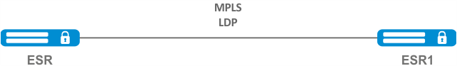
LDP is a tag distribution protocol. To find the neighbors hello messages are sent to the multicast address 224.0.0.2. When exchanging hello messages, routers learn each other's transport addresses. A router with a bigger address initializes the TCP session. After checking the parameters, the LDP session is considered established.
ESR routers support the following LDP operation modes:
- Tag information exchange mode — Downstream Unsolicited;
- Mechanism for controlling the distribution of tags — Independent Label Distribution Control;
- Label retention mode — Liberal Label Retention;
On interfaces where LDP and MPLS switching are enabled, the firewall must be disabled.
The current version LDP only works with IPv4 addresses.
Configuration algorithm
Step | Description | Command | Keys |
|---|---|---|---|
1 | In the context of MPLS parameters configuration, specify the interfaces involved in the MPLS switching process | esr(config-mpls)# forwarding interface { <IF> | <TUN> } | <IF> – an interface's name, specified in the form described in Section Types and naming order of router interfaces; <TUN> – the name of the tunnel is specified as described in section Types and naming order of router tunnels; |
2 | Specify the router-id for LDP (not necessary if transport-address is specified). | esr(config-ldp)# router-id <ID> | <ID> – router identifier, defined as AAA.BBB.CCC.DDD where each part takes values of [0..255]. |
3 | In the context of the address family ipv4 settings, specify transport-address (not necessary if router-id is specified). | esr(config-ldp-af-ipv4)# transport-address <ADDR> | <ADDR> – defined as AAA.BBB.CCC.DDD where each part takes values of [0..255]. |
3 | In the context of the address family ipv4 settings, specify interfaces for enabling LDP process. | esr(config-ldp-af-ipv4)# interface { <IF> | <TUN> } | <IF> – an interface's name, specified in the form described in Section Types and naming order of router interfaces; <TUN> – the name of the tunnel is specified as described in section Types and naming order of router tunnels. |
4 | Enable LDP process. | esr(config-ldp)# enable | |
5 | Enable explicit-null functionality (optional). | esr(config-ldp)# egress-label-type explicit-null | |
6 | In the LDP neighbor configuration mode, set the password with the password command (optional). | esr(config-ldp-neig)# password {<TEXT> | ENCRYPTED-TEXT>} | <CLEAR-TEXT> – password, sets by string of [8..16] characters; <ENCRYPTED-TEXT> – encrypted password of [8..16] bytes ([16..32] characters) in hexadecimal format (0xYYYY...) or (YYYY...). |
The following functionality is also available as part of the LDP configuration:
| |||
Configuration example
Objective:
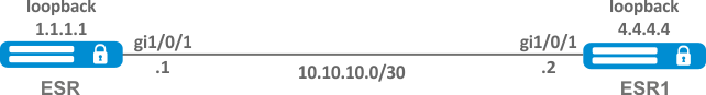
Configure LDP communication between peers.
Solution:
ESR pre-configuration:
First, IP addresses must be assigned to the interfaces, the firewall must be disabled and one of the internal routing protocols must be configured.
ESR pre-configuration:
hostname ESR
router ospf 1
  area 0.0.0.0
    enable
  exit
  enable
exit


interface gigabitethernet 1/0/1
  ip firewall disable
  ip address 10.10.10.1/30
  ip ospf instance 1
  ip ospf
exit


interface loopback 1
  ip address 1.1.1.1/32
  ip ospf instance 1
  ip ospf
exitESR1 pre-configuration:
hostname ESR1
router ospf 1
  area 0.0.0.0
    enable
  exit
  enable
exit


interface gigabitethernet 1/0/1
  ip firewall disable
  ip address 10.10.10.2/30
  ip ospf instance 1
  ip ospf
exit


interface loopback 1
  ip address 4.4.4.4/32
  ip ospf instance 1
  ip ospf
exitConfiguration on ESR:
ESR
ESR# config
ESR(config)# mpls
ESR(config-mpls)# forwarding interface gigabitethernet 1/0/1
ESR(config-mpls)# ldp
ESR(config-ldp)# router-id 1.1.1.1
ESR(config-ldp)# enable
ESR(config-ldp)# address-family ipv4
ESR(config-ldp-af-ipv4)# interface gigabitethernet 1/0/1
ESR(config-ldp-af-ipv4-if)# end
ESR#
Configuration on ESR1:
ESR1
ESR1# configure
ESR1(config)# mpls
ESR1(config-mpls)# forwarding interface gigabitethernet 1/0/1
ESR1(config-mpls)# ldp
ESR1(config-ldp)# router-id 4.4.4.4
ESR1(config-ldp)# enable
ESR1(config-ldp)# address-family ipv4
ESR1(config-ldp-af-ipv4)# interface gigabitethernet 1/0/1
ESR1(config-ldp-af-ipv4-if)# end
ESR1#Check:
Enter the following commands at one of the piers:
The output will show the parameters of the neighboring pier obtained from the multicast hello messages.
ESR# show mpls ldp discovery detailed
Local LDP ID: 1.1.1.1
Discovery sources:
    Interfaces:
        gigabitethernet 1/0/1:
                 Hello interval: 5 seconds
        Transport IP address: 1.1.1.1
        LDP ID: 4.4.4.4
            Source IP address: 10.10.10.2
            Transport IP address: 4.4.4.4
                          Hold time: 15 seconds
Proposed hold time: 90/15 (local/peer) secondsThe LDP session should be in the "Operational" state.
ESR1# show mpls ldp neighbor
Peer LDP ID: 4.4.4.4; Local LDP ID 1.1.1.1
    State: Operational
    TCP connection: 4.4.4.4:40245 - 1.1.1.1:646
    Messages sent/received: 10/11
    Uptime: 00:00:58
    LDP discovery sources:
gigabitethernet 1/0/1Configuring session parameters in LDP
By default, hello messages sent out are set to the following values:
Parameter | LDP |
|---|---|
Hello interval | 5 seconds |
Hold timer | 15 seconds |
Keepalive holdtime | 180 seconds |
Hold timer is a matching parameter — the smallest is chosen. This example shows that the ESR after matching the Hold timer is 10 seconds.
ESR# sh mpls ldp discovery detailed
Local LDP ID: 4.4.4.4
Discovery sources:
    Interfaces:
        gigabitethernet 1/0/4:
            Hello interval: 5 seconds
            Transport IP address: 4.4.4.4
            LDP ID: 1.1.1.1
                Source IP address: 10.10.10.1
                Transport IP address: 1.1.1.1
                                   Hold time: 10 seconds
Proposed hold time: 15/10 (local/peer) secondsIf after matching, the Hello interval is greater than the Hold timer, then the Hello interval will be equal to Hold timer/3.
ESR routers have the ability to flexibly configure Hello holdtime, Hello interval and Keepalive holdtime settings. Let's consider an example of configuring Hello holdtime for an LDP session:
ESR# show run mpls
mpls
  ldp
  router-id 4.4.4.4
     discovery hello holdtime 40
    address-family ipv4
      interface gigabitethernet 1/0/4
             discovery hello holdtime 60
    exit
  exit
  enable
exitIf the Hello Holdtime and Hello Interval parameters are not specified, the default values are used. If parameters are specified, the priority of values for address-family will be higher than for globally configured values.
ESR# show mpls ldp discovery detailed
Local LDP ID: 4.4.4.4
Discovery sources:
    Interfaces:
        gigabitethernet 1/0/4:
            Hello interval: 5 seconds
            Transport IP address: 4.4.4.4
            LDP ID: 1.1.1.1
                Source IP address: 10.10.10.1
                Transport IP address: 1.1.1.1
                Hold time: 15 seconds
Proposed hold time: 60 /15 (local/peer) secondsThe parameters configured in address-family can be configured for each individual interface participating in the LDP process.
ESR# show running-config mpls
mpls
  ldp
    router-id 4.4.4.4
    discovery hello holdtime 50
    discovery hello interval 10
    address-family ipv4
             interface gigabitethernet 1/0/1
                 discovery hello holdtime 60
                 discovery hello interval 20
      exit
             interface gigabitethernet 1/0/4
                 discovery hello holdtime 30
                 discovery hello interval 10
      exit
    exit
  enable
exitFor a TCP session, Keepalive holdtime is also a matching parameter similar to Hold timer. Keepalive interval is calculated automatically and equals Keepalive holdtime/3. Keepalive holdtime can be set globally as well as for each neighbor. The timer set for a particular neighbor is a higher priority.
ESR# show running-config mpls
mpls
  ldp
  router-id 4.4.4.4
     keepalive 30 // установлен в глобальной конфигурации LDP
  neighbor 1.1.1.1
     keepalive 55// установлен в соседа с адресом 1.1.1.1
  exit
exitESR# sh mpls ldp neighbor 1.1.1.1
Peer LDP ID: 1.1.1.1; Local LDP ID 4.4.4.4
State: Operational
TCP connection: 1.1.1.1:646 - 4.4.4.4:56668
Messages sent/received: 401/401
Uptime: 02:00:24
Peer holdtime: 55
Keepalive interval: 18
LDP discovery sources:Algorithm for setting Hello holdtime and Hello interval in the global LDP configuration
Step | Description | Command | Keys |
|---|---|---|---|
1 | Configure the LDP (see section LDP configuration) | ||
2 | In the LDP configuration mode, set Hello holdtime | esr(config-ldp)# discovery hello holdtime <TIME> | <TIME> — Time in seconds in the range of [3..65535] |
3 | In the LDP configuration mode, set Hello interval | esr(config-ldp)# discovery hello interval <TIME> | <TIME> — Time in seconds in the range of [3..65535] |
Algorithm for setting Hello holdtime and Hello interval for address family
Step | Description | Command | Keys |
|---|---|---|---|
1 | Configure the LDP (see section LDP configuration) | ||
2 | In the LDP address family configuration mode, set Hello holdtime on the specified interface | esr(config-ldp-af-ipv4-if)# discovery hello holdtime <TIME> | <TIME> — time in the range of [3..65535] seconds Default value: 15 |
3 | In the LDP address family configuration mode, set Hello interval on the specified interface | esr(config-ldp-af-ipv4-if)# discovery hello interval <TIME> | <TIME> — time in the range of [3..65535] seconds Default value: 5 |
Algorithm for setting Keepalive holdtime parameter in the global LDP configuration
Step | Description | Command | Keys |
|---|---|---|---|
1 | Configure the LDP (see section LDP configuration) | ||
2 | In the LDP configuration mode, set the Keepalive parameter | esr(config-ldp)# keepalive <TIME> | <TIME> — time in the range of [3..65535] seconds Default value: 180 |
Algorithm for setting Keepalive holdtime parameter for the specific neighbor
Step | Description | Command | Keys |
|---|---|---|---|
1 | Configure the LDP (see section LDP configuration) | ||
2 | In the neighbor configuration mode, set the Keepalive holdtime parameter | esr(config-ldp-neig)# keepalive <TIME> | <TIME> — time in the range of [3..65535] seconds Default value: 180 |
Configuration example
Objective:
Override hello holdtime (40 seconds) and hello interval (10 seconds) parameters for the entire LDP process. For the neighbor with address 1.1.1.1 set the Keepalive holdtime to 150 seconds.
Solution:
ESR
ESR(config)# mpls
ESR(config-mpls)# ldp
ESR(config-ldp)# discovery hello holdtime 40
ESR(config-ldp)# discovery hello interval 10
ESR(config-ldp)# neighbor 1.1.1.1
ESR(config-ldp-neig)# keepalive 150Check:
To view hello parameters:
ESR
ESR# sh mpls ldp discovery detailed
Local LDP ID: 4.4.4.4
Discovery sources:
    Interfaces:
        gigabitethernet 1/0/4:
            Hello interval:       10 seconds
            Transport IP address: 4.4.4.4
            LDP ID:               1.1.1.1
                Source IP address:    10.10.10.1
                Transport IP address: 1.1.1.1
                Hold time:            15 seconds
                Proposed hold time:   40/15 (local/peer) seconds
To view parameter of the established TCP session:
ESR
ESR# sh mpls ldp neighbor 1.1.1.1
Peer LDP ID: 1.1.1.1; Local LDP ID 4.4.4.4
    State:                  Operational
    TCP connection:         1.1.1.1:646 - 4.4.4.4:45414
    Messages sent/received: 15/15
    Uptime:                 00:06:31
    Peer holdtime:          150
    Keepalive interval:     50
    LDP discovery sources:
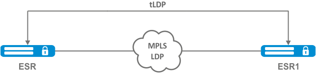
Configuring session parameters in targeted-LDP
By default, the targeted LDP session is set to the following values:
Parameter | targeted-LDP |
|---|---|
hello interval | 5 seconds |
Hold timer | 45 seconds |
Keepalive holdtime | 180 seconds |
Hold timer is a matching parameter — the smallest is chosen. This example shows that the ESR after matching set 30 seconds:
ESR1# sh mpls ldp discovery detailed

...
Targeted hellos:
1.1.1.1 -> 4.4.4.4:
Hello interval: 2 seconds
Transport IP address: 1.1.1.1
LDP ID: 4.4.4.4
Source IP address: 4.4.4.4
Transport IP address: 4.4.4.4
Hold time: 30 seconds
Proposed hold time: 30/45 (local/peer) secondsIf after matching, the Hello interval is greater than the Hold timer, then the Hello interval will be equal to Hold timer/3.
ESR routers have the possibility to flexibly configure Hello holdtime, Hello interval and Keepalive holdtime parameters: the parameters can be set for the entire LDP process, as well as for the corresponding neighbor.
Example output for the LDP process:
ESR# sh running-config mpls
mpls
  ldp
    router-id 1.1.1.1
         keepalive 160
         discovery targeted-hello holdtime 30
         discovery targeted-hello interval 10
  exit
exitExample output for a targeted-LDP session for a particular neighbor:
ESR# sh running-config mpls
mpls
  ldp
    router-id 1.1.1.1
    neighbor 4.4.4.4
      keepalive 160
      targeted
      discovery targeted-hello holdtime 30
      discovery targeted-hello interval 45
    exit
  exit
exitIf parameters are set for both the LDP process and a specific neighbor, the priority will be the settings set for the neighbor.
ESR# sh running-config mpls
mpls
  ldp
    router-id 1.1.1.1
    keepalive  160
    discovery hello holdtime 90
    discovery targeted-hello interval 30
    neighbor 4.4.4.4
      keepalive 140
      targeted
      discovery targeted-hello holdtime 45
      discovery targeted-hello interval 15
    exit
  exit
exitESR# show mpls ldp discovery detailed
...
Targeted hellos:
1.1.1.1 -> 4.4.4.4:
Hello interval: 15 seconds
Transport IP address: 1.1.1.1
LDP ID: 4.4.4.4
Source IP address: 4.4.4.4
Transport IP address: 4.4.4.4
Hold time: 45 seconds
Proposed hold time: 45/45 (local/peer) seconds
ESR# show mpls ldp neighbor 4.4.4.4
Peer LDP ID: 4.4.4.4; Local LDP ID 1.1.1.1
State: Operational
TCP connection: 4.4.4.4:51861 - 1.1.1.1:646
Messages sent/received: 10/10
Uptime: 00:00:09
Peer holdtime: 140
Keepalive interval: 46
LDP discovery sources:
1.1.1.1 -> 4.4.4.4:Algorithm for setting Hello holdtime, Hello interval and Keepalive holdtime for the LDP process
1 | Configure the LDP (see section LDP configuration) | ||
2 | In the LDP configuration mode, set Hello holdtime | esr(config-ldp)# discovery targeted-hello holdtime <TIME> | <TIME> — time in the range of [3..65535] seconds Default value: 45 |
3 | In the LDP configuration mode, set Hello interval | esr(config-ldp)# discovery targeted- hello interval <TIME> | <TIME> — time in the range of [1..65535] seconds Default value: 5 |
4 | In the LDP configuration mode, set Keepalive holdtime | esr(config-ldp)# keepalive <TIME> | <TIME> — time in the range of [3..65535] seconds Default value: 180 |
Algorithm for setting Hello holdtime, Hello interval and Keepalive holdtime for the specific neighbor
1 | Configure the LDP (see section LDP configuration) | ||
2 | In the LDP neighbor configuration mode, set Hello holdtime | esr(config-ldp-neig)# discovery targeted-hello holdtime <TIME> | <TIME> — time in the range of [3..65535] seconds Default value: 45 |
3 | In the LDP neighbor configuration mode, set Hello interval | esr(config-ldp-neig)# discovery targeted- hello interval <TIME> | <TIME> — time in the range of [1..65535] seconds Default value: 5 |
4 | In the LDP neighbor configuration mode, set Keepalive holdtime | esr(config-ldp-neig)# keepalive <TIME> | <TIME> — time in the range of [3..65535] seconds Default value: 180 |
Configuration example
Objective:
Override hello holdtime (120 seconds) and hello interval (30 seconds) parameters for the entire targeted-LDP process. For the neighbor with address 4.4.4.4 set the Keepalive holdtime to 150 seconds.
Solution:
ESR
ESR(config)# mpls
ESR(config-mpls)# ldp
ESR(config-ldp)# discovery targeted-hello holdtime 40
ESR(config-ldp)# discovery targeted-hello interval 10
ESR(config-ldp)# neighbor 4.4.4.4
ESR(config-ldp-neig)# keepalive 150Check:
To view hello parameters of the targeted LDP session:
ESR
ESR1# sh mpls ldp discovery detailed
...
    Targeted hellos:
         1.1.1.1 -> 4.4.4.4:
            Hello interval:       10 seconds
            Transport IP address: 1.1.1.1
            LDP ID:               4.4.4.4
                Source IP address:    4.4.4.4
                Transport IP address: 4.4.4.4
                Hold time:            40 seconds
                Proposed hold time:   40/45 (local/peer) seconds
To view parameter of the established TCP session:
ESR
ESR# sh mpls ldp neighbor 4.4.4.4
Peer LDP ID: 4.4.4.4; Local LDP ID 1.1.1.1
    State:                  Operational
    TCP connection:         4.4.4.4:34879 - 1.1.1.1:646
    Messages sent/received: 11/11
    Uptime:                 00:01:05
    Peer holdtime:          150
    Keepalive interval:     50
    LDP discovery sources:
         1.1.1.1 -> 4.4.4.4:
            Hello interval: 10 seconds
            Holdtime:       40 seconds
...LDP tag filtering configuration
By default, routers allocate a separate label to each FEC. There are scenarios when it is necessary to allocate MPLS tags only for certain FECs.
Configuration algorithm
Step | Description | Command | Keys |
|---|---|---|---|
1 | Configure the LDP (see section LDP configuration) | ||
2 | Create network type object-group | esr(config)# object-group network <NAME> | <NAME> – name of a subnet list being configured, set by the string of up to 31 characters. |
3 | Describe the subnets for which labels will be assigned | esr(config-object-group-network)# ip prefix <ADDR/LEN> | <ADDR/LEN> – IP address and subnet mask, defined as AAA.BBB.CCC.DDD/EE where each part AAA-DDD takes values of [0..255] and EE takes values of [1..32]; |
4 | In the context of the LDP configuration, apply the created object-group | esr(config-ldp)# advertise-labels <NAME> | <NAME> – name of a subnet list being configured, set by the string of up to 31 characters. |
Tags will be allocated ONLY to the subnets described in the object-group, regardless of how they were learned (connected, local, IGP, etc.).
Prefixes must be described in the object-group.
The prefix must have an exact match with the route from the FIB.
This functionality is supported for IPv4.
Configuration example
Objective:
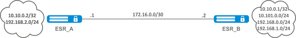
Assign MPLS tags only to FEC 10.10.0.2/32 and 10.10.0.1/32.
Solution:
On ESR_A and ESR_B create an object-group ADV_LABELS type network and add to it the prefixes 10.10.0.1/32 and 10.10.0.2/32 respectively.
ESR_A
esr(config)# object-group network ADV_LABELS
esr(config-object-group-network)# ip prefix 10.10.0.1/32
esr(config-object-group-network)# ip prefix 10.10.0.2/32ESR_B
esr(config)# object-group network ADV_LABELS
esr(config-object-group-network)# ip prefix 10.10.0.1/32
esr(config-object-group-network)# ip prefix 10.10.0.2/32
Apply the created object-group on both routers:
ESR_A и ESR_B
esr(config)# mpls
esr(config-ldp)# ldp
esr(config-ldp)# advertise-labels ADV_LABELSCheck:
On ESR_B make sure that the tag is assigned to the appropriate prefixes:
esr# sh mpls ldp bindings 10.10.0.1/32
10.10.0.1/32
local label: exp-null
remote label: 75 lsr: 172.16.0.1And not assigned to 192.168.2.0/24
esr# sh mpls ldp bindings 192.168.2.0/24
esr#L2VPN Martini mode configuration
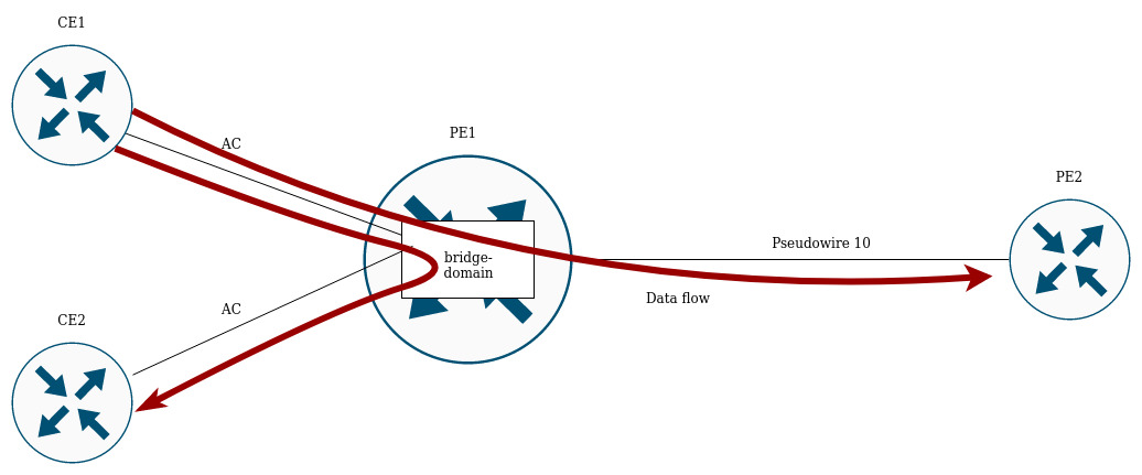
L2VPN allows you to organize ethernet frames transmission through the MPLS domain. Allocation and distribution of tunnel labels, in this mode, is carried out by means of the LDP. In the implementation of L2VPN can be divided into two cases:
- P2P — "point-to-point" tunnel
- VPLS — "point-to-multipoint" tunnel
In both cases, a virtual channel (pseudo-wire) is created to transmit ethernet frames between routers. To negotiate pseudo-wire parameters, as well as to allocate and transfer tunnel labels between routers, an LDP session is established in the targeted mode.
L2VPN VPWS configuration algorithm
Step | Description | Command | Keys |
|---|---|---|---|
1 | Configure the LDP (see section LDP configuration). | ||
2 | Create pw-class in the system and switch to the pw-class configuration mode. | esr(config-l2vpn)# pw-class <WORD> | <WORD> — pw-class name [1..31] characters long. |
3 | Add a description for pw-class (optional). | esr(config-l2vpn-pw-class)# description <LINE> | <LINE> – description. Set by the string [1..255] characters long. |
4 | Set the MTU value for the pseudo-wire included in the pw-class (optional). | esr(config-l2vpn-pw-class)# encapsulation | <MTU> — MTU value, takes values in the range of [552..10000] Default value: 1500. |
5 | Disable status-tlv messaging (optional). | esr(config-l2vpn-pw-class)# encapsulation | Default value: status-tlv enable |
6 | Create p2p-class in the system and switch to the p2p-class configuration mode. | esr(config-l2vpn)# p2p <NAME> | <NAME> — name of the p2p service, set by the string of up to 31 characters. |
7 | Specify Attached Circuit interface. | esr(config-l2vpn-p2p)# interface | <IF> – an interface's name, specified in the form described in Section Types and naming order of router interfaces; <TUN> – the name of the tunnel is specified as described in section Types and naming order of router tunnels. |
8 | Enable p2p tunnel. | esr(config-l2vpn-p2p)# enable | |
9 | Specify transport mode (optional). | esr(config-l2vpn-p2p)# transport-mode | <ethernet> — mode in which the 802.1Q tag is removed from the header when entering pseudo-wire; <vlan> — mode in which the 802.1Q tag can be saved when transmitted over pseudo-wire. Default value: ethernet |
10 | Create a pseudo-wire and switch to its parameters configuration mode | esr(config-l2vpn-p2p)# pw <PW_ID> <LSR_ID> | <PW_ID> — psewdowire identifier, specified in the range [1..4294967295] <LSR_ID> — identifier of LSR to which pseudo-wire is built, specified as AAA.BBB.CCC.DDD, where each part takes values [0..255] |
11 | Add a description for pseudo-wire (optional). | esr(config-l2vpn-pw)# description <LINE> | <LINE> – description. Set by the string [1..255] characters long. |
12 | Set pw-class for pseudo-wire. | esr(config-l2vpn-pw)# pw-class <WORD> | <WORD> — pw-class name [1..31] characters long. |
13 | Set the LSR address to which the pseudo-wire is set (Optional if the neighbor address is the same as the LSR_ID). | esr(config-l2vpn-pw)# neighbor-address <ADDR> | <ADDR> – router IP address, defined as AAA.BBB.CCC.DDD where each part takes values of [0..255]. |
14 | Enable pseudo-wire. | esr(config-l2vpn-pw)# enable | |
If it is necessary to change the default settings for a targeted LDP session, see section Configuring session parameters in targeted-LDP. | |||
L2VPN VPWS configuration example
Objective:
Configure l2vpn so that ge1/0/2.100 interface of the CE1 router and ge1/0/2.100 interface of the CE2 router operate within the same broadcast domain.
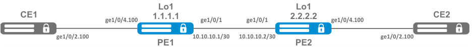
Solution:
Pre-requisite:
- Enable Jumbo frames support with the "system jumbo-frames" command (the device must be rebooted for the changes to take effect);
- Сonfigure IP addresses on interfaces according to the network structure shown in the figure above;
- Organize the exchange of routes between PE1 and PE2 using IGP (OSPF, IS-IS, RIP).
On the PE1 router create a sub-interface from which traffic from CE1 will be received:
PE1# configure
PE1(config)# interface gigabitethernet 1/0/4.100
PE1(config-subif)# exitSet the MTU value on the interface towards PE2 to 9600 to avoid MTU overrun after encapsulating the MPLS header and disable the firewall:
PE1#(config)# interface gigabitethernet 1/0/1
PE1(config-if-gi)# mtu 9600
PE1(config-if-gi)# ip firewall disable
PE1(config-if-gi)# exitAllow packets with an MPLS header to be received on the interface towards the MPLS network (in this example, the interface towards PE2):
PE1(config)# mpls
PE1(config-mpls)# forwarding interface gigabitethernet 1/0/1Configure the LDP protocol and enable neighbor detection on the interface towards PE2:
PE1(config-mpls)# ldp
PE1(config-ldp)# router-id 1.1.1.1
PE1(config-ldp)# address-family ipv4
PE1(config-ldp-af-ipv4)# interface gigabitethernet 1/0/1
PE1(config-ldp-af-ipv4-if)# exit
PE1(config-ldp-af-ipv4)# transport-address 1.1.1.1
PE1(config-ldp-af-ipv4)# exit
PE1(config-ldp)# enable
PE1(config-ldp)# exitCreate a pw-class on the basis of which the virtual channel (pw) will be created later. Since, in this example, the default parameters will be applied to pw, it will be sufficient to specify the class name:
PE1(config-mpls)# l2vpn
PE1(config-l2vpn)# pw-class for_p2p_VLAN100
PE1(config-l2vpn-pw-class)# exitCreate a new l2vpn of type p2p and add pw to router PE3, take the pw identifier as VID for convenience (in this case = 100):
PE1(config-l2vpn)# p2p to_PE2_VLAN100
PE1(config-l2vpn-p2p)# interface gigabitethernet 1/0/4.100
PE1(config-l2vpn-p2p)# pw 100 3.3.3.3
PE1(config-l2vpn-pw)# pw-class for_p2p_VLAN100
PE1(config-l2vpn-pw)# enable
PE1(config-l2vpn-pw)# exit
PE1(config-l2vpn-p2p)# enable
PE1(config-l2vpn-p2p)# endApply the configuration:
PE1# commit
PE1# confirmConfigure the PE2 router in the same way as PE1:
PE2# configure
PE2(config)# interface gigabitethernet 1/0/4.100
PE2(config-subif)# exit
PE2#(config)# interface gigabitethernet 1/0/1
PE2(config-if-gi)# mtu 9600
PE1(config-if-gi)# ip firewall disable
PE1(config-if-gi)# exit
PE2(config)# mpls
PE2(config-mpls)# forwarding interface gigabitethernet 1/0/1
PE2(config-mpls)# ldp
PE2(config-ldp)# router-id 2.2.2.2
PE2(config-ldp)# address-family ipv4
PE2(config-ldp-af-ipv4)# interface gigabitethernet 1/0/1
PE2(config-ldp-af-ipv4-if)# exit
PE2(config-ldp-af-ipv4)# transport-address 2.2.2.2
PE2(config-ldp-af-ipv4)# exit
PE2(config-ldp)# enable
PE2(config-ldp)# exit
PE2(config-mpls)# l2vpn
PE2(config-l2vpn)# pw-class for_p2p_VLAN100
PE2(config-l2vpn-pw-class)# exit
PE2(config-l2vpn)# p2p to_PE1_VLAN100
PE2(config-l2vpn-p2p)# interface gigabitethernet 1/0/4.100
PE2(config-l2vpn-p2p)# pw 100 1.1.1.1
PE2(config-l2vpn-pw)# pw-class for_p2p_VLAN100
PE2(config-l2vpn-pw)# enable
PE2(config-l2vpn-pw)# exit
PE2(config-l2vpn-p2p)# enable
PE2(config-l2vpn-p2p)# end
PE2# commit
PE2# confirmMake sure that the LDP neighborhood is established and display the virtual channel status (pseudowire) between PE1 and PE2
PE2# show mpls ldp neighbor
Peer LDP ID: 1.1.1.1; Local LDP ID 2.2.2.2
    State: Operational
    TCP connection: 1.1.1.1:646 - 2.2.2.2:34625
    Messages sent/received: 12/12
    Uptime: 00:03:50
    LDP discovery sources:
2.2.2.2 -> 1.1.1.1PE2# show mpls l2vpn pseudowire
Neighbor PW ID Type Status
--------------------------------------- ---------- ---------- ------
1.1.1.1 100 Ethernet UpThe LDP neighborhood is established, pseudowire has moved to 'UP' status. The l2vpn p2p type configuration is now complete.
L2VPN VPLS configuration algorithm
Step | Description | Command | Keys |
|---|---|---|---|
1 | Configure the LDP (see section LDP configuration). | ||
2 | Create a network bridge in the system without specifying an IP address (see section Bridge configuration). | ||
3 | Create pw-class in the system and switch to the pw-class configuration mode. | esr(config-l2vpn)# pw-class <WORD> | <WORD> — pw-class name [1..31] characters long. |
4 | Add a description for pw-class (optional). | esr(config-l2vpn-pw-class)# description <LINE> | <LINE> — description. Set by the string [1..255] characters long. |
5 | Set the MTU value for the pseudo-wire included in the pw-class (optional). | esr(config-l2vpn-pw-class)# encapsulation | <MTU> — MTU value, takes values in the range of [552..10000] Default value: 1500. |
6 | Disable status-tlv messaging (optional). | esr(config-l2vpn-pw-class)# encapsulation | Default value: status-tlv enable |
7 | Create VPLS domain in the system and switch to the VPLS domain configuration mode. | esr(config-l2vpn)# vpls <NAME> | <NAME> — name of the p2p service, set by the string of up to 31 characters. |
8 | Enable VPLS tunnel. | esr(config-l2vpn-vpls)# enable | |
9 | Add bridge domain. | esr (config-l2vpn-vpls)# bridge-group <ID> | <ID> — bridge domain identifier, specified in the range [1..250] |
10 | Specify transport mode (optional). | esr(config-l2vpn-vpls)# transport-mode | <ethernet> — mode in which the 802.1Q tag is removed from the header when entering pseudo-wire; |
11 | Create a pseudo-wire and switch to its parameters configuration mode | esr(config-l2vpn-vpls)# pw <PW_ID> <LSR_ID> | <PW_ID> — psewdowire identifier, specified in the range [1..4294967295] <LSR_ID> — identifier of LSR to which pseudo-wire is built, specified as AAA.BBB.CCC.DDD, where each part takes values [0..255] |
12 | Add a description for pseudo-wire (optional). | esr(config-l2vpn-pw)# description <LINE> | <LINE> — description. Set by the string [1..255] characters long. |
13 | Set pw-class for pseudo-wire | esr(config-l2vpn-pw)# pw-class <WORD> | <WORD> — pw-class name [1..31] characters long. |
14 | Set the LSR address to which the pseudo-wire is set (Optional if the neighbor address is the same as the LSR_ID). | esr(config-l2vpn-pw)# neighbor-address <ADDR> | <ADDR> – router IP address, defined as AAA.BBB.CCC.DDD where each part takes values of [0..255]. |
15 | Enable pseudo-wire. | esr(config-l2vpn-pw)# enable | |
16 | If the topology of the VPLS domain to be created requires more than one pseudo-wire, repeat steps 10 to 14. | ||
17 | If it is necessary to change the default settings for a targeted LDP session, see section Configuring session parameters in targeted-LDP. | ||
L2VPN VPLS configuration example
Objective:
Configure l2vpn so that CE1, CE2, CE3 routers have L2 connectivity through the gi1/0/2.100 and gi1/0/4 (CE2) interfaces.
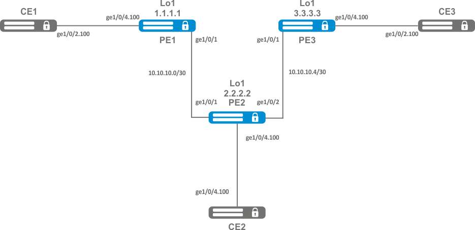
Solution:
Pre-requisite:
- Enable Jumbo frames support with the "system jumbo-frames" command (the device must be rebooted for the changes to take effect);
- Сonfigure IP addresses on interfaces according to the network structure shown in the figure above;
- Organize the exchange of routes between PE1, PE2 and PE3 using IGP (OSPF, IS-IS);
On router PE1, create a bridge group and enable it:
PE1# configure
PE1(config)# bridge 10
PE1(config-bridge)# enable
PE1(config-bridge)# exitOn the Interface to the CE1 side, include it in the created bridge group:
PE1(config)# interface gigabitethernet 1/0/4.100
PE1(config-subif)# bridge-group 10
PE1(config-subif)# exitSet the MTU value on the interface towards PE2 to 9600 to avoid MTU overrun after encapsulating the MPLS header and disable the firewall
PE1#(config)# interface gigabitethernet 1/0/1
PE1(config-if-gi)# mtu 9600
PE1(config-if-gi)# ip firewall disable
PE1(config-if-gi)# exitAllow packets with an MPLS header to be received on the interface towards the MPLS network (in this example, the interface towards PE2):
PE1(config)# mpls
PE1(config-mpls)# forwarding interface gigabitethernet 1/0/1Configure the LDP protocol and enable neighbor detection on the interface towards PE2:
PE1(config-mpls)# ldp
PE1(config-ldp)# router-id 1.1.1.1
PE1(config-ldp)# address-family ipv4
PE1(config-ldp-af-ipv4)# interface gigabitethernet 1/0/1
PE1(config-ldp-af-ipv4-if)# exit
PE1(config-ldp-af-ipv4)# transport-address 1.1.1.1
PE1(config-ldp-af-ipv4)# exit
PE1(config-ldp)# enable
PE1(config-ldp)# exitCreate a pw-class on the basis of which the virtual channels (pw) will be created later. Since, in this example, the default parameters will be applied to pw, it will be sufficient to specify the class name:
PE1(config-mpls)# l2vpn
PE1(config-l2vpn)# pw-class for_vpls1
PE1(config-l2vpn-pw-class)# exitCreate a new l2vpn of vpls type and add pw to routers PE2 and PE3, take the pw identifier as VID for convenience (in this case = 100):
PE1(config-l2vpn)# vpls vpls1
PE1(config-l2vpn-vpls)# bridge-group 10
PE1(config-l2vpn-vpls)# pw 100 2.2.2.2
PE1(config-l2vpn-pw)# pw-class for_vpls1
PE1(config-l2vpn-pw)# enable
PE1(config-l2vpn-pw)# exit
PE1(config-l2vpn-vpls)# pw 100 3.3.3.3
PE1(config-l2vpn-pw)# pw-class for_vpls1
PE1(config-l2vpn-pw)# enable
PE1(config-l2vpn-pw)# exit
PE1(config-l2vpn-vpls)# enable
PE1(config-l2vpn-vpls)# endApply the created configuration:
PE1# commit
PE1# confirm Configure PE2 and PE3 routers in the same way as PE1:
PE2# configure
PE2(config)# bridge 10
PE2(config-bridge)# enable
PE2(config-bridge)# exit
PE2(config)# interface gigabitethernet 1/0/4.100
PE2(config-subif)# bridge-group 10
PE2(config-subif)# exit
PE2(config)# interface gigabitethernet 1/0/2
PE2(config-if-gi)# mtu 9600
PE2(config-if-gi)# ip firewall disable
PE2(config-if-gi)# exit
PE2(config)# mpls
PE2(config-mpls)# forwarding interface gigabitethernet 1/0/1
PE2(config-mpls)# forwarding interface gigabitethernet 1/0/2
PE2(config-mpls)# ldp
PE2(config-ldp)# enable
PE2(config-ldp)# router-id 2.2.2.2
PE2(config-ldp)# address-family ipv4
PE2(config-ldp-af-ipv4)# transport-address 2.2.2.2
PE2(config-ldp-af-ipv4)# interface gigabitethernet 1/0/1
PE2(config-ldp-af-ipv4-if)# exit
PE2(config-ldp-af-ipv4)# interface gigabitethernet 1/0/2
PE2(config-ldp-af-ipv4-if)# exit
PE2(config-ldp-af-ipv4)# exit
PE2(config-ldp)# exit
PE2(config-mpls)# l2vpn
PE2(config-l2vpn)# pw-class for_vpls1
PE2(config-l2vpn-pw-class)# exit
PE2(config-l2vpn)# vpls vpls1
PE2(config-l2vpn-vpls)# enable
PE2(config-l2vpn-vpls)# bridge-group 10
PE2(config-l2vpn-vpls)# pw 100 1.1.1.1
PE2(config-l2vpn-pw)# pw-class for_vpls1
PE2(config-l2vpn-pw)# enable
PE2(config-l2vpn-pw)# exit
PE2(config-l2vpn-vpls)# pw 100 3.3.3.3
PE2(config-l2vpn-pw)# pw-class for_vpls1
PE2(config-l2vpn-pw)# enable
PE2(config-l2vpn-pw)# end
PE2# commit
PE2# confirm
PE3(config)# bridge 10
PE3(config-bridge)# enable
PE3(config-bridge)# exit
PE3(config)# interface gigabitethernet 1/0/4.100
PE3(config-subif)# bridge-group 10
PE3(config-subif)# exit
PE3(config)# interface gigabitethernet 1/0/1
PE3(config-if-gi)# mtu 9600
PE3(config-if-gi)# ip firewall disable
PE3(config-if-gi)# exit
PE3(config)# mpls
PE3(config-mpls)# forwarding interface gigabitethernet 1/0/1
PE3(config-mpls)# exit
PE3(config)# mpls
PE3(config-mpls)# ldpPE3(config-ldp)# enable
PE3(config-ldp)# router-id 3.3.3.3
PE3(config-ldp)# address-family ipv4
PE3(config-ldp-af-ipv4)# interface gigabitethernet 1/0/1
PE3(config-ldp-af-ipv4-if)# exit
PE3(config-ldp-af-ipv4)# transport-address 3.3.3.3
PE3(config-ldp-af-ipv4)# exit
PE3(config-ldp)# exit
PE3(config-mpls)# l2vpn
PE3(config-l2vpn)# pw-class for_vpls
PE3(config-l2vpn-pw-class)# exit
PE3(config-l2vpn)# vpls vpls1
PE3(config-l2vpn-vpls)# enable
PE3(config-l2vpn-vpls)# bridge-group 10
PE3(config-l2vpn-vpls)# pw 100 2.2.2.2
PE3(config-l2vpn-pw)# pw-class for_vpls
PE3(config-l2vpn-pw)# enable
PE3(config-l2vpn-pw)# exit
PE3(config-l2vpn-vpls)# pw 100 1.1.1.1
PE3(config-l2vpn-pw)# pw-class for_vpls
PE3(config-l2vpn-pw)# enable
PE3(config-l2vpn-pw)# end
PE3# commit
PE3# confirmMake sure that the LDP neighborhood is established and display the virtual channel status (pseudowire) between PE1, PE2 and PE3:
PE3# show mpls ldp neighbor
Peer LDP ID: 1.1.1.1; Local LDP ID 3.3.3.3
    State: Operational
    TCP connection: 1.1.1.1:646 - 3.3.3.3:45979
    Messages sent/received: 22/22
    Uptime: 00:13:16
    LDP discovery sources:
        3.3.3.3 -> 1.1.1.1
Peer LDP ID: 2.2.2.2; Local LDP ID 3.3.3.3
    State: Operational
    TCP connection: 2.2.2.2:646 - 3.3.3.3:59627
    Messages sent/received: 22/22
    Uptime: 00:13:20
    LDP discovery sources:
        3.3.3.3 -> 2.2.2.2
        gigabitethernet 1/0/1
PE3# show mpls l2vpn pseudowire
Neighbor                                   PW ID    Type          Status
--------------------------------------- ----------      ----------       ------
1.1.1.1                                      100        Ethernet     Up
2.2.2.2 100 Ethernet UpThe LDP neighborhood is established, pseudowire has moved to 'UP' status. The l2vpn configuration is now complete.
L2VPN Kompella mode configuration
Unlike Martini mode, where all operation is done by the LDP, in this mode the LDP does only operate with transport labels. Autodetection (not typical of LDP signaling), and the construction of a pseudowire connection is entrusted to BGP.
L2VPN VPLS configuration algorithm
Step | Description | Command | Keys |
|---|---|---|---|
1 | Configure the LDP (see section LDP configuration). | ||
2 | Create a network bridge in the system without specifying an IP address (see section Bridge configuration). | ||
3 | Create VPLS domain in the system and switch to the VPLS domain configuration mode. | esr(config-l2vpn)# vpls <NAME> | <NAME> — name of the p2p service, set by the string of up to 31 characters. |
4 | Enable VPLS tunnel. | esr(config-l2vpn-vpls)# enable | |
5 | Add bridge domain. | esr(config-l2vpn-vpls)# bridge-group <ID> | <ID> — bridge domain identifier, specified in the range [1..250]. |
6 | Switch to the autodiscovery bgp configuration context. | esr(config-l2vpn-vpls)# autodiscovery bgp | |
7 | Specify route distinguisher for the given VPLS instance. | esr(config-bgp)# rd <RD> | <RD> – Route distinguisher value, specified in one of the following forms:
|
8 | Specify route target import for the given VPLS instance. | esr(config-bgp)# route-target import <RT> | <RT> – Route-target value, specified in one of the following forms:
|
9 | Specify route target export for the given VPLS instance. | esr(config-bgp)# route-target export <RT> | <RT> – Route-target value, specified in one of the following forms:
|
10 | Specify ve id. | esr(config-bgp)# ve id <ID> | <ID> — VPLS instance identifier, specified in the range [1..16384]. |
11 | Specify vpn id. | esr (config-bgp)# vpn id <ID> | <ID> — VPN identifier, specified in the range [1..4294967295] |
12 | Specify ve range (optional). | esr (config-bgp)# ve range <RANGE> | <RANGE> — range of VPLS border device identifiers [8..100]. |
13 | Specify mtu (optional). | esr (config-bgp)# mtu <VALUE> | <VALUE> — MTU value [552..10000]. |
14 | Enable ignoring encapsulation type (optional). | esr(config-bgp)# ignore encapsulation-mismatch | |
15 | Enable ignoring MTU values (optional). | esr(config-bgp)# ignore mtu-mismatch | |
16 | In the context of address-family l2vpn vpls BGP configuration, enable extended attribute transfer. | esr(config-bgp-neighbor-af)# send-community extended |
L2VPN VPLS configuration example
Objective:
Configure L2VPN service: all CE devices must work within the same broadcast domain.
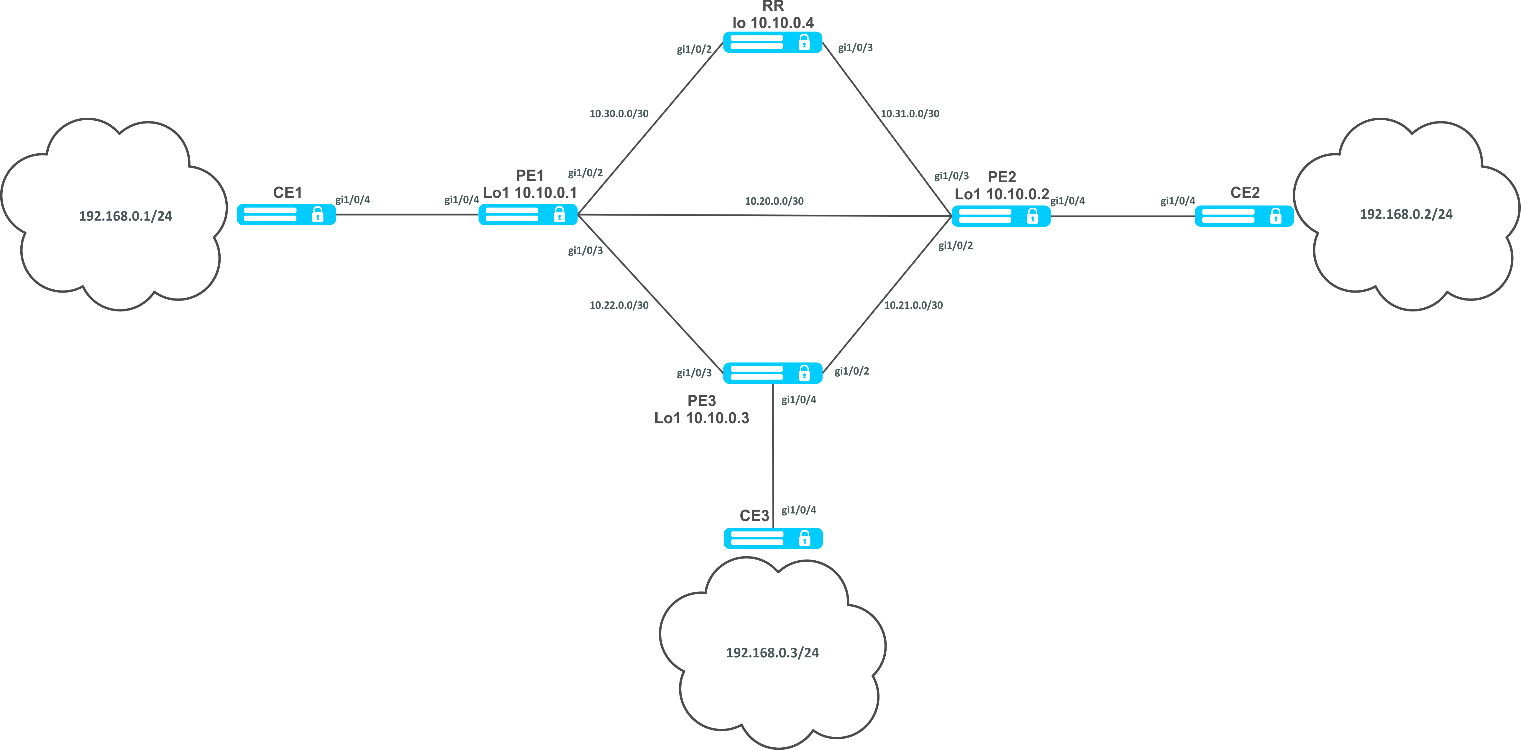
Solution:
Pre-requisite:
- Enable Jumbo frames support with the "system jumbo-frames" command (the device must be rebooted for the changes to take effect);
- Сonfigure IP addresses on interfaces according to the network structure shown in the figure above;
- Organize the exchange of routes between PE1, PE2, PE3 and RR using IGP (OSPF, IS-IS).
First, configure the RR router:
hostname RR

system jumbo-frames

router ospf 1
area 0.0.0.0
enable
exit
enable
exit

interface gigabitethernet 1/0/2
mtu 9500
ip firewall disable
ip address 10.30.0.2/30
ip ospf instance 1
ip ospf
exit
interface gigabitethernet 1/0/3
mtu 9500
ip firewall disable
ip address 10.31.0.2/30
ip ospf instance 1
ip ospf
exit
interface loopback 1
ip address 10.10.0.4/32
ip ospf instance 1
ip ospf
exit
mpls
ldp
router-id 10.10.0.4
address-family ipv4
interface gigabitethernet 1/0/2
exit
interface gigabitethernet 1/0/3
exit
exit
enable
exit
forwarding interface gigabitethernet 1/0/2
forwarding interface gigabitethernet 1/0/3
exitConfigure the BGP Route Reflector for the address family l2vpn:
RR(config)# router bgp 65500
RR(config-bgp)#   router-id 10.10.0.4
RR(config-bgp)#   neighbor 10.10.0.1
RR(config-bgp-neighbor)#     remote-as 65500
RR(config-bgp-neighbor)#     route-reflector-client
RR(config-bgp-neighbor)#     update-source 10.10.0.4
RR(config-bgp-neighbor)#     address-family l2vpn vpls
RR(config-bgp-neighbor-af)#       send-community extended
RR(config-bgp-neighbor-af)#       enable
RR(config-bgp-neighbor-af)#     exit
RR(config-bgp-neighbor)#     enable
RR(config-bgp-neighbor)#   exit
RR(config-bgp)#   neighbor 10.10.0.2
RR(config-bgp-neighbor)#     remote-as 65500
RR(config-bgp-neighbor)#     route-reflector-client
RR(config-bgp-neighbor)#     update-source 10.10.0.4
RR(config-bgp-neighbor)#     address-family l2vpn vpls
RR(config-bgp-neighbor-af)#       send-community extended
RR(config-bgp-neighbor-af)#       enable
RR(config-bgp-neighbor-af)#     exit
RR(config-bgp-neighbor)#     enable
RR(config-bgp-neighbor)#   exit
RR(config-bgp)#   neighbor 10.10.0.3
RR(config-bgp-neighbor)#     remote-as 65500
RR(config-bgp-neighbor)#     route-reflector-client
RR(config-bgp-neighbor)#     update-source 10.10.0.4
RR(config-bgp-neighbor)#     address-family l2vpn vpls
RR(config-bgp-neighbor-af)#       send-community extended
RR(config-bgp-neighbor-af)#       enable
RR(config-bgp-neighbor-af)#     exit
RR(config-bgp-neighbor)#     enable
RR(config-bgp-neighbor)#   exit
RR(config-bgp)#   enable
Next, configure BGP on the PE routers:
Pre-configuration
hostname PE1

system jumbo-frames

router ospf 1
area 0.0.0.0
enable
exit
enable
exit

interface gigabitethernet 1/0/1
mtu 9500Pre-configuration
ip firewall disable
ip address 10.20.0.1/30
ip ospf instance 1
ip ospfexit
interface gigabitethernet 1/0/2
mtu 9500
ip firewall disable
ip address 10.30.0.1/30
ip ospf instance 1
ip ospf
exitinterface gigabitethernet 1/0/3
mtu 9500
ip firewall disable
ip address 10.22.0.1/30
ip ospf instance 1
ip ospf
exit
interface loopback 1
ip address 10.10.0.1/32
ip ospf instance 1
ip ospf
exit
mpls
ldp
router-id 10.10.0.1
address-family ipv4
interface gigabitethernet 1/0/1
exit
interface gigabitethernet 1/0/2
exit
interface gigabitethernet 1/0/3
exit

exit

enable

exit
forwarding interface gigabitethernet 1/0/1
forwarding interface gigabitethernet 1/0/2
forwarding interface gigabitethernet 1/0/3
exitBGP configuration:
PE1(config)# router bgp 65500
PE1(config-bgp)#   neighbor 10.10.0.4
PE2(config-bgp)#   router-id 10.10.0.1
PE1(config-bgp-neighbor)#     remote-as 65500
PE1(config-bgp-neighbor)#     update-source 10.10.0.1
PE1(config-bgp-neighbor)#     address-family l2vpn vpls
PE1(config-bgp-neighbor-af)#       send-community extended
PE1(config-bgp-neighbor-af)#       enable
PE1(config-bgp-neighbor-af)#     exit
PE1(config-bgp-neighbor)#     enable
PE1(config-bgp-neighbor)#   exit
PE1(config-bgp)#   enable
PE1(config-bgp)# exit
Check that the BGP session with RR is successfully established:
PE1# sh ip bgp neighbors
BGP neighbor is 10.10.0.4
BGP state: Established
Neighbor address: 10.10.0.4
Neighbor AS: 65500
Neighbor ID: 10.10.0.4
Neighbor caps: refresh enhanced-refresh restart-aware AS4
Session: internal multihop AS4
Source address: 10.10.0.1
Weight: 0
Hold timer: 110/180
Keepalive timer: 21/60
Uptime: 7375 sConfiguration of BGP on PE2:
Предварительная конфигурация
hostname PE2

system jumbo-frames

router ospf 1
area 0.0.0.0
enable
exit
enable
exitPre-configuration
interface gigabitethernet 1/0/1
mtu 9500
ip firewall disable
ip address 10.20.0.2/30
ip ospf instance 1
ip ospf
exit
interface gigabitethernet 1/0/2
mtu 9500
ip firewall disable
ip address 10.21.0.1/30
ip ospf instance 1
ip ospf
exit
interface gigabitethernet 1/0/3
mtu 9500
ip firewall disable
ip address 10.31.0.1/30
ip ospf instance 1
ip ospf
exit
interface loopback 1
ip address 10.10.0.2/32
ip ospf instance 1
ip ospf
exit
mpls
ldp
router-id 10.10.0.2
address-family ipv4
interface gigabitethernet 1/0/1
exit
interface gigabitethernet 1/0/2
exit
interface gigabitethernet 1/0/3
exit
exit

enable

exit
forwarding interface gigabitethernet 1/0/1
forwarding interface gigabitethernet 1/0/2
forwarding interface gigabitethernet 1/0/3
exitPE2(config)# router bgp 65500
PE2(config-bgp)# router-id 10.10.0.2
PE2(config-bgp)# neighbor 10.10.0.4
PE2(config-bgp-neighbor)# remote-as 65500
PE2(config-bgp-neighbor)# update-source 10.10.0.2
PE2(config-bgp-neighbor)# address-family l2vpn vpls
PE2(config-bgp-neighbor-af)# send-community extended
PE2(config-bgp-neighbor-af)# enable
PE2(config-bgp-neighbor-af)# exit
PE2(config-bgp-neighbor)# enable
PE2(config-bgp-neighbor)# exit
PE2(config-bgp)# enable
PE2(config-bgp)# exit
Check that the session with RR is successfully established:
PE2# sh ip bgp neighbors
BGP neighbor is 10.10.0.4
BGP state: Established
Neighbor address: 10.10.0.4
Neighbor AS: 65500
Neighbor ID: 10.10.0.4
Neighbor caps: refresh enhanced-refresh restart-aware AS4
Session: internal multihop AS4
Source address: 10.10.0.2
Weight: 0
Hold timer: 113/180
Keepalive timer: 56/60
Uptime: 47 sConfiguration of BGP on PE3:
Pre-configuration
hostname PE3

system jumbo-frames

router ospf 1
area 0.0.0.0
enable
exit
enable
exit

interface gigabitethernet 1/0/2
mtu 9500
ip firewall disable
ip address 10.21.0.2/30
ip ospf instance 1
ip ospf
exit
interface gigabitethernet 1/0/3
mtu 9500
ip firewall disable
ip address 10.22.0.2/30
ip ospf instance 1
ip ospf
exit
interface loopback 1
ip address 10.10.0.3/24
ip ospf instance 1
ip ospf
exit
mpls
ldp
router-id 10.10.0.3
address-family ipv4
interface gigabitethernet 1/0/2
exit
interface gigabitethernet 1/0/3
exit
exit
enable
exit
forwarding interface gigabitethernet 1/0/2
forwarding interface gigabitethernet 1/0/3
exitPE3(config)# router bgp 65500
PE3(config-bgp)# router-id 10.10.0.3
PE3(config-bgp)# neighbor 10.10.0.4
PE3(config-bgp-neighbor)# remote-as 65500
PE3(config-bgp-neighbor)# update-source 10.10.0.3
PE3(config-bgp-neighbor)# address-family l2vpn vpls
PE3(config-bgp-neighbor-af)# send-community extended
PE3(config-bgp-neighbor-af)# enable
PE3(config-bgp-neighbor-af)# exit
PE3(config-bgp-neighbor)# enable
PE3(config-bgp-neighbor)# exit
PE3(config-bgp)# enable
PE3(config-bgp)# exit
Check that the BGP session is successfully established:
PE3# sh ip bgp neighbors
BGP neighbor is 10.10.0.4
BGP state: Established
Neighbor address: 10.10.0.4
Neighbor AS: 65500
Neighbor ID: 10.10.0.4
Neighbor caps: refresh enhanced-refresh restart-aware AS4
Session: internal multihop AS4
Source address: 10.10.0.3
Weight: 0
Hold timer: 141/180
Keepalive timer: 27/60
Uptime: 77 sThe next step is to create a bridge domain on each PE router, and include an interface (Attachment circuit, AC) that looks towards CE:
PE1:
PE1(config)# bridge 1
PE1(config-bridge)# enable
PE1(config-bridge)# exit
PE1(config)# interface gigabitethernet 1/0/4
PE1(config-if-gi)# mode switchport
PE1(config-if-gi)# bridge-group 1Check that the interface is included into the bridge domain:
PE1# sh interfaces bridge
Bridges      Interfaces
----------   --------------------------------------------------------------
bridge 1     gi1/0/4

PE1# sh interfaces status bridge 1
Interface 'bridge 1' status information:
 Description:          --
 Operational state:    Up
 Administrative state: Up
 Supports broadcast:   Yes
 Supports multicast:   Yes
 MTU:                  1500
 MAC address:          a8:f9:4b:ac:4d:15
 Last change:          4 minutes and 22 seconds
 Mode:                 Routerport
PE2:
PE2(config)# bridge 1
PE2(config-bridge)# enable
PE2(config-bridge)# exit
PE2(config)# interface gigabitethernet 1/0/4
PE2(config-if-gi)# mode switchport
PE2(config-if-gi)# bridge-group 1
PE2# sh interfaces bridge 1
Bridges      Interfaces
----------   --------------------------------------------------------------
bridge 1     gi1/0/4

PE2# sh interfaces status bridge 1
Interface 'bridge 1' status information:
 Description:          --
 Operational state:    Up
 Administrative state: Up
 Supports broadcast:   Yes
 Supports multicast:   Yes
 MTU:                  1500
 MAC address:          a8:f9:4b:ad:f2:45
 Last change:          10 seconds
 Mode:                 routerport
PE3:
PE3(config)# bridge 1
PE3(config-bridge)# enable
PE3(config-bridge)# exit
PE3(config)# interface gigabitethernet 1/0/4
PE3(config-if-gi)# mode switchport
PE3(config-if-gi)# bridge-group 1
PE3# sh interfaces bridge
Bridges      Interfaces
----------   --------------------------------------------------------------
bridge 1     gi1/0/4
PE3# sh interfaces status bridge
Interface            Admin   Link    MTU      MAC address          Last change                 Mode
                     state   state
------------------   -----   -----   ------   ------------------   -------------------------   ----------
bridge 1             Up      Up      1500     a8:f9:4b:ac:df:f0    1 minute and 21 seconds     Routerport

PE3# sh interfaces status bridge 1
Interface 'bridge 1' status information:
 Description:          --
 Operational state:    Up
 Administrative state: Up
 Supports broadcast:   Yes
 Supports multicast:   Yes
 MTU:                  1500
 MAC address:          a8:f9:4b:ac:df:f0
 Last change:          1 minute and 24 seconds
 Mode:                 Routerport
Next, perform the VPLS configuration:
PE1:
Switch to the L2VPN configuration context and include the previously created bridge domain.
PE1(config)# mpls
PE1(config-mpls)# l2vpn
PE1(config-l2vpn)# vpls l2vpn
PE1(config-l2vpn-vpls)# bridge-group 1
Specify RD, RT, VE-ID, VPN-ID according to the network scheme and activate the service:
In some cases you can skip entering such parameters as RD and RT: if you specify only VPN ID, they will be formed as follows: <AS number> : <vpn-id>.
For example, we have an AS 65550 autonomous system number, vpn-id is 10, then the following parameters will be generated:
RD - 65550: 10.
RT import/export - 65550:10.
PE1(config-l2vpn-vpls)# autodiscovery bgp
PE1(config-bgp)# rd 65500:100
PE1(config-bgp)# route-target import 65500:100
PE1(config-bgp)# route-target export 65500:100
PE1(config-bgp)# ve id 1
PE1(config-bgp)# vpn id 1
PE1(config-bgp)# exit
PE1(config-l2vpn-vpls)# enable
After activating the service, check that route information appeared in the l2vpn table, and it is advertised on RR:
PE1# sh ip bgp l2vpn vpls all
Status codes: * - valid, > - best, i - internal, S - stale
Origin codes: i - IGP, e - EGP, ? - incomplete

Codes Route Distinguisher   VID   VBO   VBS   Next hop        Metric     LocPrf     Weight Path
----- --------------------- ----- ----- ----- --------------- ---------- ---------- ------ -------------------
*>    65500:100             1     1     10    --              --         --         --


PE1# sh ip bgp l2vpn vpls all neighbor 10.10.0.4 advertise-routes
Origin codes: i - IGP, e - EGP, ? - incomplete

Route Distinguisher   VID   VBO   VBS   Next hop        Metric     LocPrf     Path
--------------------- ----- ----- ----- --------------- ---------- ---------- ----------------------
65500:100             1     1     10    10.10.0.1       --         100        i


* Подробный вывод анонсируемого маршрута *

PE1# sh ip bgp l2vpn vpls all neighbor 10.10.0.4 advertise-routes  ve-id 1 block
-offset 1
BGP routing table entry for 65500:100 VE ID 1 VE Block Offset 1
    VE Block Size:      10
    Label Base:         86
    Next hop:           10.10.0.1
    AS path:            --
    Origin:             IGP
    Local preference:   100
    Extended Community: RT:65500:100
Layer2-info: encaps (VPLS), control flags(0x00), MTU (1500)Proceed to the PE2 configuration:
PE2(config-mpls)# l2vpn
PE2(config-l2vpn)# vpls l2vpn
PE2(config-l2vpn-vpls)# bridge-group 1
PE2(config-l2vpn-vpls)# autodiscovery bgp
PE2(config-bgp)# rd 65500:100
PE2(config-bgp)# route-target export 65500:100
PE2(config-bgp)# route-target import  65500:100
PE2(config-bgp)# vpn id 2
PE2(config-bgp)# ve id 2
PE2(config-bgp)# exit
PE2(config-l2vpn-vpls)# enable Check that PE2 is advertising the route information on RR:
PE2# sh ip bgp l2vpn vpls all  neighbor 10.10.0.4 advertise-routes
Origin codes: i - IGP, e - EGP, ? - incomplete

Route Distinguisher   VID   VBO   VBS   Next hop        Metric     LocPrf     Path
--------------------- ----- ----- ----- --------------- ---------- ---------- ----------------------
65500:100             2     1     10    10.10.0.2       --         100        i
In the l2vpn table you can see its routes as well as routes from PE1:
PE2# sh ip bgp l2vpn vpls all
Status codes: * - valid, > - best, i - internal, S - stale
Origin codes: i - IGP, e - EGP, ? - incomplete

Codes Route Distinguisher   VID   VBO   VBS   Next hop        Metric     LocPrf     Weight Path
----- --------------------- ----- ----- ----- --------------- ---------- ---------- ------ -------------------
*>    65500:100             2     1     10    --              --         --         --
*>i   65500:100             1     1     10    10.10.0.1       --         100        0      i
The calculated service marks can be viewed as follows:
1)
PE2# sh mpls l2vpn bindings
Neighbor: 10.10.0.1, PW ID: 2, VE ID: 1
Local label: 45
Encasulation Type: VPLS
Control flags: 0x00
MTU: 1500
Remote label: 87
Encasulation Type: VPLS
Control flags: 0x00
MTU: 15002)
PE2# sh mpls forwarding-table
Local       Outgoing    	  Prefix              Outgoing       		  Next Hop
label       label             or tunnel ID        Interface
--------    --------       	  -----------------   ----------------        ----------------------------------

45 87 PW ID 2 -- 10.10.0.1Check the service state:
PE2# sh mpls l2vpn vpls l2vpn
VPLS: l2vpn
    bridge 1:
        MTU:    1500
        Status: Up
    ACs:
      gigabitethernet 1/0/4:
        MTU:    1500
        Status: Up
    PWs:
      PW ID 2, Neighbor 10.10.0.1:
        MTU:         1500
        Last change: 00:21:33
        Status:      Up
Proceed to the PE3 configuration:
PE3#    config
PE3(config)# mpls
PE3(config-mpls)# l2vpn
PE3(config-l2vpn)# vpls l2vpn
PE3(config-l2vpn-vpls)# bridge-group 1
PE3(config-l2vpn-vpls)# autodiscovery bgp
PE3(config-bgp)# rd 65500:100
PE3(config-bgp)# route-target export 65500:100
PE3(config-bgp)# route-target import  65500:100
PE3(config-bgp)# ve id 3
PE3(config-bgp)# vpn id 3
PE3(config-bgp)# exit
PE3(config-l2vpn-vpls)# enableCheck the routing information in PE3:
PE3# sh ip bgp l2vpn vpls all
Status codes: * - valid, > - best, i - internal, S - stale
Origin codes: i - IGP, e - EGP, ? - incomplete

Codes Route Distinguisher   VID   VBO   VBS   Next hop        Metric     LocPrf     Weight Path
----- --------------------- ----- ----- ----- --------------- ---------- ---------- ------ -------------------
*>    65500:100             3     1     10    --              --         --         --
*>i   65500:100             2     1     10    10.10.0.2       --         100        0      i
*>i   65500:100             1     1     10    10.10.0.1       --         100        0      i
Check that PE3 is advertising the route information on RR:
PE3# sh ip bgp l2vpn vpls all neighbor 10.10.0.4 advertise-routes
Origin codes: i - IGP, e - EGP, ? - incomplete

Route Distinguisher   VID   VBO   VBS   Next hop        Metric     LocPrf     Path
--------------------- ----- ----- ----- --------------- ---------- ---------- ----------------------
65500:100             3     1     10    10.10.0.3       --         100        i
Check that the pseudowire is built before both PEs and is in the "UP" status:
PE3# sh mpls l2vpn vpls l2vpn
VPLS: l2vpn
    bridge 1:
        MTU:    1500
        Status: Up
    ACs:
      gigabitethernet 1/0/4:
        MTU:    1500
        Status: Up
    PWs:
      PW ID 3, Neighbor 10.10.0.2:
        MTU:         1500
        Last change: 00:06:08
        Status:      Up
      PW ID 3, Neighbor 10.10.0.1:
        MTU:         1500
        Last change: 00:06:08
        Status:      Up
Check the network availability of client equipment (CE):
CE3# ping 192.168.0.1
PING 192.168.0.1 (192.168.0.1) 56(84) bytes of data.
!!!!!
--- 192.168.0.1 ping statistics ---
5 packets transmitted, 5 received, 0% packet loss, time 4004ms
rtt min/avg/max/mdev = 0.173/0.208/0.290/0.045 ms
CE3# ping 192.168.0.2
PING 192.168.0.2 (192.168.0.2) 56(84) bytes of data.
!!!!!
--- 192.168.0.2 ping statistics ---
5 packets transmitted, 5 received, 0% packet loss, time 4004ms
rtt min/avg/max/mdev = 0.158/0.204/0.255/0.032 ms

PE3# sh mac address-table bridge 1
VID     MAC Address          Interface                        Type
-----   ------------------   ------------------------------   -------
--      a8:f9:4b:aa:11:08    gigabitethernet 1/0/4            Dynamic
--      a8:f9:4b:aa:11:06    dypseudowire 3_10.10.0.1         Dynamic
--      a8:f9:4b:aa:11:07    dypseudowire 3_10.10.0.2         Dynamic
3 valid mac entries
L2VPN service configuration is now complete.
L3VPN configuration
L3VPN service allows to combine distributed client IP networks, and ensure the transfer of traffic between them within a single VRF.
The current implementation of MP-BGP only supports VPN-IPv4 routes (AF I= 1, SAFI = 128).
Configuration algorithm
Step | Description | Command | Keys |
|---|---|---|---|
1 | Configure addressing and one of IGP on all P and PE routers | ||
2 | Configure LDP transport tag distribution | ||
3 | Create VRF | esr(config)# ip vrf <VRF> | <VRF> – VRF instance name, set by the string of up to 31 characters. |
4 | Specify route distinguisher for the given VRF | esr(config-vrf)# rd <RD> | <RD> – Route distinguisher value, specified in one of the following forms:
|
5 | Specify route target import for the given VRF | esr(config-vrf)# route-target import <RT> | <RT> – Route-target value, specified in one of the following forms:
|
6 | Specify route target export for the given VRF | esr(config-vrf)# route-target export <RT> | <RT> – route-target value, specified in one of the following forms:
|
7 | Specify the allowed number of routes for this VRF | esr(config-vrf)# ip protocols <PROTOCOLS> max-routes <VALUE> | <PROTOCOL> – protocol type, may take following values: rip (only in global mode), ospf, isis, bgp; <VALUE> – amount of routes in the routing table, takes values in the range of:
|
8 | In the context of address-family VPNv4 BGP configuration, enable extended attribute transfer | esr(config-bgp-neighbor-af)# send-community extended |
Configuration example
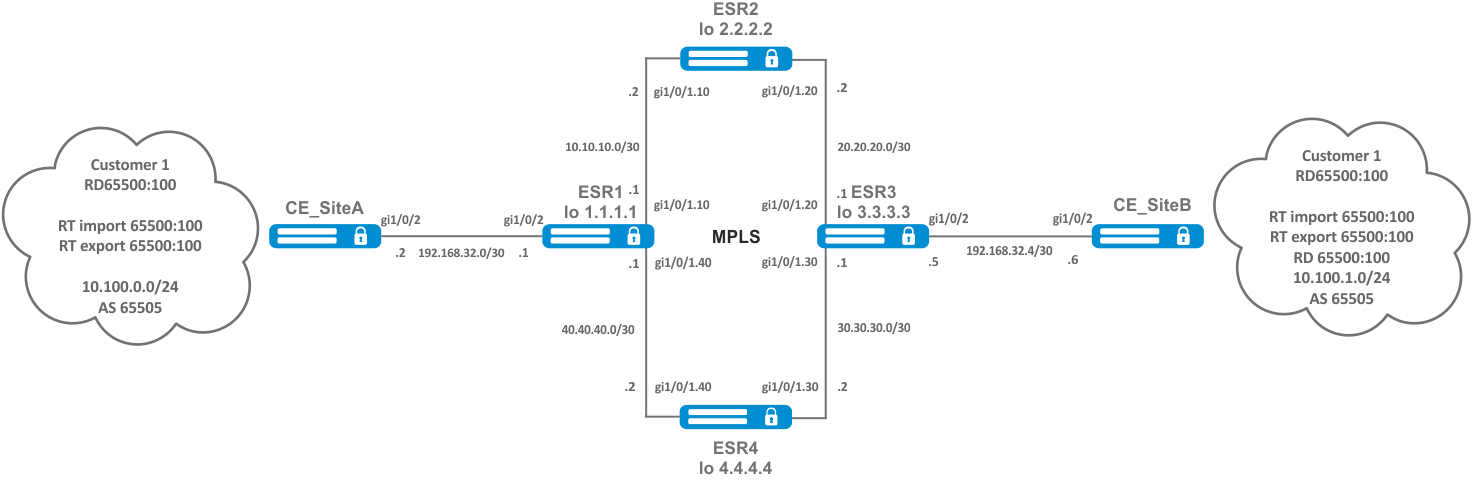
Objective:
Configure L3VPN based on MPLS technology between ESR1 and ESR3. The final result of the configuration is the appearance of connectivity between nodes connected to the VRF on different routers in the network (i.e. the union of VRFs on different routers via MPLS transport). In this case, transfer of MPLS service tags for L3VPN service via MP-BGP and transfer of transport tags to reach nexthop addresses of received BGP routes must be provided.
Solution:
Configuring addressing and enabling IGP on routers
ESR1
router ospf log-adjacency-changes
router ospf 1
  router-id 1.1.1.1
  area 0.0.0.0
    enable
  exit
  enable
exit

interface loopback 1
  ip address 1.1.1.1/32
  ip ospf instance 1
  ip ospf
exit

interface gigabitethernet 1/0/1.10
  ip firewall disable
  ip address 10.10.10.1/30
  ip ospf instance 1
  ip ospf
exit

interface gigabitethernet 1/0/1.40
  ip firewall disable
  ip address 40.40.40.1/30
  ip ospf instance 1
  ip ospf
exit

system jumbo-framesESR2
router ospf log-adjacency-changes
router ospf 1
  router-id 2.2.2.2
  area 0.0.0.0
    enable
  exit
  enable
exit

interface loopback 1
  ip address 2.2.2.2/32
  ip ospf instance 1
  ip ospf
exit

interface gigabitethernet 1/0/1.10
  ip firewall disable
  ip address 10.10.10.2/30
  ip ospf instance 1
  ip ospf
exit

interface gigabitethernet 1/0/1.20
  ip firewall disable
  ip address 20.20.20.2/30
  ip ospf instance 1
  ip ospf
exit

system jumbo-framesESR3
router ospf log-adjacency-changes
  router ospf 1
  router-id 3.3.3.3
  area 0.0.0.0
    enable
  exit
  enable
exit

interface loopback 1
  ip address 3.3.3.3/32
  ip ospf instance 1
  ip ospf
exit

interface gigabitethernet 1/0/1.20
  ip firewall disable
  ip address 20.20.20.1/30
  ip ospf instance 1
  ip ospf
exit

interface gigabitethernet 1/0/1.30
  ip firewall disable
  ip address 30.30.30.1/30
  ip ospf instance 1
  ip ospf
exit

system jumbo-framesESR4
router ospf log-adjacency-changes
router ospf 1
  router-id 4.4.4.4
  area 0.0.0.0
    enable
  exit
  enable
exit

interface loopback 1
  ip address 4.4.4.4/32
  ip ospf instance 1
  ip ospf
exit

interface gigabitethernet 1/0/1.40
  ip firewall disable
  ip address 40.40.40.2/30
  ip ospf instance 1
  ip ospf
exit

interface gigabitethernet 1/0/1.30
  ip firewall disable
  ip address 30.30.30.2/30
  ip ospf instance 1
  ip ospf
exit

system jumbo-framesIt is necessary to make sure that the protocol is running on every router.
ESR1# show ip ospf neighbors


Router ID        Pri  State          DTime  Interface      Router IP
---------        ---  -----          -----  -------------  ---------
2.2.2.2          128  Full/BDR       00:39  gi1/0/1.10     10.10.10.2
4.4.4.4          128  Full/BDR       00:32  gi1/0/1.40     40.40.40.2


ESR1# show ip ospf
O       40.40.40.0/30      	[150/10]          dev gi1/0/1.40                    [ospf1 1970-01-08]  (1.1.1.1)
O     * 30.30.30.0/30    	[150/20]          via 40.40.40.2 on gi1/0/1.40      [ospf1 1970-01-08]  (3.3.3.3)
O       1.1.1.1/32          [150/0]           dev lo1      						[ospf1 1970-01-08]  (1.1.1.1)
O     * 4.4.4.4/32          [150/10]          via 40.40.40.2 on gi1/0/1.40      [ospf1 1970-01-08]  (4.4.4.4)
O     * 20.20.20.0/30     	[150/20]          via 10.10.10.2 on gi1/0/1.10      [ospf1 22:05:45]  	(3.3.3.3)
O       10.10.10.0/30      	[150/10]          dev gi1/0/1.10                    [ospf1 22:05:33]  	(1.1.1.1)
O     * 3.3.3.3/32          [150/20]          multipath                         [ospf1 22:05:45]  	(3.3.3.3)
                            				  via 40.40.40.2 on gi1/0/1.40 weight 1
O * 2.2.2.2/32 [150/10] via 10.10.10.2 on gi1/0/1.10 [ospf1 22:05:45] (2.2.2.2)LDP configuration:
ESR1
mpls
  ldp
    address-family ipv4
      transport-address 1.1.1.1
      interface gigabitethernet 1/0/1.10
      exit
      interface gigabitethernet 1/0/1.40
      exit
    exit
    enable
  exit
  forwarding interface gigabitethernet 1/0/1.10
  forwarding interface gigabitethernet 1/0/1.40
exitESR2
mpls
  ldp
    address-family ipv4
      transport-address 2.2.2.2
      interface gigabitethernet 1/0/1.10
      exit
      interface gigabitethernet 1/0/1.20
      exit
    exit
    enable
  exit
  forwarding interface gigabitethernet 1/0/1.10
  forwarding interface gigabitethernet 1/0/1.20
exitESR3
mpls
  ldp
    address-family ipv4
      transport-address 3.3.3.3
      interface gigabitethernet 1/0/1.20
      exit
      interface gigabitethernet 1/0/1.30
      exit
    exit
    enable
  exit
  forwarding interface gigabitethernet 1/0/1.20
  forwarding interface gigabitethernet 1/0/1.30
exitESR4
mpls
  ldp
    address-family ipv4
      transport-address 4.4.4.4
      interface gigabitethernet 1/0/1.30
      exit
      interface gigabitethernet 1/0/1.40
      exit
    exit
    enable
  exit
  forwarding interface gigabitethernet 1/0/1.30
  forwarding interface gigabitethernet 1/0/1.40
exitOne of the following commands can be used to check the LDP convergence:
ESR1# show mpls ldp neighbor
Peer LDP ID: 2.2.2.2; Local LDP ID 1.1.1.1
	State: Operational
    TCP connection: 2.2.2.2:33933 - 1.1.1.1:646
    Messages sent/received: 1059/1070
    Uptime: 17:32:07
    LDP discovery sources:
        gigabitethernet 1/0/1.10
Peer LDP ID: 4.4.4.4; Local LDP ID 1.1.1.1
    State: Operational
    TCP connection: 4.4.4.4:40894 - 1.1.1.1:646
    Messages sent/received: 1376/1386
    Uptime: 22:38:38
    LDP discovery sources:
gigabitethernet 1/0/1.40MP-BGP configuration
Create VRF on ESR1 and ESR3, respectively. Specify RD, rt-export/import in accordance with our scheme.
Without specifying RD and RT attributes the route information will not get into the VPNv4 table.
ESR1
ESR1(config)# ip vrf Customer1
ESR1(config-vrf)# ip protocols bgp max-routes 1000
ESR1(config-vrf)# rd 65500:100
ESR1(config-vrf)# route-target import 65500:100
ESR1(config-vrf)# route-target export 65500:100ESR3
ESR3(config)# ip vrf Customer1
ESR3(config-vrf)# ip protocols bgp max-routes 1000
ESR3(config-vrf)# rd 65500:100
ESR3(config-vrf)# route-target export 65500:100
ESR3(config-vrf)# route-target import 65500:100
ESR3(config-vrf)# exitConfigure iBGP between ESR1 and ESR3. Enable extended community sending on both devices.
ESR1
ESR1(config)# router bgp log-neighbor-changes
ESR1(config)# router bgp 65500
ESR1(config-bgp)# router-id 1.1.1.1
ESR1(config-bgp)# enable
ESR1(config-bgp)# neighbor 3.3.3.3
ESR1(config-bgp-neighbor)# remote-as 65500
ESR1(config-bgp-neighbor)# update-source 1.1.1.1
ESR1(config-bgp-neighbor)# enable
ESR1(config-bgp-neighbor)# address-family ipv4 unicast
ESR1(config-bgp-neighbor-af)# enable
ESR1(config-bgp-neighbor-af)# exit
ESR1(config-bgp-neighbor)# address-family vpnv4 unicast
ESR1(config-bgp-neighbor-af)# send-community extended
ESR1(config-bgp-neighbor-af)# enable ESR3
ESR3(config)# router bgp log-neighbor-changes
ESR3(config)# router bgp 65500
ESR3(config-bgp)# router-id 3.3.3.3
ESR3(config-bgp)# enable
ESR3(config-bgp)# neighbor 1.1.1.1
ESR3(config-bgp-neighbor)# remote-as 65500
ESR3(config-bgp-neighbor)# update-source 3.3.3.3
ESR3(config-bgp-neighbor)# enable
ESR3(config-bgp-neighbor)# address-family ipv4 unicast
ESR3(config-bgp-neighbor-af)# enable
ESR3(config-bgp-neighbor-af)# exit
ESR3(config-bgp-neighbor)# address-family vpnv4 unicast
ESR3(config-bgp-neighbor-af)# send-community extended
ESR3(config-bgp-neighbor-af)# enableIt is necessary to make sure that BGP session is successfully established.
ESR1# show ip bgp neighbors
BGP neighbor is 3.3.3.3
    BGP state: Established
    Neighbor address: 3.3.3.3
    Neighbor AS: 65500
    Neighbor ID: 3.3.3.3
    Neighbor caps: refresh enhanced-refresh restart-aware AS4
    Session: internal multihop AS4
    Source address: 1.1.1.1
    Weight: 0
    Hold timer: 126/180
    Keepalive timer: 40/60
    Address family ipv4 unicast:
    Default originate: No
    Default information originate: No
Uptime: 88495 sPE-CE routing configuration
Customer1 advertises a BGP(AS65505) subnet 10.100.0.0/24. Configure eBGP session between CE_SiteA and PE.
By default: the route advertising is prohibited for EBGP, you should configure an allow rule; for IBGP route advertising is allowed.
CE_SiteA
Configure the corresponding interfaces. Also create a route-map in which we specify the subnets allowed to be advertised.
CE _SiteA
interface gigabitethernet 1/0/2
  ip firewall disable
  ip address 192.168.32.2/30
exit

interface loopback 1
  ip address 10.100.0.1/24
exit

route-map OUTPUT
  rule 1
    match ip address 10.100.0.0/24
    action permit
  exit
exitConfigure eBGP between ESR1 and CE_SiteA.
CE_SiteA
router bgp log-neighbor-changes
router bgp 65505
  router-id 192.168.32.1
  neighbor 192.168.32.1
    remote-as 65500
    allow-local-as 1
    update-source 192.168.32.2
    address-family ipv4 unicast
      route-map OUTPUT out
      enable
    exit
    enable
  exit
  address-family ipv4 unicast
    network 10.100.0.0/24
    exit
enableESR1
Configure interface to the CE direction. Also create a route-map in which we specify the subnets allowed to be advertised.
ESR1
interface gigabitethernet 1/0/2
  ip vrf forwarding Customer1
  description "Customer1"
  ip firewall disable
  ip address 192.168.32.1/30

Создаем route-map

route-map OUTPUT
  rule 1
    action permit
  exit
exitConfigure eBGP between ESR1 and CE_SiteA.
ESR1
router bgp 65500
  vrf Customer1
    router-id 192.168.32.1
    neighbor 192.168.32.2
    remote-as 65505
    update-source 192.168.32.1
    address-family ipv4 unicast
  exit
exitAllow BGP routes to be transmitted to the peer.
ESR1
  route-map OUTPUT out
    enable
  exit
  enable
exit
Allow forwarding routes from VRF to the VPNv4 unicast table
ESR1
address-family ipv4 unicast
redistribute connected
redistribute bgp 65500
exit
enable
exit The following commands can be used to check the accepted and advertised routes:
ESR1# show ip bgp 65500 vrf Customer1 neighbors 192.168.32.2 advertise-routes
Status codes: u - unicast, b - broadcast, m - multicast, a - anycast
              * - valid, > - best
Origin codes: i - IGP, e - EGP, ? - incomplete


     Network              Next Hop             Metric  LocPrf      Weight Path
*> u 10.100.1.0/24        192.168.32.1                 100                65500 i
*> u 192.168.32.4/30 192.168.32.1 100 65500 iDisplay the advertised routes for a specific peer. The route information is displayed after the filtering is applied.
ESR1# show ip bgp 65500 vrf Customer1 neighbors 192.168.32.2 routes
Status codes: u - unicast, b - broadcast, m - multicast, a - anycast
              * - valid, > - best
Origin codes: i - IGP, e - EGP, ? - incomplete


     Network              Next Hop             Metric  LocPrf      Weight Path
*> u 10.100.0.0/24 192.168.32.2 100 0 65505Outputs the received route information from a specific peer. The route information is displayed after the filtering is applied.
CE_SiteB
Configure the corresponding interfaces.
CE_SiteB
interface gigabitethernet 1/0/2
ip firewall disable
ip address 192.168.32.6/30
exit

interface loopback 1
ip address 10.100.1.1/24
exit

route-map OUTPUT
rule 1
match ip address 10.100.1.0/24
action permit
Configure eBGP between ESR3 and CE_SiteB.
CE_SiteB
router bgp 65505
router-id 192.168.32.6
neighbor 192.168.32.5
remote-as 65500
allow-local-as 1
update-source 192.168.32.6
address-family ipv4 unicast
route-map OUTPUT out
enable
exit
enable
exit
address-family ipv4 unicast
network 10.100.1.0/24
exit
enableESR3
Configure interface to the CE direction.
ESR3
interface gigabitethernet 1/0/2
ip vrf forwarding Customer1
description "Customer1"
ip firewall disable
ip address 192.168.32.5/30Create a route-map in which we specify the subnets allowed to be advertised.
ESR3
route-map OUTPUT
rule 1
action permitConfigure eBGP between ESR3 and CE_SiteB.
ESR3
router bgp 65500
vrf Customer1
router-id 192.168.32.5
neighbor 192.168.32.6
remote-as 65505
update-source 192.168.32.5
address-family ipv4 unicast
Allow BGP routes to be transmitted to the peer.
ESR3
route-map OUTPUT out
enable
exit
enable
exitAllow route forwarding from VRF to VPNV4 for address-family IPv4.
ESR3
address-family ipv4 unicast
redistribute connected
redistribute bgp 65500
exit
enable
exitYou can use one of the following commands to view the VPNv4 table:
ESR1# show ip bgp vpnv4 unicast all
Status codes: * - valid, > - best, i - internal, S - stale
Origin codes: i - IGP, e - EGP, ? - incomplete


Codes Route Distinguisher   IP Prefix          Next hop        Metric     Label   LocPrf     Weight Path
----- --------------------- ------------------ --------------- ---------- ------- ---------- ------ ----------------
*>    65500:100            	10.100.0.0/24      --              --         23      --         --     ?
*>i   65500:100            	192.168.32.4/30    3.3.3.3         --         84      100        0      i
*>i 65500:100 10.100.1.0/24 3.3.3.3 -- 84 100 0 iOutputs all accepted VPNv4 routes after applying filtering.
MPLS traffic balancing
ESR routers have a multi-core architecture. One of the first links in processing incoming traffic is the load balancer daemon (lbd), which performs two main functions:
1) Distributes the load evenly among all router CPUs.
2) Detects abnormal situations with high load on some CPUs, and redistributes processing from these CPUs to less loaded ones.
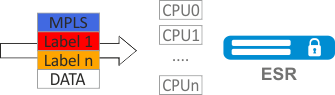
By default, lbd uses only MPLS tags to calculate the hash and then distribute the load to the different CPUs. This behavior is not always an advantage, especially when there are "large" homogeneous streams of MPLS traffic. Additional functionality can be included to add entropy to the hash:
cpu load-balance mpls passenger ip
Enables the possibility to "look beyond" the MPLS header to find the IP header, and add ip-src and ip-dst to the hash calculation.
cpu load-balance mpls passenger ip-over-ethernet-pseudowire-with-cw
cpu load-balance mpls passenger ip-over-ethernet-pseudowire-without-cw
Allows to explicitly specify whether Control Word functionality is used when building L2VPN. Allows to prevent an error occurring when a package with Control Word present can be mistakenly recognized as a package without Control Word.
Configuration example
Objective:
Enable L2VPN traffic balancing without using Control Word functionality.
Solution:
ESR
ESR(config)# system cpu load-balance mpls passenger ip
ESR(config)# system cpu load-balance mpls passenger ipoe-pw-without-cw
Operation with the bridge domain within MPLS
To organize L2VPN service, you need to configure a bridge domain on the device, create the required AC, PW (LDP-signaling) and include all the necessary elements in this bridge domain.
For point-to-point, a bridge domain is created automatically.
Traffic is switched between elements of the bridge domain based on the listed rules:
- A MAC address table is automatically created for each bridge domain, similar to Ethernet switches. Ethernet frames are switched based on analysis of the destination MAC address (DST MAC).
- Frames with a known DST MAC will be sent to the appropriate AC/PW.
- Frames with unknown DST MAC, broadcast- and multicast-frames (so called BUM traffic, "Broadcast, Unknown unicast and Multicast") will be sent to all elements of the bridge domain, except for the element (AC or PW) from which you entered the bridge domain.
- Switching takes into account the DST MAC in the frames, but does not take into account the VLAN tags present on the frames — thus, switching within a bridge domain is not "VLAN-aware".
In the current implementation, the bridge domain does not allow traffic of data link layer protocols such as STP, LLDP, CDP, etc.
The bridge domain can operate in two transport modes: ethernet or vlan. Transport mode sets the rules for handling traffic to and from the bridge domain.
In LDP signaling, ethernet mode (Raw mode, type 5) is used by default. A transport mode can be set for each individual VPLS instance.
In BGP signaling, the bridge domain only operate in ethernet mode.
PE1# config
PE1(config)# mpls
PE1(config-mpls)# l2vpn
PE1(config-l2vpn)# vpls MARTINI_br
PE1(config-l2vpn-vpls)# transport-mode vlan

PE1# sh mpls l2vpn pseudowire
Neighbor                                PW ID      Sig Type       Status
--------------------------------------- ---------- --- ---------- ------
10.10.0.2 200 LDP Eth Tagged Up In LDP signaling, the transport mode is matched between PEs during pseudowire creation, so it must match on both PEs.
Рассмотрим правила обработки трафика:
1. Ethernet (Raw) mode:
- If AC is a subinterface, the vlan tag is removed before putting it in the bridge. Upon leaving the bridge, the vlan tag is restored.
- If AC is an interface, then tagged and untagged traffic flows in both directions without modification.
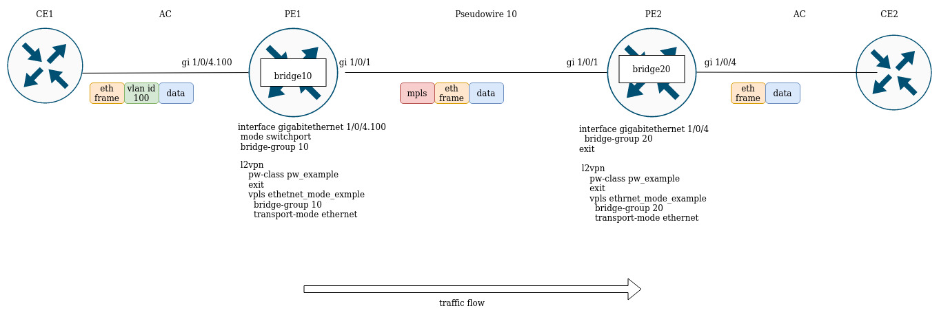
Suppose PE1 and PE2 are configured in ethernet mode (Figure 2). On the PE1 side, gigabitethernet 1/0/4.100 subinterface is included in the bridge domain, so the vlan tag (vlan id 100) from incoming traffic will be removed before being placed in Pseudowire 10 (respectively, restored when traffic to the AC side). On the other side the AC on PE2, is an interface, which means that traffic will pass through without modification in either direction.
2. Vlan (Tagged) mode:
- If AC is a subinterface, the vlan tag is saved before putting it in the bridge. The vlan tag can be saved or overwritten depending on the configuration when you exit the bridge.
- If AC is an interface, traffic modification does not occur in either direction.
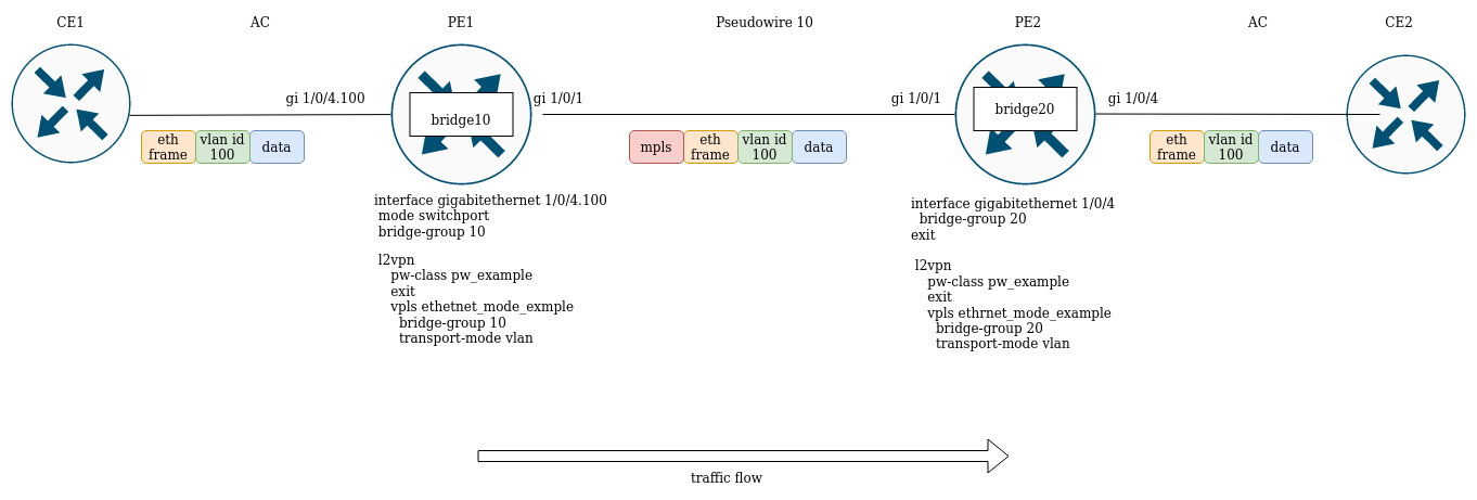
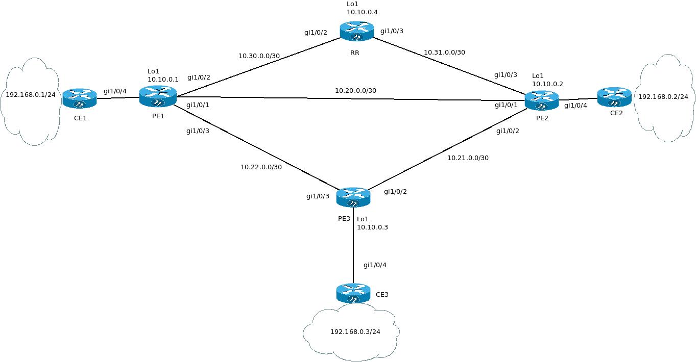
Assignment of MTU when operating with MPLS
It is very important to correctly configure the MTU parameter on the interfaces through which a packet is transmitted. This is true for the installation of the pseudowire and for the transmission of service traffic.
First of all, the MTU value is involved in signaling when constructing a pseudowire in both LDP-signaling and BGP-signaling. In LDP-signaling, the MTU is set within the pw — class setting:
For signaling (LDP, BGP) the default MTU value is 1500.
The MTU values involved in signaling do not affect the actual packet size passing through the pseudowire.
LDP-signaling. Configuration of MTU for matching
PE2(config)# mpls
PE2(config-mpls)# l2vpn
PE2(config-l2vpn)# pw-class MTU_example
PE2(config-l2vpn-pw-class)# encapsulation mpls mtu 9000
PE2(config-l2vpn-pw-class)# exit
PE2(config-mpls)# l2vpn
PE2(config-l2vpn)# vpls MTU_Example_PW
PE2(config-l2vpn-vpls)# pw 200 10.10.0.1
PE2(config-l2vpn-pw)# pw-class
PE2(config-l2vpn-pw)# pw-class MTU_example

*Просмотр созданных pw-class'ов*
PE2#  sh mpls l2vpn pw-class
PW-class                         Neighbor   PW ID      Status Status-tlv MTU
-------------------------------- ---------- ---------- ------ ---------- ------
MTU_example                       10.10.0.1  200        Up     Enable     9000


PE2# sh mpls l2vpn vpls  MTU_Example_PW
VPLS:  MTU_Example_PW
...
    PWs:
      PW ID 2, Neighbor 10.10.0.1:
        MTU:         9000
        Last change: 01:27:42
        Status:      Up

* Для сигнализации PW 2 данного VPLS выбрано MTU 9000* Consider the example:
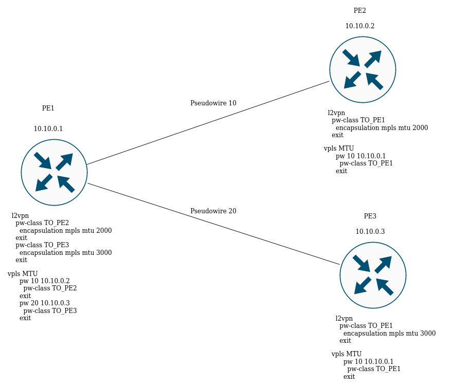
In the figure above, PE1 raises two pseudowires: Pseudowire 10 to PE2, and Pseudowire 20 to PE3 respectively. For signaling with PE2 the MTU will be set to 2000 (pw-class TO_PE2), for PE3 the MTU will be 3000 (pw-class TO_PE3).
For BGP-signaling the MTU parameter can also be specified:
BGP -signaling. Configuration of MTU for matching
PE1(config)# mpls
PE1(config-mpls)# l2vpn
PE1(config-l2vpn)# vpls l2vpn_MTU
PE1(config-l2vpn-vpls)# autodiscovery bgp
PE1(config-bgp)# mtu 1500

PE2# sh mpls l2vpn vpls  l2vpn_MTU
VPLS: l2vpn_MTU
...
    PWs:
      PW ID 2, Neighbor 10.10.0.1:
        MTU:         1500
        Last change: 01:27:42
        Status:      Up

* The MTU 1500 will be selected for signaling all pseudowires of this VPLS *If the MTU value is different when matching, the status of the pseudowire will be "DOWN", "Reason : MTU mismatch".
PE1(config-l2vpn)# vpls l2vpn_MTU
PE1(config-l2vpn-vpls)# autodiscovery bgp
PE1(config-bgp)# mtu 2000

PE2# sh mpls l2vpn vpls l2vpn_MTU
...
    PWs:
      PW ID 2, Neighbor 10.10.0.1:
        MTU:         2000
        Last change: 00:00:10
        Status:      Down
        Reason:      MTU mismatch
When configuring VPLS (BGP-signaling), you can disable MTU checking when creating pseudowires:
PE1(config)# mpls
PE1(config-mpls)# l2vpn
PE1(config-l2vpn)# vpls l2vpn _MTU
PE1(config-l2vpn-vpls)# autodiscovery bgp
PE1(config-bgp)# ignore mtu-mismatchNow, when matching, the MTU value will be ignored.
By default, the bridge domain has an MTU of 1500 bytes. It is worth noting that bridge-domain automatically selects the lowest MTU value based on its own MTU and the MTU of the interfaces included in the bridge-domain.
* E.g., we have a bridge domain 100, which includes interfaces gi1/0/1 with MTU value 2000, and gi1/0/2 with MTU value 3000 *
CE3(config)# bridge 100
CE3(config-bridge)# enable
CE3(config-bridge)# exit
CE3(config)# interface gigabitethernet 1/0/1
CE3(config-if-gi)# mtu 2000
CE3(config-if-gi)# bridge-group 100
CE3(config-if-gi)# exit
CE3(config)# interface gigabitethernet 1/0/2
CE3(config-if-gi)# mtu 3000
CE3(config-if-gi)# bridge-group 100
CE3(config-if-gi)# do com

* The MTU of the bridge domain will be 1500, since the bridge itself has a default MTU of 1500 (the default value), which has become the lowest:
 MTU bridge 100 = 1500  <-- The lowest MTU value
 MTU gi1/0/1  = 2000
 MTU gi1/0/2 = 3000
*


CE3# sh interfaces bridge
Bridges      Interfaces
----------   --------------------------------------------------------------
bridge 100   gi1/0/1-2

CE3# sh interfaces status bridge 100
Interface 'bridge 100' status information:
 Description:          --
 Operational state:    UP
 Administrative state: Up
 Supports broadcast:   Yes
 Supports multicast:   Yes
 MTU:                  1500
 MAC address:          a8:f9:4b:aa:11:00
 Last change:          1 minute and 46 seconds
 Mode:                 Routerport

* Change the MTU on the bridge domain itself: *

CE3(config)# bridge 100
CE3(config-bridge)# mtu 6000
CE3(config-bridge)# do com

* The MTU of the bridge domain became 2000 bytes, because gi1/0/2 has the lowest MTU:
 MTU bridge 100 = 6000
 MTU gi1/0/1  = 2000 <-- The lowest MTU value
 MTU gi1/0/2 = 3000
*

CE3# sh interfaces bridge
Bridges      Interfaces
----------   --------------------------------------------------------------
bridge 100   gi1/0/1-2

CE3# sh interfaces status bridge 100
Interface 'bridge 100' status information:
 Description:          --
 Operational state:    Up
 Administrative state: Up
 Supports broadcast:   Yes
 Supports multicast:   Yes
 MTU:                  2000
 MAC address:          a8:f9:4b:aa:11:00
 Last change:          6 minutes and 42 seconds
 Mode:                 Routerport
Consider the example of traffic passing through the L2VPN service:
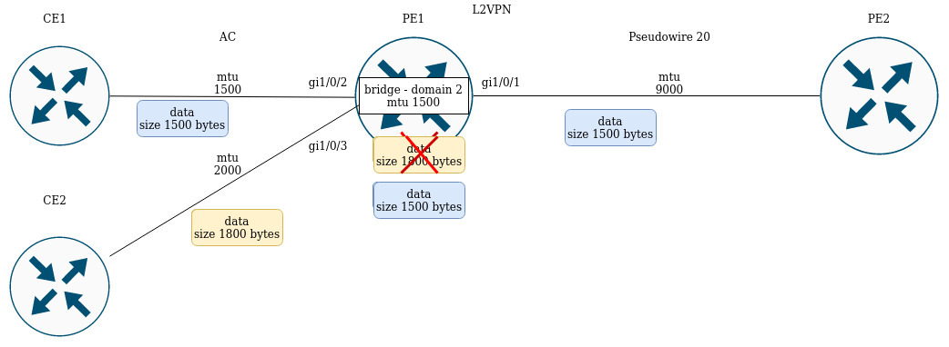
PE1 has the following MTU values on the interfaces:
PE1# sh interfaces status
Interface            Admin   Link    MTU      MAC address          Last change                 Mode
                     state   state
------------------   -----   -----   ------   ------------------   -------------------------   ----------
gi1/0/1              Up      Up      9000     a8:f9:4b:ac:4d:16    5 hours, 25 minutes and 2   Routerport
                                                                   seconds

gi1/0/2              Up      Up      1500     a8:f9:4b:ac:4d:17    4 days, 4 hours, 49         Switchport
                                                                   minutes and 40 seconds

gi1/0/3              Up      Up      1800     a8:f9:4b:ac:4d:18    4 days, 1 hour, 49          Switchport
                                                                   minutes and 38 seconds

bridge 2             Up      Up      1500     a8:f9:4b:ac:4d:15    1 day, 1 hour, 27 minutes   Routerport
                                                                   and 28 seconds
CE1 sends packets of 1500 bytes, CE2 sends packets of 1800 bytes respectively. Since the MTU of the bridge domain is smaller than the MTU of the packet from CE2, the packet from CE2 will be discarded before hitting the bridge domain. Similar will be the case if the MTU interface facing the mpls-core (gi1/0/1) is less than the MTU coming from the CE packets (taking into account the mpls header).
Similar behavior when passing traffic in the L3VPN service:
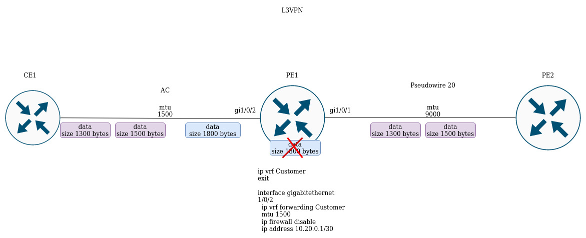
If CE1 sends a packet with a higher MTU than on the interface facing the client (gi1/0/2) or towards the mpls-core (gi1/0/1), the packet will be discarded.