Interface management. Firmware version 1.13.0
VLAN Configuration
VLAN ( Virtual Local Area Network) is a logical (virtual) local area network that represents a group of devices, which communicate on channel level regardless of their physical location. VLAN operation is based on the use of additional Ethernet header fields according to 802.1q standard. In fact, VLAN isolates the broadcast domain by limiting the switching of only those Ethernet frames which have the same VLAN-ID in the Ethernet header.
Configuration algorithm
Step | Description | Command | Keys |
|---|---|---|---|
1 | Create VLAN | esr(config)# vlan <VID> | <VID> – VLAN identifier, set in the range of [2..4094]. It is also possible to create multiple vlan (comma separated), vlan range (hyphen separated) or combined entry containing commas and hyphens. |
2 | Specify vlan name (optionally) | esr(config-vlan)# name <vlan-name> | <vlan-name> – up to 255 characters. |
3 | Disable monitoring of the status of interfaces on which processing of the given VLAN Ethernet frames is allowed (optional). | esr(config-vlan)# force-up | |
4 | Disable the processing of incoming untagged Ethernet frames based on the default VLAN's switching table (VLAN-ID – 1) (optional). | esr(config-if-gi)# no switchport forbidden default-vlan | |
5 | Set L2 interface operation mode. | esr(config-if-gi)# mode switchport | |
6 | Set the combined mode of the physical interface. | esr(config-if-gi)# mode hybrid | Only for ESR-1000/1200/1500/1511/1700 |
7 | Set L2 interface operation mode. | esr(config-if-gi)# switchport access | Only for ESR-10/12V(F)/14VF/20/21/100/200/3100. This mode is the default mode and is not displayed in the configuration. |
esr(config-if-gi)# switchport trunk | Only for ESR-10/12V(F)/14VF/20/21/100/200/3100. | ||
esr(config-gi)# switchport general | Only for ESR-1000/1200/1500/1511/1700. This mode is the default mode and is not displayed in the configuration. | ||
8 | Configure VLAN list on the interface in tagged mode | esr(config-if-gi)# switchport trunk allowed vlan add <VID> | For ESR-10/12V(F)/14VF/20/21/100/200/3100. <VID> – VLAN identifier, set in the range of [2..4094]. |
esr(config-if-gi)# switchport general allowed vlan add <VID> tagged | For ESR-1000/1200/1500/1511/1700. <VID> – VLAN identifier, set in the range of [2..4094]. | ||
9 | Configure VLAN on the interface in tagged mode (optionally) | esr(config-if-gi)# switchport trunk native-vlan <VID> | For ESR-10/12V(F)/14VF/20/21/100/200/3100. <VID> – VLAN identifier, set in the range of [2..4094]. |
esr(config-if-gi)# switchport general allowed vlan add <VID> untagged | For ESR-1000/1200/1500/1511/1700. <VID> – VLAN identifier, set in the range of [2..4094]. | ||
10 | Enable the processing of Ethernet frames of all created VLANs on the interface (optionally) | esr(config-if-gi)# switchport trunk allowed vlan auto-all | Only for ESR-10/12V(F)/14VF/20/21/100/200/3100. |
esr(config-if-gi)# switchport general allowed vlan auto-all | Only for ESR-1000/1200/1500/1511/1700. |
Configuration example 1. VLAN removal from the interface
Objective:
On the basis of the factory configuration, remove gi1/0/1 port from VLAN 2.

Solution:
Remove VLAN2 from gi1/0/1 port:
esr(config)# interface gi 1/0/1
esr(config-if-gi)# switchport general allowed vlan remove 2 untagged
esr(config-if-gi)# no switchport general pvid Configuration example 2. Enabling VLAN processing in tagged mode
Objective:
Configure gi1/0/1 and gi1/0/2 ports for packet transmission and reception in VLAN 2, VLAN 64, VLAN 2000.
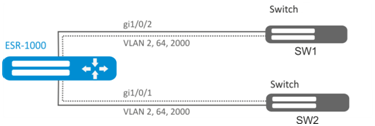
Solution:
Create VLAN 2, VLAN 64, VLAN 2000 on ESR-1000:
esr-1000(config)# vlan 2,64,2000 Specify VLAN 2, VLAN 64, VLAN 2000 for gi1/0/1-2 port:
esr-1000(config)# interface gi1/0/1
esr-1000(config-if-gi)# mode switchport
esr-1000(config-if-gi)# switchport forbidden default-vlan
esr-1000(config-if-gi)# switchport general allowed vlan add 2,64,2000 taggedConfiguration example 3. Enabling VLAN processing in tagged and untagged modes
Objective:
Configure gi1/0/1 ports for packet transmission and reception in VLAN 2, VLAN 64, VLAN 2000 in trunk mode, configure gi1/0/2 port in access mode for VLAN 2 on ESR-100/ESR -200.
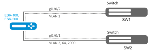
Solution:
Create VLAN 2, VLAN 64, VLAN 2000 on ESR-100/ESR-200:
esr(config)# vlan 2,64,2000Specify VLAN 2, VLAN 64, VLAN 2000 for gi1/0/1 port:
esr(config)# interface gi1/0/1
esr(config-if-gi)# mode switchport
esr(config-if-gi)# switchport forbidden default-vlan
esr(config-if-gi)# switchport mode trunk
esr(config-if-gi)# switchport trunk allowed vlan add 2,64,2000 Specify VLAN2 to gi1/0/2 port:
esr(config)# interface gi1/0/2
esr(config-if-gi)# mode switchport
esr(config-if-gi)# switchport access vlan 2LLDP configuration
Link Layer Discovery Protocol (LLDP) is a data link layer protocol allowing network equipment to notify the devices operating in a local network of its existence and to transmit parameters to it as well as to receive similar information.
Configuration algorithm
Step | Description | Command | Keys |
|---|---|---|---|
1 | Enable LLDP on the router. | esr(config)# lldp enable | |
2 | Enable the LLDPDU receiving and proceeding on the physical interface. | esr(config-if-gi)# lldp receive | |
3 | Enable LLDPDU transmission on the physical interface. | esr(config-if-gi)# lldp transmit | |
8 | Set the LLDPDU sending period (optionally). | esr(config)# lldp timer <SEC> | <SEC> – time interval in seconds, takes values of [1..32768]. Default value: 30 |
4 | Set the period during which the router keeps the information received via LLDP (optionally) | esr(config)# lldp hold-multiplier <SEC> | <SEC> – time interval in seconds, takes values of [1..10]. Default value: 4 |
5 | Set IP address which will be transmitted to LLDP TLV as the management-address (optionally). | esr(config)# lldp management-address <ADDR> | <ADDR> – IP address, defined as AAA.BBB.CCC.DDD where each part takes values of [0..255]. One of the existent is set by default |
6 | Set the system-description field which will be transmitted to LLDP TLV as the system-description (optionally). | esr(config)# lldp system-description <DESCRIPTION> | <DESCRIPTION> – system description, set by the string of up to 255 characters. By default contains the information of the router model and firmware version. |
7 | Set the system-name field which will be transmitted to LLDP TLV as the system-name (optionally). | esr(config)# lldp system-name <NAME> | <NAME> – system name, set by the string of up to 255 characters. By default coincides with the specified hostname |
Configuration example
Objective:
Organize the LLDPDU exchange and proceeding between ESR-1 and ESR-2 routers.

Solution:
R1 configuration
Enable LLDP globally on the router:esr(config)# lldp enableCODEEnable the receiving and transmission of LLDPDU on the gi 1/0/1 interface.
esr(config)# interface gigabitethernet 1/0/1 esr(config-if-gi)# lldp receive esr(config-if-gi)# lldp transmitCODER2 configuration
Enable LLDP globally on the router:
esr(config)# lldp enableCODEEnable the receiving and transmission of LLDPDU on the gi 1/0/1 interface.
esr(config)# interface gigabitethernet 1/0/1 esr(config-if-gi)# lldp receive esr(config-if-gi)# lldp transmitCODETo view LLDP neighbors information, use the following command:
esr# show lldp neighborsCODETo view more detailed information on the certain interface neighbor, use the following command:
esr# show lldp neighbors gigabitethernet 1/0/1CODETo view LLDP statistics, use the following command:
esr# show lldp statisticsCODE
LLDP MED configuration
LLDP MED — LLDP standard enhancement which allows to transmit network policies: VLAN ID, DSCP, priority.
Configuration algorithm
Step | Description | Command | Keys |
|---|---|---|---|
1 | Enable LLDP on the router | esr(config)# lldp enable | |
2 | Enable LLDPDU transmission on the physical interface. | esr(config-if-gi)# lldp transmit | |
3 | Enable MED LLDP enhancement on the router | esr(config)# lldp med fast-start enable | |
4 | Create network policy. | esr(config)# network-policy <NAME> | <NAME> – network-policy name, set by the string of up to 31 characters. |
5 | Specify the application type. | esr(config-net-policy)# application <APP_TYPE> | <APP-TYPE> – type of the application for which network-policy will be enabled. Takes the following values:
|
6 | Set the DSCP value (optional). | esr(config-net-policy)# dscp <DSCP> | <DSCP> – DSCP code value, takes values in the range of [0..63]. |
7 | Set the CoS value (optional). | esr(config-net-policy)# priority <PRIORITY> | <COS> – priority value, takes the following values:
|
8 | Set VLAN ID value. | esr(config-net-policy)# vlan <VID> [tagged] | <VID> – VLAN ID, takes values of [1..4094];
|
9 | Set a network policy on the interface. | esr(config-if-gi)# lldp network-policy <NAME> | <NAME> – network-policy name, set by the string of up to 31 characters. |
Voice VLAN configuration example
Voice VLAN — VLAN ID, in receiving of which an IP phone switches to the trunk mode with the specified VLAN ID for VoIP traffic reception and transmission. VLAN ID transmission is performed by LLDP MED enhancement.
Objective:
VoIP traffic and data traffic should be grouped in different VLANs - vid 10 for data and vid 20 for VoIP - and the sending of Voice VLAN from the gi 1/0/1 ESR port should be configured. Voice VLAN should be supported and enabled on the IP phone.

Solution:
First create VLAN 10 and 20 and configure the gi 1/0/1 interface in the trunk mode:
esr(config)# vlan 10,20
esr(config-vlan)# exit
esr(config)# interface gigabitethernet 1/0/1
esr(config-if-gi)# mode switchport
esr(config-if-gi)# switchport mode trunk
esr(config-if-gi)# switchport trunk allowed vlan add 10,20
esr(config-if-gi)# exitEnable LLDP and MED capability in LLDP globally on the router:
esr(config)# lldp enable
esr(config)# lldp med fast-start enableCreate and configure network policy in the way that VLAN ID 20 is specified for the voice application:
esr(config)# network-policy VOICE_VLAN
esr(config-net-policy)# application voice
esr(config-net-policy)# vlan 20 tagged
esr(config-net-policy)# exitConfigure LLDP on the interface and set a network policy:
esr(config)# interface gigabitethernet 1/0/1
esr(config-if-gi)# lldp transmit
esr(config-if-gi)# lldp receive
esr(config-if-gi)# lldp network-policy VOICE_VLAN
esr(config-if-gi)# exitSub-interface termination configuration
To terminate Ethernet frames of a certain VLAN on a specific physical interface, you need to create a sub-interface with the number of VLAN, frames of which will be terminated. When creating two sub-interfaces having the same VLAN but located on different physical/aggregated interfaces, switching of Ethernet frames between these sub-interfaces will not be possible as external segments will be separate broadcast domains. For data exchange between subscribers of different sub-interfaces (even with the same VLAN-ID) routing will be used, i.e. data exchange will occur at the third level of the OSI model.
Configuration algorithm
Step | Description | Command | Keys |
|---|---|---|---|
1 | Create a sub-interface of a physical interface (possible if the physical interface is in routeport or hybrid mode). | esr(config)# interface gigabitethernet <PORT>.<S-VLAN> or interface tengigabitethernet <PORT>.<S-VLAN> or interface port-channel <CH>.<S-VLAN> | <PORT> – physical interface number. <CH> – aggregated interface number. <S-VLAN> – identifier of created S-VLAN. If a physical interface is included in bridge-group, it will be impossible to create sub-interface. |
2 | Specify sub-interface description (optionally). | esr(config-subif)# description <DESCRIPTION> | <DESCRIPTION> – interface description, set by the string of up to 255 characters. |
3 | Specify VRF instance, in which the given sub-interface will operate (optionally). | esr(config-subif)# ip vrf forwarding <VRF> | <VRF> – VRF name, set by the string of up to 31 characters. |
4 | Specify the IPv4/IPv6 address and subnet mask for the interface to be configured or enable IP address obtain dynamically. | esr(config-subif)# ip address <ADDR/LEN> | <ADDR/LEN> – IP address and subnet mask length, defined as AAA.BBB.CCC.DDD/EE where each part AAA-DDD takes values of [0..255] and EE takes values of [1..32]. For advanced IPv4 addressing features see section IP addressing configuration. |
esr(config-subif)# ipv6 address <IPV6-ADDR/LEN> | <IPV6-ADDR/LEN> – IP address and prefix of a subnet, defined as X:X:X:X::X/EE where each X part takes values in hexadecimal format [0..FFFF] and EE takes values of [1..128]. You can specify several IPv4/IPv6 addresses separated by commas. Up to 8 IPv4/IPv6 addresses can be assigned to the interface. | ||
esr(config-subif)# ip address dhcp | For advanced DHCP client operation features, see section DHCP Client management. | ||
5 | Disable the Firewall features on the interface or enable the interface in the security zone (see Firewall configuration). | esr(config-subif)# ip firewall disable | |
esr(config-subif)# security-zone <NAME> | <NAME> – security zone name, set by the string of up to 31 characters. | ||
6 | Set the time interval during which statistics on the sub-interface load is collected. (optionally). | esr(config-subif)# load-average <TIME> | <TIME> – interval in seconds, takes values of [5..150]. |
7 | Set the lifetime of IPv4/IPv6 entries in the ARP table studied on the given interface (optionally). | esr(config-subif)# ip arp reachable-time <TIME> or esr(config-subif)# ipv6 nd reachable-time <TIME> | <TIME> – lifetime of dynamic MAC addresses, in milliseconds. Allowed values are from 5000 to 100000000 milliseconds. Real time of the entry update varies from [0,5;1,5]*<TIME>. |
8 | Change MTU (MaximumTransmitionUnit) size. MTU above 1500 will be active only when using the «system jumbo-frames» command (optional). | esr(config-subif)# mtu <MTU> | <MTU> – MTU value in bytes. Default value: 1500. |
9 | Enable recording of the current interface usage statistics (optional). | esr(config-subif)# history statistics | |
10 | Override the MSS (Maximum segment size) field in incoming TCP packets (optional). | esr(config-subif)# ip tcp adjust-mss <MSS> esr(config-subif)# ipv6 tcp adjust-mss <MSS> | <MSS> – MSS value, takes values in the range of [500..1460]. Default value: 1460 |
It is also possible to configure the sub-interface:
| |||
Sub-interface configuration example
Objective:
Configure subnet 192.168.3.1/24 in VLAN: 828 on the physical interface gigabitethernet 1/0/1.
Solution:
Create sub-interface for VLAN: 828
esr(config)# interface gigabitethernet 1/0/1.828Configure IP address from necessary subnet.
esr(config)# interface gigabitethernet 1/0/1.828
esr(config-subif)# ip address 192.168.3.1/24
esr(config-subif)# exitIn addition to assigning an IP address, you must either disable the firewall or configure the corresponding security zone on the sub interface.
Q-in-Q termination configuration
Q-in-Q is a technology of packet transmission with two 802.1q tags. The technology is used for extending quantity of VLANs in data networks. 802.1q header, which is closer to payload, is an Inner Tag. also known as C-VLAN (Customer VLAN). 802.1q header, which is comes before C-VLAN, is an Outer Tag also known as S-VLAN (Service VLAN). Using of double tags in Ethernet frames is describing by 802.1ad protocol.
Configuration algorithm
Step | Description | Command | Keys |
|---|---|---|---|
1 | Create a sub-interface of a physical interface (possible if the physical interface is in routeport or hybrid mode). | esr(config)# interface gigabitethernet <PORT>.<S-VLAN> or interface tengigabitethernet <PORT>.<S-VLAN> or interface port-channel <CH>.<S-VLAN> | <PORT> – physical interface number. <CH> – aggregated interface number. <S-VLAN> – identifier of created S-VLAN. If a physical interface is included in bridge-group, it will be impossible to create sub-interface. |
2 | Create Q-in-Q interface. | esr(config)# interface gigabitethernet <PORT>.<S-VLAN>.<C-VLAN> or esr(config)# interface tengigabitethernet <PORT>.<S-VLAN>.<C-VLAN> or esr(config)# interface port-channel <CH>.<S-VLAN>.<C-VLAN> | <PORT> – physical interface number. <CH> – aggregated interface number. <S-VLAN> – identifier of created S-VLAN. <C-VLAN> – identifier of created C-VLAN. If a physical interface or a sub-interface is included in bridge-group, it will be impossible to create sub-interface. |
3 | Specify Q-in-Q interface description (optionally). | esr(config-qinq-if)# description <DESCRIPTION> | <DESCRIPTION> – interface description, set by the string of up to 255 characters. |
4 | Specify VRF instance, in which the given Q-in-Q interface will operate (optionally). | esr(config-qinq-if) # ip vrf forwarding <VRF> | <VRF> – VRF name, set by the string of up to 31 characters. |
5 | Specify the IPv4/IPv6 address and subnet mask for the interface to be configured or enable IP address obtain dynamically. | esr(config-qinq-if)# ip address <ADDR/LEN> | <ADDR/LEN> – IP address and subnet mask length, defined as AAA.BBB.CCC.DDD/EE where each part AAA-DDD takes values of [0..255] and EE takes values of [1..32]. For advanced IPv4 addressing features see section IP addressing configuration. |
esr(config-qinq-if)# ipv6 address <IPV6-ADDR/LEN> | <IPV6-ADDR/LEN> – IP address and prefix of a subnet, defined as X:X:X:X::X/EE where each X part takes values in hexadecimal format [0..FFFF] and EE takes values of [1..128]. For advanced IPv6 addressing features see section IPv6 addressing configuration. You can specify several IPv4/IPv6 addresses separated by commas. Up to 8 IPv4/IPv6 addresses can be assigned to the interface. | ||
esr(config-qinq-if)# ip address dhcp | For advanced DHCP client operation features, see section DHCP Client management. | ||
6 | Disable the Firewall features on the interface or enable the interface in the security zone (see Firewall configuration). | esr(config-qinq-if)# ip firewall disable | |
esr(config-qinq-if)# security-zone <NAME> | <NAME> – security zone name, set by the string of up to 31 characters. | ||
7 | Set the time interval during which statistics on the sub-interface load is collected. (optionally). | esr(config-subif)# load-average <TIME> | <TIME> – interval in seconds, takes values of [5..150]. |
8 | Set the lifetime of IPv4/IPv6 entries in the ARP table studied on the given interface (optionally). | esr(config-subif)# ip arp reachable-time <TIME> or esr(config-subif)# ipv6 nd reachable-time <TIME> | <TIME> – lifetime of dynamic MAC addresses, in milliseconds. Allowed values are from 5000 to 100000000 milliseconds. Real time of the entry update varies from [0,5;1,5]*<TIME>. |
9 | Change MTU (MaximumTransmitionUnit) size. | esr(config-subif)# mtu <MTU> | <MTU> – MTU value in bytes. Default value: 1500. |
10 | Enable recording of the current interface usage statistics (optional). | esr(config-subif)# history statistics | |
11 | Override the MSS (Maximum segment size) field in incoming TCP packets (optional). | esr(config-subif)# ip tcp adjust-mss <MSS> esr(config-subif)# ipv6 tcp adjust-mss <MSS> | <MSS> – MSS value, takes values in the range of [500..1460]. Default value: 1460 |
It is also possible to configure the qinq interface:
| |||
Q-in-Q configuration example
Objective:
Configure the termination of subnet 192.168.1.1/24 combination C-VLAN: 741, S-VLAN: 828 on the physical interface gigabitethernet 1/0/1.
Solution:
Create sub-interface for S-VLAN: 828
esr(config)# interface gigabitethernet 1/0/1.828
esr(config-subif)# exitCreate a Q-in-Q interface for the S-VLAN: 741 and configure the IP address from the required subnet.
esr(config)# interface gigabitethernet 1/0/1.828.741
esr(config-qinq-if)# ip address 192.168.1.1/24
esr(config-qinq-if)# exitBesides assigning IP address, it is necessary to disable firewall or to configure corresponding security zone on Q-in-Q interface.
USB modems configuration
The use of USB modems allows organizing additional link channel for router operation. When connecting USB modems, you may use USB hubs. Up to 10 USB modems can be configured in the system at the same time.
USB modems configuration algorithm
Step | Description | Command | Keys |
1 | After USB modem connection, wail until the system detects the connected device. | ||
2 | Define which number of the device is allocated to the connected USB modem. | esr# show cellulars status modem | The connected device identifier will be specified in 'USB port' field |
3 | Create parameter profile for USB modem and switch to the profile configuration mode. | esr(config)# cellular profile <ID> | <ID> – identifier of USB modem parameter profile, set in the range of [1..10]. |
4 | Specify parameter profile description (optional). | esr(config-cellular-profile)# description <DESCRIPTION> | <DESCRIPTION> – profile description, set by the string of up to 255 characters. |
5 | Set mobile network access point | esr(config-cellular-profile)# apn <NAME> | <NAME> – mobile network access point, set by the string of up to 31 characters. |
6 | Set the name of mobile network user (if authentication by login/password required by cellular carrier). | esr(config-cellular-profile)# user <NAME> | <NAME> – user name, set by the string of up to 31 characters. |
7 | Set the password of mobile network user (if authentication by login/password required by cellular carrier). | esr(config-user)# password ascii-text | <CLEAR-TEXT> – unencrypted password, set by the string of [1..64] characters, may include [0-9a-fA-F] characters. <ENCRYPTED-TEXT> – unencrypted password, set by the string of [2..128] characters. |
8 | Activate user (if authentication by login/password required by cellular carrier). | esr(config-user)# enable | |
9 | Set the dial-up number for connection to the mobile network. | esr(config-cellular-profile)# number <WORD> | <WORD> – dial-up number for connection to a mobile network, set by the string of up to 15 characters. |
10 | Set the method of user authentication in the mobile network (optional). | esr(config-cellular-profile)# allowed-auth <TYPE> | <TYPE> – method of user authentication in a mobile network [none, PAP, CHAP, MSCHAP, MSCHAPv2, EAP]. Default value: PAP |
11 | Limit the possibility of the use of IP addresses in mobile network. | esr(config-cellular-profile)# ip-version |
|
12 | Create USB modem in the router configuration and switch to the modem configuration mode. | esr(config)# cellular modem <ID> | <ID> – USB modem identifier, set in the range of [1..10]. |
13 | Specify modem description (optional). | esr(config-cellular-modem)# description <DESCRIPTION> | <DESCRIPTION> – modem description, set by the string of up to 255 characters. |
14 | Specify VRF instance, in which the given modem will operate (optionally). | esr(config-cellular-modem)# ip vrf forwarding <VRF> | <VRF> – VRF name, set by the string of up to 31 characters. |
15 | Set USB modem identifier allocated by the system (specified in item 2). | esr(config-cellular-modem)# device <WORD> | <WORD> – identifier of connected modem’s USB port, set in the range of [1..12]. |
16 | Set the previously established parameter profile to the USB modem. | esr(config-cellular-modem)# profile <ID> | <ID> – identifier of USB modem parameter profile, set in the range of [1..10]. |
17 | Set SIM card unlock code (if necessary). | esr(config-cellular-modem)# pin <WORD> | <WORD> – SIM card unblock code [4..8]. Only digits are allowed. |
18 | Allow the use of any USB modem operation mode (optionally). | esr(config-cellular-modem)# allowed-mode <MODE> | <MODE> – acceptable USB modem operation mode [2g, 3g, 4g]. By default: all modes supported by the modem are allowed. |
19 | Set the size of the largest received packet (optional). | esr(config-cellular-modem)# mru { <MRU> } | <MRU> – MRU value, takes values in the range of [128..16383]. Default value: 1500. |
20 | Change the maximum size of processed MTU (MaximumTransmissionUnit) packets. | esr(config-cellular-modem)# mtu <MTU> | <MTU> – MTU value in bytes. Default value: 1500. |
21 | Set the preferable USB modem operation mode in the mobile network (optional). | esr(config-cellular-modem)# preferred-mode { <MODE> } | <MODE> – preferable USB modem operation mode [2g, 3g, 4g]. |
22 | Disable the Firewall features on the interface or enable the interface in the security zone (see Firewall configuration). | esr(config-subif)# ip firewall disable | |
esr(config-subif)# security-zone <NAME> | <NAME> – security zone name, set by the string of up to 31 characters. | ||
23 | Activate USB modem. | esr(config-cellular-modem)# enable | |
It is also possible to configure a cellular network modem:
| |||
For the full modem mobile network functionality, you must additionally configure the routing and NAT functionality.
Configuration example
Objective:
Configure connection to the Internet by using USB modem.
Solution:
For example, consider the connection to the cellular operator MTS.
After modem connection, wait until the system detects the device. Determine the port of the device that was assigned to the connected USB modem:
esr# show cellular status modem
Number
device	USB port	Manufacturer	Model	Current state	Interface	Link    state
1 1-2 huawei E3372 Disabled -- DownCreate the parameter profile for USB modem:
esr(config)# cellular profile 1Specify the required APN or any other necessary address. Below you can see the example of connection to MTS APN:
esr(config-cellular-profile)# apn internet.mts.ruIf necessary, create user name, password, dial-up number and authentication number:
esr(config-cellular-profile)# user mts
esr(config-ppp-user)# password ascii-text mts
esr(config-cellular-profile)# number *99#
esr(config-cellular-profile)# allowed-auth PAPProceed to configuring the USB modem and set the identifier corresponding to the device port that was defined at the beginning:
esr(config)# cellular modem 1
esr(config-cellular-modem)# device 1-2Set the corresponding parameter profile and activate the modem:
esr(config-cellular-modem)# profile 1
esr(config-cellular-modem)# enablePPP through E1 configuration
PPP ( Point-to-Point Protocol) — point-to-point link layer protocol, used to establish direct communication between two network nodes. It can provide connection authentication, encryption and data compression.
To establish a PPP connection through the E1 stream, you must have a ToPGATE-SFP media converter in the ESR router.
Configuration algorithm
Step | Description | Command | Keys |
|---|---|---|---|
1 | Put physical interface in switch mode | esr(config-if-gi)# mode switchport | |
2 | Set the operation mode of the e1 interface | esr(config-if-gi)# switchport mode e1 | |
3 | Set the synchronization source | esr(config-if-gi)# switchport e1 clock source <SOURCE> | <SOURCE> – synchronization source:
|
4 | Specify MTU (Maximum Transmition Unit) size for physical interfaces | esr(config-if-gi)# mtu <MTU> | <MTU> – MTU value, for E1 and Multilink interfaces may take values in the range of [128..1500]. |
5 | Specify frame check hash algorithm (optionally) | esr(config-if-gi)# switchport e1 crc <FCS> | <FCS> – frame check sequence:
|
6 | Set check for transmission errors (optionally) | esr(config-if-gi)# switchport e1 framing <CRC> | <CRC> – cyclic redundancy check:
|
7 | Set transmitting bits inversion (optionally) | esr(config-if-gi)# switchport e1 invert data | |
8 | Set linear encoding type (optionally) | esr(config-if-gi)# switchport e1 linecode <CODE> | <CODE> – linear encoding type;
|
9 | Set amount of timeslots | esr(config-if-gi)# switchport e1 timeslots <RANGE> | <RANGE> – amount of timeslots |
10 | Use E1 as a single entity, without time slots (optional) | esr(config-if-gi)# switchport e1 unframed | |
11 | Configure E1 | esr(config)# interface e1 1/<SLOT>/1 | <SLOT> – slot number. |
12 | Enable CHAP authentication for PPP (optionally) | esr(config-e1)# ppp authentication chap | |
13 | Specify the router name that is sent to a remote party for CHAP authentication (optionally) | esr(config-e1)# ppp chap hostname <NAME> | <NAME> – router name |
14 | Set authentication password (optionally) | esr(config-e1)# ppp chap password ascii-text <CLEAR-TEXT> | <CLEAR-TEXT> – unencrypted password, set by the string of [1..64] characters, may include [0-9a-fA-F] characters |
15 | Enable authentication override (optionally) | esr(config-e1)# ppp chap refuse | |
16 | Set authentication username (optionally) | esr(config-e1)# ppp chap username <NAME> | <NAME> – user name |
17 | Allow any non-null IP address to be accepted as a local IP address from the neighbour (optionally) | esr(config-e1)# ppp ipcp accept-address | |
18 | Set IP address that is sent to a remote party for the further allocation (optionally) | esr(config-e1)# ppp ipcp remote-address <ADDR> | <ADDR> – IP address of a remote gateway |
19 | Set the amount of attempts to send Configure-Request packets before the remote peer is found to be unable to respond (optionally) | esr(config-e1)# ppp max-configure <VALUE> | <VALUE> – number of retries |
20 | Set the amount of attempts to send Configure-NAK packets before all options are confirmed (optionally) | esr(config-e1)# ppp max-failure <VALUE> | <VALUE> – number of retries |
21 | Set the amount of attempts to send Terminate-Request packets before the session is aborted (optionally) | esr(config-e1)# ppp max-terminate <VALUE> | <VALUE> – number of retries |
22 | Set MRU (Maximum Receive Unit) size for the interface (optionally) | esr(config-e1)# ppp mru <MRU> | <MRU> – MRU value |
23 | Enable MLPPP mode (optionally) | esr(config-e1)# ppp multilink | |
24 | Add the group to MLPPP (optionally) | esr(config-e1)# ppp multilink-group <GROUP-ID> | <GROUP-ID> – group number |
25 | Specify the time interval in seconds after which the router sends a keepalive message (optionally) | esr(config-e1)# ppp timeout keepalive <TIME> | <TIME> – time in seconds |
26 | Specify the interval after which the router sends a keepalive message (optionally) | esr(config-e1)# ppp timeout retry <TIME> | <TIME> – time in seconds |
Configuration example
Objective:
Configure PPP connection to the opposite side with IP address 10.77.0.1/24 via ToPGARE-SFP using 1-8 channel slots for data transmission; the clock source is the opposite side.
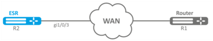
Solution:
Switch gigabitethernet 1/0/3 interface on which ToPGATE-SFP is set into E1 operation mode:
esr# configure
esr(config)# interface gigabitethernet 1/0/3
esr(config-if-gi)# description "*** ToPGATE ***"
esr(config-if-gi)# switchport mode e1
esr(config-if-gi)# switchport e1 timeslots 1-8
esr(config-if-gi)# switchport e1 clock source line
esr(config-if-gi)# switchport e1 slot 3
esr(config-if-gi)# exitEnable interface e1 1/3/1:
esr(config)# interface e1 1/3/1
esr(config-e1)# security-zone trusted
esr(config-e1)# ip address 10.77.0.1/24
esr(config-e1)# exitThe configuration changes come into effect after applying the following commands:
esr# commit
Configuration has been successfully committed
esr# confirm
Configuration has been successfully confirmedMLPPP Configuration
Multilink PPP (MLPPP) is an aggregated channel that encompasses methods of traffic transition via multiple physical channels while having a single logical connection. This option allows to enhance bandwidth and enables load balancing.

Configuration algorithm
Step | Description | Command | Keys |
|---|---|---|---|
1 | Configure aggregation group. | esr(config)# interface multilink <IF> | <IF> – interface name. |
2 | Specify the description of configured aggregation group (optionally). | esr(config-multilink)# description <DESCRIPTION> | <DESCRIPTION> – aggregation group description, set by the string of up to 255 characters. |
3 | Specify the time interval during which the statistics on the aggregation group load is averaged (optionally). | esr(config-multilink)# load-average <TIME> | <TIME> – interval in seconds, takes values of [5..150]. Default value: 5. |
4 | Specify MTU (Maximum Transmission Unit) size for the aggregation group (optionally). MTU above 1500 will be active only when using the "system jumbo-frames” command. | esr(config-multilink)# mtu <MTU> | <MTU> – MTU value, takes values in the range of [1280..1500]. Default value: 1500. |
5 | Enable CHAP authentication. | esr(config-multilink)# ppp authentication chap | |
6 | Enable authentication override (optionally). | esr(config-multilink)# ppp chap refuse | |
7 | Specify the router name that is sent to a remote party for CHAP authentication. | esr(config-multilink)# ppp chap hostname <NAME> | <NAME> – router name, set by the string of up to 31 characters |
8 | Specify the password that is sent with the router name to a remote party for CHAP authentication. | esr(config-multilink)# ppp chap password ascii-text | <CLEAR-TEXT> – unencrypted password, set by the string of [8..64] characters, may include [0-9a-fA-F] characters. <ENCRYPTED-TEXT> – unencrypted password, set by the string of [16..128] characters. |
9 | Allow any non-null IP address to be accepted as a local IP address from the neighbour (optionally). | esr(config-multilink)# ppp ipcp accept-address | |
10 | Set IP address that is sent to a remote party for the further allocation. | esr(config-multilink)# ppp iccp remote-address <ADDR> | <ADDR> – IP address of a remote gateway. |
11 | Specify a user for remote party authentication and switch to the specified user configuration mode. | esr(config-multilink)# chap username <NAME> | <NAME> – user name, set by the string of up to 31 characters. |
12 | Set encrypted or unencrypted password for a specific user to authenticate the remote party. | esr(config-ppp-user)# password ascii-text | <CLEAR-TEXT> – unencrypted password, set by the string of [8..64] characters, may include [0-9a-fA-F] characters. <ENCRYPTED-TEXT> – unencrypted password, set by the string of [16..128] characters. |
13 | Set the amount of attempts to send Configure-Request packets before the remote peer is found to be unable to respond (optional). | esr(config-multilink)# ppp max-configure <VALUE> | <VALUE> – time in seconds, takes values of [1..255]. Default value: 10. |
14 | Set the amount of attempts to send Configure-NAK packets before all options are confirmed (optionally). | esr(config-multilink)# ppp max-failure <VALUE> | <VALUE> – time in seconds, takes values of [1..255]. |
15 | Set the amount of attempts to send Terminate-Request packets before the session is aborted (optionally). | esr(config-multilink)# ppp max-terminate <VALUE> | <VALUE> – time in seconds, takes values of [1..255]. Default value: 2. |
16 | Set MRU (Maximum Receive Unit) size for the interface. | esr(config-multilink)# ppp mru <MRU> | <MRU> – MRU value, takes values in the range of [128..1485]. Default value: 1500. |
17 | Specify the time interval in seconds after which the router sends a keepalive message (optionally). | esr(config-multilink)# ppp timeout keepalive <TIME> | <TIME> – time in seconds, takes values of [1..32767]. Default value: 10. |
18 | Specify the time interval in seconds after which the router sends a keepalive message (optionally). | esr(config-multilink)# ppp timeout retry <TIME> | <TIME> – time in seconds, takes values of [1..255]. Default value: 3. |
19 | Specify the maximum packet size for MLPP interface. | esr(config-multilink)# mrru <MRRU> | <MRRU> – maximum size of a received packet for MLPP interface, takes value in the range of [1500..10000]. |
20 | Bind e1 port to the physical interface. | esr(config-if-gi)# switchport e1 <SLOT> | <SLOT> – slot identifier, takes values in the range of [0..3]. |
21 | Put the physical port into SFPe1 module operation mode. | esr(config-if-gi)# switchport mode e1 | |
22 | Enable MLPPP mode on E1 interface. | esr(config-e1)# ppp multilink | |
23 | Include E1 interface in the aggregation group. | esr(config-e1)# ppp multilink-group <GROUP-ID> | <GROUP-ID> – group identifier, takes values in the range of [1..4]. |
Configuration example
Objective:
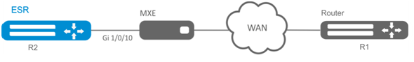
Configure MLPPP connection to the opposite side with IP address 10.77.0.1/24 via MXE device.
Solution:
Switch gigabitethernet 1/0/10 interface into E1 operation mode:
esr# configure
esr(config)# interface gigabitethernet 1/0/1
esr(config-if-gi)# switchport mode e1
esr(config-if-gi)# switchport e1 slot 0
esr(config-if-gi)# exit
esr(config)# interface gigabitethernet 1/0/2
esr(config-if-gi)# switchport mode e1
esr(config-if-gi)# switchport e1 slot 1
esr(config-if-gi)# exitConfigure MLPPP 3:
esr(config)# interface multilink 3
esr(config-multilink)# ip address 10.77.0.2/24
esr(config-multilink)# security-zone trusted
esr(config-multilink)# exit
esr(config)# exitEnable interface e1 1/0/1, interface e1 1/0/2 into MLPPP 3 aggregation group:
esr(config)# interface e1 1/0/1
esr(config-e1)# ppp multilink
esr(config-e1)# ppp multilink-group 3
esr(config-e1)# exit
esr(config)# interface e1 1/0/2
esr(config-е1)# ppp multilink
esr(config-е1)# ppp multilink-group 3
esr(config-е1)# exitBridge configuration
Bridge is a method of connection for two Ethernet segments on data-link level without any higher level protocols, such as IP. Packet transmission is based on Ethernet addresses, not on IP addresses. Given that the transmission is performed on data-link level (Level 2 of the OSI model), higher level protocol traffic passes through the bridge transparently.
Configuration algorithm
Step | Description | Command | Keys |
|---|---|---|---|
1 | Add a network bridge to the system and switch to its configuration mode. | esr(config)# bridge <BRIDGE-ID> | <BRIDGE-ID> – bridge identification number, takes values in the range of:
|
2 | Enable network bridge. | esr(config-bridge)# enable | |
3 | Specify VRF instance, in which the given modem will operate (optionally). | esr(config-bridge)# ip vrf forwarding <VRF> | <VRF> – VRF name, set by the string of up to 31 characters. |
4 | Specify the configured network bridge description (optionally). | esr(config-bridge)# description <DESCRIPTION> | <DESCRIPTION> – network bridge description, set by the string of up to 255 characters. |
5 | Connect sub interface, qinq interface, L2GRE tunnel or L2TPv3 tunnel with the network bridge. Connected interfaces/tunnels and network bridges automatically become participants of the shared L2 domain (optionally). | esr(config-if-gi)# bridge-group <BRIDGE-ID> esr(config-if-l2tpv3)# bridge-group <BRIDGE-ID> | <BRIDGE-ID> – bridge identification number, takes values in the range of:
|
6 | Connect the current network bridge with VLAN. All interfaces and L2 tunnels that are members of the assigned VLAN are automatically included in the network bridge and become members of the shared L2 domain (optionally) | esr(config-bridge)# vlan <VID> | <VID> – VLAN identifier, set in the range of [1..4094]. |
7 | Specify the size of MTU packets that can be passed by the bridge (optionally; possible if only VLAN is included in the bridge). | esr(config-bridge)# mtu <MTU> | <MTU> – MTU value, takes values in the range of:
Default value: 1500 |
8 | Specify the IPv4/IPv6 address and subnet mask for the interface to be configured or enable IP address obtain dynamically. | esr(config-bridge)# ip address <ADDR/LEN> | <ADDR/LEN> – IP address and subnet mask length, defined as AAA.BBB.CCC.DDD/EE where each part AAA-DDD takes values of [0..255] and EE takes values of [1..32]. For advanced IPv4 addressing features see section IP addressing configuration. |
esr(config-bridge)# ipv6 address <IPV6-ADDR/LEN> | <IPV6-ADDR/LEN> – IP address and prefix of a subnet, defined as X:X:X:X::X/EE where each X part takes values in hexadecimal format [0..FFFF] and EE takes values of [1..128]. For advanced IPv6 addressing features see section IPv6 addressing configuration. You can specify several IPv4/IPv6 addresses separated by commas. Up to 8 IPv4/IPv6 addresses can be assigned to the interface. | ||
esr(config-bridge)# ip address dhcp | For advanced DHCP client operation features, see section DHCP Client management. | ||
9 | Disable the Firewall features on the interface or enable the interface in the security zone (see Firewall configuration). | esr(config-bridge)# ip firewall disable | |
esr(config-bridge)# security-zone <NAME> | <NAME> – security zone name, set by the string of up to 31 characters. | ||
9 | Enable recording of the current interface usage statistics (optional). | esr(config-bridge)# history statistics | |
8 | Specify the time interval during which the statistics on the bridge load is averaged (optionally). | esr(config-bridge)# load-average <TIME> | <TIME> – interval in seconds, takes values of [5..150]. Default value: 5 |
9 | Specify the network bridge MAC address different from a system one (optionally). | esr(config-bridge)# mac-address <ADDR> | <ADDR> – network bridge MAC address, defined as XX:XX:XX:XX:XX:XX where each part takes the values of [00..FF]. |
10 | Enable interface isolation mode on the bridge. | esr(config-bridge)# protected-ports [ exclude vlan ] | exclude vlan – when specifying the given key, VLAN (connected with bridge) is excluded from the isolated interfaces list. |
11 | Prohibit unknown-unicast traffic switching (when a destination MAC address is not included in the switching table) in the given bridge. (Optionally; relevant only for ESR-1000/1200/1500/1511/1700 | esr(config-bridge)# unknown-unicast-forwarding disable | |
12 | Set the lifetime of IPv4/IPv6 entries in the ARP table studied on the given bridge (optionally). | esr(config-bridge)# ip arp reachable-time <TIME> or esr(config-bridge)# ipv6 nd reachable-time <TIME> | <TIME> – lifetime of dynamic MAC addresses, in milliseconds. Allowed values are from 5000 to 100000000 milliseconds. Real time of the entry update varies from [0,5;1,5]*<TIME>. |
It is also possible to configure the bridge interface:
| |||
Example of bridge configuration for VLAN and L2TPv3 tunnel
Objective:
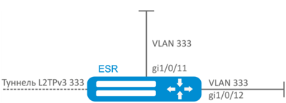
Combine router interfaces related to LAN and L2TPv3 tunnel passing through the public network into a single L2 domain. For combining, use VLAN 333.
Solution:
Create VLAN 333:
esr(config)# vlan 333
esr(config-vlan)# exitCreate 'trusted' security zone:
esr(config)# security-zone trusted
esr(config-zone)# exitAdd gi1/0/11, gi1/0/12 interfaces to VLAN 333:
esr(config)# interface gigabitethernet 1/0/11-12
esr(config-if)# mode switchport
esr(config-if)# switchport general allowed vlan add 333 taggedCreate bridge 333, map VLAN 333 to it and specify membership in 'trusted' zone:
esr(config)# bridge 333
esr(config-bridge)# vlan 333
esr(config-bridge)# security-zone trusted
esr(config-bridge)# enable Specify the affilation of L2TPv3 tunnel to bridge mapped to LAN (for L2TPv3 tunnel configuration, see Section L2TPv3 tunnel configuration). In general, bridge and tunnel identifiers should not match the VID, unlike this example.
esr(config)# tunnel l2tpv3 333
esr(config-l2tpv3)# bridge-group 333Example of bridge configuration for VLAN
Objective:
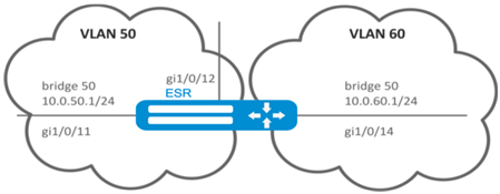
Configure routing between VLAN 50 (10.0.50.0/24) and VLAN 60 (10.0.60.0/24). VLAN 50 should belong to 'LAN1', VLAN 60 – to 'LAN2', enable free traffic transmission between zones.
Solution:
Create VLAN 50, 60:
esr(config)# vlan 50,60
esr(config-vlan)# exitCreate 'LAN1' and 'LAN2’ security zones:
esr(config)# security-zone LAN1
esr(config-zone)# exit
esr(config)# security-zone LAN2
esr(config-zone)# exitMap VLAN 50 to gi1/0/11, gi1/0/12 interfaces:
esr(config)# interface gigabitethernet 1/0/11-12
esr(config-if-gi)# switchport general allowed vlan add 50 taggedMap VLAN 60 to gi1/0/14 interface:
esr(config)# interface gigabitethernet 1/0/14
esr(config-if-gi)# switchport general allowed vlan add 60 taggedCreate bridge 50, map VLAN 50, define IP address 10.0.50.1/24 and membership in 'LAN1' zone:
esr(config)# bridge 50
esr(config-bridge)# vlan 50
esr(config-bridge)# ip address 10.0.50.1/24
esr(config-bridge)# security-zone LAN1
esr(config-bridge)# enable Create bridge 60, map VLAN 60, define IP address 10.0.60.1/24 and membership in 'LAN2' zone:
esr(config)# bridge 60
esr(config-bridge)# vlan 60
esr(config-bridge)# ip address 10.0.60.1/24
esr(config-bridge)# security-zone LAN2
esr(config-bridge)# enable Create firewall rules that enable free traffic transmission between zones:
esr(config)# security zone-pair LAN1 LAN2
esr(config-zone-pair)# rule 1
esr(config-zone-pair-rule)# action permit
esr(config-zone-pair-rule)# enable
esr(config-zone-pair-rule)# exit
esr(config-zone-pair)# exit
esr(config)# security zone-pair LAN2 LAN1
esr(config-zone-pair)# rule 1
esr(config-zone-pair-rule)# action permit
esr(config-zone-pair-rule)# enable
esr(config-zone-pair-rule)# exit
esr(config-zone-pair)# exit
esr(config)# exitTo view an interface membership in a bridge, use the following command:
esr# show interfaces bridgeConfiguration example of the second VLAN tag adding/removing
Objective:
The gigabitethernet 1/0/1 interface receives Ethernet frames with various VLAN tags. It is necessary to redirect them to the gigabitethernet 1/0/2 interface, adding the second VLAN-ID 828. When Ethernet frames with VLAN-ID 828 come on the gigabitethernet 1/0/2, this tag must be removed and sent to the gigabitethernet 1/0/1 interface.
Solution:
Create the bridge without VLAN and IP address on the route.
esr(config)# bridge 1
esr(config-bridge)# enable
esr(config-bridge)# exit Include the gigabitethernet 1/0/1 interface in bridge 1.
esr(config)# interface gigabitethernet 1/0/1
esr(config-if-gi)# bridge-group 1
esr(config-if-gi)# exit Include the gigabitethernet 1/0/2.828 sub interface in bridge 1.
esr(config)# interface gigabitethernet 1/0/2.828
esr(config-subif)# bridge-group 1
esr(config-subif)# exit When adding the second VLAN tag to an Ethernet frame, its size is increased by 4 bytes. MTU must be increased by 4 bytes or more on the gigabitethernet 1/0/2 router interface and on all equipment transmitting Q-in-Q frames.
Dual-Homing configuration
In the current firmware version, this functionality is supported only by ESR-1000 router.
Dual-Homing is a technology based on redundant links that creates a secure connection in order to prevent failures of the key network resources.
Configuration algorithm
Step | Description | Command | Keys |
|---|---|---|---|
1 | Specify a redundant interface to which the switching will occur when the connection is lost on a primary one. | esr(config-if-gi)# backup interface<IF> vlan <VID> | <IF> – interface to which the switching will occur <VID> – VLAN ID, set in the range of [2..4094]. You can also specify it by the range with “-” or by comma-separated list.. |
2 | Specify the number of packets copies with the same MAC address that will be sent to an active interface when switching (optionally). | esr(config)# backup-interface mac-duplicate <COUNT> | <COUNT> – amount of packets copies, takes values of [1..4]. |
3 | Specify the number of packets per second that will be sent to an active interface when switching (optionally). | esr(config)# backup-interfacemac-per-second<COUNT> | <COUNT> – amount of MAC addresses per second, takes value of [50..400]. |
4 | Specify that it is necessary to carry out the switching to the primary interface when restoring the communication (optionally). | esr(config)# backup-interface preemption |
Configuration example
Objective:
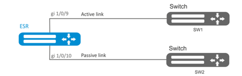
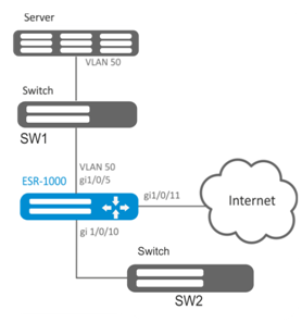
Establish redundancy of the ESR router L2 connections for VLAN 50-55 using SW1 and SW2 devices.
Solution:
First, do the following:
Create VLAN 50, -55:
esr(config)# vlan 50-55You should disable STP for gigabitethernet 1/0/9 and gigabitethernet 1/0/10 interfaces, i.e. these protocols cannot operate simultaneously:
esr(config)# interface gigabitethernet 1/0/9-10
esr(config-if-gi)# spanning-tree disableAdd gigabitethernet 1/0/9 and gigabitethernet 1/0/10 interfaces into VLAN 50-55 in 'general' mode.
esr(config-if-gi)# switchport general allowed vlan add 50-55
esr(config-if-gi)# exitMain configuration step:
Make gigabitethernet 1/0/10 redundant for gigabitethernet 1/0/9:
esr(config)# interface gigabitethernet 1/0/9
esr(config-if-gi)# backup interface gigabitethernet 1/0/10 vlan 50-55 To view information on redundant interfaces, use the following command:
esr# show interfaces backup Mirroring configuration (SPAN/RSPAN)
In the current firmware version the RSPAN functionality is supported only by ESR-1000/1200/1500/1511/1700 routers
Traffic mirroring is a feature of the router that allows for redirection of traffic from a specific port of the router to another port of the same router (local mirroring) or to a remote device (remote mirroring).
Configuration algorithm
Step | Description | Command | Keys |
|---|---|---|---|
1 | Define VLAN over which the mirrored traffic will be transmitted (in case of using remote mirroring). | esr(config)# port monitor remote vlan <VID> <DIRECTION> | <VID> – VLAN ID, set in the range of [2..4094]; <DIRECTION> – traffic direction:
|
2 | Enable the remote mirroring mode (in case of using remote mirroring). | esr(config)# port monitor remote | |
3 | Define the mode of the port transmitting mirrored traffic (optional). | esr(config)# port monitor mode <MODE> | <MODE> – mode:
|
4 | Enable mirroring in the interface configuration mode. | esr(config-if-gi)# port monitor interface <IF> [ <DIRECTION> ] | <IF> – interface from which the frames will be mirrored; <DIRECTION> – traffic direction:
|
Configuration example
Objective:
Establish remote mirroring of traffic through VLAN 50 from gi1/0/11 interface to be sent to server for processing purposes.
Solution:
First, do the following:
- Create VLAN 50:
- On gi 1/0/5 interface, add VLAN 50 in 'general' mode.
Main configuration step:
Specify VLAN that will be used for transmission of mirrored traffic:
еsr1000(config)# port monitor remote vlan 50 For gi 1/0/5 interface, specify a port for mirroring:
еsr1000(config)# interface gigabitethernet 1/0/5
еsr1000(config-if-gi)# port monitor interface gigabitethernet 1/0/11 For gi 1/0/5 interface, specify the remote mirroring mode:
еsr1000(config-if-gi)# port monitor remoteLACP configuration
LACP is a link aggregation protocol that allows multiple physical links to be combined into a single logical link. This process allows to increase the communication link bandwidth and robustness.
Configuration algorithm
Step | Description | Command | Keys |
|---|---|---|---|
1 | Set the system priority for LACP. | esr(config)# lacp system-priority <PRIORITY> | <PRIORITY> – priority, set in the range of [1..65535]. Default value: 1. |
2 | Set the load balancing mechanism for channel aggregation groups. | esr(config)# port-channel load-balance { src-dst-mac-ip | |
|
3 | Set LACP administration timeout. | esr(config)# lacp timeout {short | long } |
Default value: long. |
4 | Create and switch to the aggregated interface configuration mode. | esr(config)# interface port-channel <ID> | <ID> – sequence number of a channel aggregation group, takes values of [1..12]. |
5 | Configure the required parameters of aggregated channel. | ||
6 | Switch to the physical interface configuration mode. | esr(config)# interface <IF-TYPE><IF-NUM> | <IF-TYPE> interface type (gigabitethernet or tengigabitethernet). <IF-NUM> – F/S/P – F frame (1), S – slot (0), P – port. |
7 | Include a physical interface in the channel aggregation group specifying the mode of the channel aggregation group formation. | esr(config-if-gi)# channel-group <ID> mode <MODE> | <ID> – sequence number of a channel aggregation group, takes values of [1..12]. <MODE> – mode of the channel aggregation group formation:
|
8 | Set the Ethernet interface LACP priority. | esr(config-if-gi)# lacp port-priority <PRIORITY> | <PRIORITY> – priority, set in the range of [1..65535]. Default value: 1 |
9 | Set the time interval during which statistics on the sub-interface load is collected. (optionally). | esr(config-subif)# load-average <TIME> | <TIME> – interval in seconds, takes values of [5..150]. |
10 | Set the lifetime of IPv4/IPv6 entries in the ARP table studied on the given interface (optionally). | esr(config-subif)# ip arp reachable-time <TIME> or esr(config-subif)# ipv6 nd reachable-time <TIME> | <TIME> – lifetime of dynamic MAC addresses, in milliseconds. Allowed values are from 5000 to 100000000 milliseconds. Real time of the entry update varies from [0,5;1,5]*<TIME>. |
11 | Change MTU (MaximumTransmitionUnit) size. MTU above 1500 will be active only when using the «system jumbo-frames» command (optional). | esr(config-subif)# mtu <MTU> | <MTU> – MTU value in bytes. Default value: 1500. |
12 | Enable recording of the current interface usage statistics (optional). | esr(config-subif)# history statistics | |
13 | Override the MSS (Maximum segment size) field in incoming TCP packets (optional). | esr(config-subif)# ip tcp adjust-mss <MSS> esr(config-subif)# ipv6 tcp adjust-mss <MSS> | <MSS> – MSS value, takes values in the range of [500..1460]. Default value: 1460 |
It is also possible to configure the aggregated interface: · IPv4/IPv6 addressing (see sections IP addressing configuration, IPv6 addressing configuration and DHCP client management); · Firewall (see section Firewall configuration); · QoS in basic or advanced mode (see section QoS management. Firmware version 1.13.0); · proxy (see section HTTP/HTTPS traffic proxying); · traffic monitoring (see sections Netflow configuration and sFlow configuration); · routing protocols functionality (see section Routing management. Firmware version 1.13.0); · VRRF protocol (see section Redundancy management. Firmware version 1.13.0) · BRAS functionality (see section BRAS (Broadband Remote Access Server) management. Firmware version 1.13.0); · IDS/IPS functionality (see section IPS/IDS configuration). | |||
Configuration example
Objective:
Configure aggregated link between ESR router and the switch.

Solution:
First, do the following settings:
For gi1/0/1, gi1/0/2 interfaces disable security zone with 'no security-zone' command.
Main configuration step:
Create port-channel 2 interface:
esr(config)# interface port-channel 2Add gi1/0/1, gi1/0/2 physical interfaces into the created link aggregation group:
esr(config)# interface gigabitethernet 1/0/1-2
esr(config-if-gi)# channel-group 2 mode auto Further port-channel configuration is performed by analogy to the common physical interface.
AUX configuration
For ESR-21.
AUX configuration is used to specify parameters for interacting with external devices connected via serial interfaces to the ESR.
Configuration algorithm
Step | Description | Command | Keys |
|---|---|---|---|
1 | Switch to the serial interface configuration mode. | esr(config)# line aux <NUM> | <NUM> – a number of a serial interface from the range [1..3]. |
2 | Set the necessary serial interface parameters to communicate with the connected device (optional). These parameters are usually specified in the operation manual of the device to be connected. By default, the standard values will be used. | esr(config-line-aux) databits <BITS> esr(config-line-aux) flowcontrol <FMODE> esr(config-line-aux) parity <PMODE> esr(config-line-aux) speed <SPEED> esr(config-line-aux) stopbits <STOP-BITS> | <BITS> – a number of data bits sent [7..8]. Default is "8", <FMODE> – data flow control mode. Takes the following values:
Default is "disabled", <PMODE> – parity bit setting mode. Takes the following values: |
Default is "none", <SPEED> – a speed of a serial interface in bps. Takes the following values:
Default is "115200", <STOP-BITS> – the number of stop bits transmitted[1..2]; Default is "1". | |||
3 | Specify serial interface description (optional). | esr(config-line-aux)# description <DESCRIPTION> | <DESCRIPTION> – interface description, set by the string of up to 255 characters. |
4 | When using the device to be connected as a modem, set the serial interface to modem mode (optional). Note: cannot be used in conjunction with the «transport telnet port» command. | esr(config-line-aux)# modem inout | |
5 | When using the ESR as a terminal server to control a connected device on the serial interface, set the TCP port number to be used as the TCP port number to connect to the ESR via telnet (optional). Note: cannot be used in conjunction with the «modem inout» command. | esr(config-line-aux)# transport telnet port <PORT> | <PORT> – TCP port number for console server mode. Takes values in the range of [1..65535]. |
Configuration examples
Objective 1:
Configure IP communication between two ESRs on the serial port, using modems in Leased line mode (automatic modem mode), connected to each other by a telephone cable
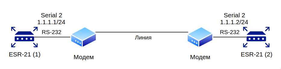
Modems should be previously entered into automatic connection setting mode.
Modem compatibility verified
Modem Zyxel U-336E Plus.
Solution:
Configure the first ESR-21
Configure negotiation parameters:
esr-21-1(config)# line aux 2
esr-21-1(config-line-aux)# flowcontrol hardware
esr-21-1(config-line-aux)# exit
esr-21-1(config)# Configure the required RS-232 interfaces:
esr-21-1(config)# interface serial 1/0/2
esr-21-1(config-serial)# ip address 1.1.1.1/24
esr-21-1(config-serial)# exit
esr-21-1(config)# Configure firewall for security zones:
esr-21-1(config)# security zone xx
esr-21-1(config-zone)# exit
esr-21-1(config)# security zone-pair xx self
esr-21-1(config-zone-pair)#   rule 1
esr-21-1(config-zone-pair-rule)# action permit
esr-21-1(config-zone-pair-rule)# enable
esr-21-1(config-zone-pair-rule)# exit
esr-21-1(config-zone-pair)# exit
esr-21-1(config)# Specify that the interfaces belong to the security zone:
esr-21-1(config)# interface serial 1/0/2
esr-21-1(config-serial)# security-zone xx
esr-21-1(config-serial)# exit
esr-21-1(config)#Configure the second ESR-21
Configure negotiation parameters:
esr-21-2(config)# line aux 2
esr-21-2(config-line-aux)# flowcontrol hardware
esr-21-2(config-line-aux)# exit
esr-21-2(config)# Configure the required RS-232 interfaces:
esr-21-2(config)# interface serial 1/0/2
esr-21-2(config-serial)# ip address 1.1.1.2/24
esr-21-2(config-serial)# exit
esr-21-2(config)# Configure firewall for security zones:
esr-21-2(config)# security zone xx
esr-21-2(config-zone)# exit
esr-21-2(config)# security zone-pair xx self
esr-21-2(config-zone-pair)#   rule 1
esr-21-2(config-zone-pair-rule)# action permit
esr-21-2(config-zone-pair-rule)# enable
esr-21-2(config-zone-pair-rule)# exit
esr-21-2(config-zone-pair)# exit
esr-21-2(config)# Specify that the interfaces belong to the security zone:
esr-21-2(config)# interface serial 1/0/2
esr-21-2(config-serial)# security-zone xx
esr-21-2(config-serial)# exit
esr-21-2(config)#Objective 2:
Set up IP connectivity between two ESRs on a Serial port, using Dial-Up modems and the Public Switched Telephone Network (PSTN)
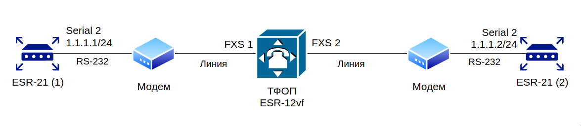
The ESR-12VF with the following configuration is used as a PSTN emulation:
dialplan pattern factory_test
  description "dialplan for factory test"
  pattern "S5, L5 (00[1-3]@{local} | [xABCD*#].S)"
  enable
exit
sip profile 1
  dialplan pattern "factory_test"
  enable
  proxy primary
    enable
    ip address proxy-server 192.0.2.5
    registration
    ip address registration-server 192.0.2.5
  exit
exit
interface voice-port 1
  sip user phone 001
  profile sip 1
exit
interface voice-port 2
  sip user phone 002
  profile sip 1
  caller-id mode fsk-bell
exitModem compatibility verified
- Modem ZyXEL OMNI 56K (MINI)
- Modem Acorp-M56SCD
Solution:
Configure the first ESR-21
Configure the parameters for negotiation with the modem:
esr-21-1(config)# line aux 2
esr-21-1(config-line-aux)# flowcontrol hardware
esr-21-1(config-line-aux)# modem inout
esr-21-1(config-line-aux)# exit
esr-21-1(config)# Configure the required RS-232 interfaces:
esr-21-1(config)# interface serial 1/0/2
esr-21-1(config-serial)# ip address 1.1.1.1/24
esr-21-1(config-serial)# exit
esr-21-1(config)# Configure firewall for security zones:
esr-21-1(config)# security zone xx
esr-21-1(config-zone)# exit
esr-21-1(config)# security zone-pair xx self
esr-21-1(config-zone-pair)#   rule 1
esr-21-1(config-zone-pair-rule)# action permit
esr-21-1(config-zone-pair-rule)# enable
esr-21-1(config-zone-pair-rule)# exit
esr-21-1(config-zone-pair)# exit
esr-21-1(config)# Specify that the interfaces belong to the security zone:
esr-21-1(config)# interface serial 1/0/2
esr-21-1(config-serial)# security-zone xx
esr-21-1(config-serial)# exit
esr-21-1(config)#Enable dialing by number:
esr-21-1(config)# interface serial 1/0/2
esr-21-1(config-serial)# dialer string 002
esr-21-1(config-serial)# dialer
esr-21-1(config-serial)# exit
esr-21-1(config)# Configure the second ESR-21
Configure negotiation parameters:
esr-21-2(config)# line aux 2
esr-21-2(config-line-aux)# flowcontrol hardware
esr-21-2(config-line-aux)# modem inout
esr-21-2(config-line-aux)# exit
esr-21-2(config)# Configure the required RS-232 interfaces:
esr-21-2(config)# interface serial 1/0/2
esr-21-2(config-serial)# ip address 1.1.1.2/24
esr-21-2(config-serial)# exit
esr-21-2(config)# Configure firewall for security zones:
esr-21-2(config)# security zone xx
esr-21-2(config-zone)# exit
esr-21-2(config)# security zone-pair xx self
esr-21-2(config-zone-pair)#   rule 1
esr-21-2(config-zone-pair-rule)# action permit
esr-21-2(config-zone-pair-rule)# enable
esr-21-2(config-zone-pair-rule)# exit
esr-21-2(config-zone-pair)# exit
esr-21-2(config)# Specify that the interfaces belong to the security zone:
esr-21-2(config)# interface serial 1/0/2
esr-21-2(config-serial)# security-zone xx
esr-21-2(config-serial)# exit
esr-21-2(config)#Objective 3:
Use additional modem settings for Objective 2
- for modem 1 enable the V.22bis protocol
- disable the speakers on both modems
Solution
Create a line with additional modem initialization parameters for the first ESR-21, where
- AT&N1" – enable V.22bis on modem mode
- ATM0L0 – disable modem speaker
esr-21-1(config)# chat-script dial_test "ABORT 'BUSY' ABORT 'NO CARRIER' ABORT ERROR '' AT OK AT&F OK AT&N14 OK ATM0L0 OK ATD\\T CONNECT ''"
esr-21-1(config)#Enable the use of the modem initialization string:
esr-21-1(config)# interface serial 1/0/2
esr-21-1(config-serial)# dialer string 001 modem-script dial_test
esr-21-1(config-serial)# exit
esr-21-1(config)#Create a line with additional modem initialization parameters for the second ESR-21:
esr-21-2(config)# chat-script answer_test "ABORT 'BUSY' ABORT 'NO CARRIER' '' AT OK AT&F OK ATM0L0 RING ATAr CONNECT ''"
esr-21-2(config)#Enable the use of the modem initialization string:
esr-21-2(config)# interface serial 1/0/2
esr-21-2(config-serial)# dialer string 000 modem-script answer_test
esr-21-2(config-serial)# exit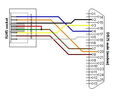
esr-21-2(config)#Adapter soldering schemes
RJ-45 <--> DB-25 pinout
RJ-45 <--> RJ-45 pinout (rolled over cable)