...
The range of ONT NTU equipment produced by ELTEX comprises of terminals with four UNI interfaces of 10/100/1000Base-T and supports for FXS 1 , Wi-Fi, USB, Z-Wave 2 , RF 3 :
- NTU-RG-5402G-W, NTU-RG-5421G-Wac, NTU-RG-5421GC-Wac, NTU-RG-5421G-WZ, NTU-RG-5440G-WZ, NTU-RG-5440G-Wac
...
NTU-RG series devices are designed to support various interfaces and features, see Table 1 .
| Якорь | ||||
|---|---|---|---|---|
|
...
- Network functions:
- bridge or router operation mode;
- PPPoE (auto, PAP, CHAP, MSCHAP authorization);
- IPoE (DHCP-client and static);
- static IP address and DHCP (DHCP client on WAN side, DHCP server on LAN side);
- Multicast traffic transmission via Wi-Fi;
- DNS (Domain Name System);
- DynDNS (Dynamic DNS);
- UPnP (Universal Plug and Play);
- IPsec (IP Security);
- NAT (Network Address Translation);
- Firewall;
- NTP (Network Time Protocol);
- QoS;
- IGMP snooping;
- IGMP proxy;
- Parental Control;
- Storage service;
- SMB, FTP, Print Server;
- VLAN in accordance with IEEE 802.1Q.
- Wi-Fi:
- support for IEEE 802.11a/b/g/n/ac standards;
- Simultaneous dual-band operation: 2.4 GHz and 5 GHz;
- support for EasyMesh.
- VoIP
- SIP
- Audio codecs: G.729 (A), G.711(A/U), G.723.1;
- ToS for RTP packets;
- ToS for RTP packets;
- Echo cancellation (G.164 and G.165 guidelines);
- Voice activity detection (VAD);
- Comfort noise generator (CNG);
- DTMF signal detection and generation
- DTMF transmission (INBAND, RFC2833, SIP INFO)
- Fax transmission: G.711, T.38;
- Caller ID display.
- Value added services (VAS):
- Call Hold;
- Call Transfer;
- Call Waiting;
- Forward unconditionally;
- Forward on «no answer»;
- Forward on «busy»;
- Caller ID Display for ETSI FSK;
- Anonymous calling;
- Warmline;
- Flexible dial plan;
- Voice mail notifications (MWI);
- Anonymous call blocking;
- Call Barring;
- DND (Do not disturb).
- Firmware updates via web interface, TR-069, OMCI.
- Remote monitoring, configuration, and setup:
- TR-069;
- Web interface;
- OMCI;
- CaTV 1 .
...
| Якорь | ||||
|---|---|---|---|---|
|
...
Figure 3 – NTU-RG-5421G-WZ and NTU-RG-5440G-WZ application diagram
Key Specifications
Table 2 shows main specifications of the terminals:
...
The rear panel layout of the device is depicted in Figures 4 , 5 , 6 , 7 .
| Якорь | ||||
|---|---|---|---|---|
|
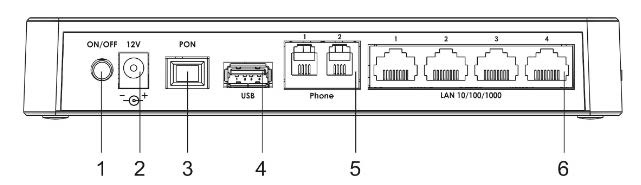
Figure 4 – NTU-RG-5402G-W-Wac rear panel layout
...
The connectors and controls located on the NTU-RG-5402G-W, NTU-RG-5421G-Wac and NTU-RG-5421G-WZ rear panel are listed in Table 3.
| Якорь | ||||
|---|---|---|---|---|
|
...
Connectors and controls located on the rear panel of the device are listed in Table 4.
| Scroll Pagebreak |
|---|
| Якорь | ||||
|---|---|---|---|---|
|
...
The connectors and controls located on the NTU-RG-5440G-Wac and NTU-RG-5440G-WZ rear panel are listed in Table 5.
| Якорь | ||||
|---|---|---|---|---|
|
№ | Rear panel element | Description |
|---|---|---|
| 1 | F | A functional key to reboot the device and reset it to factory settings |
2 | On/Off | Power button |
3 | 12V | Power adapter connector |
4 | LAN 10/100/1000 1..4 | 4 RJ-45 ports for connection to network devices |
5 | PON | SC port (socket) for PON with GPON interface |
6 | USB | Connector for external drives and other USB devices |
7 | Wi-Fi | Wi-Fi enabling/disabling button |
8 | WPS | A button to enable automatic secure Wi-Fi connection |
Figure below shows NTU-RG-5402G-W, NTU-RG-5421G-Wac and NTU-RG-5421G-WZ side panel layout.
...
Figure 8 – NTU-RG-5402G-W, NTU-RG-5421G-Wac and NTU-RG-5421G-WZ side panel layout
See Table 6 for detailed information about buttons located on the side panel of the device.
...
| Scroll Pagebreak |
|---|
Light Indication
Figure 9 shows NTU-RG-5402G-W, NTU-RG-5421G-Wac and NTU-RG-5421G-WZ top panel layout.
...
Current status of the device is represented by means of indicators paced on the top panel. Table 7 provides possible statuses of the LEDs.
...
The front panel of NTU-RG-5421GC-Wac is shown in Figure 10.
| Якорь | ||||
|---|---|---|---|---|
|
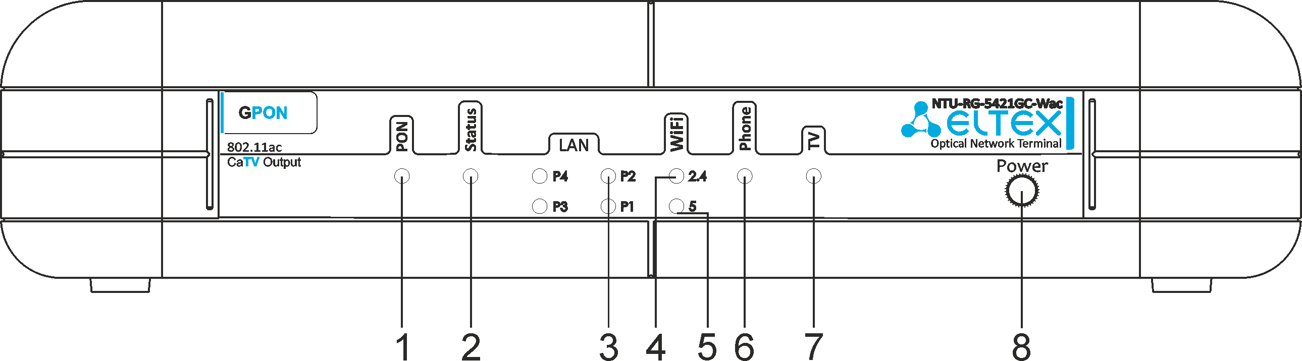
Figure 10 – NTU-RG-5421GC-Wac front panel layout
The LED indicators located on the front panel show the current state of the device. The list of indicator states is shown in Table 8.
| Scroll Pagebreak |
|---|
| Якорь | ||||
|---|---|---|---|---|
|
| № | Front panel element | LED status | Description |
|---|---|---|---|
| 1 | PON – optical interface activity indicator | off | device booting |
| green | connection between optical line terminal and the device has been established | ||
| flashes green | connection between optical line terminal and the device has been established (the device is not activated) | ||
| flashes green rapidly | device booting/connection to the Internet is being established | ||
| flashes red | no signal from optical line terminal | ||
| 2 | Status – status indicator | off | Internet interface is not configured |
| green | device is ready for operation, Internet connection is established | ||
| flashes green slowly | device firmware update is in progress | ||
| 3 | LAN P1..P4 – Ethernet port activity indicator | green | established 10/100 Mbps connection |
| orange | established 1000 Mbps connection | ||
| flashes | transferring data packets | ||
| 4 | WiFi 2.4 – Wi-Fi activity indicator for 2.4 GHz | green | Wi-Fi network is active |
| flashes | transmitting data via Wi-Fi | ||
| off | Wi-Fi network is inactive | ||
| 5 | WiFi 5 – Wi-Fi activity indicator for 5 GHz | green | Wi-Fi network is active |
| flashes | transmitting data via Wi-Fi | ||
| off | Wi-Fi network is inactive | ||
| 6 | Phone – FXS port activity indicator | off | SIP agent is not configured/not registered/off |
| on | SIP agent is successfully registered | ||
| flashes | off hook/phone call | ||
| 7 | TV – TV operation status indicator | green | 8dBm < CATV signal power < +2dBm |
| off | RF port is disabled | ||
| red | TV signal is not available | ||
| orange | signal level is not normal (more than +2 dBm) | ||
| 8 | Power – power and operation status indicator | off | device is disconnected from the power source or faulty |
| red | device startup is in progress | ||
| green | device startup completed, the current device configuration differs from the default one | ||
| orange | device startup is completed, the default configuration is set |
Figure 11 shows NTU-RG-5440G-Wac, NTU-RG-5440G-WZ top panel layout.
...
Current status of the device is represented by means of indicators paced on the top panel. Table 9 provides possible statuses of the LEDs.
...
Indication of LAN Interfaces
Table 10 lists operation modes shown by LAN ports LEDs located on the rear panel of the device.
...
A device with factory (initial) settings have the following logical blocks (see Figure 12 ):
- Br0;
- Voice (VoIP block);
- eth0…3;
- FXS0;
- wl0, wl0.1, wl0.2, wl0.3, wl1, wl1.1, wl1.2, wl1.3;
- IPInterface1.
...
The tab displays the current status of PON interface system.
Status → PON


PON Status
- Vendor Name – manufacturer name;
- Part Number – part number;
- Temperature – current temperature;
- Voltage – voltage;
- Tx Power – transmission power;
- Rx Power – reception power;
- Bias Current – bias current;
- Video Power – video signal power1.
PON Status
- ONU State – status of authorization on OLT (O1 -> O2 -> O3 -> O4 -> O5 );
- ONU ID – device identifier on OLT;
- LOID Status – status of authorization on OLT (Initial -> Standby -> Serial Number -> Ranging -> Operation).
...