...
| Оглавление | ||||||
|---|---|---|---|---|---|---|
|
Introduction
A GPON is a network of passive optical networks (PON) type. It is one of the most effective state-of-the-art solutions of the last mile issue that enables cable economy and provides information transfer downlink rate up to 2.5 Gbps and uplink rate up to 1.25 Gbps. Being used in access networks, GPON-based solutions allow end users to have access to new services based on IP protocol in addition to more common ones.
...
The range of ONT NTU equipment produced by ELTEX comprises of terminals with two UNI interfaces of 10/100/1000Base-T and supports for FXS, USB1, RF2 interfaces:
- NTU-52V, NTU-52VC
...
2For NTU-52VCЯкорь 2desc 2desc
Product Description
Purpose
NTU-52V/VC GPON ONT (Gigabit Ethernet Passive Optical Network) devices represent high-performance user terminals designed to establish a connection with upstream passive optical network equipment and to provide broadband access services to the end user. GPON connection is established through the PON interface, while Ethernet interfaces are used for connection of terminal equipment.
...
NTU-52VC device has an integrated RF output, to which a TV is connected to watch analog or digital cable television (if the service is provided by the carrier).
Models
NTU-52V/VC series devices are designed to support various interfaces and features, see Table 1.
| Якорь | ||||
|---|---|---|---|---|
|
| Model name | WAN | LAN | FXS | TV | USB |
|---|---|---|---|---|---|
| NTU-52V | 1xGPON | 1xFastEthernet, 1xGigabit Ethernet | 1 | - | 1 |
| NTU-52VC | 1xGPON | 1xFastEthernet, 1xGigabit Ethernet | 1 | 1 | - |
| Scroll Pagebreak |
|---|
Device Specification
Device is equipped with the following interfaces:
- Ports to connect network devices (FXS):
- 1xPON SC/APC port for connection to provider's network (WAN);
- Ethernet RJ-45 LAN ports for connection of network devices (LAN):
- 1 port of RJ-45 10/100Base-T (for details see Section 3. Design);
- 1 port of RJ-45 10/100/1000Base-T (for details see Section 3. Design);
- 1 USB 2.0 port for external USB or HDD storages2.
- 1 RF port for cable television (CaTV) connection1.
...
1Only for NTU-52VC Якорь 1 1
...
- Network functions:
- bridge or router operation mode;
- PPPoE (auto, PAP, CHAP, MSCHAP authorization);
- IPoE (DHCP-client and static);
- static IP address and DHCP (DHCP client on WAN side, DHCP server on LAN side);
- DNS (Domain Name System);
- DynDNS (Dynamic DNS);
- UPnP (Universal Plug and Play);
- IPsec (IP Security);
- NAT (Network Address Translation);
- Firewall;
- NTP (Network Time Protocol);
- QoS;
- IGMP snooping;
- IGMP proxy;
- Parental Control;
- Storage service;
- SMB, FTP, Print Server;
- VLAN in accordance with IEEE 802.1Q.
- VoIP
- SIP
- audio codecs: G.729 (A), G.711(A/U), G.723.1;
- echo cancellation (G.164 and G.165 guidelines);
- Voice activity detection (VAD);
- Comfort noise generator (CNG);
- DTMF signal detection and generation
- DTMF transmission (INBAND, RFC2833, SIP INFO)
- Fax transmission: G.711, T.38
- Caller ID display.
- Firmware updates via web interface, TR-069, OMCI.
- Remote monitoring, configuration and setup:
- TR-069;
- Web interface;
- OMCI.
- CaTV1.
...
1Only for NTU-52VC Якорь onemoredesc onemoredesc
...
Figure 1 – NTU-52V and NTU-52VC application diagram
| Scroll Pagebreak |
|---|
Key Specifications
Table 2 shows main specifications of the terminals:
...
| Model | NTU-52V | NTU-52VC | |
|---|---|---|---|
| Power supply | 12 VDC/220 VAC power adapter | 12 VDC/220 VAC power adapter | |
| RF port | - | 1 | |
| Max. power consumption | 10 W | ||
| Operating temperature | From +5 to +40°С | ||
| Relative humidity | 80% max. | ||
| Dimensions | 147×110×24 mm | 160×120×40 mm | |
| Weight | 0,3 kg | ||
| Якорь | ||||
|---|---|---|---|---|
|
Subscriber terminal is designed as desktop device in plastic housing.
The rear panel layout of the devices is depicted in Fig. 2, 3.
| Якорь | ||||
|---|---|---|---|---|
|
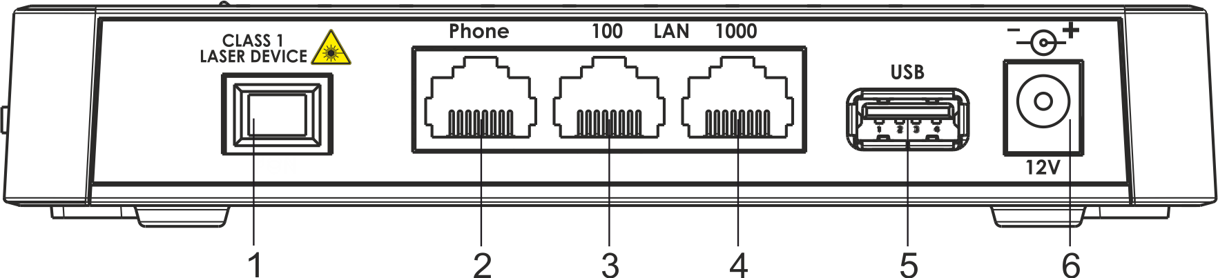
Figure 2 — NTU-52V rear panel layout
Connectors and controls located on the rear panel of 52V are listed in Table 3.
| Якорь | ||||
|---|---|---|---|---|
|
...
Connectors and controls located on the rear panel of 52VC are listed in Table 4.
| Scroll Pagebreak |
|---|
| Якорь | ||||
|---|---|---|---|---|
|
...
Figure 4 — NTU-52V side panel layout
See Table 5 for detailed information about buttons located on the side panel of the device.
...
# | Side panel element | Description |
|---|---|---|
1 | LED | LED on/off button |
2 | Reset/restore | A functional key that reboots the device and resets it to factory settings |
| Scroll Pagebreak |
|---|
Light Indication
The top panel layout of the NTU-52V is depicted in Fig. 5, the front panel layout is depicted in Fig. 6.
| Якорь | ||||
|---|---|---|---|---|
|

Figure 5 — NTU-52V top panel layout
...
The LED indicators located on the top and front panels show the current device status. Table 6 lists possible statuses of the LEDs.
| Scroll Pagebreak |
|---|
...
The front panel layout of the NTU-52VC is depicted in Figure 7.
| Якорь | ||||
|---|---|---|---|---|
|
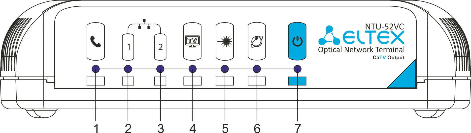
Figure 7 — NTU-52VC front panel layout
The LED indicators located on the front panel show the current state of the device. Table 7 provides possible statuses of the LEDs.
...
| # | Front panel element | LED Status | Description |
|---|---|---|---|
| 1 | | off | phone is off hook |
| flashes green | receiving a call | ||
| green | phone is on hook | ||
| 2-3 | | green | established 10/100 Mbps connection |
| flashes green rapidly | data transfer is in progress | ||
| green | established 10/100 Mbps connection | |
| orange | established 1000 Mbps connection | ||
| flashes green/orange rapidly | data transfer is in progress | ||
| 4 | | off | RF port is disabled |
| orange | CaTV signal power is in the range from -10 dBm..-8 dBm or +2 dBm..+3 dBm | ||
| green | -8dBm < CaTV signal power < +2dBm | ||
| 5 | | off | device is rebooting |
| flashes red | the device is not connected to OLT | ||
| flashes green | the device is in the registration process on OLT | ||
| green | the device is connected and registered on OLT | ||
| 6 | | off | there is no active connection to Internet |
| green | the device is ready, connection established | ||
| orange | the device is in connection process | ||
| 7 | | off | power is disconnected or device is fault |
| green | device startup completed, the current device configuration differs from default | ||
| orange | device startup is completed, the default configuration is set | ||
| red | device is booting | ||
| flashes slowly | the firmware update process is in progress |
Reboot and Reset to Factory Settings
To reboot the device, press the 'Reset' button located on its side panel. In order to reset the device to the factory settings, press the 'Reset' button and hold it for 7-10 seconds until the indicator glows red and all other LEDs go out. Factory settings for IP address are: LAN - 192.168.1.1, subnet mask – 255.255.255.0. Access can be provided from LAN 1 and LAN 2.
Delivery Package
The NTU-52V/VC standard delivery package includes:
- NTU-52V/VC optical network terminal;
- 220V/12V power adapter;
- User manual.
NTU-52V/VC architecture
| Якорь | ||||
|---|---|---|---|---|
|
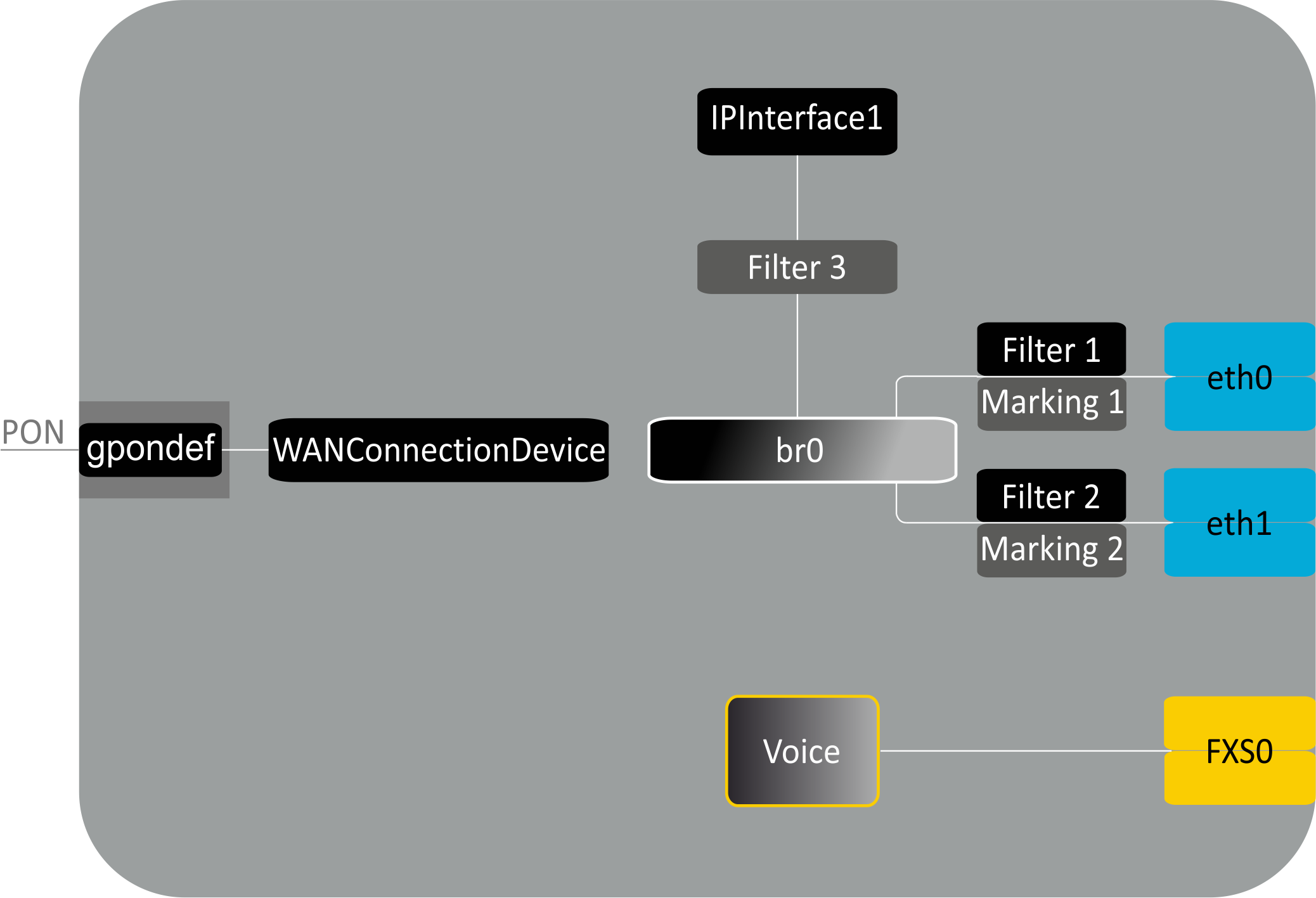
Figure 8 – Logical architecture of a device with factory settings
...
A device with factory (initial) settings have the following logical blocks (see Fig.8):
- Br0;
- Voice (VoIP block);
- eth0…1;
- FXS0;
- IPInterface1.
...
IPInterface1 block is a logical entity on which IP address providing the access in LAN and DHCP server distributing addresses to clients are located.
Device configuration via Web interface. Administrator Access
Getting Started
To configure the device, it is necessary to connect to it through Web browser:
...
- The navigation tree on the device settings menu.
- The main settings window for the selected section.
- User change button.
Scroll Pagebreak
The 'Status' menu. Device Information
The 'Device status' submenu. Device General Information
This section displays general information about the device, the main parameters of the LAN and WAN interfaces.
...
Click the 'Refresh' button to update the page.
The 'IPv6 Status' submenu. Information about IPv6 system
The tab displays the current status of IPv6 system.
...
Click the 'Refresh' button to update the page.
| Scroll Pagebreak |
|---|
The 'PON' submenu. Optical module status information
The tab displays the current status of PON interface system.
...
Click the 'Refresh' button to update the page.
| Scroll Pagebreak |
|---|
The 'LAN' menu LAN interface configuration
You can configure main parameters of LAN interfaces in this section.
...
- Interface name – interface name;
- IP Address – interface IP address;
- Subnet Mask – interface subnet mask;
- IPv6 Address Mode – access to the device via IPv6 address:
- Auto – when checked, the access to the device via IPv6 address will be granted automatically;
- Manual – when checked, you need to specify the IPv6 address manually :
- IPv6 Address – IPv6 address;
- IPv6 Prefix Length – length of the IPv6 address;
- IP Version – IP protocol version used (IPv4 or IPv4/IPv6);
- Firewall (Enabled/Disabled) – enable/disable firewall for LAN interface;
- IGMP Snooping (Enabled/Disabled) – enable/disable IGMP Snooping.
Scroll Pagebreak
The Services menu. Service configuration
The 'DHCP Setting' submenu. DHCP configuration
The menu allows DHCP server and DHCP repeater configuration.
...
To save the changes, click the 'Apply Changes' button. 'Port-Based Filter' and 'MAC-Based Assignment' buttons allow configuring port-based and MAC-based filtering, respectively.
The 'Dynamic DNS' submenu. Dynamic DNS Configuration
Dynamic DNS (domain name system) allows information to be updated on DNS server in real time and (optionally) automatically. It is applied for assignment of a constant domain name to a device (computer, router, e.g. NTU-52V/VC) having a dynamic IP address. The IP address can be assigned by IPCP in PPP connections or in DHCP.
...
'Dynamic DNS Table' table with the list of available DNS displayed in this section. To add a record, click the 'Add' button. To remove/modify a record, click the 'Remove'/'Modify' button for the selected record.
The 'Firewall' submenu. Firewall configuration
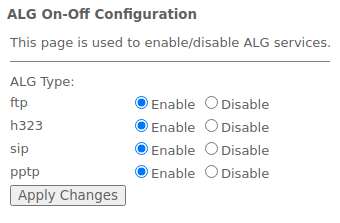
The 'ALG' submenu. Enable/disable ALG services
This section is used to enable/disable ALG services.
...
Services → Firewall → ALG
The 'IP/Port Filtering' submenu. Address Filtering Settings
This section is used to configure address filtering. The IP Filtering function filters router traffic by IP addresses and ports.Using these filters can be useful to protect or restrict the local network.
...
Added filters are displayed in the 'Current Filter Table' located below. The entries in this table are used to restrict certain types of data packets pass through the gateway. To delete a specific filter, select the position and click the 'Delete selected' button, to delete all filters click 'Delete All'.
The 'MAC Filtering' submenu. Filtering Settings for MAC Addresses
MAC filtering allows traffic to be forwarded or blocked depending on source and destination MAC addresses. To change the mode click the 'Apply Changes' button.
...
Added filters are displayed in the 'Current Filter Table' located below. The 'Rule' field displays the type of created rule ('Allow' - allowing or 'Deny' - forbidding). To remove selected items in the list, click 'Delete Selected'; click 'Delete All' to remove the whole list.
| Scroll Pagebreak |
|---|
The 'Port Forwarding' submenu. Port forwarding configuration
'Current Port Forwarding Table' with port forwarding information is displayed in this section. Entries in this table allow you to automatically redirect common network services to a specific machine behind the NAT firewall. These settings are only necessary if you wish to host some sort of server like a web server or mail server on the private local network behind your router's NAT firewall. To save the changes, click the 'Apply Changes' button.
...
After filling the fields click the 'Add' button to add the entry. To delete a selected position, click the 'Delete Selected' button; to delete the whole table, click the 'Delete All' button.
The 'URL Blocking' submenu. Internet access restriction configuration
URL filter performs complete analysis and provides access control to specific Internet resources. This section sets and displays a list of forbidden/allowed URLs to visit. Here you can add the forbidden/allowed FQDN (Fully Qualified Domain Name) with the 'Add' button, filtering by keywords is also possible. The added restrictions are displayed in the 'URL Blocking Table' and the 'Keyword Filtering Table'. To remove a specific URL or keyword from the table, click on it and then on the 'Delete Selected' button. To delete all restrictions click the 'Delete All' button.Scroll Pagebreak
...
To save the changes, click the 'Apply Changes' button.
The 'Domain Blocking' submenu. Domain blocking configuration
This section is used to set domain blocking.
...
To save the changes, click the 'Apply Changes' button. All blocked domains are listed in the 'Domain BlockingConfiguration' table, to remove a blocking for one domain, select it and click the 'Delete Selected' button, to remove all restrictions, click the 'Delete All' button.
The 'DMZ' submenu. Demilitarized Zone configuration
When an IP address is set in the 'DMZ host IP address field', all requests from external network, that do not satisfy the 'Port Forwarding' rules, will be redirected to a DMZ host (a trusted host with the specified address in the local network).Scroll Pagebreak
...
To save the changes, click the 'Apply Changes' button.
The 'UPnP' submenu. Automated Setup of Network Devices
In this section you can configure Universal Plug and Play (UPnP™) function. UPnP ensures compatibility with network equipment, software and peripheral devices.
...
To save the settings, click the 'Apply Changes' button.
The 'RIP' submenu. Dynamic routing configuration
This section is used to select the interfaces on your device is that use RIP, and the version of the protocol used. Enable the RIP if you are using this device as a RIP-enabled Device to communicate with others using the Routing Information Protocol.
...
Interfaces with the support for RIP are displayed in the 'RIP Config Table'. To delete all entries in the table click the 'Delete All' button; to delete one position from the list select it and click 'Delete Selected'.
The 'Samba' submenu. Configuration of Samba users
In this submenu you can configure Samba users.
...
- Share name – library name;
- Path – path to library;
- Read only – read only;
- Write list – list of accounts who can change files in the library;
- Comment – comment for the library.
The 'Advance' menu. Advanced settings
The 'ARP Table' menu. View ARP cache
This section shows a list of learned MAC addresses. The ARP efficiency depends a lot on ARP cache presented in every host. The cache contains Internet addresses and corresponding hardware addresses. Every record created in the cache is stored for 5 minutes.
...
To update the information, click the 'Refresh' button.Scroll Pagebreak
The 'Bridging' submenu. Bridging parameters configuration
In this section you can configure bridge parameters. Here you can configure aging time of addresses in MAC table as well as to enable/disable 802.1d Spanning Tree.
...
To update the information in the table, click the 'Refresh' button, to close the table, click 'Close'.Scroll Pagebreak
The 'Routing' submenu. Routing configuration
This submenu is used to configure static routing.
...
To update the information in the table, click the 'Refresh' button, to close the table, click 'Close'.Scroll Pagebreak
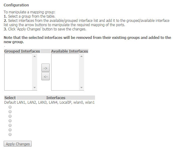
The 'Bridging grouping' submenu. Interface grouping
In this section you can group the interfaces. By default all interfaces are in the same group. To place an interface to a new group, you should:
...
Advance → Bridge grouping
Scroll Pagebreak
The 'Link mode' submenu. LAN ports configuration
In this submenu you can set the LAN ports operation mode. LAN1/2 – operation mode configuration; available modes: 10M Half Mode, 10M Full Mode, 100M Half Mode, 100M Full Mode and Auto Mode (auto-negotiation mode).
...
To save the changes, click the 'Apply Changes' button.
The 'IPv6' submenu. IPv6 configuration
In this section you can enable/disable IPv6 operation. For this you should check 'Enable/Disable'.
...
To save the changes, click the 'Apply Changes' button.
The 'RADVD' submenu. RADVD configuration
In this submenu you can configure RADVD (Router Advertisement Daemon).
...
To save the changes, click the 'Apply Changes' button.
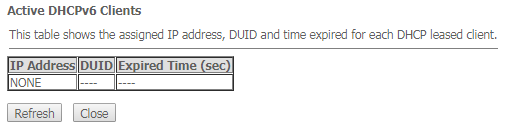
The 'DHCPv6 setting' submenu. DHCPv6 server configuration
This submenu is used to configure DHCPv6 server. By default, it operates in auto configuration mode (DHCPServer(Auto)) via prefix delegation.
...
Advance → IPv6 → DHCPv6 → Show Client
The 'MLD proxy' submenu. MLD proxy function configuration
In this section you can enable/disable MLD-proxy operation. For this you should check 'Enable/Disable'.
...
To save the changes, click the 'Apply Changes' button.Scroll Pagebreak
The 'MLD snooping' submenu. MLD snooping function configuration
In this section you can enable/disable MLD-snooping operation. For this you should check 'Enable/Disable'.
...
To save the changes, click the 'Apply Changes' button.
The 'IPv6 routing' routing. IPv6 routes configuration
This section configures static IPv6 routes.
...
To update the table click 'Refresh'; to close it click 'Close'
The 'IPv6 IP/ Port filtering' submenu. Packet filtering configuration
Use this page to configure the filtering of data packets transmitted through the gateway.
...
To add a filter fill the corresponding fields and click the 'Add' button. Added filters are displayed in the 'Current Filter Table'. To delete the whole table, click the 'Delete All' button; To delete one filter, select it and click the 'Delete Selected' button.
The 'Diagnostics' menu
The 'Ping' submenu. Checking the Availability of Network Devices
Use this menu to test the availability of network devices with Ping utility.
...
To test the availability of the connected device, enter its IP address into the 'Host Address' field and click the 'Go' button.
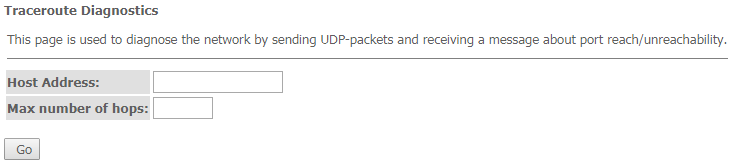
The 'Traceroute' submenu
This submenu is intended for network diagnostics by sending UDP packets and receiving a message about port availability/inaccessibility.
Diagnostics → Traceroute
| Scroll Pagebreak |
|---|
The 'Admin' menu
Device management section. In this menu, you can configure passwords, time, configurations, etc.
The 'Settings' submenu. Configuration restore and reset
Admin → Settings → Backup Settings
...
In this section you can reset the current settings to the factory default settings (Restore Default), click the 'Reset Settings to Default' button.
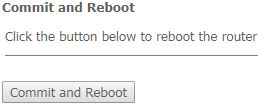
The 'Commit/Reboot' submenu. Saving changes and rebooting the device
Click the 'Commit and Reboot' button to reboot the device or to save changes in system memory. The rebooting process takes a few minutes to complete.
Admin → Commit/Reboot
Scroll Pagebreak
The 'Logout' submenu
In this section it is possible to log out by clicking on the 'Logout' button.
Admin → Logout

The 'Password' submenu. Access control configuration (setting passwords)
In this section you can change a password to access the device.
...
To confirm and save changes, click the 'Apply changes' button. Click the 'Reset' button to reset the value.
| Scroll Pagebreak |
|---|
The 'Firmware upgrade' submenu. Software Update
To update firmware, it is necessary to select firmware file by using the 'Select file' button and click 'Upgrade'. To reset the value, click the 'Reset' button.
...
| Подсказка |
|---|
Do not switch off or reboot the device during the update. The process may take several minutes. The device will be automatically rebooted when the update is completed. |
The 'Remote Access' submenu. Remote access rules configuration
In this section you can configure remote access rules via HTTP/Telnet/ICMP protocols.
...
To add a rule fill the corresponding fields and click the 'Add' button. Added rules are displayed in the 'RA Table'. To activate/deactivate the selected rule, click the 'Toggle selected' button. To delete one rule, select it with a flag in the Select column and click the 'Delete Selected' button.
The 'Time zone' submenu. System time configuration
In this section you can configure the device system time. Synchronization with accurate online time-servers is available.
...
To save the changes click the 'Apply Changes' button, update the information click 'Refresh'.
| Scroll Pagebreak |
|---|
The 'Statistics' menu. Traffic flow information for device ports
The 'Interface' submenu. Information about timers and errors
This section displays timers/errors for packets for each interface:
...
- Interface – interface;
- Rx pkt – packets received;
- RX err – errors on receive;
- Rx drop – rejected on receive;
- Tx pkt – packets sent;
- Tx err – transmission error;
- Tx drop – rejected on transmission.
Scroll Pagebreak
The 'PON' submenu
This section displays timers for the optical interface:
...
- Bytes Sent – transmitted bytes;
- Bytes Received – received bytes;
- Packets Sent – packets transmitted;
- Packets Received – packets received;
- Unicast Packet Sent – Unicast packets transmitted;
- Unicast Packet Received – Unicast packets received;
- Multicast Packets Sent – Multicast packets transmitted;
- Multicast Packets Received – Multicast packets received;
- Broadcast Packet Sent – Broadcast packets transmitted;
- Broadcast Packet Received – Broadcast packets received;
- FEC Errors – FEC errors
- Packets Dropped – packets rejected.
The list of changes
Document version | Suitable firmware version | Issue date | Revisions |
|---|---|---|---|
Version 1.2 | 1.3.2 | 11.2020 | Synchronization with Firmware version 1.3.2 |
Version 1.1 | 1.3.0 | 04.2020 | Second issue |
Version 1.0 | 1.2.1 | 01.2020 | First issue |
...