...
| Local control | web interface |
|---|---|
| Remote control | OMCI |
| Firmware version updating | OMCI, HTTP |
| Access restriction | by password |
...
| Power supply | 12 V, 2 A power adapter | ||
|---|---|---|---|
| Power consumption | up to 10 W | ||
| Operating temperature | from +5 to +40 °C | ||
| Relative humidity | up to 80 % | ||
| Dimensions (W × H × D) | 234 × 34 × 133 mm (NTX-1) 234 × 36 × 135 mm (NTX-1F) | ||
| Lifetime | at least 5 years |
| Якорь | ||||
|---|---|---|---|---|
|
...
Table 3. Description of connectors and controls of NTX-1 rear panel
| No. | Rear Panel Element | Description |
|---|---|---|
| 1 | F | Reset to default settings |
| 2 | ON/OFF | ON/OFF switch |
| 3 | 12V | Power adapter connector |
| 4 | 1G/10G | RJ-45 100/1000/2.5G/5G/10GBASE-T port for network devices connection |
| 5 | 1G | RJ-45 10/100/1000BASE-T port for network devices connection |
| 6 | PON | SC/APC connector (socket) XGS-PON optical interface GPON |
...
The subscriber terminal is enclosed in a plastic case with dimensions of 234 × 36 × 135 mm.
The rear panel of NTX-1F is shown in Figure 3 below.

Fig. 3. NTX-1F Rear Panel Layout
...
| Scroll Pagebreak |
|---|
| No. | Rear Panel Element | Description |
|---|---|---|
| 1 | F | Reset to default settings |
| 2 | ON/OFF | ON/OFF switch |
| 3 | 12V | Power adapter connector |
| 4 | 1G/10G | 10 GbE Ethernet port (SFP+) for network devices connection |
| 5 | 1G | RJ-45 10/100/1000BASE-T port for network devices connection |
| 6 | PON | SC/APC connector (socket) XGS-PON optical interface GPON |
NTX-1, NTX-1F Light Indication
The front panel of NTX-1, NTX-1F is shown in Figure 4 below.
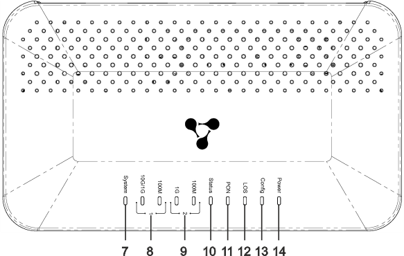
Fig. 4. NTX-1, NTX-1F Front Panel Layout
...
Table 5. Description of NTX-1, NTX-1F front panel indicators
| No. | Front Panel Element | Indicator State | Description |
|---|---|---|---|
7 | System | Off | The Linux system did not start |
| On | The Linux system started successfully | ||
| Flashing | Updating via OMCI | ||
| 8 | LAN 1 10G/1G indicator | Off | Cable is not connected |
| Yellow | 1/10 Gbps connection has been established | ||
| Flashing yellow | Data transfer is in progress | ||
| LAN 1 100M indicator | Off | Cable is not connected | |
| Green | 100 Mbps connection has been established | ||
| Flashing green | Data transfer is in progress | ||
9 | LAN 2 1G indicator | Off | Cable is not connected |
| Yellow | 1 Gbps connection has been established | ||
| Flashing green | Data transfer is in progress | ||
| LAN 2 100M indicator | Off | Cable is not connected | |
| Green | 100 Mbps connection has been established | ||
| Flashing green | Data transfer is in progress | ||
| 10 | Status | Off | An error occurred during OMCI configuration progress |
| Green | The OMCI configuration has completed successfully, the device is in operation | ||
| Flashing green | OMCI configuration obtaining is in progress | ||
11 | PON | Off | Optic cable is not connected/laser is disabled on OLT side |
| Green | The device is connected and registered on OLT | ||
| Flashing green | Registration on OLT is in progress | ||
| 12 | LOS | Off | Signal from OLT present |
| Red | Optic cable is not connected | ||
| Flashing red | Laser is disabled on OLT side | ||
| 13 | Config | Off | Standard configuration is set |
| Green | Not standard configuration is set | ||
14 | Power | Off | The device is unplugged or faulty |
| Green | Power on |
...
- Open a web browser (hypertext document viewer), for example, Firefox, Google Chrome.
- Enter the device IP address in the browser address bar.
| Подсказка |
|---|
Default IP address of the device is 192.168.1.1; subnet mask is 255.255.255.0. |
When the device is successfully detected, username and password request page will be shown in the browser window:
...