LTP-8X, LTP-4X optical line terminals
Application to the user manual
LTP-X quick configuration manual
Firmware version 3.38.2 (20.05.2020)
Notes and warnings
Notes contain important information, tips, or recommendations on device operation and setup.
Warnings are used to inform the user about harmful situations for the device and the user alike, which could cause malfunction or data loss.
Annotation
This manual specifies the following:
Safety rules and Installation procedure
- connection to the OLT LTP-X (hereinafter – the device) command line interface;
- OLT network parameters configuration;
- VLAN configuration to provide different services on switch;
- IGMP configuration on switch;
- creation and modification of ONT profiles: Cross-connect, Ports, Management;
- creation and modification of OLT profiles: pppoe-ia, dhcp-ra;
- addition of ONT subscriber devices.
The following scheme is given as an example.
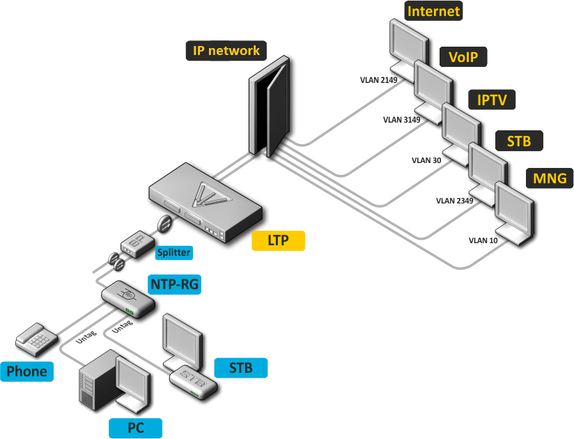
Figure 1 – Example of network configuration
Service type | VLAN used |
|---|---|
Internet | 2149 |
VoIP | 3149 |
IPTV (multicast) | 30 |
STB | 2349 |
MNG-ONT (acs) | 4094 |
MNG OLT | 4000 |
You will need the PC application supporting Telnet or SSH protocol operation or direct connection via the console port (e.g. HyperTerminal).
Safety rules and Installation procedure
Safety requirements
General requirements
Any operations with the terminal should comply to the Safety Rules for Operation of Customers' Electrical Installations.
Operations with the terminal should be carried out only by personnel authorised in accordance with the safety requirements.
- Before operating the device, all engineers should undergo special training.
- The terminal should be connected only to properly functioning supplementary equipment.
- The device could be permanently used provided the following requirements are met:
- ambient temperature from 5 to +40°C;
- relative humidity up to 80% at +25°C;
- Atmosphere pressure from 6,0х10*4 to 10,7х10*4 Pa (from 450 to 800 mm Hg).
- The terminal should be not be exposed to mechanical shock, vibration, smoke, dust, water, and chemicals.
- To avoid components overheating which may result in device malfunction, do not block air vents or place objects on the equipment.
Electrical Safety Requirements
- Prior to connecting the device to a power source, ensure that the equipment case is grounded with an earth bonding point. The earthing wire should be securely connected to the earth bonding point. The resistance between the earth bonding point and earthing busbar should be less than 0,1 Ω.
- PC and measurement instruments should be grounded prior to connection to the terminal. The potential difference between the equipment case and the cases of the instruments should be less than 1V.
- Prior to turning the device on, ensure that all cables are undamaged and securely connected.
- Make sure the device is off, when installing or removing the case.
- Replacement of power modules is carried out:
- for LTP-X, LTP-X rev.B only when the power is off;
- for LTP-X rev.C without turning off the power.
- You can install or remove SFP transceivers. This operation does not require the terminal to be turned off.
Terminal installation
Check the device for visible mechanical damage before installing and turning it on. In case of any damage, stop the installation, fill in a corresponding document and contact your supplier. If the terminal was exposed to low temperatures for a long time before installation, leave it for 2 hours at ambient temperature prior to operation. If the device was exposed to high humidity for a long time, leave it for at least 12 hours in normal conditions prior to turning it on.
Support brackets mounting
The delivery package includes support brackets for rack installation and mounting screws to fix the terminal case on the brackets. To install the support brackets:
- Step 1. Align four mounting holes in the support bracket with the corresponding holes in the side panel of the device.
- Step 2. Use a screwdriver to screw the support bracket to the case.
- Step 3. Repeat steps 1 and 2 for the second support bracket.
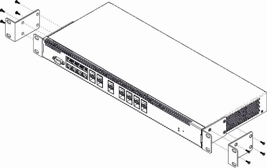
Figure 2 – Support brackets mounting
Terminal rack installation
To install the terminal to the rack:
- Step 1. Attach the terminal to the vertical guides of the rack.
- Step 2. Align mounting holes in the support bracket with the corresponding holes in the rack guides. Use the holes of the same level on both sides of the guides to ensure the device horizontal installation.
- Step 3. Use a screwdriver to screw the terminal to the rack.
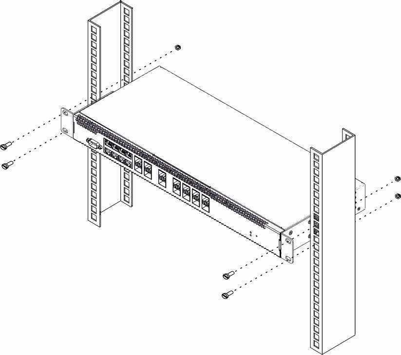
Figure 3 – Device rack installation
The terminal is horizontally ventilated. The side panels have air vents. Do not block the air vents to avoid components overheating and subsequent terminal malfunction.
To avoid overheating and provide necessary ventilation of the terminal, sufficient space should be provided above and below the terminal, not less than 10 cm.
Power module installation
Depending on power supply requirements, terminals can be supplemented with either an AC power module, 220 V, 50 Hz, or a DC power supply module, 48 V. The installation location for the power module for LTP-X, LTP-X rev.B is shown in Figure 4.
The installation locations for the power modules for LTP-X rev.C are shown in Figure 5.
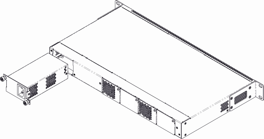
Figure 4 – Power module installation for LTP-X, LTP-X rev.B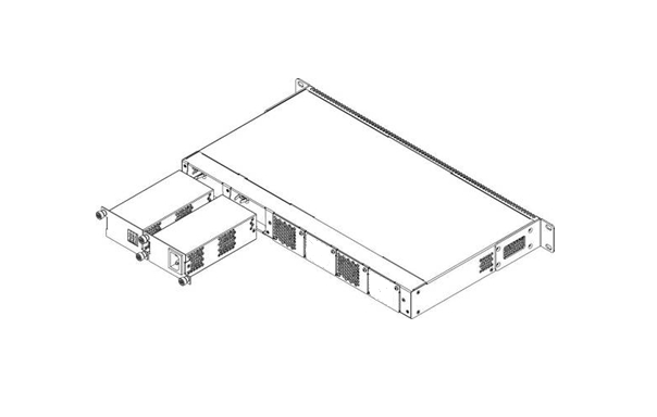
Figure 5 – Power module installation for LTP-X rev.C
To install a power module:
- Step 1. Install the power module into the socket shown in figure above;
- Step 2. Screw the power module to the case;
- Step 3. Turn the power on.
Connecting to power supply
- Step 1. Mount the device. In case of installation to a 19" form-factor rack, mount the support brackets from the delivery package to the rack.
- Step 2. Ground the case of the device. This should be done prior to connecting the device to the power supply. An insulated multiconductor wire should be used for earthing. The device grounding and the earthing wire section should comply with Electric Installation Code. The earth bonding point is located at the right bottom corner of the rear panel.
- Step 3. If you intend to connect a PC or another device to the switch console port, the device must be properly grounded as well.
- Step 4. Connect the power supply cable to the device.
- Step 5. Turn the device on and check the front panel LEDs to make sure the terminal is in normal operating conditions.
Connecting to the Command Line Interface (CLI)
Connecting via telnet/ssh
Connect the network data cable to one of the 'GE Port' or 'Combo GE' of LTP-X. The following factory settings are used for SSH/Telnet connection:
- Default IP: 192.168.1.2
- Default mask: 255.255.255.0
- Default GW: 0.0.0.0
- Login: admin
- Password: password
login: admin
Password: password
For security reasons, it is recommended to change the factory password when connecting for the first time (see Section Changing the user password).
If the device does not connect with the factory IP address, you should connect to it via the COM port using the terminal program and check the network settings (see Connecting via serial port).
Connecting via serial port
A null modem cable is used for connection. The null modem cable pin designation is given in Appendix C. RS-232 null-modem cable pin designation.
To connect via the serial port, the following settings must be set:
- Bit rate: 115200 bps;
- Data bits: 8 bits;
- Parity: no;
- Stop bits: 1;
- Flow control: no;
- Login: admin;
- Password: password.
For security reasons, it is recommended to change the factory password when connecting for the first time (see Section Changing the user password).
Check the network settings with the show management command.
Check the network settings
LTP-X# show management
    Network:
        Hostname:                                      'LTP-X'
        Ipaddr:                                        192.168.1.2
        Netmask:                                       255.255.255.0
        Vlan management:                               1
        Gateway:                                       0.0.0.0
        Vlan prio:                                     7
        Dscp:                                          63
Changing the user password
Switch to the configuration mode
LTP-X# configure terminal

Show created users
LTP-X(config)# do show users config

Set the new password for admin
LTP-X(config)# user admin password XXXX

Set the new password for root
LTP-X(config)# user root password XXXX

Apply the configuration
LTP-X(config)# do commit

Save the configuration
LTP-X(config)# do save
LTP-X network parameters configuration
For remote management of LTP-X, you should set network parameters of the device according to the settings of the network that you intend to use. Changing the network parameters of the device is recommended when connecting to the CLI interface through the serial interface.
Switch to the configuration mode
LTP-X# configure terminal
Set the required network settings, e.g. IP=192.168.205.105, Mask=255.255.255.0, Gateway=192.168.205.230, VLAN=4000.
LTP-X(config)# management ip 192.168.205.105
LTP-X(config)# management mask 255.255.255.0
LTP-X(config)# management gateway 192.168.205.230
LTP-X(config)# management vid 4000
LTP-X(config)# exit

Check the network settings
LTP-X# show management
    Network:
        Hostname:                                      'LTP-X'
        Ipaddr:                                        192.168.205.105
        Netmask:                                       255.255.255.0
        Vlan management:                               4000
        Gateway:                                       192.168.205.230
        Vlan prio:                                     7
        Dscp:                                          63
        Additional vlan:                               <list is empty>

The new network settings will be applied after applying/saving the configuration with the commit, save commands without rebooting the device:

Apply the configuration
LTP-X# commit

Save the configuration
LTP-X# save

If VLAN will be used for control (in this example, VID=4000), you should add it to the SWITCH configuration:

Switch to the SWITCH mode
LTP-X# switch

SWITCH configuration mode
LTP-X(switch)# configure terminal

Add the required VLAN
LTP-X(switch)(config)# vlan 4000

Receive traffic in VLAN from front-port 0
LTP-X(switch)(config-vlan)# tagged front-port 0
LTP-X(switch)(config-vlan)# exit
Apply the configuration
LTP-X(switch)(config)# commit
LTP-X(switch)(config)# exit
LTP-X(switch)# exit

Save the configuration
LTP-X# save
OLT LTP-X firmware update
For proper operation of LTP-X, it is recommended to update the firmware. You may consult the vendor on the relevance of the firmware version:
e-mail: techsupp@eltex.nsk.ru
You must upload the firmware file to the TFTP server (as an example, software version 3.32.0.2473).
Next, upload this file to LTP-X using the following command:
Specify the firmware file name and TFTP server address
LTP-X# copy tftp://192.168.205.250/ltp-8x-revc-3.32.0.2473.fw.bin fs://firmware
    Check free memory...ok
    Downloading system firmware..
    ............................................................
    ............................................................
    ..........................
    System firmware successfully downloaded
    Updating system firmware..
        Current board version:     6
        Current firmware version:  3.26.1.1347
        New firmware version:      3.32.0.2473
        Update device mtd7
            Erase flash...
            Done.
            Write data...
            Done.
            Done.
        Success
        Update device mtd5
            Erase flash...
            Done.
            Write data...
            Done.
            Done.
        Success
    System firmware successfully updated
LTP-8X#
Reboot the device using the reboot command:
Reboot the device
LTP-X# reboot
    Do you really want to reboot the system now? (y/n)  y
After LTP-X loading, the firmware version can be found by the command show version:
LTP-X# show version
Eltex LTP-8X:rev.C software version 3.32.0 build 2473 on 23.08.2018 17:09
SNMP, SYSLOG, NTP, IP Source GUARD services configuration
SNMP configuration
SNMP – SNMP is used for monitoring and management of network devices.
Switch to the configuration mode
LTP-X# configure terminal

Enable SNMP
LTP-X(config)# ip snmp enable

Specify v2 version and EMS server address
LTP-X(config)# ip snmp traps 192.168.205.200 type v2

Check the SNMP parameters
LTP-X(config)# do show ip snmp
    Snmp:
        Enabled:                                       true
        Access control:                                false
        Allow ip:                                      <list is empty>
        Traps [0]:
            Type:                                      v2
            Ipaddr:                                    192.168.205.200
        Version:                                       v2
        Community read-only [0]:                       'QwYva0dvS3N'
        Community read-only [1]:                       'QwYva0dvS3N'
        Community read-only [2]:                       'QwYva0dvS3N'
        Community read-write [0]:                      'LQtfx9v3m9+qA=='
        Community read-write [1]:                      'LQtfx9v3m9+qA=='
        Community read-write [2]:                      'LQtfx9v3m9+qA=='
        Trap community:                                '9qXUEDwUMAg'
        Location:                                      'unknown'
        Contact:                                       'admin'
        Alias:                                         <for showing use separate command>
        EngineID:                                      0xEF20CAF8234E12401216B17D85
        Users:                                         <for showing use separate command>

Apply the configuration
LTP-X(config)# do commit

Save the configuration
LTP-X(config)# do save
SYSLOG configuration
Syslog is a protocol designed for transmission of system event messages and error notifications to remote servers.
Switch to the configuration mode
LTP-X# configure terminal

Specify the syslog server address
LTP-X(config)# logging remote 192.168.205.200

Check the SYSLOG settings
LTP-X(config)# do show logging
    Log:
        Remote syslog:                                 192.168.205.200
        Port:                                          514
        Size:                                          16384
        Save logs between boots:                       false
        Log input commands:                            false
        Destinations:
            System:                                    notice
            Console:                                   critical
            Remote shells:                             critical
               File:                                   notice

Apply the configuration
LTP-X(config)# do commit

Save the configuration
LTP-X(config)# do save
NTP configuration
NTP – network time synchronization protocol, allows you to synchronize the time of a network device with a server.
Switch to the configuration mode
LTP-X# configure terminal

Enable NTP
LTP-X(config)# ip ntp enable

Specify the NTP server address
LTP-X(config)# ip ntp ip 192.168.205.200

Specify the timezone
LTP-X(config)# ip ntp timezone 7
Check the NTP settings
LTP-X(config)# do show ip ntp
    Ntp:
        Enabled:                true
        Ntpserver:				192.168.205.200
        Interval:               3600
        Timezone:               7
        Daylightsaving:         false

Apply the configuration
LTP-X(config)# do commit

Save the configuration
LTP-X(config)# do save
IP Source Guard configuration
Starting with version 3.26.0, OLT supports the IP Source Guard functionality, which allows you to limit the unauthorized use of IP addresses on the network. The verification is carried out by binding the IP address to the source MAC address for a specific service on a specific ONT.
Switch to the configuration mode
LTP-X# configure terminal

Enable the Source Guard
LTP-X(config)# ip source-guard enable

Specify the mode
LTP-X(config)# ip source-guard mode dynamic
To add static matches, use the following command:
LTP-X(config)# ip source-guard bind ip <IP> mac <MAC> interface-ont <ONT> service <NUM>
Where:
IP – IP address of client equipment in the Х.Х.Х.Х format;
MAC – MAC address of client equipment in the ХХ:XX:XX:XX:XX:XX format;
ONT – ONT identifier in the X/Y format (Channel ID/ONT ID);
NUM – service number on the ONT, which will transfer traffic from the specified addresses.
DHCP_RA (broadcast – unicast relay) configuration
To reduce the broadcast traffic and avoid responses from illegal DHCP-servers, unicast messages can be configured to interact with the specified DHCP Relay Agent. Relay Agent can be individually started for each separate VLAN. The service allows processing only for the packets, which have only one 802.1q tag.
Create an L3 interface by specifying the IP address of the VLAN the service is provided for. If the address of the DHCP server is in the same network as the management interface, skip Step 3. If the DHCP server is in the VLAN, which is specified in cross-connect, the IP address of the interface being created should be in the same network as the DHCP server, and you should skip Step 3.
Add the required VLAN
LTP-X(switch)(config)# vlan 2000

Specify the IP address for the VLAN 2000
LTP-X(switch)(config-vlan)# ip address 10.10.10.1/32
Specify the DHCP server address.
Specify the DHCP server address
LTP-X(switch)(config-vlan)# ip dhcp relay 192.168.56.1
Create an L3 interface by specifying the IP address of the VLAN, which is used for switching in the network where the DHCP server is located.
Add the VLAN
LTP-X(switch)(config)# vlan 1209
LTP-X(switch)(config-vlan)# ip address 192.168.209.240/24
If the address of the DHCP server is located after the router available after the specified L3 interface, configure a static route.
LTP-X(config)# ip route prefix 192.168.56.0 mask 24 gateway 192.168.209.5
LTP-X(switch)(config-vlan)# ip address 192.168.209.240/24
SWITCH configuration
Switch to the SWITCH mode
LTP-X# switch

SWITCH configuration mode
LTP-X(switch)# configure

Add all required VLANs
LTP-X(switch)(config)# vlan 2149,2349,30,3149,4094

Pass tagged to all pon ports*
LTP-X(switch)(config-vlan-range)# tagged pon-port 0 – 7

Receive traffic in VLAN from front-port 0
LTP-X(switch)(config-vlan-range)# tagged front-port 0

Switch to the configuration mode
LTP-X(switch)(config-vlan-range)# exit

Apply the configuration
LTP-X(switch)(config)# commit
LTP-X(switch)(config)# exit
LTP-X(switch)# exit

Save the configuration
LTP-X# save
* Command is applicable for:
LTP-8Х rev.B HW_revision 2vХ.
LTP-8Х rev.С HW_revision 1vХ.
For LTP-8X HW_revision 1vX version, the following command applies: tagged pon-port 0 – 1.
For LTP-4X rev.B, LTP-4X rev.C, the following command applies: tagged pon-port 0 –3
The hardware version of LTP-X can be found using the command:
LTP-8X# show system environment
    System information:
        CPU load average (1m, 5m, 15m):   0.83  2.35  1.48
        Free RAM/Total RAM (Mbytes):      279/495
        Temperature (sensor1/sensor2):    35C/48C
        Reset button:                     enabled

        Fan configured speed, %:          auto
        Fan minimum speed, %:             15
        Fan speed levels, %:	16 27 39 51 64 76 88 100
        Fan state (fan0/fan1):            6300rpm 6450rpm
        PLD FW version:                   14

        TYPE:                             LTP-8X-rev.C
        HW_revision:                      1v1
        SN:                               GP2B000024
        MAC:                              A8:F9:4B:8B:50:00
        Power supply information:
        Module 1: PM150 220/12 1vX
                Type: Alternate current(AC)
                Intact: 1
        Module 2: PM150 220/12 1vX
                Type: Alternate current(AC)
                Intact: 1
If you do not save the settings, after restarting, the device will return to the last saved configuration.
IGMP configuration
Enable IGMP SNOOPING globally
LTP-X(switch)(config)# ip igmp snooping

VLAN 30 configuration mode
LTP-X(switch)(config)# vlan 30

Enable IGMP SNOOPING in VLAN multicast
LTP-X(switch)(config-vlan)# ip igmp snooping enable

Enable IGMP proxying
LTP-X(switch)(config-vlan)# ip igmp snooping querier enable
LTP-X(switch)(config-vlan)# exit

Ebable IGMP-report proxying
LTP-X(switch)(config)# ip igmp proxy report enable

Specify the range of IGMP addresses for proxying from VLAN unicast to multicast
LTP-X(switch)(config)# ip igmp proxy report range 224.0.0.1 239.255.255.255 from 2349 to 30

Apply the configuration
LTP-X(switch)(config)# commit
LTP-X(switch)(config)# exit
LTP-X(switch)# exit

Save the configuration
LTP-X# save
CROSS_CONNECT, PORTS profiles configuration for ONT
Switch to the configuration mode
LTP-X# configure terminal

Select datapath model 2
LTP-X(config)# gpon olt model 2

Create and switch to the Cross-Connect profile for ONT Internet service
LTP-X(config)# profile cross-connect INTERNET
LTP-X(config-cross-connect)("INTERNET")#

Specify the Internet service VLAN
LTP-X(config-cross-connect)("INTERNET")# outer vid 2149

Specify internal VLAN of the Internet service in ONT
LTP-X(config-cross-connect)("INTERNET")# user vid 10
LTP-X(config-cross-connect)("INTERNET")# exit

Create and switch to the Cross-Connect profile for ONT SIP VoIP service
LTP-X(config)# profile cross-connect VOIP

Specify the service VLAN of the VoIP service
LTP-X(config-cross-connect)("VOIP")# outer vid 3149

Specify internal VLAN of the VoIP service in ONT
LTP-X(config-cross-connect)("VOIP")# user vid 12
LTP-X(config-cross-connect)("VOIP")# exit

Create and switch to the Cross-Connect profile for the multicast service
LTP-X(config)# profile cross-connect MC_IPTV

Specify the service VLAN of the multicast service
LTP-X(config-cross-connect)(" MC_IPTV ")# outer vid 30

Specify internal VLAN of the multicast service in ONT
LTP-X(config-cross-connect)(" MC_IPTV ")# user vid 30

Specify the multicast service type
LTP-X(config-cross-connect)(" MC_IPTV ")# type multicast
LTP-X(config-cross-connect)(" MC_IPTV ")# exit

Create and switch to the Cross-Connect profile for the ONT UC_IPTV service
LTP-X(config)# profile cross-connect UC_IPTV

Specify the service VLAN of the STB unicast service
LTP-X(config-cross-connect)(" UC_IPTV ")# outer vid 2349

Specify internal VLAN of the STB unicast service in ONT
LTP-X(config-cross-connect)(" UC_IPTV ")# user vid 11
LTP-X(config-cross-connect)(" UC_IPTV ")# exit

Create and switch to the Cross-Connect profile for the ONT management service
LTP-X(config)# profile cross-connect ACS

Specify the service VLAN of the management service
LTP-X(config-cross-connect)("ACS")# outer vid 4094

Specify internal VLAN of the management service in ONT
LTP-X(config-cross-connect)("ACS")# user vid untagged

Specify the management service type
LTP-X(config-cross-connect)("ACS")# type management
LTP-X(config-cross-connect)("ACS")# exit

Create and switch to the multicast profile
LTP-X(config)# profile ports NTP-RG

Enable IGMP Proxy on the NTP VoIP-interface
LTP-X(config-ports)("NTP-RG")# veip multicast

Configure mapping of IGMP traffic in the 30th VLAN
LTP-X(config-ports)("NTP-RG")# veip upstream vid 30

Configure mapping of multicast in the 30th VLAN
LTP-X(config-ports)(" NTP-RG ")# veip downstream vid 30

Configure VLAN multicast, which includes the range of the following groups
LTP-X(config-ports)(" NTP-RG ")# igmp multicast dynamic-entry 0 vid 30

Configure the range of multicast groups
LTP-X(config-ports)(" NTP-RG ")# igmp multicast dynamic-entry 0 group 224.0.0.1 239.255.255.255

Apply the configuration
LTP-X(config-ports)(" NTP-RG ")# do commit

Save the configuration
LTP-X(config-ports)(" NTP-RG ")# do save
If you do not save the settings, after restarting, the device will return to the last saved configuration.
PPPoE Intermedia Agent, DHCP Relay Agent - OLT profiles configuration
PPPoE Intermedia Agent configuration
Switch to the configuration mode
LTP-X# configure terminal

Create and switch to the profile configuration
LTP-X(config)# profile pppoe-ia 1

Enable Agent
LTP-X(config-pppoe-ia)("1")# enable

Set the maximum number of PPPoE sessions for a profile
LTP-X(config-pppoe-ia)("1")# sessions-limit 8094

Set the maximum number of PPPoE sessions for one ONT
LTP-X(config-pppoe-ia)("1")# sessions-limit per-user 4

Set the circuit_id format
LTP-X(config-pppoe-ia)("1")# format circuit-id %HOSTNAME%%ONTID%

Set the remote_id format
LTP-X(config-pppoe-ia)("1")# format remote-id %HOSTNAME%%ONTID%

Apply the configuration
LTP-X(config-pppoe-ia)("1")# do commit

Save the configuration
LTP-X(config-pppoe-ia)("1")# do save
LTP-X(config-pppoe-ia)("1")# exit

Assign pppoe-ia 1 profile to OLT
LTP-X(config)# gpon olt profile pppoe-ia 1

Apply the configuration
LTP-X(config)# do commit

Save the configuration
LTP-X(config) # do save
To apply the pppoe-ia profile settings, it is required to reconfigure the OLT chips, if the 'Auto reconfigure GPON-port' parameter of the automatic GPON port reconfiguration is not set in the OLT configuration: true
Reconfiguration is performed by the command:
LTP-X# reconfigure olt all
For LTP-4X:
LTP-X# reconfigure olt
DHCP Relay Agent configuration
Switch to the configuration mode
LTP-X# configure terminal

Create and switch to the DHCP profile configuration menu
LTP-X(config)# profile dhcp-ra 1

Enable Agent
LTP-X(config-dhcp-ra)("1")# enable

Send HOSTNAME LTP-X and id ONT in information about which port the request for DHCP relay came from
LTP-X(config-dhcp-ra)("1")# overwrite-option82 circuit-id %HOSTNAME%%ONTID%

Transmit the HOSTNAME LTP-X and id ONT in the identifier of the DHCP relay itself
LTP-X(config-dhcp-ra)("1")# overwrite-option82 remote-id %HOSTNAME%%ONTID%

Apply the configuration
LTP-X(config-dhcp-ra)("1")# do commit

Save the configuration
LTP-X(config-dhcp-ra)("1")# do save

Assign the required configuration profile globally
LTP-X(config)# gpon olt profile dhcp-ra 1

Assign the profile 1 to the VLAN 3149
LTP-X(config)# gpon olt profile dhcp-ra 1 vid 3149


Apply the configuration
LTP-X(config)# do commit

Save the configuration
LTP-X(config)# do save

Show OLT configuration
LTP-X# show gpon olt configuration
        Block duplicated mac:                          enabled
        Disable rogue ONT:                             disabled
        Ont block time:                                5
        Dhcpra shaper:                                 100
        Profile pppoe-ia:                              1
        OLT Profile PPPoE Intermediate Agent           1
        Profile dhcp-ra:                               1
        OLT Profile DHCP Relay Agent                   1
        Profile dhcpv6-ra:                             dhcpv6-ra-00      OLT Profile DHCP Relay Agent 0
        Profile dhcp-ra per VLAN 3149 [0]:
            Profile:                                   1
           OLT Profile DHCP Relay Agent 1
        Profile dhcpv6-ra per VLAN:                                     <list is empty>
        Datapath:
            Model:                                     model2
            Broadcast gem port:                        4095
            Multicast gem port:                        4094
        Encryption:
            Enable:                                    false
            Key update interval:                       1
        Unactivated timeout:                           60
        ONT authentication mode:                       both
        Auto reconfigure ONT:                          true
        Auto reconfigure GPON-port:                    true
        Auto reconfigure OLT:                          true
        PLOAM password in alarm:                       false
        Auto-activation ONT:                           false
		Default template:                              unassigned
With this configuration, for all VLANs except 3149, the DHCP Relay Agent profile 0 will be used.
To apply the DHCP-RA profile settings, it is required to reconfigure the OLT chips, if the 'Auto reconfigure GPON-port' parameter of the automatic GPON port reconfiguration is not set in the OLT configuration: true
Reconfiguration is performed by the command:
LTP-X# reconfigure olt all
For LTP-4X:
LTP-X# reconfigure olt
Adding and configuring ONT
It is necessary to add ONT 454C54580800F6B1 to the configuration, to tree 0 ONT ID 1 and assign all the required profiles to it to provide services.
View connected but not added ONTs
LTP-X# show interface ont 0-7 unactivated

-----------------------------------
GPON-port 0 ONT unactivated list
-----------------------------------
 ##  Serial          ONT ID  GPON-port Status      RSSI[dBm]  Version    EquipmentID  Description
  1 454C54580800F6B1  n/a      0       UNACTIVATED   n/a      n/a         n/a          n/a

Switch to the configuration mode
LTP-X# configure terminal

Switch to the tree 0 ONT ID 1
LTP-X(config)# interface ont 0/1

Assign the required ONT to this position
LTP-X(config)(if-ont-0/1)# serial 454C54580800F6B1

Assign the ports NTP-RG profile
LTP-X(config)(if-ont-0/1)# profile ports NTP-RG

Assign the cross-connect INTERNET profile
LTP-X(config)(if-ont-0/1)# service 0 profile cross-connect INTERNET

Assign the cross-connect VOIP profile
LTP-X(config)(if-ont-0/1)# service 1 profile cross-connect VOIP

Assign the cross-connect MC_IPTV profile
LTP-X(config)(if-ont-0/1)# service 2 profile cross-connect MC_IPTV

Assign the cross-connect UC_IPTV profile
LTP-X(config)(if-ont-0/1)# service 3 profile cross-connect UC_IPTV

Assign the cross-connect ACS profile
LTP-X(config)(if-ont-0/1)# service 4 profile cross-connect ACS

Assign default dba profile 'dba 0' to all services used:
LTP-X(config)(if-ont-0/1)# service 0 profile  dba dba-00
LTP-X(config)(if-ont-0/1)# service 1 profile  dba dba-00
LTP-X(config)(if-ont-0/1)# service 2 profile  dba dba-00
LTP-X(config)(if-ont-0/1)# service 3 profile  dba dba-00
LTP-X(config)(if-ont-0/1)# service 4 profile  dba dba-00

Apply the configuration
LTP-X(config)(if-ont-0/1)# do commit

Save the configuration
LTP-X(config)(if-ont-0/1)# do save
After executing the commands in section 10 of this manual, it is recommended to reset the terminal to factory settings:
LTP-X# send omci restore interface ont 0/1
After rebooting the device, it is necessary to check all services.
View a list of connected ONTs added to the configuration
LTP-X# show interface ont 0-7 online
-----------------------------------
GPON-port 0 ONT online list
-----------------------------------

## Serial           ONT ID  GPON-port  Status  RSSI[dBm]    Version      EquipmentID  Description
1  454C54580800F6B1  1      0          OK      -25.38       3.22.0.1493  NTU-RG

Total ONT count: 1
ONT configuration template
To simplify the configuration of the same type of ONT, you can use a pre-prepared configuration template 'Template', which will subsequently be assigned to the ONT.
Switch to the configuration mode
LTP-X# configure terminal

Create and switch to the TP template
LTP-X(config)# template TP

Assign ports profile for this template
LTP-X(ont-template)("TP")# profile ports NTP-RG

Assign cross-connect INTERNET profile to service 0 of TP template
LTP-X(ont-template)("TP")# service 0 profile cross-connect   INTERNET

Assign cross-connect VOIP profile to service 1 of TP template
LTP-X(ont-template)("TP")# service 1 profile cross-connect   VOIP

Assign cross-connect MC_IPTV profile to service 2 of TP template
LTP-X(ont-template)("TP")# service 2 profile cross-connect   MC_IPTV

Assign cross-connect UC_IPTV profile to service 3 of TP template
LTP-X(ont-template)("TP")# service 3 profile cross-connect   UC_IPTV

Assign cross-connect ACS profile to service 4 of TP template
LTP-X(ont-template)("TP")# service 4 profile cross-connect   ACS

Assign default dba profile 'dba-00' to all services used:
LTP-X(ont-template)("TP")# service 0 profile dba dba-00
LTP-X(ont-template)("TP")# service 1 profile dba dba-00
LTP-X(ont-template)("TP")# service 2 profile dba dba-00
LTP-X(ont-template)("TP")# service 3 profile dba dba-00
LTP-X(ont-template)("TP")# service 4 profile dba dba-00

Apply the configuration
LTP-X(ont-template)("TP")# do commit

Save the configuration
LTP-X(ont-template)("TP")# do save

Add ONT 454C54580800F6B2:

Switch to the configuration mode
LTP-X# configure terminal

Switch to the tree 0 ONT ID 10
LTP-X(config)# interface ont 0/10

Assign the required ONT to this position
LTP-X(config)(if-ont-0/10)# serial 454C54580800F6B2

Assign the TP template to this position
LTP-X(config)(if-ont-0/10)# template TP

Apply the configuration
LTP-X(config)(if-ont-0/10)# do commit
Save the configuration
LTP-X(config)(if-ont-0/10)# do save
The configuration of the ONT 454C54580800F6B2 will be similar to the configuration of the ONT 454C54580800F6B1 from Section 10, but to add ONT it is enough to execute only 2 commands. When viewing the ONT configuration by the [T] markers, it is easy to distinguish the template configuration parameters from the usual ones.
LTP-8X(config)(if-ont-0/10)# do show interface ont 0/10 configuration

-----------------------------------
[ONT0/10] configuration
-----------------------------------

    Description:                                       ''
    Enabled:                                           true
    Serial:                                            ELTX0800F6B1
    Password:                                          '0000000000'
[T] Fec up:                                            false
[T] Downstream broadcast:                              true
[T] Ber interval:                                      none
[T] Ber update period:                                 60
[T] Rf port state:                                     disabled
[T] Omci error tolerant:                               false
    Service [0]:
[T] Profile cross connect:                    INTERNET     ONT Profile Cross Connect 1
[T] Profile dba:                              dba-00       ONT Profile DBA 0
        Custom cross connect:                 disabled
    Service [1]:
[T] Profile cross connect:                    VOIP         ONT Profile Cross Connect 2
[T] Profile dba:                              dba-00       ONT Profile DBA 0
        Custom cross connect:                 disabled
    Service [2]:
[T] Profile cross connect:                    MC_IPTV      ONT Profile Cross Connect 3
[T] Profile dba:                              dba-00       ONT Profile DBA 0
        Custom cross connect:                 disabled
    Service [3]:
[T] Profile cross connect:                    UC_IPTV      ONT Profile Cross Connect 4
[T] Profile dba:                              dba-00       ONT Profile DBA 0
        Custom cross connect:                 disabled
    Service [4]:
[T] Profile cross connect:                    ACS          ONT Profile Cross Connect 5
[T] Profile dba:                              dba-00       ONT Profile DBA 0
        Custom cross connect:                 disabled
    Service [5]:
[T] Profile cross connect:                    unassigned
[T] Profile dba:                              dba-00       ONT Profile DBA 0
        Custom cross connect:                 disabled
[T] Profile shaping:                          shaping-00   ONT Profile Shaping 0
[T] Profile ports:                            NTP-RG       ONT Profile Ports 1
[T] Profile management:                       unassigned
[T] Profile scripting:                        unassigned
    Custom model:                             none
    Template:                                 TP           ONT Template 1
LTP-8X(config)(if-ont-0/10)#
Configuration of LTP for operation with the internal ACS server
LTP-4/8X rev.B and LTP-4/8X rev.C equipment contains in its software a built-in ACS server that allows automatic configuration of ONTs belonging to this OLT.
LTP-8X with ver.3 software version does not have a built-in ACS server. You can find out the type of OLT model by running the show system environment command, the TYPE field.
Enable built-in ACS server
LTP-X(config)# ip acs server enable

Specify the number of VLAN, in which the ACS server will operate
LTP-X(config)# ip acs server vid 4094

Enable DHCP server for IP issuing to ONT
LTP-X(config)# ip dhcp server enable

Enable adding option 43 to DHCP packets
LTP-X(config)# ip dhcp server option-43

Specify a range of addresses to be issued to customers
LTP-X(config)# ip dhcp server range "192.168.200.2" "192.168.201.254"

Apply the configuration
LTP-X(config)#do commit

Save the configuration
LTP-X(config)#do save

Switch to the SWITCH mode
LTP-X# switch

SWITCH configuration mode
LTP-X(switch)# configure

Set VLAN ID to connect to ACS
LTP-X(switch)(config)# vlan 4094

Transmit tagged to all pon ports*
LTP-X(switch)(config-vlan)# tagged pon-port 0 – 7
LTP-X(switch)(config-vlan)# exit

Apply the configuration
LTP-X(switch)(config)# commit
LTP-X(switch)(config)# exit
LTP-X(switch)# exit

Save the configuration
LTP-X# save

Switch to the configuration mode
LTP-X# configure terminal

Create and switch to the Cross-Connect profile for the ONT management service
LTP-X(config)# profile cross-connect ACS
Specify the service VLAN of the management service
LTP-X(config-cross-connect)("ACS")# outer vid 4094
LTP-X(config-cross-connect)("ACS")# type management

Apply the configuration
LTP-X(config-cross-connect)("ACS")# do commit

Save the configuration
LTP-X(config-cross-connect)("ACS")# do save
* Command is applicable for:
LTP-8Х rev.B HW_revision 2vХ.
LTP-8Х rev.С HW_revision 1vХ.
For LTP-4X rev.B/LTP-4X rev.C, the following command applies: tagged pon-port 0 –3
For operation of ONT with built-in ACS, it is necessary to assign the created CC and Management profiles to this ONT in the same way as described in Section Adding and configuring ONT.
Configuration of ACS profile for ONT
LTP-X> acs

Switch to the ONT profile configuration mode
(acs)# profile

Add the profile for ONT TEST
(acs-profiles)# add profile TEST

Switch to the TEST profile configuration mode
(acs-profiles)# profile TEST
(acs-profile-name='TEST'

Paste the profile from APPENDIX A.
(acs-profile-name='TEST')commit
(acs-profile-name='TEST')
For the convenience of working with ACS profiles for ONT, you can upload the required profile via ftp/tftp protocol.
Example:
LTP-8x# copy tftp://10.0.0.1/acs-config fs://acs-config
The uploaded configuration should be in the form of executable commands on the OLT to configure the required profile. The specified commands will be transparently and automatically transmitted to the CLI without completely deleting the configuration of the current profiles.
File example
profile
add profile test1
profile test1
set property InternetGatewayDevice.LANDevice.1.WLANConfiguration.1.PreSharedKey.1.X_ELTEX_RU_UserDefinedPSK    1 nocheck
set property InternetGatewayDevice.LANDevice.1.WLANConfiguration.1.RadioEnabled    1 nocheck
Adding and configuring a subscriber via ACS
(acs)#

Switch to subscriber configuration mode
(acs)# user

Add the subscriber IVANOV
(acs-user)# add user IVANOV

Switch to the subscriber IVANOV configuration mode
(acs-user)# user IVANOV

Set ONT serial number for the subscriber IVANOV
(acs-user-subscriber='IVANOV')# set pon_serial 454C54580800F6B1

Set ACS profile for the subscriber IVANOV
(acs-user-subscriber='IVANOV')# set profile TEST

Set the login for the PPPoE session
(acs-user-subscriber='IVANOV')# set ppp_login test

Set the password for the PPPoE session
(acs-user-subscriber='IVANOV')# set ppp_password TEST

Set the SIP PROXY address
(acs-user-subscriber='IVANOV')# set sip_proxy 212.122.111.55

Enable phone port 1
(acs-user-subscriber='IVANOV')# set voice1_enable enabled

Set the phone number for port 1
(acs-user-subscriber='IVANOV')# set voice1_number 34234234

Set the password for phone number of port 1
(acs-user-subscriber='IVANOV')# set voice1_password test
ONT firmware update via ACS
Ensure that the correct date and time are set on LTP-X.
Switch to ACS configuration mode
LTP-X> acs

Switch to ONT firmware parameters configuration mode
(acs)firmware

Specify the address of the TFTP server and the firmware file name
(acs-firmware)copy 192.168.16.26 ntp-rg-3.22.1.14.fw.bin

View the list of uploaded files
(acs-firmware)show files

View the list of update profiles
(acs-firmware)show list

Add the update profile
(acs-firmware)add firmware 1

Switch to the profile configuration
(acs-firmware)firmware 1

Show profile configuration
(acs-firmware_config-fw id='1')show config

Set firmware file for this profile
(acs-firmware_config-fw id='1')set file ntp-rg-3.22.1.14.fw.bin

Add a configuration profile (corresponding to those ONTs that require firmware updates). The list of profiles is available in the section (acs-profile) by the command 'show list'
(acs-firmware_config-fw id='1')add profile TEST
The next time the ONT contacts ACS, the firmware will update and the ONT will automatically restart.
If you have any questions, contact the ELTEX technical support service:
e-mail: techsupp@eltex.nsk.ru
APPENDIX A. Example of ACS profile for NTP-RG14XXG-W/NTU-RG14XXG-W
set property "InternetGatewayDevice.LANDevice.1.LANHostConfigManagement.DHCPServerEnable" "1" nocheck
set property "InternetGatewayDevice.LANDevice.1.LANHostConfigManagement.DomainName" "HomeLAN" nocheck
set property "InternetGatewayDevice.LANDevice.1.LANHostConfigManagement.IPInterface.1.Enable" "1" nocheck
set property "InternetGatewayDevice.LANDevice.1.LANHostConfigManagement.IPInterface.1.IPInterfaceAddressingType" "Static" nocheck
set property "InternetGatewayDevice.LANDevice.1.LANHostConfigManagement.IPInterface.1.IPInterfaceIPAddress" "192.168.1.1" nocheck
set property "InternetGatewayDevice.LANDevice.1.LANHostConfigManagement.IPInterface.1.IPInterfaceSubnetMask" "255.255.255.0" nocheck
set property "InternetGatewayDevice.LANDevice.1.LANHostConfigManagement.IPRouters" "192.168.1.1" nocheck
set property "InternetGatewayDevice.LANDevice.1.LANHostConfigManagement.MaxAddress" "192.168.1.254" nocheck
set property "InternetGatewayDevice.LANDevice.1.LANHostConfigManagement.MinAddress" "192.168.1.2" nocheck
set property "InternetGatewayDevice.LANDevice.1.LANHostConfigManagement.SubnetMask" "255.255.255.0" nocheck
set property "InternetGatewayDevice.Layer2Bridging.Bridge.1.BridgeEnable" "TRUE" nocheck
set property "InternetGatewayDevice.Layer2Bridging.Bridge.1.BridgeName" "brHSI" nocheck
set property "InternetGatewayDevice.Layer2Bridging.Bridge.1.BridgeStandard" "802.1Q" nocheck
set property "InternetGatewayDevice.Layer2Bridging.Bridge.1.VLANID" "10" nocheck
set property "InternetGatewayDevice.Layer2Bridging.Bridge.2.BridgeEnable" "1" nocheck
set property "InternetGatewayDevice.Layer2Bridging.Bridge.2.BridgeName" "brVoIP" nocheck
set property "InternetGatewayDevice.Layer2Bridging.Bridge.2.BridgeStandard" "802.1Q" nocheck
set property "InternetGatewayDevice.Layer2Bridging.Bridge.2.VLANID" "12" nocheck
set property "InternetGatewayDevice.Layer2Bridging.Bridge.3.BridgeEnable" "1" nocheck
set property "InternetGatewayDevice.Layer2Bridging.Bridge.3.BridgeName" "brIPTV" nocheck
set property "InternetGatewayDevice.Layer2Bridging.Bridge.3.BridgeStandard" "802.1Q" nocheck
set property "InternetGatewayDevice.Layer2Bridging.Bridge.3.VLANID" "11" nocheck
set property "InternetGatewayDevice.Layer2Bridging.Bridge.4.BridgeEnable" "1" nocheck
set property "InternetGatewayDevice.Layer2Bridging.Bridge.4.BridgeName" "MC" nocheck
set property "InternetGatewayDevice.Layer2Bridging.Bridge.4.BridgeStandard" "802.1Q" nocheck
set property "InternetGatewayDevice.Layer2Bridging.Bridge.4.VLANID" "30" nocheck
set property "InternetGatewayDevice.Layer2Bridging.Filter.1.AdmitOnlyVLANTagged" "FALSE" nocheck
set property "InternetGatewayDevice.Layer2Bridging.Filter.1.FilterBridgeReference" "1" nocheck
set property "InternetGatewayDevice.Layer2Bridging.Filter.1.FilterEnable" "TRUE" nocheck
set property "InternetGatewayDevice.Layer2Bridging.Filter.1.FilterInterface" "9" nocheck
set property "InternetGatewayDevice.Layer2Bridging.Filter.1.VLANIDFilter" "-1" nocheck
set property "InternetGatewayDevice.Layer2Bridging.Filter.10.AdmitOnlyVLANTagged" "0" nocheck
set property "InternetGatewayDevice.Layer2Bridging.Filter.10.FilterBridgeReference" "3" nocheck
set property "InternetGatewayDevice.Layer2Bridging.Filter.10.FilterEnable" "1" nocheck
set property "InternetGatewayDevice.Layer2Bridging.Filter.10.FilterInterface" "3" nocheck
set property "InternetGatewayDevice.Layer2Bridging.Filter.10.VLANIDFilter" "-1" nocheck
set property "InternetGatewayDevice.Layer2Bridging.Filter.11.AdmitOnlyVLANTagged" "0" nocheck
set property "InternetGatewayDevice.Layer2Bridging.Filter.11.FilterBridgeReference" "3" nocheck
set property "InternetGatewayDevice.Layer2Bridging.Filter.11.FilterEnable" "1" nocheck
set property "InternetGatewayDevice.Layer2Bridging.Filter.11.FilterInterface" "4" nocheck
set property "InternetGatewayDevice.Layer2Bridging.Filter.11.VLANIDFilter" "-1" nocheck
set property "InternetGatewayDevice.Layer2Bridging.Filter.12.AdmitOnlyVLANTagged" "0" nocheck
set property "InternetGatewayDevice.Layer2Bridging.Filter.12.FilterBridgeReference" "4" nocheck
set property "InternetGatewayDevice.Layer2Bridging.Filter.12.FilterEnable" "1" nocheck
set property "InternetGatewayDevice.Layer2Bridging.Filter.12.FilterInterface" "9" nocheck
set property "InternetGatewayDevice.Layer2Bridging.Filter.12.VLANIDFilter" "-1" nocheck
set property "InternetGatewayDevice.Layer2Bridging.Filter.13.AdmitOnlyVLANTagged" "0" nocheck
set property "InternetGatewayDevice.Layer2Bridging.Filter.13.FilterBridgeReference" "4" nocheck
set property "InternetGatewayDevice.Layer2Bridging.Filter.13.FilterEnable" "1" nocheck
set property "InternetGatewayDevice.Layer2Bridging.Filter.13.FilterInterface" "13" nocheck
set property "InternetGatewayDevice.Layer2Bridging.Filter.13.VLANIDFilter" "-1" nocheck
set property "InternetGatewayDevice.Layer2Bridging.Filter.2.AdmitOnlyVLANTagged" "FALSE" nocheck
set property "InternetGatewayDevice.Layer2Bridging.Filter.2.FilterBridgeReference" "1" nocheck
set property "InternetGatewayDevice.Layer2Bridging.Filter.2.FilterEnable" "TRUE" nocheck
set property "InternetGatewayDevice.Layer2Bridging.Filter.2.FilterInterface" "1" nocheck
set property "InternetGatewayDevice.Layer2Bridging.Filter.2.VLANIDFilter" "-1" nocheck
set property "InternetGatewayDevice.Layer2Bridging.Filter.3.AdmitOnlyVLANTagged" "FALSE" nocheck
set property "InternetGatewayDevice.Layer2Bridging.Filter.3.FilterBridgeReference" "1" nocheck
set property "InternetGatewayDevice.Layer2Bridging.Filter.3.FilterEnable" "TRUE" nocheck
set property "InternetGatewayDevice.Layer2Bridging.Filter.3.FilterInterface" "2" nocheck
set property "InternetGatewayDevice.Layer2Bridging.Filter.3.VLANIDFilter" "-1" nocheck
set property "InternetGatewayDevice.Layer2Bridging.Filter.4.AdmitOnlyVLANTagged" "0" nocheck
set property "InternetGatewayDevice.Layer2Bridging.Filter.4.FilterBridgeReference" "1" nocheck
set property "InternetGatewayDevice.Layer2Bridging.Filter.4.FilterEnable" "1" nocheck
set property "InternetGatewayDevice.Layer2Bridging.Filter.4.FilterInterface" "5" nocheck
set property "InternetGatewayDevice.Layer2Bridging.Filter.4.VLANIDFilter" "-1" nocheck
set property "InternetGatewayDevice.Layer2Bridging.Filter.5.AdmitOnlyVLANTagged" "0" nocheck
set property "InternetGatewayDevice.Layer2Bridging.Filter.5.FilterBridgeReference" "1" nocheck
set property "InternetGatewayDevice.Layer2Bridging.Filter.5.FilterEnable" "1" nocheck
set property "InternetGatewayDevice.Layer2Bridging.Filter.5.FilterInterface" "11" nocheck
set property "InternetGatewayDevice.Layer2Bridging.Filter.5.VLANIDFilter" "-1" nocheck
set property "InternetGatewayDevice.Layer2Bridging.Filter.6.AdmitOnlyVLANTagged" "0" nocheck
set property "InternetGatewayDevice.Layer2Bridging.Filter.6.FilterBridgeReference" "1" nocheck
set property "InternetGatewayDevice.Layer2Bridging.Filter.6.FilterEnable" "1" nocheck
set property "InternetGatewayDevice.Layer2Bridging.Filter.6.FilterInterface" "10" nocheck
set property "InternetGatewayDevice.Layer2Bridging.Filter.6.VLANIDFilter" "-1" nocheck
set property "InternetGatewayDevice.Layer2Bridging.Filter.7.AdmitOnlyVLANTagged" "0" nocheck
set property "InternetGatewayDevice.Layer2Bridging.Filter.7.FilterBridgeReference" "2" nocheck
set property "InternetGatewayDevice.Layer2Bridging.Filter.7.FilterEnable" "1" nocheck
set property "InternetGatewayDevice.Layer2Bridging.Filter.7.FilterInterface" "9" nocheck
set property "InternetGatewayDevice.Layer2Bridging.Filter.7.VLANIDFilter" "-1" nocheck
set property "InternetGatewayDevice.Layer2Bridging.Filter.8.AdmitOnlyVLANTagged" "0" nocheck
set property "InternetGatewayDevice.Layer2Bridging.Filter.8.FilterBridgeReference" "2" nocheck
set property "InternetGatewayDevice.Layer2Bridging.Filter.8.FilterEnable" "1" nocheck
set property "InternetGatewayDevice.Layer2Bridging.Filter.8.FilterInterface" "12" nocheck
set property "InternetGatewayDevice.Layer2Bridging.Filter.8.VLANIDFilter" "-1" nocheck
set property "InternetGatewayDevice.Layer2Bridging.Filter.9.AdmitOnlyVLANTagged" "1" nocheck
set property "InternetGatewayDevice.Layer2Bridging.Filter.9.FilterBridgeReference" "3" nocheck
set property "InternetGatewayDevice.Layer2Bridging.Filter.9.FilterEnable" "1" nocheck
set property "InternetGatewayDevice.Layer2Bridging.Filter.9.FilterInterface" "9" nocheck
set property "InternetGatewayDevice.Layer2Bridging.Filter.9.VLANIDFilter" "-1" nocheck
set property "InternetGatewayDevice.Layer2Bridging.Marking.1.EthernetPriorityMark" "3" nocheck
set property "InternetGatewayDevice.Layer2Bridging.Marking.1.MarkingBridgeReference" "1" nocheck
set property "InternetGatewayDevice.Layer2Bridging.Marking.1.MarkingEnable" "TRUE" nocheck
set property "InternetGatewayDevice.Layer2Bridging.Marking.1.MarkingInterface" "9" nocheck
set property "InternetGatewayDevice.Layer2Bridging.Marking.1.VLANIDMark" "10" nocheck
set property "InternetGatewayDevice.Layer2Bridging.Marking.1.VLANIDMarkOverride" "TRUE" nocheck
set property "InternetGatewayDevice.Layer2Bridging.Marking.1.VLANIDUntag" "FALSE" nocheck
set property "InternetGatewayDevice.Layer2Bridging.Marking.2.EthernetPriorityMark" "3" nocheck
set property "InternetGatewayDevice.Layer2Bridging.Marking.2.MarkingBridgeReference" "1" nocheck
set property "InternetGatewayDevice.Layer2Bridging.Marking.2.MarkingEnable" "TRUE" nocheck
set property "InternetGatewayDevice.Layer2Bridging.Marking.2.MarkingInterface" "1" nocheck
set property "InternetGatewayDevice.Layer2Bridging.Marking.2.VLANIDMark" "-1" nocheck
set property "InternetGatewayDevice.Layer2Bridging.Marking.2.VLANIDMarkOverride" "FALSE" nocheck
set property "InternetGatewayDevice.Layer2Bridging.Marking.2.VLANIDUntag" "TRUE" nocheck
set property "InternetGatewayDevice.Layer2Bridging.Marking.3.EthernetPriorityMark" "3" nocheck
set property "InternetGatewayDevice.Layer2Bridging.Marking.3.MarkingBridgeReference" "1" nocheck
set property "InternetGatewayDevice.Layer2Bridging.Marking.3.MarkingEnable" "TRUE" nocheck
set property "InternetGatewayDevice.Layer2Bridging.Marking.3.MarkingInterface" "2" nocheck
set property "InternetGatewayDevice.Layer2Bridging.Marking.3.VLANIDMark" "-1" nocheck
set property "InternetGatewayDevice.Layer2Bridging.Marking.3.VLANIDMarkOverride" "FALSE" nocheck
set property "InternetGatewayDevice.Layer2Bridging.Marking.3.VLANIDUntag" "TRUE" nocheck
set property "InternetGatewayDevice.Layer2Bridging.Marking.4.EthernetPriorityMark" "3" nocheck
set property "InternetGatewayDevice.Layer2Bridging.Marking.4.MarkingBridgeReference" "1" nocheck
set property "InternetGatewayDevice.Layer2Bridging.Marking.4.MarkingEnable" "1" nocheck
set property "InternetGatewayDevice.Layer2Bridging.Marking.4.MarkingInterface" "5" nocheck
set property "InternetGatewayDevice.Layer2Bridging.Marking.4.VLANIDMark" "-1" nocheck
set property "InternetGatewayDevice.Layer2Bridging.Marking.4.VLANIDMarkOverride" "0" nocheck
set property "InternetGatewayDevice.Layer2Bridging.Marking.4.VLANIDUntag" "1" nocheck
set property "InternetGatewayDevice.Layer2Bridging.Marking.5.EthernetPriorityMark" "1" nocheck
set property "InternetGatewayDevice.Layer2Bridging.Marking.5.MarkingBridgeReference" "2" nocheck
set property "InternetGatewayDevice.Layer2Bridging.Marking.5.MarkingEnable" "1" nocheck
set property "InternetGatewayDevice.Layer2Bridging.Marking.5.MarkingInterface" "9" nocheck
set property "InternetGatewayDevice.Layer2Bridging.Marking.5.VLANIDMark" "12" nocheck
set property "InternetGatewayDevice.Layer2Bridging.Marking.5.VLANIDMarkOverride" "1" nocheck
set property "InternetGatewayDevice.Layer2Bridging.Marking.5.VLANIDUntag" "0" nocheck
set property "InternetGatewayDevice.Layer2Bridging.Marking.6.EthernetPriorityMark" "2" nocheck
set property "InternetGatewayDevice.Layer2Bridging.Marking.6.MarkingBridgeReference" "3" nocheck
set property "InternetGatewayDevice.Layer2Bridging.Marking.6.MarkingEnable" "1" nocheck
set property "InternetGatewayDevice.Layer2Bridging.Marking.6.MarkingInterface" "9" nocheck
set property "InternetGatewayDevice.Layer2Bridging.Marking.6.VLANIDMark" "11" nocheck
set property "InternetGatewayDevice.Layer2Bridging.Marking.6.VLANIDMarkOverride" "1" nocheck
set property "InternetGatewayDevice.Layer2Bridging.Marking.6.VLANIDUntag" "0" nocheck
set property "InternetGatewayDevice.Layer2Bridging.Marking.7.EthernetPriorityMark" "2" nocheck
set property "InternetGatewayDevice.Layer2Bridging.Marking.7.MarkingBridgeReference" "3" nocheck
set property "InternetGatewayDevice.Layer2Bridging.Marking.7.MarkingEnable" "1" nocheck
set property "InternetGatewayDevice.Layer2Bridging.Marking.7.MarkingInterface" "3" nocheck
set property "InternetGatewayDevice.Layer2Bridging.Marking.7.VLANIDMark" "-1" nocheck
set property "InternetGatewayDevice.Layer2Bridging.Marking.7.VLANIDMarkOverride" "0" nocheck
set property "InternetGatewayDevice.Layer2Bridging.Marking.7.VLANIDUntag" "1" nocheck
set property "InternetGatewayDevice.Layer2Bridging.Marking.8.EthernetPriorityMark" "2" nocheck
set property "InternetGatewayDevice.Layer2Bridging.Marking.8.MarkingBridgeReference" "3" nocheck
set property "InternetGatewayDevice.Layer2Bridging.Marking.8.MarkingEnable" "1" nocheck
set property "InternetGatewayDevice.Layer2Bridging.Marking.8.MarkingInterface" "4" nocheck
set property "InternetGatewayDevice.Layer2Bridging.Marking.8.VLANIDMark" "-1" nocheck
set property "InternetGatewayDevice.Layer2Bridging.Marking.8.VLANIDMarkOverride" "0" nocheck
set property "InternetGatewayDevice.Layer2Bridging.Marking.8.VLANIDUntag" "1" nocheck
set property "InternetGatewayDevice.Layer2Bridging.Marking.9.EthernetPriorityMark" "1" nocheck
set property "InternetGatewayDevice.Layer2Bridging.Marking.9.MarkingBridgeReference" "4" nocheck
set property "InternetGatewayDevice.Layer2Bridging.Marking.9.MarkingEnable" "1" nocheck
set property "InternetGatewayDevice.Layer2Bridging.Marking.9.MarkingInterface" "9" nocheck
set property "InternetGatewayDevice.Layer2Bridging.Marking.9.VLANIDMark" "30" nocheck
set property "InternetGatewayDevice.Layer2Bridging.Marking.9.VLANIDMarkOverride" "1" nocheck
set property "InternetGatewayDevice.Layer2Bridging.Marking.9.VLANIDUntag" "0" nocheck
set property "InternetGatewayDevice.Services.VoiceService.1.VoiceProfile.1.DigitMap" "x.T" nocheck
set property "InternetGatewayDevice.Services.VoiceService.1.VoiceProfile.1.DigitMapEnable" "1" nocheck
set property "InternetGatewayDevice.Services.VoiceService.1.VoiceProfile.1.Line.1.PhyReferenceList" "1" nocheck
set property "InternetGatewayDevice.Services.VoiceService.1.VoiceProfile.1.Line.2.PhyReferenceList" "2" nocheck
set property "InternetGatewayDevice.Services.VoiceService.1.VoiceProfile.1.SIP.OutboundProxyPort" "5060" nocheck
set property "InternetGatewayDevice.Services.VoiceService.1.VoiceProfile.1.SIP.RegisterExpires" "610" nocheck
set property "InternetGatewayDevice.Services.VoiceService.1.VoiceProfile.1.SIP.RegistrarServerPort" "5060" nocheck
set property "InternetGatewayDevice.Services.VoiceService.1.VoiceProfile.1.SIP.RegistrationPeriod" "600" nocheck
set property "InternetGatewayDevice.Services.VoiceService.1.VoiceProfile.1.SIP.UserAgentPort" "5060" nocheck
set property "InternetGatewayDevice.Services.VoiceService.1.X_WANReferenceList" "12" nocheck
set property "InternetGatewayDevice.WANDevice.1.WANConnectionDevice.1.WANIPConnection.1.AddressingType" "DHCP" nocheck
set property "InternetGatewayDevice.WANDevice.1.WANConnectionDevice.1.WANIPConnection.1.ConnectionType" "IP_Routed" nocheck
set property "InternetGatewayDevice.WANDevice.1.WANConnectionDevice.1.WANIPConnection.1.DHCPClient.SentDHCPOption.1.Enable" "1" nocheck
set property "InternetGatewayDevice.WANDevice.1.WANConnectionDevice.1.WANIPConnection.1.DHCPClient.SentDHCPOption.1.Tag" "60" nocheck
set property "InternetGatewayDevice.WANDevice.1.WANConnectionDevice.1.WANIPConnection.1.DHCPClient.SentDHCPOption.1.Value" "Vk9JUF9OVFAtUkc=" nocheck
set property "InternetGatewayDevice.WANDevice.1.WANConnectionDevice.1.WANIPConnection.1.Enable" "1" nocheck
set property "InternetGatewayDevice.WANDevice.1.WANConnectionDevice.1.WANIPConnection.1.Name" "VoIP_IPoE" nocheck
set property "InternetGatewayDevice.WANDevice.1.WANConnectionDevice.1.WANIPConnection.2.AddressingType" "Static" nocheck
set property "InternetGatewayDevice.WANDevice.1.WANConnectionDevice.1.WANIPConnection.2.ConnectionType" "IP_Routed" nocheck
set property "InternetGatewayDevice.WANDevice.1.WANConnectionDevice.1.WANIPConnection.2.DefaultGateway" "10.0.0.1" nocheck
set property "InternetGatewayDevice.WANDevice.1.WANConnectionDevice.1.WANIPConnection.2.Enable" "1" nocheck
set property "InternetGatewayDevice.WANDevice.1.WANConnectionDevice.1.WANIPConnection.2.ExternalIPAddress" "10.10.10.10" nocheck
set property "InternetGatewayDevice.WANDevice.1.WANConnectionDevice.1.WANIPConnection.2.Name" "MC_IPoE" nocheck
set property "InternetGatewayDevice.WANDevice.1.WANConnectionDevice.1.WANIPConnection.2.SubnetMask" "255.0.0.0" nocheck
set property "InternetGatewayDevice.WANDevice.1.WANConnectionDevice.1.WANIPConnection.2.X_BROADCOM_COM_IGMPEnabled" "1" nocheck
set property "InternetGatewayDevice.WANDevice.1.WANConnectionDevice.1.WANPPPConnection.1.ConnectionTrigger" "AlwaysOn" nocheck
set property "InternetGatewayDevice.WANDevice.1.WANConnectionDevice.1.WANPPPConnection.1.ConnectionType" "IP_Routed" nocheck
set property "InternetGatewayDevice.WANDevice.1.WANConnectionDevice.1.WANPPPConnection.1.Enable" "1" nocheck
set property "InternetGatewayDevice.WANDevice.1.WANConnectionDevice.1.WANPPPConnection.1.IdleDisconnectTime" "0" nocheck
set property "InternetGatewayDevice.WANDevice.1.WANConnectionDevice.1.WANPPPConnection.1.Name" "HSI_PPP" nocheck
set property "InternetGatewayDevice.WANDevice.1.WANConnectionDevice.1.WANPPPConnection.1.NATEnabled" "1" nocheck
APPENDIX B. Example of setting private parameters for NTP-RG14XXG/NTP-RG14XXG-W
set property "InternetGatewayDevice.WANDevice.1.WANConnectionDevice.1.WANPPPConnection.1.Username" "szt" nocheck
set property "InternetGatewayDevice.WANDevice.1.WANConnectionDevice.1.WANPPPConnection.1.Password" "szt" nocheck
set property "InternetGatewayDevice.Services.VoiceService.1.VoiceProfile.1.Line.1.CallingFeatures.CallerIDName" "111" nocheck
set property "InternetGatewayDevice.Services.VoiceService.1.VoiceProfile.1.Line.1.DirectoryNumber" "111" nocheck
set property "InternetGatewayDevice.Services.VoiceService.1.VoiceProfile.1.Line.1.Enable" "Enabled" nocheck
set property "InternetGatewayDevice.Services.VoiceService.1.VoiceProfile.1.Line.1.SIP.AuthPassword" "111" nocheck
set property "InternetGatewayDevice.Services.VoiceService.1.VoiceProfile.1.Line.1.SIP.AuthUserName" "111" nocheck
set property "InternetGatewayDevice.Services.VoiceService.1.VoiceProfile.1.Line.2.CallingFeatures.CallerIDName" "222" nocheck
set property "InternetGatewayDevice.Services.VoiceService.1.VoiceProfile.1.Line.2.DirectoryNumber" "222" nocheck
set property "InternetGatewayDevice.Services.VoiceService.1.VoiceProfile.1.Line.2.Enable" "Enabled" nocheck
set property "InternetGatewayDevice.Services.VoiceService.1.VoiceProfile.1.Line.2.SIP.AuthPassword" "222" nocheck
set property "InternetGatewayDevice.Services.VoiceService.1.VoiceProfile.1.Line.2.SIP.AuthUserName" "222" nocheck
set property "InternetGatewayDevice.Services.VoiceService.1.VoiceProfile.1.SIP.OutboundProxy" "test.ru" nocheck
set property "InternetGatewayDevice.Services.VoiceService.1.VoiceProfile.1.SIP.RegistrarServer" "test.ru" nocheck
set property "InternetGatewayDevice.Services.VoiceService.1.VoiceProfile.1.SIP.UserAgentDomain" "test.ru" nocheck
APPENDIX C. RS-232 null-modem cable pin designation
LTP-8X, LTP-4/8X rev.B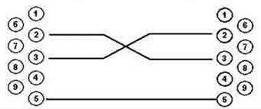
DB-9 socket DB-9 socket
LTP-4/8X rev.C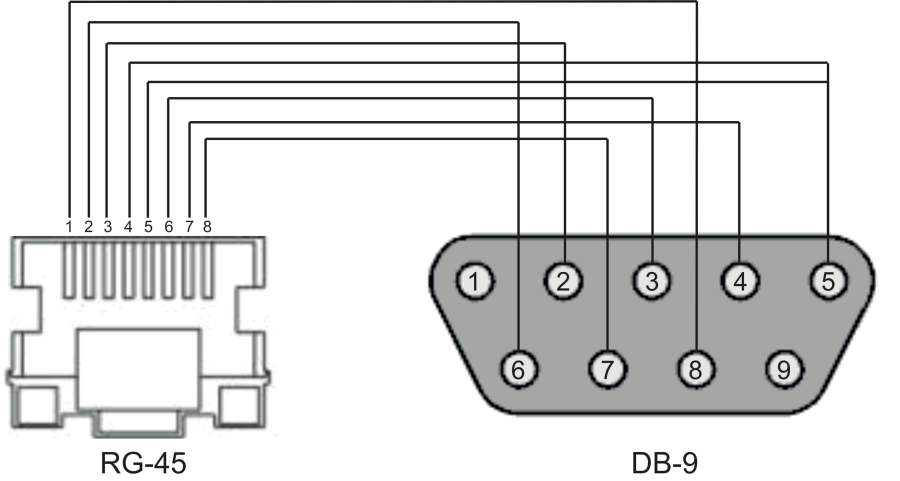
Appendix D. ONT NTU-1 configuration
Objective:
Configure the terminal in bridge mode, data transmission to the ONT side will be carried out in VLAN 2149.
Solution
A distinctive feature of ONT NTU-1 is its operation only in bridge mode; full configuration is performed by OLT using OMCI protocol without using an ACS server.
Add the required VLAN to the LTP switch configuration.
Switch to the SWITCH mode
LTP-X# switch

SWITCH configuration mode
LTP-X(switch)# configure

Add the required VLAN
LTP-X(switch)(config)# vlan 2149

Receive traffic in VLAN from front-port 0
LTP-X(switch)(config-vlan)# tagged front-port 0

Transmit tagged to all pon ports*
LTP-X(switch)(config-vlan)# tagged pon-port 0 – 7
LTP-X(switch)(config-vlan)# exit

Apply the configuration
LTP-X(switch)(config)# commit
LTP-X(switch)(config)# exit
LTP-X(switch)# exit
* Command is applicable for:
LTP-8Х rev.B HW_revision 2vХ.
LTP-8Х rev.С HW_revision 1vХ.
For LTP-8X HW_revision 1vX version, the following command applies: tagged pon-port 0 – 1 .
For LTP-4X rev.B, the following command applies: tagged pon-port 0 – 3.
Cross-connect and Ports profile configuration
Switch to the configuration mode
LTP-X# configure terminal

Create and switch to the Cross-Connect profile for NTU-1
LTP-X(config)# profile cross-connect NTU1

Specify the bridge operation mode
LTP-X(config-cross-connect)("NTU1")# bridge

Assign this Cross-connect to the bridge group 20
LTP-X(config-cross-connect)("NTU1")# bridge group 20
Specify the service VLAN for this service
LTP-X(config-cross-connect)("NTU1")# outer vid 2149
LTP-X(config-cross-connect)("NTU1")# exit

Create and switch to the profile for NTU-1
LTP-X(config)# profile ports NTU1

Add the port 0 in bridge group 20
LTP-X(config-ports)("NTU1")# port 0 bridge group 20

Apply the configuration
LTP-X(config-ports)("NTU1")# do commit

Save the configuration
LTP-X(config-ports)("NTU1")# do save
Adding and configuring ONT NTU-1.
Switch to the configuration mode
LTP-X# configure terminal

Switch to the tree 0 ONT ID 3
LTP-X(config)# interface ont 0/3

Assign the required ONT to this position
LTP-X(config)(if-ont-0/3)# serial 454C545862000078

Assign the ports profile to NTU-1
LTP-X(config)(if-ont-0/3)# profile ports NTU1

Assign the cross-connect profile to NTU-1
LTP-X(config)(if-ont-0/3)# service 0 profile cross-connect NTU1

Assign the default DBA profile
LTP-X(config)(if-ont-0/3)# service 0 profile dba dba-00

Apply the configuration
LTP-X(config)(if-ont-0/3)# do commit

Save the configuration
LTP-X(config)(if-ont-0/3)# do save
Configuration example for transmitting multiple VLANs in TRUNK mode via ONT NTU-1.
In the current firmware version, it is possible to transmit up to 8 VLANs in trunk mode via ONT NTU-1.
In the example, transmission of VLANs 100 and 200 will be considered.
Add the required VLAN to the LTP switch configuration.
Switch to the SWITCH mode
LTP-X# switch

SWITCH configuration mode
LTP-X(switch)# configure
Add the required VLAN
LTP-X(switch)(config)# vlan 100,200

Receive traffic in VLAN from front-port 0
LTP-X(switch)(config-vlan)# tagged front-port 0

Transmit tagged to all pon ports*
LTP-X(switch)(config-vlan)# tagged pon-port 0 – 7
LTP-X(switch)(config-vlan)# exit

Apply the configuration
LTP-X(switch)(config)# commit
LTP-X(switch)(config)# exit
LTP-X(switch)# exit
* Command is applicable for:
LTP-8Х rev.B HW_revision 2vХ.
LTP-8Х rev.С HW_revision 1vХ.
For LTP-8X HW_revision 1vX version, the following command applies: tagged pon-port 0 – 1 .
For LTP-4X rev.B, the following command applies: tagged pon-port 0 – 3.
Cross-connect and Ports profile configuration
Switch to the configuration mode
LTP-X# configure terminal

Create and switch to the Cross-Connect profile for NTU-1
LTP-X(config)# profile cross-connect NTU100

Specify the bridge operation mode
LTP-X(config-cross-connect)("NTU100")# bridge

Assign this Cross-connect to the bridge group 20
LTP-X(config-cross-connect)("NTU100")# bridge group 20

Specify the service VLAN for this service
LTP-X(config-cross-connect)("NTU100")# outer vid 100

Specify the user VLAN for this service
LTP-X(config-cross-connect)("NTU100")# user vid 100
LTP-X(config-cross-connect)("NTU100")# exit

Create and switch to the Cross-Connect profile for NTU-1
LTP-X(config)# profile cross-connect NTU200

Assign this Cross-connect to the bridge group 20
LTP-X(config-cross-connect)("NTU200")# bridge group 20

Specify the service VLAN for this service
LTP-X(config-cross-connect)("NTU200")# outer vid 200

Specify the user VLAN for this service
LTP-X(config-cross-connect)("NTU200")# user vid 200
LTP-X(config-cross-connect)("NTU200")# exit
Create and switch to the profile for NTU-1
LTP-X(config)# profile ports NTU1

Add the port 0 in bridge group 20
LTP-X(config-ports)("NTU1")# port 0 bridge group 20

Apply the configuration
LTP-X(config-ports)("NTU1")# do commit

Save the configuration
LTP-X(config-ports)("NTU1")# do save
Adding and configuring ONT NTU-1.
Switch to the configuration mode
LTP-X# configure terminal

Switch to the tree 0 ONT ID 3
LTP-X(config)# interface ont 0/3

Assign the required ONT to this position
LTP-X(config)(if-ont-0/3)# serial 454C545862000078

Assign the ports profile to NTU1
LTP-X(config)(if-ont-0/3)# profile ports NTU1

Assign the cross-connect profile to NTU-1
LTP-X(config)(if-ont-0/3)# service 0 profile cross-connect NTU100

Assign the default DBA profile
LTP-X(config)(if-ont-0/3)# service 0 profile dba dba-00

Assign the cross-connect profile to NTU-1
LTP-X(config)(if-ont-0/3)# service 1 profile cross-connect NTU200

Assign the default DBA profile
LTP-X(config)(if-ont-0/3)# service 1 profile dba dba-00

Apply the configuration
LTP-X(config)(if-ont-0/3)# do commit
APPENDIX E. ONT SFP-ONU configuration
Objective:
Configure the terminal in bridge mode, data transmission to the ONT side will be carried out in VLAN 2149.
Solution
A distinctive feature of ONT SFP-ONU is its operation only in bridge mode; full configuration is performed by OLT using OMCI protocol without using an ACS server.
Add the required VLAN to the LTP switch configuration.
Switch to the SWITCH mode
LTP-X# switch

SWITCH configuration mode
LTP-X(switch)# configure

Add the required VLAN
LTP-X(switch)(config)# vlan 2149

Receive traffic in VLAN from front-port 0
LTP-X(switch)(config-vlan)# tagged front-port 0

Transmit tagged to all pon ports*
LTP-X(switch)(config-vlan)# tagged pon-port 0 – 7
LTP-X(switch)(config-vlan)# exit

Apply the configuration
LTP-X(switch)(config)# commit
LTP-X(switch)(config)# exit
LTP-X(switch)# exit
* Command is applicable for:
LTP-8Х rev.B HW_revision 2vХ.
LTP-8Х rev.С HW_revision 1vХ.
For LTP-8X HW_revision 1vX version, the following command applies: tagged pon-port 0 – 1 .
For LTP-4X rev.B, the following command applies: tagged pon-port 0 – 3.
Cross-connect and Ports profile configuration
Switch to the configuration mode
LTP-X# configure terminal

Create and switch to the Cross-Connect profile for NTU-1
LTP-X(config)# profile cross-connect SFP

Specify the bridge operation mode
LTP-X(config-cross-connect)("NTU1")# bridge

Assign this Cross-connect to the bridge group 20
LTP-X(config-cross-connect)("NTU1")# bridge group 20
Specify the service VLAN for this service
LTP-X(config-cross-connect)("NTU1")# outer vid 2149
LTP-X(config-cross-connect)("NTU1")# exit

Create and switch to the profile for SFP-ONU
LTP-X(config)# profile ports SFPONU

Add the port 0 in bridge group 20
LTP-X(config-ports)("NTU1")# port 0 bridge group 20

Apply the configuration
LTP-X(config-ports)("NTU1")# do commit

Save the configuration
LTP-X(config-ports)("NTU1")# do save
Adding and configuring ONT SFP-ONU.
Switch to the configuration mode
LTP-X# configure terminal

Switch to the tree 0 ONT ID 3
LTP-X(config)# interface ont 0/3

Assign the required ONT to this position
LTP-X(config)(if-ont-0/3)# serial 454C545862000078

Assign the ports profile to SFPONU
LTP-X(config)(if-ont-0/3)# profile ports SFPONU

Assign the cross-connect profile to SFP-ONU
LTP-X(config)(if-ont-0/3)# service 0 profile cross-connect SFP

Assign the default DBA profile
LTP-X(config)(if-ont-0/3)# service 0 profile dba dba-00

Apply the configuration
LTP-X(config)(if-ont-0/3)# do commit

Save the configuration
LTP-X(config)(if-ont-0/3)# do save
Configuration example for transmitting multiple VLANs in TRUNK mode via ONT SFP-ONU.
In the current firmware version, it is possible to transmit up to 8 VLANs in trunk mode via ONT SFP-ONU.
In the example, transmission of VLANs 100 and 200 will be considered.
Add the required VLAN to the LTP switch configuration.
Switch to the SWITCH mode
LTP-X# switch

SWITCH configuration mode
LTP-X(switch)# configure
Add the required VLAN
LTP-X(switch)(config)# vlan 100,200

Receive traffic in VLAN from front-port 0
LTP-X(switch)(config-vlan)# tagged front-port 0

Transmit tagged to all pon ports
LTP-X(switch)(config-vlan)# tagged pon-port 0 – 7
LTP-X(switch)(config-vlan)# exit

Apply the configuration
LTP-X(switch)(config)# commit
LTP-X(switch)(config)# exit
LTP-X(switch)# exit
Cross-connect and Ports profile configuration
Switch to the configuration mode
LTP-X# configure terminal

Create and switch to the Cross-Connect profile for SFP-ONU
LTP-X(config)# profile cross-connect SFP100

Specify the bridge operation mode
LTP-X(config-cross-connect)("SFP100")# bridge

Assign this Cross-connect to the bridge group 20
LTP-X(config-cross-connect)("SFP100")# bridge group 20

Specify the service VLAN for this service
LTP-X(config-cross-connect)("SFP100")# outer vid 100

Specify the user VLAN for this service
LTP-X(config-cross-connect)("SFP100")# user vid 100
LTP-X(config-cross-connect)("SFP100")# exit

Create and switch to the Cross-Connect profile for SFP-ONU
LTP-X(config)# profile cross-connect SFP200

Assign this Cross-connect to the bridge group 20
LTP-X(config-cross-connect)("SFP200")# bridge group 20

Specify the service VLAN for this service
LTP-X(config-cross-connect)("SFP200")# outer vid 200

Specify the user VLAN for this service
LTP-X(config-cross-connect)("SFP200")# user vid 200
LTP-X(config-cross-connect)("SFP200")# exit

Create and switch to the profile for SFP-ONU
LTP-X(config)# profile ports SFPONU

Add the port 0 in bridge group 20
LTP-X(config-ports)("SFPONU")# port 0 bridge group 20

Apply the configuration
LTP-X(config-ports)("SFPONU ")# do commit
Save the configuration
LTP-X(config-ports)("SFPONU ")# do save
Adding and configuring ONT SFP-ONU.
Switch to the configuration mode
LTP-X# configure terminal

Switch to the tree 0 ONT ID 3
LTP-X(config)# interface ont 0/3

Assign the required ONT to this position
LTP-X(config)(if-ont-0/3)# serial 454C545862000078

Assign the ports profile to SFPONU
LTP-X(config)(if-ont-0/3)# profile ports SFPONU

Assign the cross-connect profile to SFP-ONU
LTP-X(config)(if-ont-0/3)# service 0 profile cross-connect SFP100

Assign the default DBA profile
LTP-X(config)(if-ont-0/3)# service 0 profile dba dba-00

Assign the cross-connect profile to SFP-ONU
LTP-X(config)(if-ont-0/3)# service 1 profile cross-connect SFP200

Assign the default DBA profile
LTP-X(config)(if-ont-0/3)# service 1 profile dba dba-00

Apply the configuration
LTP-X(config)(if-ont-0/3)# do commit
Configuration example for transmission via ONT SFP-ONU VLANs in TRUNK mode, several VLANs in Selective-tunnel mode and other VLANs in Tunnel mode
In firmware versions older than 3.26.0, it is possible to organize the so-called trunk tunnel services through SFP-ONU.
VLAN 300 (multicast) and QinQ VLAN 1100 and 1200 (Internet) come to the uplink OLT. It is necessary to let them pass to the switch integrated in the OLT via SFP-ONU.
Consider the procedure of OLT configuration for the above diagram.
Step 1. Configure the switch.
LTP-X(switch)(config)# vlan 300,1100,1200
LTP-X(switch)(config-vlan-range)# tagged pon-port 0
LTP-X(switch)(config-vlan-range)# front-port 0
LTP-X(switch)(config-vlan-range)# commit
Step 2. Configure cross-connect profiles.
LTP-X(config)# profile cross-connect cc-tunnel
LTP-X(config-cross-connect)("cc-tunnel")# bridge
LTP-X(config-cross-connect)("cc-tunnel")# bridge group 10
LTP-X(config-cross-connect)("cc-tunnel")# tag-mode tunnel
LTP-X(config-cross-connect)("cc-tunnel")# exit
LTP-X(config)# profile cross-connect "cc-selecttunnel"
LTP-X(config-cross-connect)("cc-selecttunnel")# bridge
LTP-X(config-cross-connect)("cc-selecttunnel")# bridge group 10
LTP-X(config-cross-connect)("cc-selecttunnel")# tag-mode selective-tunnel
LTP-X(config-cross-connect)("cc-selecttunnel")# exit
LTP-X(config)# profile cross-connect "cc-single"
LTP-X(config-cross-connect)("cc-single")# bridge
LTP-X(config-cross-connect)("cc-single")# bridge group 10
LTP-X(config-cross-connect)("cc-single")# user vid 300
LTP-X(config-cross-connect)("cc-single")# exit
Step 3. Configure ports profiles.
LTP-X(config)# profile ports bridge-10
LTP-X(config-ports)("bridge-10")# port 0 bridge group 10
Step 4. Set up the address-table profile by specifying the VLANs used for tunnels and assign the profile to GPON ports.
LTP-X(config)# profile address-table at-tunnel
LTP-X(config-address-table)("at-tunnel")# s-vlan 1100 use c-vlan
LTP-X(config-address-table)("at-tunnel")# s-vlan 1200 use c-vlan
LTP-X(config-address-table)("at-tunnel")# exit
LTP-X(config)# interface gpon-port 0
LTP-X(config)(if-gpon-0)# profile address-table at-tunnel
Step 5. Set up the SFP-ONU to be used for switch connection.
LTP-X(config)# interface ont 0/0
LTP-X(config)(if-ont-0/0)# serial "454C545300000001"
LTP-X(config)(if-ont-0/0)# service 0 profile cross-connect cc-tunnel dba dba-00
LTP-X(config)(if-ont-0/0)# service 1 profile cross-connect cc-selecttunnel dba dba-00
LTP-X(config)(if-ont-0/0)# service 2 profile cross-connect cc-single dba dba-00
LTP-X(config)(if-ont-0/0)# profile ports "bridge-10"
LTP-X(config)(if-ont-0/0)# service 0 custom svid 1100
LTP-X(config)(if-ont-0/0)# service 1 custom svid 1200
LTP-X(config)(if-ont-0/0)# service 1 selective-tunnel uvid 201-203
LTP-X(config)(if-ont-0/0)# service 2 custom svid 300
APPENDIX F. ONT/GPON interface status table
ONT status description
ONT status | Description |
|---|---|
UNACTIVATED | ONT has no configurations |
ALLOCATED | ONT detected |
AUTHINPROGRESS | ONT authentication is in progress |
AUTHFAILED | Authentication failed |
AUTHOK | Authentication successfully completed |
PRECONFIG | Preparing ONT for configuration |
CFGINPROGRESS | ONT configuration is in progress |
CFGFAILED | Configuration failed |
OK | ONT is in operation |
BLOCKED | ONT is blocked |
MIBRESET | ONT MIB reset |
FAILED | ONT has a critical failure |
FWUPDATING | ONT firmware update is in progress |
DISABLED | ONT is disabled (technically blocked) |
GPON interface states
Value | Description |
|---|---|
INITED | The channel is initialised |
CFGINPROGRESS | The channel configuration is in progress |
CFGFAILED | The channel configuration completed with error |
OK | The channel is in operation |
FAILED | The channel is out of operation |
DISABLED | The channel is disabled |