Introduction
This manual describes the main provisions and principles of forming acs profile for configuring GPON NTU-RG-54xx and NTU-52V ELTEX subscriber terminals on foirmware version 1.1.x or 1.2.x.
Only the parameters and their values are listed in this manual. If you are using an external ACS server, it is enough to add only these settings to your profile. In case you use the built-in ACS server, you need to add the set property (before parameter) and nocheck (after parameter value) expressions to your profile for all parameters.
Example:
set property "InternetGatewayDevice.Layer2Bridging.Bridge.2.BridgeEnable" "1" nocheck
set property "InternetGatewayDevice.Layer2Bridging.Bridge.2.BridgeName" "eltex_default" nocheck
set property "InternetGatewayDevice.Layer2Bridging.Bridge.2.VLANID" "10" nocheck
Default ONT configuration
Before proceeding to acs profiling, let's look at the default configuration of ONT using the example of NTU-RG-5402G-W subscriber terminal. Each default configuration block will be discussed below.
Bridge 1 for NTU-RG-54xx and NTU-52V for versions 1.1.X and above is reserved for TR-069 interface. The following bridges are created for services. To create a Bridge you need to add the following parameters to your profile.
To create a Bridge for TR-069:
"InternetGatewayDevice.Layer2Bridging.Bridge.1.BridgeEnable" "1"
"InternetGatewayDevice.Layer2Bridging.Bridge.1.BridgeName" "TR-HSI"
The following Bridges for services are numbered in order:
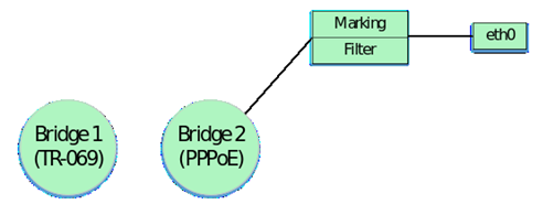
This block of parameters in our configuration forms two Bridge groups – Bridge 1 (TR-069) and Bridge 2 (Internet).

The eth0 interface is then binded to Bridge 2:
"InternetGatewayDevice.Layer2Bridging.Marking.1.MarkingEnable" "1"
"InternetGatewayDevice.Layer2Bridging.Marking.1.MarkingInterface" "1"
"InternetGatewayDevice.Layer2Bridging.Marking.1.MarkingBridgeReference" "1"

"InternetGatewayDevice.Layer2Bridging.Filter.1.FilterEnable" "1"
"InternetGatewayDevice.Layer2Bridging.Filter.1.FilterInterface" "1"
"InternetGatewayDevice.Layer2Bridging.Filter.1.FilterBridgeReference" "1"
At this stage, you should pay attention to the following parameters:
"InternetGatewayDevice.Layer2Bridging.Marking.1.MarkingBridgeReference" "1"
"InternetGatewayDevice.Layer2Bridging.Marking.1.MarkingInterface" "1"
"InternetGatewayDevice.Layer2Bridging.Filter.1.FilterBridgeReference" "1"
"InternetGatewayDevice.Layer2Bridging.Filter.1.FilterInterface" "1"
The Filter and Marking parameters are responsible for binding the interface to the group (in this case eth0 to Bridge 2). The Filter parameter enables incoming traffic and Marking – outgoing traffic.
"InternetGatewayDevice.Layer2Bridging.Marking.1.MarkingBridgeReference" "1" – creates Marking.1 – bind local eth0 interface to Bridge 2 for outgoing traffic. The number of the bridge to which the interface is bound is set by the "MarkingBridgeReference" parameter value. When binding interfaces to Bridge groups, the numbering of MarkingBridgeReference groups starts with 0. Thus, at value MarkingBridgeReference 0 the binding to Bridge 1 is performed. But Bridge 1 is reserved for the TR interface. This bridge should not be bound to the interfaces. Therefore, the values of these parameters begin with 1, which corresponds to the binding of the local interface to Bridge 2.
"InternetGatewayDevice.Layer2Bridging.Marking.1.MarkingInterface" "1" – this parameter specifies the number of the local interface eth0, which is bound by the marking (Marking 1) to Bridge 2.
"InternetGatewayDevice.Layer2Bridging.Filter.1.FilterBridgeReference" "1" – this parameter generates bindings of the local interface to Bridge 2 for outgoing traffic. The values are specified in the same way as for MarkingBridgeReference.
"InternetGatewayDevice.Layer2Bridging.Filter.1.FilterInterface" "1" – this parameter is used to bind the local eth0 interface to Bridge 2.
After binding eth0 to Br.1 we get the following construction:
Default interface numbering, markings and filters must be followed to create a correctly working acs profile. Strict correspondence between markings, filters and local interfaces must also be observed.
Numbering and matching of local interfaces to filters and markings for ONT NTU-RG-54xx and NTU-52V are given further in tables 1.1, 1.2 and 1.3.
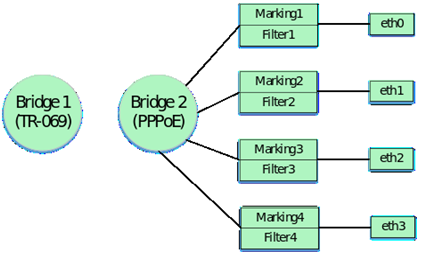
The following parameters bind local interfaces eth1, eth2 and eth3 to the Bridge by analogy with eth0.
"InternetGatewayDevice.Layer2Bridging.Marking.2.MarkingEnable" "1"
"InternetGatewayDevice.Layer2Bridging.Marking.2.MarkingInterface" "2"
"InternetGatewayDevice.Layer2Bridging.Marking.2.MarkingBridgeReference" "1"

"InternetGatewayDevice.Layer2Bridging.Filter.2.FilterEnable" "1"
"InternetGatewayDevice.Layer2Bridging.Filter.2.FilterInterface" "2"
"InternetGatewayDevice.Layer2Bridging.Filter.2.FilterBridgeReference" "1"

"InternetGatewayDevice.Layer2Bridging.Marking.3.MarkingEnable" "1"
"InternetGatewayDevice.Layer2Bridging.Marking.3.MarkingInterface" "3"
"InternetGatewayDevice.Layer2Bridging.Marking.3.MarkingBridgeReference" "1"

"InternetGatewayDevice.Layer2Bridging.Filter.3.FilterEnable" "1"
"InternetGatewayDevice.Layer2Bridging.Filter.3.FilterInterface" "3"
"InternetGatewayDevice.Layer2Bridging.Filter.3.FilterBridgeReference" "1"

"InternetGatewayDevice.Layer2Bridging.Marking.4.MarkingEnable" "1"
"InternetGatewayDevice.Layer2Bridging.Marking.4.MarkingInterface" "4"
"InternetGatewayDevice.Layer2Bridging.Marking.4.MarkingBridgeReference" "1"

"InternetGatewayDevice.Layer2Bridging.Filter.4.FilterEnable" "1"
"InternetGatewayDevice.Layer2Bridging.Filter.4.FilterInterface" "4"
"InternetGatewayDevice.Layer2Bridging.Filter.4.FilterBridgeReference" "1"
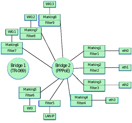
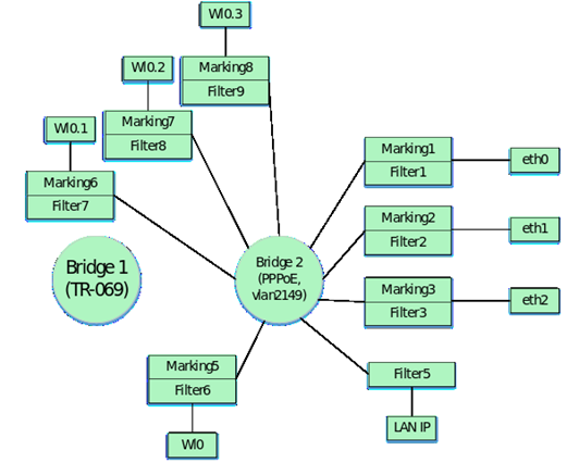
So, after binding the four interfaces to the second bridge, we have the following schematic design:
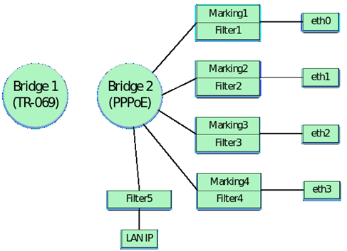
Next, in the profile, the Bridge is bound to the LAN IP interface of the ONT. Please note that this binding is done with filters only, no marking is used in this case. Binding is performed to the Bridge group by default, in our case it is Bridge 2. For LAN IP interface 6 ONT interface is used by default. The parameters with which the binding is performed:
"InternetGatewayDevice.Layer2Bridging.Filter.5.FilterBridgeReference" "1"
"InternetGatewayDevice.Layer2Bridging.Filter.5.FilterEnable" "1"
"InternetGatewayDevice.Layer2Bridging.Filter.5.FilterInterface" "6"
The following parameters specify the settings for the LAN IP interface:
"InternetGatewayDevice.LANDevice.1.LANHostConfigManagement.IPInterface.1.Enable" "1"

"InternetGatewayDevice.LANDevice.1.LANHostConfigManagement.IPInterface.1.IPInterfaceAddressingType" "Static"

"InternetGatewayDevice.LANDevice.1.LANHostConfigManagement.IPInterface.1.IPInterfaceIPAddress" "192.168.1.1"

"InternetGatewayDevice.LANDevice.1.LANHostConfigManagement.IPInterface.1.IPInterfaceSubnetMask" "255.255.255.0"

"InternetGatewayDevice.LANDevice.1.LANHostConfigManagement.MinAddress" "192.168.1.20"

"InternetGatewayDevice.LANDevice.1.LANHostConfigManagement.MaxAddress" "192.168.1.100"

"InternetGatewayDevice.LANDevice.1.LANHostConfigManagement.SubnetMask" "255.255.255.0"

"InternetGatewayDevice.LANDevice.1.LANHostConfigManagement.DHCPLeaseTime" "3600"
Consider in detail what each of these parameters configures:
"InternetGatewayDevice.LANDevice.1.LANHostConfigManagement.IPInterface.1.Enable" – enables IP interface LAN.
"InternetGatewayDevice.LANDevice.1.LANHostConfigManagement.IPInterface.1.IPInterfaceAddressingType" – specifying that the way the address is set on the interfacing is static.
"InternetGatewayDevice.LANDevice.1.LANHostConfigManagement.IPInterface.1.IPInterfaceIPAddress" – specifies the default 192.168.1.1 address to access the LAN IP ONT from the local network.
"InternetGatewayDevice.LANDevice.1.LANHostConfigManagement.IPInterface.1.IPInterfaceSubnetMask" – this parameter defines the subnetwork mask for LAN IP.
"InternetGatewayDevice.LANDevice.1.LANHostConfigManagement.MinAddress" – this parameter is used to specify the lower bound of the address range that the DHCP server ONT will distribute on the local network.
"InternetGatewayDevice.LANDevice.1.LANHostConfigManagement.MaxAddress" – this parameter is used to specify the upper bound of the address range that the DHCP server ONT will distribute on the local network.
"InternetGatewayDevice.LANDevice.1.LANHostConfigManagement.SubnetMask" – this parameter defines the subnet mask for which the DHCP server will issue IP addresses.
"InternetGatewayDevice.LANDevice.1.LANHostConfigManagement.DHCPLeaseTime" – specifies the lease time of addresses issued by the ONT DHCP server on the local network.
By including the IP interface in the LAN configuration, we obtain the following logical structure:
Then, by analogy with binding the interfaces eth0 - eth3 to Bridge 2, the interface wl0 (wi-fi interface) is binded.
"InternetGatewayDevice.Layer2Bridging.Marking.5.EthernetPriorityMark" "0"
"InternetGatewayDevice.Layer2Bridging.Marking.5.MarkingBridgeReference" "1"
"InternetGatewayDevice.Layer2Bridging.Marking.5.MarkingEnable" "TRUE"
"InternetGatewayDevice.Layer2Bridging.Marking.5.MarkingInterface" "7"

"InternetGatewayDevice.Layer2Bridging.Filter.6.FilterEnable" "1"
"InternetGatewayDevice.Layer2Bridging.Filter.6.FilterInterface" "7"
"InternetGatewayDevice.Layer2Bridging.Filter.6.FilterBridgeReference" "1"
After adding the wl0 interface, the configuration will look like this:
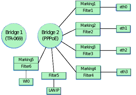
Interfaces with numbers 7, 8, 9 and 10 correspond to the wi-fi interfaces. Accordingly, wl0 is the interface for the primary Wi-Fi network (7), and wl0.1 (8), wl0.2 (9), wl0.3 (10) are the interfaces for guest Wi-Fi networks.
To configure this interfaces you need to add the following parameters to your profile:
"InternetGatewayDevice.Layer2Bridging.Marking.6.MarkingEnable" "1"
"InternetGatewayDevice.Layer2Bridging.Marking.6.MarkingInterface" "8"
"InternetGatewayDevice.Layer2Bridging.Marking.6.MarkingBridgeReference" "1"

"InternetGatewayDevice.Layer2Bridging.Filter.7.FilterEnable" "1"
"InternetGatewayDevice.Layer2Bridging.Filter.7.FilterInterface" "8"
"InternetGatewayDevice.Layer2Bridging.Filter.7.FilterBridgeReference" "1"

"InternetGatewayDevice.Layer2Bridging.Marking.7.MarkingEnable" "1"
"InternetGatewayDevice.Layer2Bridging.Marking.7.MarkingInterface" "9"
"InternetGatewayDevice.Layer2Bridging.Marking.7.MarkingBridgeReference" "1"

"InternetGatewayDevice.Layer2Bridging.Filter.8.FilterEnable" "1"
"InternetGatewayDevice.Layer2Bridging.Filter.8.FilterInterface" "9"
"InternetGatewayDevice.Layer2Bridging.Filter.8.FilterBridgeReference" "1"

"InternetGatewayDevice.Layer2Bridging.Marking.8.MarkingEnable" "1"
"InternetGatewayDevice.Layer2Bridging.Marking.8.MarkingInterface" "10"
"InternetGatewayDevice.Layer2Bridging.Marking.8.MarkingBridgeReference" "1"

"InternetGatewayDevice.Layer2Bridging.Filter.9.FilterEnable" "1"
"InternetGatewayDevice.Layer2Bridging.Filter.9.FilterInterface" "10"
"InternetGatewayDevice.Layer2Bridging.Filter.9.FilterBridgeReference" "1"
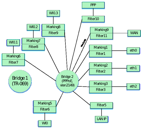
By including this interfaces in the configuration, we obtain the following logical structure:
Finally you should configure the parameters that bind WAN Virtual Interface IP to Bridge 2. In versions 1.1.X and 1.2.X an additional filter is also used to bind the WAN interface to the Bridge.
"InternetGatewayDevice.Layer2Bridging.Filter.11.FilterEnable" "1"
"InternetGatewayDevice.Layer2Bridging.Filter.11.FilterInterface" "5"
"InternetGatewayDevice.Layer2Bridging.Filter.11.FilterBridgeReference" "1"

"InternetGatewayDevice.Layer2Bridging.Filter.10.FilterEnable" "1"
"InternetGatewayDevice.Layer2Bridging.Filter.10.FilterInterface" "12"
"InternetGatewayDevice.Layer2Bridging.Filter.10.FilterBridgeReference" "1"

"InternetGatewayDevice.Layer2Bridging.Marking.9.MarkingEnable" "1"
"InternetGatewayDevice.Layer2Bridging.Marking.9.MarkingInterface" "5"
"InternetGatewayDevice.Layer2Bridging.Marking.9.MarkingBridgeReference" "1"
"InternetGatewayDevice.Layer2Bridging.Marking.9.VLANIDMark" "10"
"InternetGatewayDevice.Layer2Bridging.Marking.9.VLANIDUntag" "0"
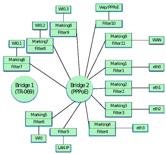
Note that the local WAN IP interface number has the number 5 in the default interface numbering. There is also a difference between the order numbers of the markings and filters in the given parameters. This difference is not an error. Filter and marking numbers may not match. It is important that the general sequential numbering for filters and markings is maintained when creating the profile. Also note that for the additional Filter.10.FilterInterface filter, the value is 12. In the default configuration for NTU-RG-5402G-W the last value of the interface is 10. The following interface is highlighted for TR-069 (similar to NTU-RG-54xx and NTU-52V/VC). Therefore, binding the WAN interface starts with the following value.
Thus, the default configuration has the following schematic view:
The following table shows the sequence numbers of the markings and filters and the sequence numbers of the main ONT configuration interfaces NTU-RG-5402G-W, NTU-RG-5421G-Wac and NTU-52V/VC by default for versions 1.1.X and 1.2.X.
Table 1.1 Numbering of main interfaces and sequence numbers of markings and filters in the configuration for the NTU-RG-5402G-W by default
Interface | Marking | Filtering | Marking Interface | Filtering Interface | Bridge |
|---|---|---|---|---|---|
Eth0 | 1 | 1 | 1 | 1 | 1 |
Eth1 | 2 | 2 | 2 | 2 | 1 |
Eth2 | 3 | 3 | 3 | 3 | 1 |
Eth3 | 4 | 4 | 4 | 4 | 1 |
LAN IP | - | 5 | - | 6 | 1 |
Wl0 | 5 | 6 | 7 | 7 | 1 |
Wl0.1 | 6 | 7 | 8 | 8 | 1 |
Wl0.2 | 7 | 8 | 9 | 9 | 1 |
Wl0.3 | 8 | 9 | 10 | 10 | 1 |
WAN | 9 | 11 | 5 | 5 | 1 |
TR IPoE | - | - | - | 11 | 0 |
The default sequence numbers of markers and filters, as well as the sequence numbers of the main interfaces in the ONT NTU-RG-5421G-Wac configuration are shown in Table 1.2.
Table 1.2 Numbering of main interfaces and sequence numbers of markings and filters in the configuration for the NTU-RG-5421G-Wac by default.
Interface | Marking | Filtering | Marking Interface | Filtering Interface | Bridge |
|---|---|---|---|---|---|
Eth0 | 1 | 1 | 1 | 1 | 1 |
Eth1 | 2 | 2 | 2 | 2 | 1 |
Eth2 | 3 | 3 | 3 | 3 | 1 |
Eth3 | 4 | 4 | 4 | 4 | 1 |
LAN IP | - | 5 | - | 6 | 1 |
Wl0 | 5 | 6 | 7 | 7 | 1 |
Wl0.1 | 6 | 7 | 8 | 8 | 1 |
Wl0.2 | 7 | 8 | 9 | 9 | 1 |
Wl0.3 | 8 | 9 | 10 | 10 | 1 |
Wl1 | 9 | 10 | 11 | 11 | 1 |
Wl1.1 | 10 | 11 | 12 | 12 | 1 |
Wl1.2 | 11 | 12 | 13 | 13 | 1 |
Wl1.3 | 12 | 13 | 14 | 14 | 1 |
WAN | 13 | 15 | 5 | 5 | 1 |
TR IPoE | - | - | - | 15 | 0 |
The default sequence numbers of markers and filters, as well as the sequence numbers of the main interfaces in the ONT NTU-52V/VC configuration are shown in Table 1.3
Table 1.3 Numbering of main interfaces and sequence numbers of markings and filters in the configuration for the NTU-RG-52V/VC by default.
Interface | Marking | Filtering | Marking Interface | Filtering Interface | Bridge |
|---|---|---|---|---|---|
Eth0 | 1 | 1 | 1 | 1 | 1 |
Eth1 | 2 | 2 | 2 | 2 | 1 |
WAN | 3 | 4 | 3 | 3 | 1 |
LAN IP | - | 4 | - | 4 | 1 |
TR IPoE | - | - | - | 5 | 0 |
Profile creation example for ONT NTU-RG-5402G-W
Let's consider the process of profiling acs for NTU-RG-5402G-W subscriber terminal where it is required to raise the PPP client and transfer traffic from it to the subscriber equipment located behind NAT ONT on 0.1 and 2 ports in vlan 2149. It is necessary that the IGMP Proxy ONT work in 30 vlan. It is also necessary to organize the obtaining of IP-address on IP-TV media player (STB) on port 3 ONT in vlan 2349 and IP-telephony in vlan 3149.
When creating this profile, we will proceed from the ONT NTU-RG-5402G-W default configuration discussed earlier.
It should be noted that there was only one Bridge in the default configuration. When profiling the acs, you should be guided by the fact that for each service (service) you need to create a separate bridge.
Let's proceed with the profile description.
First create Bridge for TR interface. For this purpose, add to the profile:
"InternetGatewayDevice.Layer2Bridging.Bridge.1.BridgeEnable" "1"
"InternetGatewayDevice.Layer2Bridging.Bridge.1.BridgeName" "TR-HSI"
Then create Bridge 2 for PPPoE:
"InternetGatewayDevice.Layer2Bridging.Bridge.2.BridgeEnable" "1" - make the first bridge active with a value of "1".
"InternetGatewayDevice.Layer2Bridging.Bridge.2.BridgeName" "PPPoE" - specify the Bridge 1 name with the value "PPPoE" (name can be any).
"InternetGatewayDevice.Layer2Bridging.Bridge.2.VLANID" "2149" - specify in which VLAN the PPP client should work with VLANID "2149".
After creating a Bridge for PPPoE, we will bind it to the LAN interfaces. For Bridge 1 TR-069, bindings to ONT interfaces are not required.
"InternetGatewayDevice.Layer2Bridging.Filter.1.FilterEnable" "1" - enable the Filter 1 with a value of "1".
"InternetGatewayDevice.Layer2Bridging.Filter.1.FilterInterface" "1" - this parameter binds the eth0 interface, which in the model defaults to "FilterInterface" "1" to Bridge 2.
"InternetGatewayDevice.Layer2Bridging.Filter.1.FilterBridgeReference" "1" - assign Filter 1 to Bridge 2 with parameter FilterBridgeReference" "1".
Thus, we associated or bound the eth0 interface to the second bridge for incoming traffic. Next, you need to do the same only for outgoing traffic using Marking. For this you should add parameters to your profile:
"InternetGatewayDevice.Layer2Bridging.Marking.1.MarkingEnable" "1" - enable Marking 1 with a value of "1".
"InternetGatewayDevice.Layer2Bridging.Filter.1.MarkingInterface" "1" - this parameter binds the eth0 interface, which in the model defaults to "MarkingInterface" "1" to Bridge 2.
"InternetGatewayDevice.Layer2Bridging.Marking.1.MarkingBridgeReference" "1" - assign Marking 1 to Bridge 2 with MarkingBridgeReference parameter "1".
The following acs parameters will bind the eth1 and eth2 interfaces to Bridge 2 for both incoming and outgoing traffic. Acs parameters will be used the same as in the case of binding eth0 to Bridge 2 only with the corresponding interface numbering, so we will not consider the value of each acs parameter separately.
"InternetGatewayDevice.Layer2Bridging.Filter.2.FilterEnable" "1"
"InternetGatewayDevice.Layer2Bridging.Filter.2.FilterInterface" "2"
"InternetGatewayDevice.Layer2Bridging.Filter.2.FilterBridgeReference" "1"

"InternetGatewayDevice.Layer2Bridging.Marking.2.MarkingEnable" "1"
"InternetGatewayDevice.Layer2Bridging.Marking.2.MarkingInterface" "2"
"InternetGatewayDevice.Layer2Bridging.Marking.2.MarkingBridgeReference" "1"

"InternetGatewayDevice.Layer2Bridging.Filter.3.FilterEnable" "1"
"InternetGatewayDevice.Layer2Bridging.Filter.3.FilterInterface" "3"
"InternetGatewayDevice.Layer2Bridging.Filter.3.FilterBridgeReference" "1"

"InternetGatewayDevice.Layer2Bridging.Marking.3.MarkingEnable" "1"
"InternetGatewayDevice.Layer2Bridging.Marking.3.MarkingInterface" "3"
"InternetGatewayDevice.Layer2Bridging.Marking.3.MarkingBridgeReference" "1"
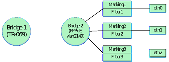
The acs parameters listed above align the ONT logic blocks as follows:
Since it is necessary to configure the obtaining of IP address for STB in vlan 2349 behind the ONT eth3 port, it is necessary to create a new bridge for this service, observing the general numbering of bridges in the profile. Bridge 5 will be created for the STB and a fourth ONT port will be attached to this bridge. These settings will be considered later. It was previously specified that the default numbering of markers, filters and main interfaces should be used when profiling.
Marking 4 and Filter 4 are used to bind eth3 to a bridge, and eth3 itself is interpreted as FilterInterface 4 in acs.
In order not to lose the sequence of forming the logical structure of ONT, let's consider binding the remaining interfaces to Bridge 2. Therefore, the further numbering of the markings and filters is saved and continues from 5.
The following parameters bind to Bridge 2 of the LAN IP interface. This interface has a FilterInterface 6 value in the ACS interpretation (for NTU-RG-5421G-Wac and NTU-52V/VC see Tables 1.2 and 1.3 respectively). An important feature is that only the Filter is used when binding a LAN IP to the bridge. You do not need to use Marking in this case.
"InternetGatewayDevice.Layer2Bridging.Filter.5.FilterBridgeReference" "1"
"InternetGatewayDevice.Layer2Bridging.Filter.5.FilterEnable" "1"
"InternetGatewayDevice.Layer2Bridging.Filter.5.FilterInterface" "6"
After binding the LAN IP interface to the bridge, set the parameters for the LAN IP. This can be done using the following ACS parameters:
"InternetGatewayDevice.LANDevice.1.LANHostConfigManagement.IPInterface.1.Enable" "1" – enabling the LAN interface with the value "1". To disable use the value "0".
"InternetGatewayDevice.LANDevice.1.LANHostConfigManagement.IPInterface.1.IPInterfaceAddressingType" "Static" – specifies the method of setting the address of the LAN interface. In this case "Static" is specified.
"InternetGatewayDevice.LANDevice.1.LANHostConfigManagement.IPInterface.1.IPInterfaceIPAddress" "192.168.1.1" – this parameter sets the LAN interface the IP address 192.168.1.1 for access from the local network.
"InternetGatewayDevice.LANDevice.1.LANHostConfigManagement.IPInterface.1.IPInterfaceSubnetMask" "255.255.255.0" – this parameter sets the subnet mask for LAN, in this case /24.
"InternetGatewayDevice.LANDevice.1.LANHostConfigManagement.DHCPServerEnable" "1" – enabling the internal ONT DHCP server for LAN equipment. Value "1" – DHCP server enabled, value "0" – disabled.
"InternetGatewayDevice.LANDevice.1.LANHostConfigManagement.DHCPLeaseTime" "3600" – Specifies the lease time for IP addresses issued by the ONT DHCP server.
"InternetGatewayDevice.LANDevice.1.LANHostConfigManagement.MaxAddress" "192.168.1.100" – specifies the upper bound of the range of IP addresses issued by the ONT DHCP server.
"InternetGatewayDevice.LANDevice.1.LANHostConfigManagement.MinAddress" "192.168.1.20" – specifies the lower bound of the range of IP addresses issued by the ONT DHCP server.
"InternetGatewayDevice.LANDevice.1.LANHostConfigManagement.SubnetMask" "255.255.255.0" – This parameter defines the subnet mask in which the DHCP server will distribute addresses. In this case, the subnet with mask /24 is configured.
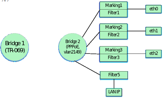
After binding the LAN IP interface we get the following logical ONT structure:
The following acs parameters bind the wi-fi interface Wl0 to the Bridge 2 for incoming and outgoing traffic.
Marking 5 and Filter 6 must be used to bind this interface to the Bridge. Wl0 in the acs interpretation has the value FilterInterface 7.
"InternetGatewayDevice.Layer2Bridging.Marking.5.EthernetPriorityMark" "0"
"InternetGatewayDevice.Layer2Bridging.Marking.5.MarkingBridgeReference" "1"
"InternetGatewayDevice.Layer2Bridging.Marking.5.MarkingEnable" "TRUE"
"InternetGatewayDevice.Layer2Bridging.Marking.5.MarkingInterface" "7"

"InternetGatewayDevice.Layer2Bridging.Filter.6.FilterEnable" "1"
"InternetGatewayDevice.Layer2Bridging.Filter.6.FilterInterface" "7"
"InternetGatewayDevice.Layer2Bridging.Filter.6.FilterBridgeReference" "1"
Once the main Wl0 interface is bound to Bridge 2, you must also bind to the guest Wi-Fi interfaces bridge. Do this by adding the following parameters to your profile:
"InternetGatewayDevice.Layer2Bridging.Filter.7.FilterEnable" "1"
"InternetGatewayDevice.Layer2Bridging.Filter.7.FilterInterface" "8"
"InternetGatewayDevice.Layer2Bridging.Filter.7.FilterBridgeReference" "1"

"InternetGatewayDevice.Layer2Bridging.Marking.6.MarkingEnable" "1"
"InternetGatewayDevice.Layer2Bridging.Marking.6.MarkingInterface" "8"
"InternetGatewayDevice.Layer2Bridging.Marking.6.MarkingBridgeReference" "1"

"InternetGatewayDevice.Layer2Bridging.Filter.8.FilterEnable" "1"
"InternetGatewayDevice.Layer2Bridging.Filter.8.FilterInterface" "9"
"InternetGatewayDevice.Layer2Bridging.Filter.8.FilterBridgeReference" "1"

"InternetGatewayDevice.Layer2Bridging.Marking.7.MarkingEnable" "1"
"InternetGatewayDevice.Layer2Bridging.Marking.7.MarkingInterface" "9"
"InternetGatewayDevice.Layer2Bridging.Marking.7.MarkingBridgeReference" "1"

"InternetGatewayDevice.Layer2Bridging.Filter.9.FilterEnable" "1"
"InternetGatewayDevice.Layer2Bridging.Filter.9.FilterInterface" "10"
"InternetGatewayDevice.Layer2Bridging.Filter.9.FilterBridgeReference" "1"

"InternetGatewayDevice.Layer2Bridging.Marking.8.MarkingEnable" "1"
"InternetGatewayDevice.Layer2Bridging.Marking.8.MarkingInterface" "10"
"InternetGatewayDevice.Layer2Bridging.Marking.8.MarkingBridgeReference" "1"
After binding the interfaces Wl0, Wl0.1, Wl0.2, Wl0.3 the logical structure of ONT will look like:
Next you need to bind the WAN-interface to Bridge2. WAN interface in the acs interpretation has the value FilterInterface 5 (for NTU-RG-5421G-Wac and NTU-52V/VC see Table 1.2 and 1.3 respectively). The Marking and Filter numbers for WAN-to-Bridge binding should be selected in order after the previous Marking and Filter numbers in the profile.
At this stage, the last numbers for Filter and Marking were 9 and 8 respectively. So we continue numbering for Marking number 9. Besides binding to the WAN interface bridge, it is also necessary to bind the PPP virtual interface to this bridge (the parameters will be given below). Binding of the PPP interface is done only with the filter. Under the rules, you must first bind the filter to the PPP interface and then to the WAN interface. Therefore, we will use Filter number 10 for binding the PPP interface and Filter number 11 for the WAN interface.
"InternetGatewayDevice.Layer2Bridging.Filter.11.FilterEnable" "1"
"InternetGatewayDevice.Layer2Bridging.Filter.11.FilterInterface" "5"
"InternetGatewayDevice.Layer2Bridging.Filter.11.FilterBridgeReference" "1"

"InternetGatewayDevice.Layer2Bridging.Marking.9.MarkingEnable" "1"
"InternetGatewayDevice.Layer2Bridging.Marking.9.MarkingInterface" "5"
"InternetGatewayDevice.Layer2Bridging.Marking.9.MarkingBridgeReference" "1"
"InternetGatewayDevice.Layer2Bridging.Marking.9.VLANIDMark" "2149"
"InternetGatewayDevice.Layer2Bridging.Marking.9.VLANIDUntag" "0"
InternetGatewayDevice.Layer2Bridging.Marking.9.VLANIDMark – pay attention to this parameter. When binding a WAN to a Bridge in Marking, the VLANIDMark parameter value must correspond to the vlan number of the Bridge to which the WAN is bound. In our case, vlan 2 is used for Bridge 1, so the VLANIDMark value is "2149".
Now it is necessary to bind to Bridge 2 the interface of PPP, to be able to raise the PPPoE session between the ONT and the ISP equipment in vlan 2149.
There is also a special feature here: as mentioned above, to bind service interfaces not by default (LAN interface exception) to breeches, you need to use only filters.
FilterInterface values for interfaces other than the default should be consecutive and start after the highest FilterInterface value in the default configuration. But the value 11 for NTU-RG-5402G-W is reserved in the default configuration for using the TR interface. Therefore, for services the FilterInterface value starts with the number of the last default FilterInterface value + 1. In our case, the highest FilterInterface value in the default configuration is 10 (Wl0.3 interface). Therefore, FilterInterface for the non-default first interface will be 12.
The following lines bind PPP to Bridge 2.
"InternetGatewayDevice.Layer2Bridging.Filter.10.FilterEnable" "1"
"InternetGatewayDevice.Layer2Bridging.Filter.10.FilterInterface" "12"
"InternetGatewayDevice.Layer2Bridging.Filter.10.FilterBridgeReference" "1"
The following parameters define the settings for the PPP interface.
"InternetGatewayDevice.WANDevice.1.WANConnectionDevice.1.WANPPPConnection.1.ConnectionType" "IP_Routed" – this parameter specifies interface type. The "IP_Routed" value specifies the router interface.
"InternetGatewayDevice.WANDevice.1.WANConnectionDevice.1.WANPPPConnection.1.Enable" "1" – this parameter enables WANPPP-interface. Value "1" – enable, "0" – disable
"InternetGatewayDevice.WANDevice.1.WANConnectionDevice.1.WANPPPConnection.1.NATEnabled" "1" – enabling NAT on the PPP interface for translation of addresses from the local network. "1" - NAT enabled, "0" - NAT disabled.
"InternetGatewayDevice.WANDevice.1.WANConnectionDevice.1.WANPPPConnection.1.Password" "tester" – this parameter specifies the login for authorization when the PPPoE session is raised.
"InternetGatewayDevice.WANDevice.1.WANConnectionDevice.1.WANPPPConnection.1.Username" "tester" – this parameter specifies the password for authorization when the PPPoE session is raised.
"InternetGatewayDevice.WANDevice.1.WANConnectionDevice.1.WANPPPConnection.1.X_BROADCOM_COM_FirewallEnabled" "1" – enabling the Firewall on the PPP interface. Value “1” – Firewall enabled, “0” – disabled.
"InternetGatewayDevice.WANDevice.1.WANConnectionDevice.1.WANPPPConnection.1.X_RTK_ServiceType" "1" – using this parameter you can specify the service type for this interface. For the service the Internet must be configured – 1 (for the service of telephony is configured 4, if the same interface will be the Internet and telephony services, you must specify number 5).
"InternetGatewayDevice.WANDevice.1.WANConnectionDevice.1.WANPPPConnection.1.Name” "PPPoE" – this parameter specifies the name "PPPoE" for the PPP interface. The name value can be any
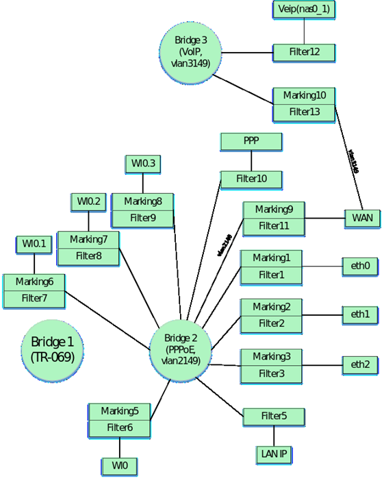
After applying all the above parameters, we get this logical ONT configuration:
Note: the numbers above the interfaces indicate the FilterInterface value for each interface.
Next we create a Bridge 3 for VoIP service in vlan 3149.
"InternetGatewayDevice.Layer2Bridging.Bridge.3.BridgeEnable" "1"
"InternetGatewayDevice.Layer2Bridging.Bridge.3.BridgeName" "VoIP"
"InternetGatewayDevice.Layer2Bridging.Bridge.3.VLANID" "3149"
Bind the WAN interface to Bridge 3: In addition to binding the WAN interface to the bridge it is also necessary to bind the virtual veip interface for VoIP service. Binding of the veip interface is performed according to the same rules as binding of the virtual PPP interface, which was discussed earlier. Thus, the following parameters will need to be added to the profile to bind WAN and veip interfaces to Bridge 3:
"InternetGatewayDevice.Layer2Bridging.Filter.13.FilterEnable" "1"
"InternetGatewayDevice.Layer2Bridging.Filter.13.FilterInterface" "5"
"InternetGatewayDevice.Layer2Bridging.Filter.13.FilterBridgeReference" "2"

"InternetGatewayDevice.Layer2Bridging.Filter.12.FilterEnable" "1"
"InternetGatewayDevice.Layer2Bridging.Filter.12.FilterInterface" "13"
"InternetGatewayDevice.Layer2Bridging.Filter.12.FilterBridgeReference" "2"

"InternetGatewayDevice.Layer2Bridging.Marking.10.MarkingEnable" "1"
"InternetGatewayDevice.Layer2Bridging.Marking.10.MarkingInterface" "5"
"InternetGatewayDevice.Layer2Bridging.Marking.10.MarkingBridgeReference" "2"
"InternetGatewayDevice.Layer2Bridging.Marking.10.VLANIDMark" "3149"
"InternetGatewayDevice.Layer2Bridging.Marking.10.VLANIDUntag" "0"
Next, you need to configure the WAN interface for the VoIP service. Configuring the interface is done using the following parameters:
"InternetGatewayDevice.WANDevice.1.WANConnectionDevice.1.WANIPConnection.2.Enable" "1" – this parameter enables/disables WAN veip interface. Value "1" – enable, "0" – disable
"InternetGatewayDevice.WANDevice.1.WANConnectionDevice.1.WANIPConnection.2.ConnectionType" "IP_Routed" – this parameter specifies interface type. The "IP_Routed" value specifies the router interface.
"InternetGatewayDevice.WANDevice.1.WANConnectionDevice.1.WANIPConnection.2.AddressingType" "DHCP" – this parameter activates the address obtaining for the WAN interface for VoIP via DHCP.
"InternetGatewayDevice.WANDevice.1.WANConnectionDevice.1.WANPPPConnection.1.NATEnabled" "0" – enabling NAT on the veip interface for translation of addresses from the local network. "1" - NAT enabled, "0" - NAT disabled.
"InternetGatewayDevice.WANDevice.1.WANConnectionDevice.1.WANIPConnection.2.X_RTK_ServiceType" "4" – by using this parameter the type of service on the interface is specified (all variants of values of this parameter were given above when configuring PPP)
"InternetGatewayDevice.WANDevice.1.WANConnectionDevice.1.WANIPConnection.2.Name" "VoIP" – this parameter specifies the name "VoIP" for the veip interface. Any name can be set.
Note that WANIPConnection value number 2 is used for the WAN interface. The first interface is dedicated to using TR-069. Therefore a parameter must be added to the profile before the telephony WAN interface description, which will include the first WAN interface for TR-069:
"InternetGatewayDevice.WANDevice.1.WANConnectionDevice.1.WANIPConnection.1.Enable" "1"
After applying the parameters listed above, we obtain the following logical structure of ONT:
With the ACS, you can configure settings for the ONT VoIP client. The main parameters and their description are given below:
"InternetGatewayDevice.Services.VoiceService.1.VoiceProfile.1.SIP.UserAgentDomain" "192.168.101.2" – setting this parameter is mandatory, without it VoIP client does not work, the value of this parameter must be the same as ProxyServer or RegistarServer.
"InternetGatewayDevice.Services.VoiceService.1.VoiceProfile.1.SIP.ProxyServer" "192.168.101.2" – this parameter sets the registration servers. Either an IP address or a domain name can be used as the value (e.g. ngn-sip.sinor.ru).
"InternetGatewayDevice.Services.VoiceService.1.VoiceProfile.1.SIP.UserAgentPort" "5060" – this parameter defines the port in which the VoIP client ONT is running, the value 5060 is standard
"InternetGatewayDevice.Services.VoiceService.1.VoiceProfile.1.SIP.RegistrarServer" "192.168.101.2" – parameter to set the registration server. Either an IP address or a domain name can be used as the value (e.g. ngn-sip.sinor.ru).
"InternetGatewayDevice.Services.VoiceService.1.VoiceProfile.1.SIP.RegistrarServerPort" "5060" – specifying the port where the SIP server is running, the value 5060 is standard
"InternetGatewayDevice.Services.VoiceService.1.VoiceProfile.1.SIP.OutboundProxy" "192.168.101.2" – this parameter sets the OutboundProxy address. Either an IP address or a domain name can be used as the value (e.g. ngn-sip.sinor.ru).
"InternetGatewayDevice.Services.VoiceService.1.VoiceProfile.1.SIP.OutboundProxyPort" "5060" – this parameter defines the port for Outbound Proxy, 5060 – default value
"InternetGatewayDevice.Services.VoiceService.1.VoiceProfile.1.SIP.RegisterExpires" "600" – this parameter specifies the time during which the SIP client registration on the server expires.
"InternetGatewayDevice.Services.VoiceService.1.VoiceProfile.1.SIP.RegistrationPeriod" "600" – acs parameter that specifies the period of time after which VoIP client will send a request for re-registration.
"InternetGatewayDevice.Services.VoiceService.1.VoiceProfile.1.DigitMap" "x.T" – parameter to configure the dial plan.
"InternetGatewayDevice.Services.VoiceService.1.VoiceProfile.1.DigitMapEnable" "1" – parameter to enable/disable the dial plan (1 - enabled, 0 - disabled).
"InternetGatewayDevice.Services.VoiceService.1.VoiceProfile.1.Line.1.Enable" "Enabled" – enable first phone line
"InternetGatewayDevice.Services.VoiceService.1.VoiceProfile.1.Line.1.SIP.AuthUserName" "420012" – acs parameter that specifies sip client name
"InternetGatewayDevice.Services.VoiceService.1.VoiceProfile.1.Line.1.SIP.AuthPassword" "420012" – acs parameter that specifies sip client password
"InternetGatewayDevice.Services.VoiceService.1.VoiceProfile.1.Line.1.DirectoryNumber" "420012" – this parameter specifies sip client phone number
"InternetGatewayDevice.Services.VoiceService.1.VoiceProfile.1.Line.1.CallingFeatures.CallerIDName" "420012" – this parameter specifies CallerID of the client.
"InternetGatewayDevice.Services.VoiceService.1.VoiceProfile.1.Line.1.SIP.URI" "420012" – SIP URI of the sip client. By default, it should be the same as DirectoryNumber.
Similar parameters are used to configure the second line. Examples of parameters without a description of their values are given below:
"InternetGatewayDevice.Services.VoiceService.1.VoiceProfile.2.SIP.UserAgentDomain" "192.168.101.2"
"InternetGatewayDevice.Services.VoiceService.1.VoiceProfile.2.SIP.ProxyServer" "192.168.101.2"
"InternetGatewayDevice.Services.VoiceService.1.VoiceProfile.2.SIP.UserAgentPort" "5060"
"InternetGatewayDevice.Services.VoiceService.1.VoiceProfile.2.SIP.RegistrarServer" "192.168.101.2"
"InternetGatewayDevice.Services.VoiceService.1.VoiceProfile.2.SIP.RegistrarServerPort" "5060"
"InternetGatewayDevice.Services.VoiceService.1.VoiceProfile.2.SIP.OutboundProxy" "192.168.101.2"
"InternetGatewayDevice.Services.VoiceService.1.VoiceProfile.2.SIP.OutboundProxyPort" "5060"
"InternetGatewayDevice.Services.VoiceService.1.VoiceProfile.2.SIP.RegisterExpires" "600"
"InternetGatewayDevice.Services.VoiceService.1.VoiceProfile.2.SIP.RegistrationPeriod" "600"

"InternetGatewayDevice.Services.VoiceService.1.VoiceProfile.2.DigitMap" "x.T"
"InternetGatewayDevice.Services.VoiceService.1.VoiceProfile.2.DigitMapEnable" "1"

"InternetGatewayDevice.Services.VoiceService.1.VoiceProfile.2.Line.1.Enable" "Enabled"
"InternetGatewayDevice.Services.VoiceService.1.VoiceProfile.2.Line.1.SIP.AuthUserName" "420011"
"InternetGatewayDevice.Services.VoiceService.1.VoiceProfile.2.Line.1.SIP.AuthPassword" "420011"
"InternetGatewayDevice.Services.VoiceService.1.VoiceProfile.2.Line.1.DirectoryNumber" "420011"
"InternetGatewayDevice.Services.VoiceService.1.VoiceProfile.2.Line.1.CallingFeatures.CallerIDName" "420011"
"InternetGatewayDevice.Services.VoiceService.1.VoiceProfile.2.Line.1.SIP.URI" "420011"
Then form Bridge 4 in vlan 30, where IGMP Proxy will work and bind WAN interface to it.
"InternetGatewayDevice.Layer2Bridging.Bridge.4.BridgeEnable" "1"
"InternetGatewayDevice.Layer2Bridging.Bridge.4.BridgeName" "proxy"
"InternetGatewayDevice.Layer2Bridging.Bridge.4.VLANID" "30"

"InternetGatewayDevice.Layer2Bridging.Filter.15.FilterEnable" "1"
"InternetGatewayDevice.Layer2Bridging.Filter.15.FilterInterface" "5"
"InternetGatewayDevice.Layer2Bridging.Filter.15.FilterBridgeReference" "3"

"InternetGatewayDevice.Layer2Bridging.Marking.11.MarkingEnable" "1"
"InternetGatewayDevice.Layer2Bridging.Marking.11.MarkingInterface" "5"
"InternetGatewayDevice.Layer2Bridging.Marking.11.MarkingBridgeReference" "3"
"InternetGatewayDevice.Layer2Bridging.Marking.11.VLANIDMark" "30"
"InternetGatewayDevice.Layer2Bridging.Marking.11.VLANIDUntag" "0"
Create a virtual veip interface for IGMP-Proxy and bind it to Bridge 4, considering that interfaces are not bound by default only by filters.
"InternetGatewayDevice.Layer2Bridging.Filter.14.FilterEnable" "1"
"InternetGatewayDevice.Layer2Bridging.Filter.14.FilterInterface" "14"
"InternetGatewayDevice.Layer2Bridging.Filter.14.FilterBridgeReference" "3"
The FilterInterface value for IGMP Proxy is 14 because the previous VoIP interface had a value of 13.
Configure the IGMP Proxy interface with the following ACS parameters:
"InternetGatewayDevice.WANDevice.1.WANConnectionDevice.1.WANIPConnection.3.Enable" "1" – enables WANIP interface
"InternetGatewayDevice.WANDevice.1.WANConnectionDevice.1.WANIPConnection.1.ConnectionType" "IP_Routed" – this parameter specifies router interface type
"InternetGatewayDevice.WANDevice.1.WANConnectionDevice.1.WANIPConnection.1.AddressingType" "Static" – this parameter specifies that the address for IGMP Proxy is set statically. "Static" value
"InternetGatewayDevice.WANDevice.1.WANConnectionDevice.1.WANIPConnection.1.ExternalIPAddress" "192.168.25.21" – this parameter sets a static IP address for IGMP-Proxy
"InternetGatewayDevice.WANDevice.1.WANConnectionDevice.1.WANIPConnection.1.SubnetMask" "255.255.255.0" – sets the subnet mask for IGMP Proxy
"InternetGatewayDevice.WANDevice.1.WANConnectionDevice.1.WANIPConnection.1.DefaultGateway" "192.168.25.1" – parameter specifies the default gateway
"InternetGatewayDevice.WANDevice.1.WANConnectionDevice.1.WANPPPConnection.1.NATEnabled" "0" – enabling NAT on the veip interface for translation of addresses from the local network. "1" - NAT enabled, "0" - NAT disabled.
"InternetGatewayDevice.WANDevice.1.WANConnectionDevice.1.WANIPConnection.3.X_RTK_ServiceType" "0" – this parameter defines the type of service on the interface.
"InternetGatewayDevice.WANDevice.1.WANConnectionDevice.1.WANIPConnection.3.X_RTK_IGMPProxy" "1" – this parameter enables/disables the IGMP-proxy function for intercepting and forwarding IGMP messages.
The static address 192.168.25.21 for IGMP is given as an example. When writing a profile, you can replace this address with any other address.
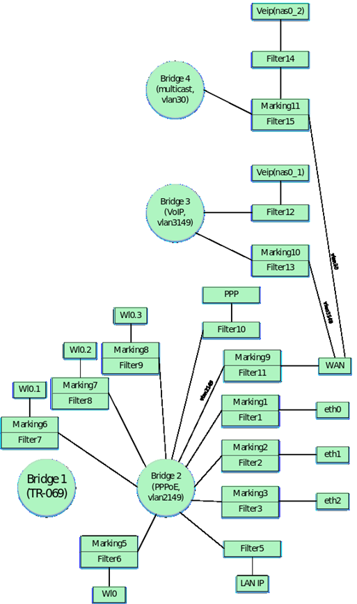
After adding Bridge 4 and IGMP Proxy, the ONT configuration will look like this.
Next form Bridge 5 for STB service, which will work in vlan 2349:
"InternetGatewayDevice.Layer2Bridging.Bridge.5.BridgeEnable" "1"
"InternetGatewayDevice.Layer2Bridging.Bridge.5.BridgeName" "STB"
"InternetGatewayDevice.Layer2Bridging.Bridge.5.VLANID" "2349"
ONT should be configured so that IP-TV media player receives addresses from LAN port 4 to vlan 2349. Previously in the profile we associated the first 3 Ethernet interfaces of ONT with Bridge 1. Now it is necessary to bind the eth.3 interface to Bridge 5 similarly. To bind the eth3 interface use the default numbering for Marking, Filter and FilterInterface:
"InternetGatewayDevice.Layer2Bridging.Filter.4.FilterEnable" "1"
"InternetGatewayDevice.Layer2Bridging.Filter.4.FilterInterface" "4"
"InternetGatewayDevice.Layer2Bridging.Filter.4.FilterBridgeReference" "4"

"InternetGatewayDevice.Layer2Bridging.Marking.4.MarkingEnable" "1"
"InternetGatewayDevice.Layer2Bridging.Marking.4.MarkingInterface" "4"
"InternetGatewayDevice.Layer2Bridging.Marking.4.MarkingBridgeReference" "4"
Bind the WAN interface to Bridge 5
"InternetGatewayDevice.Layer2Bridging.Marking.12.MarkingEnable" "1"
"InternetGatewayDevice.Layer2Bridging.Marking.12.MarkingInterface" "5"
"InternetGatewayDevice.Layer2Bridging.Marking.12.MarkingBridgeReference" "4"
"InternetGatewayDevice.Layer2Bridging.Marking.12.VLANIDMark" "2349"
"InternetGatewayDevice.Layer2Bridging.Marking.12.VLANIDUntag" "0"

"InternetGatewayDevice.Layer2Bridging.Filter.16.FilterEnable" "1"
"InternetGatewayDevice.Layer2Bridging.Filter.16.FilterInterface" "5"
"InternetGatewayDevice.Layer2Bridging.Filter.16.FilterBridgeReference" "4"
Since the traffic through Bridge 4 will pass transparently, only with vlan 2349 unchecked, no additional ACS parameters other than Marking and Filter are required. That is, if it is necessary to provide a subscriber with some service by a bridge, it is enough to make a binding of a necessary port to bridge and binding of WAN interface to this bridge. Note that if the interface is configured as bridge, the WAN interface is not configured. Thus, there is no WANIPConnection configuration for this interface in the profile.
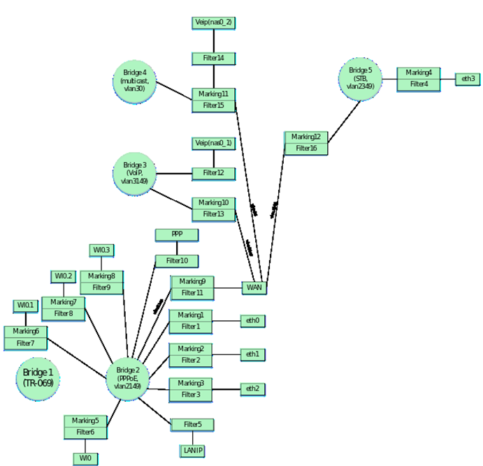
Finally, on an ONT that is fully configured for this profile, the following logical architecture will be used:
Basic settings to configure ONT via ACS
Now consider the basic parameters for ACS, which are most often used in operation when setting up ONT.
Changing password on ONT
The parameter to change the password from the admin user:
"InternetGatewayDevice.LANConfigSecurity.ConfigPassword" "new_password_admin"
The parameter to change the password from the user user:
"InternetGatewayDevice.LANConfigSecurity.ConfigPassword" "new_password_user"
Parameters for configuring Wi-Fi
Enable/disable network:
Network name change:
For 2.4 ГГц: "InternetGatewayDevice.LANDevice.1.WLANConfiguration.1.SSID" "new_ssid"
For 5 ГГц: "InternetGatewayDevice.LANDevice.1.WLANConfiguration.5.SSID" "new_ssid"
Password changing:
For 2.4 ГГц: "InternetGatewayDevice.LANDevice.1.WLANConfiguration.#1.KeyPassphrase" "new_password"
For 5 ГГц: "InternetGatewayDevice.LANDevice.1.WLANConfiguration.#5.KeyPassphrase" "new_password"
Configuring remote access to ONT
The list of remote access rules should start with the default rules for br0. After configuring the default rules for br0, rules are configured for access to the nas0_0 interface, then for all other interfaces. When adding rules, you should follow their numbering.
An example of configuring rules for remote access to ONT to the local br0 interface via ICMP and HTTP and to the nas0_0 interface via TELNET:
"InternetGatewayDevice.UserInterface.RemoteAccess.1.Enable" "1" – enable rule to add;
"InternetGatewayDevice.UserInterface.RemoteAccess.1.Interface" "br0" – specifies the interface to which access is required;
"InternetGatewayDevice.UserInterface.RemoteAccess.1.IP" "0.0.0.0" – configures the source IP address;
"InternetGatewayDevice.UserInterface.RemoteAccess.1.Mask" "0.0.0.0" – specifies the subnet mask;
"InternetGatewayDevice.UserInterface.RemoteAccess.1.Protocol" "ICMP" – this parameter specifies the protocol type (you can configure the TELNET and HTTP protocols in addition to ICMP).
"InternetGatewayDevice.UserInterface.RemoteAccess.2.Enable" "1"
"InternetGatewayDevice.UserInterface.RemoteAccess.2.Interface" "br0"
"InternetGatewayDevice.UserInterface.RemoteAccess.2.IP" "0.0.0.0"
"InternetGatewayDevice.UserInterface.RemoteAccess.2.Mask" "0.0.0.0"
"InternetGatewayDevice.UserInterface.RemoteAccess.2.Port" "80" – this parameter specifies the destination port number (port 80 is specified for WEB access, port 23 for telnet access. If ICMP protocol is used, the port number should not be configured)
"InternetGatewayDevice.UserInterface.RemoteAccess.2.Protocol" "HTTP"

"InternetGatewayDevice.UserInterface.RemoteAccess.3.Enable" "1"
"InternetGatewayDevice.UserInterface.RemoteAccess.3.Interface" "nas0_0"
"InternetGatewayDevice.UserInterface.RemoteAccess.3.IP" "0.0.0.0"
"InternetGatewayDevice.UserInterface.RemoteAccess.3.Mask" "0.0.0.0"
"InternetGatewayDevice.UserInterface.RemoteAccess.3.Port" "23"
"InternetGatewayDevice.UserInterface.RemoteAccess.3.Protocol" "TELNET"
Port forwarding configuration
"InternetGatewayDevice.WANDevice.1.WANConnectionDevice.1.WANIPConnection.2.PortMapping.1.ExternalPort" "100" – starting external port
"InternetGatewayDevice.WANDevice.1.WANConnectionDevice.1.WANIPConnection.2.PortMapping.1.InternalClient" "192.168.1.100" – the local IP address to which the port is forwarded
"InternetGatewayDevice.WANDevice.1.WANConnectionDevice.1.WANIPConnection.2.PortMapping.1.InternalPort" "100" – staring internal port
"InternetGatewayDevice.WANDevice.1.WANConnectionDevice.1.WANIPConnection.2.PortMapping.1.PortMappingDescription" "100" – rule name
"InternetGatewayDevice.WANDevice.1.WANConnectionDevice.1.WANIPConnection.2.PortMapping.1.PortMappingEnabled" "1" – port forwarding permition
"InternetGatewayDevice.WANDevice.1.WANConnectionDevice.1.WANIPConnection.2.PortMapping.1.PortMappingProtocol" "TCP" – protocol type
"InternetGatewayDevice.WANDevice.1.WANConnectionDevice.1.WANIPConnection.2.PortMapping.1.RemoteHost" "0.0.0.0"
"InternetGatewayDevice.WANDevice.1.WANConnectionDevice.1.WANIPConnection.2.PortMapping.1.X_ELTEX_RU_ExternalPortEnd" "100" – ending external port
"InternetGatewayDevice.WANDevice.1.WANConnectionDevice.1.WANIPConnection.2.PortMapping.1.X_ELTEX_RU_InternalPortEnd" "100" – ending internal port
DMZ configuration
"InternetGatewayDevice.X_ELTEX_RU_SecDmzHostCfg.IPAddress" "192.168.1.15"
NTP configuration
"InternetGatewayDevice.Time.Enable" "1" – parameter to enable SNTP synchronization
"InternetGatewayDevice.Time.LocalTimeZone" "+06:00" – parameter to configure the timezone
"InternetGatewayDevice.Time.NTPServer1" "pool.ntp.org" – parameter specifies the server