Firmware version 1.5.0 |
EVI Platform is designed to organize a unified system for management, configuration and monitoring of devices (controllers, cameras and sensors).
Using this system with a web GUI makes it possible to:
The EVI platform consists of the following components:
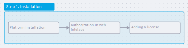
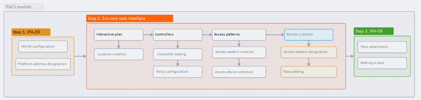
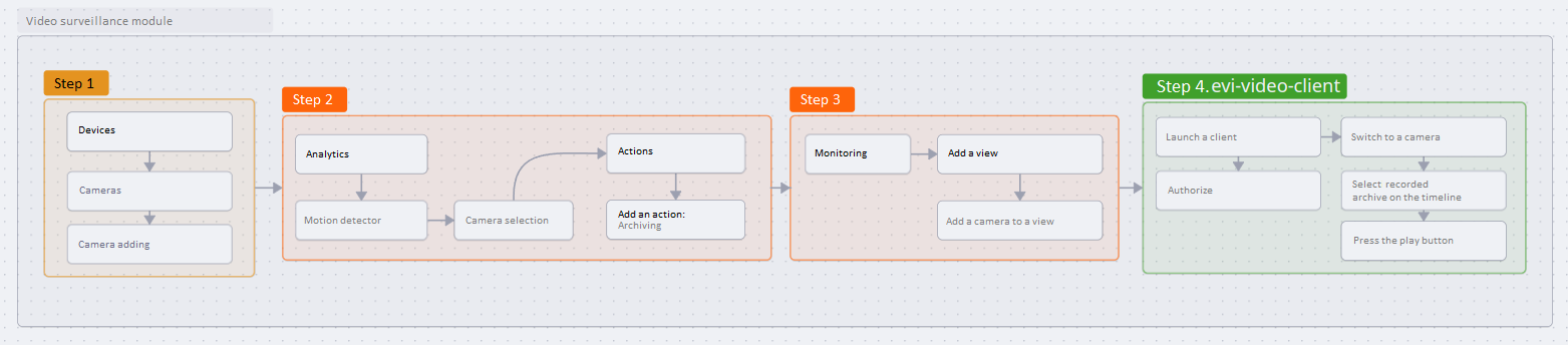
System requirements are described in the Personnel and equipment requirements document.
Installation porcess is described in the EVI Platform installation document.
The device can be added manually or automatically.
For more information about automatic mode, see the Connecting the IPA-ER controller section.
In this example, the controller is added manually. |
Enter the web interface of the IPA-ER-020 controller. You can learn more about the device using IPA-ER-020 PACS controller documentation.
Connect to the web interface of the device using IP address 192.168.1.10 with HTTP protocol. If the IP address is assigned by a DHCP server, it is necessary to verify the address directly at the server. The IP address of the computer must be in the same subnet as the device. For example, by default it is 192.168.1.11/24. |
On the authorization page, enter the following data in the Login and Password fields:
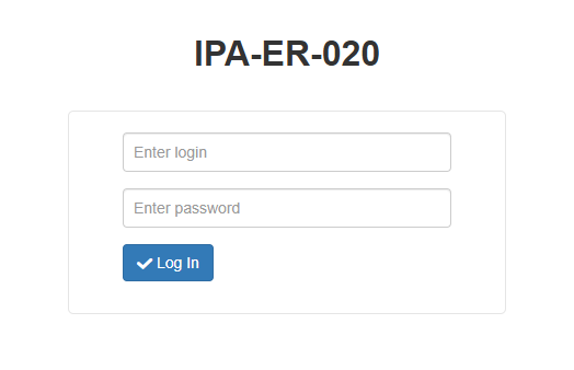
Click the Log in button.
Enter Network Settings section and select the EVI Platform tab.
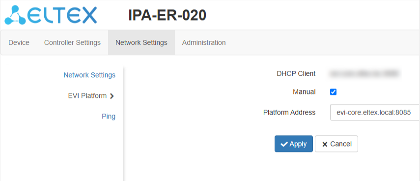
If the address does not match the default (evi-core.eltex.local:8085) and cannot be obtained from DHCP in option (43), then it is necessary to check the Manual option.
Enter the evi-core server address in the Platform Address field:
<evi-core IP address>:8085 |
Click the Apply button.
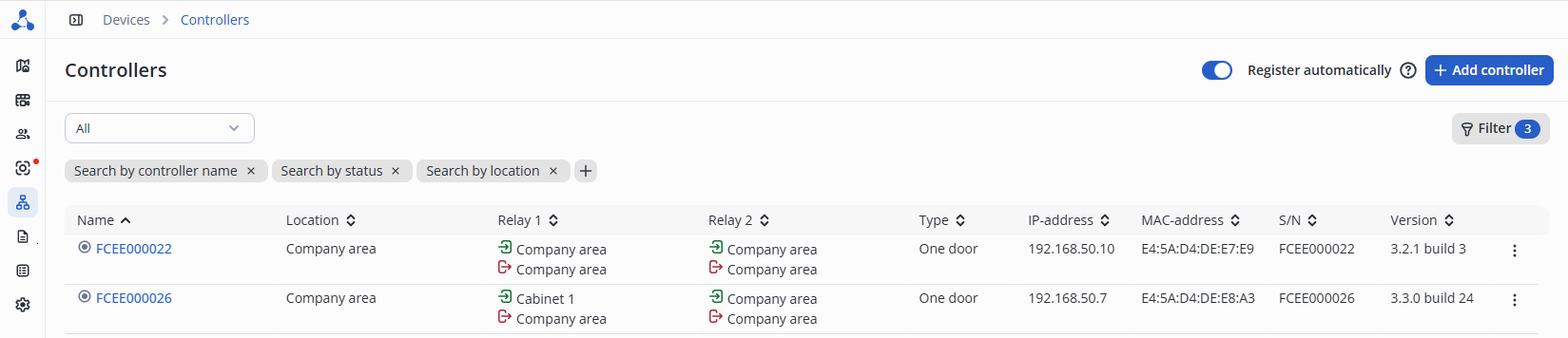
The controller will then appear in the Controllers table under Devices section on the EVI Platform as an unauthorized controller.
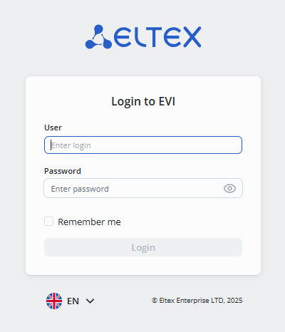
Type https://IP address of the server or https://host name in the browser address bar.
In the authorization form, enter:
Detailed settings are described in the PACS module documentation.
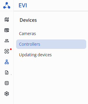
Enter the Controllers page in the Devices section of the web interface.
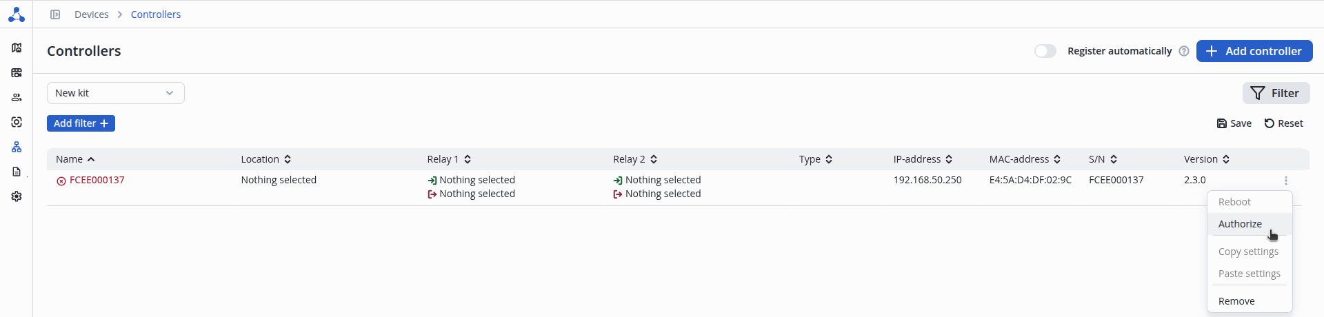
Click on the three dots on the right side of the line, select Authorize, and click the Authorize button.
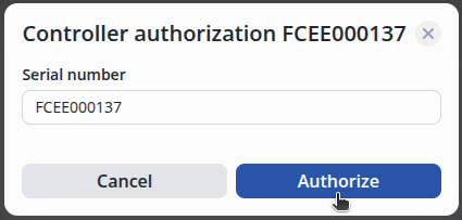
The serial number is automatically inserted, click on the Authorize button on the bottom right.
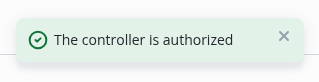
After successful addition, a message will be displayed in the bottom center of the screen indicating that the addition was successful.
The example below shows that one door is connected with a door open sensor, one pass reader and a door open button.
Switch to diagram 2 and connect the pass reader, door open sensor, door open button, door magnet to the IPA-ER controller.
| Examples of connection diagrams for the IPA-ER-020 controller are provided in the PACS module document under the Controller Connection Diagrams section. |
Locations are necessary for tracking employees' movement history and for conveniently managing access to the locations. |
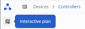
Select Interactive plan from the side menu.
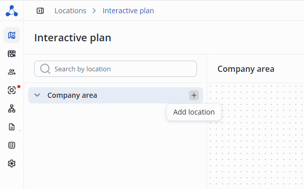
Click the + button under Company area, then Add location.
.
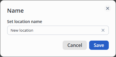
Enter the name of the new location and click Save.
For a new location named New location, click the three dots on the right side and select Rename.
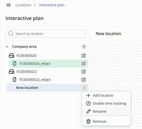
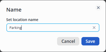
Enter the name of the new location, for example, Parking, and save by clicking on the check mark or pressing the Enter key.
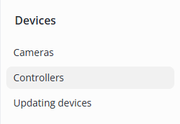
Select Controllers from the side menu in the Devices section.
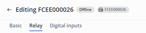
Click on the name of the controller.

Switch to the Relay tab.
Select Control Type – One Door in the Settings section.
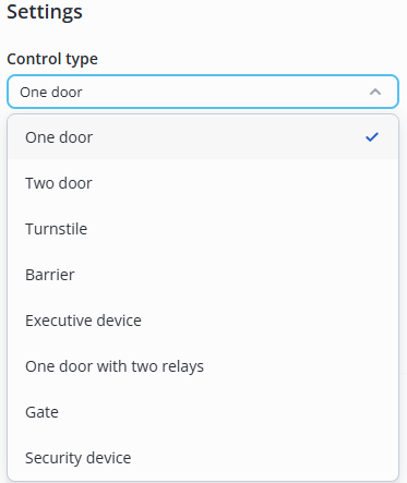
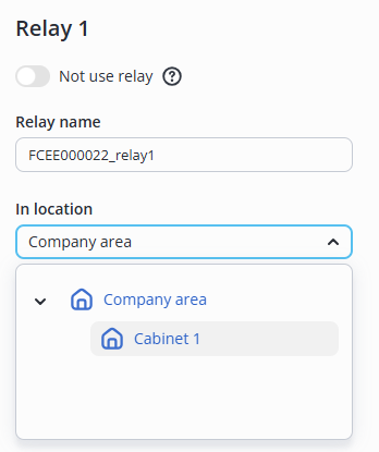
Specify the name of the relay – Cabinet 1.
For Relay 1, select the following:
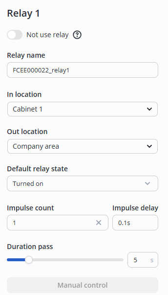
Switch to the Digital inputs tab.
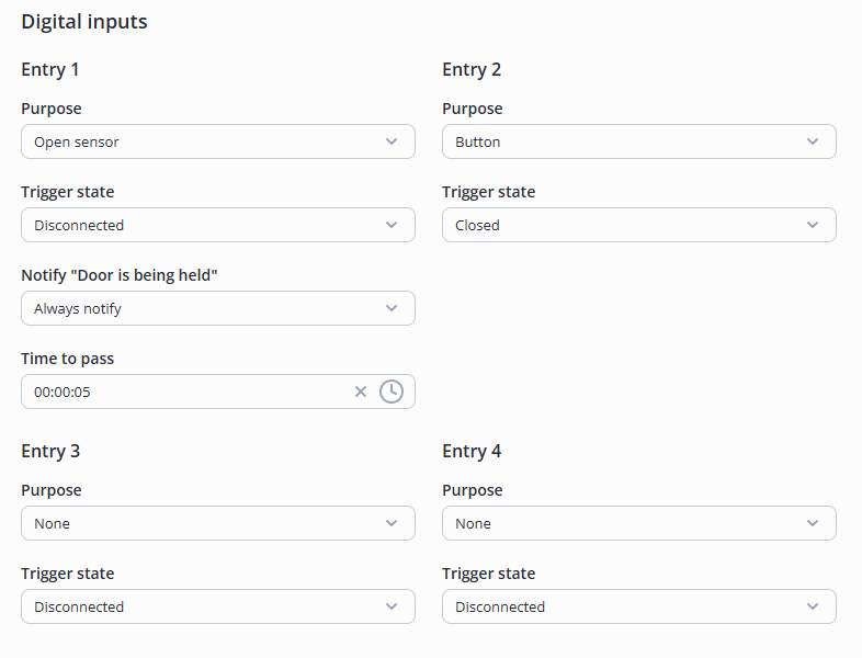
1 and 2 digital inputs are connected to relay 1. |
For 1 digital input, select the following:
For 2 digital input, select the following:
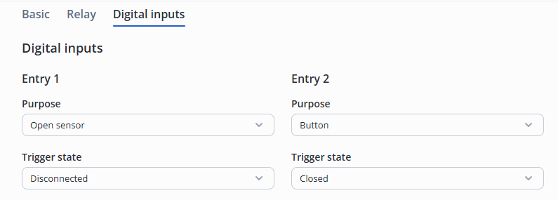
Click the Save button in the lower right corner.
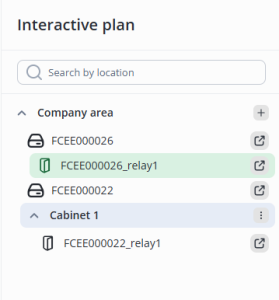
Then, relay 1, which controls the door, will be displayed on the Interactive plan page in Cabinet 1.
To enable access for an employee to the Cabinet 1, it is necessary to create an access pattern.
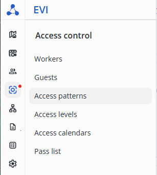
Enter the Access control section, and select the Access patterns item in the menu.
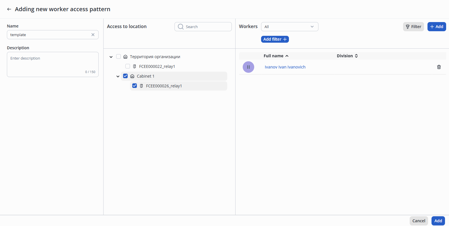
Click the Add access button, select the Worker pattern option.

Fill in the fields:
Mark in the middle column (Access to location) the access objects that can be passed through in this access pattern.
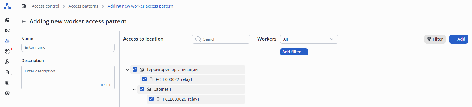
Click the Add button in the far right column to select from the list of workers who are permitted to have access to the locations within this pattern.

In the appeared list select workers and click the Add button.
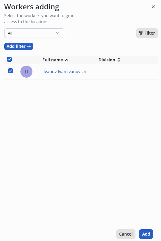
After adding workers, click the Add button in the lower right corner.
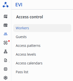
Enter the Workers page in the Access control section.
Click the +Add worker button.

Fill in the full name. The rest of the fields are optional.
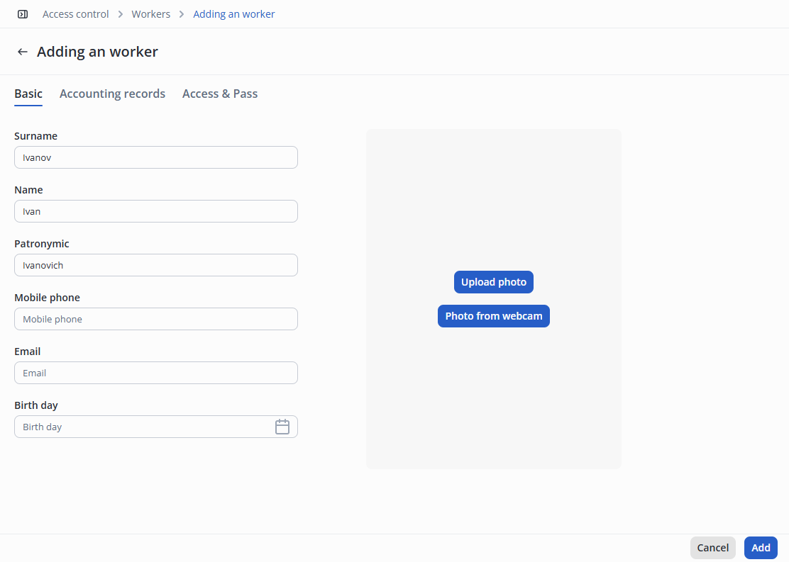
Click the Add button in the lower right corner of the screen.
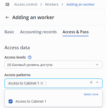
Switch to the Access & Pass tab.
Click the Access Patterns, select the previously created Access to Cabinet 1.
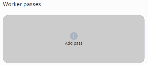
Click the Add pass button in the Worker passes section.
Scan the pass at the USB reader or enter the code from the pass. Example: 11164609.
Zeros after entry will be discarded. It is not necessary to fill them in. |
For the example below, a pass number with zeros was used.
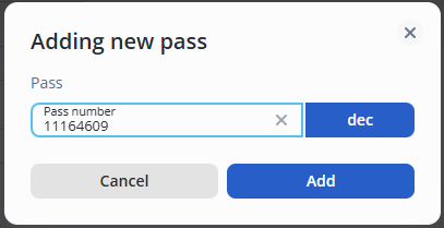
Click the Add button.
Click the Save button in the lower right corner to save the steps.
Try to make a pass through the door. To do this, perform the following steps:
In the Journals section, the worker`s pass will be displayed on the Passages page.
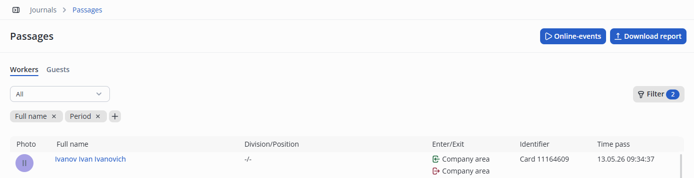
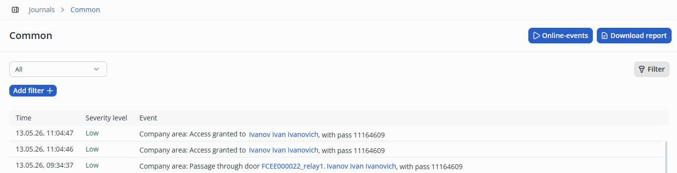
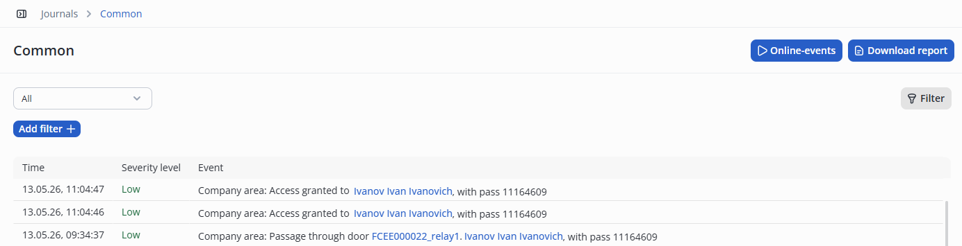
The Common page in the Journals section will display more detailed information about the worker passing through the door.
Detailed settings and recommendations for the cameras are described in the Video surveillance module document.
In the Devices section, switch to the Cameras page.
Click Add camera and select Manual addition from the submenu that opens.

On the Manual camera adding page, fill in the following fields:
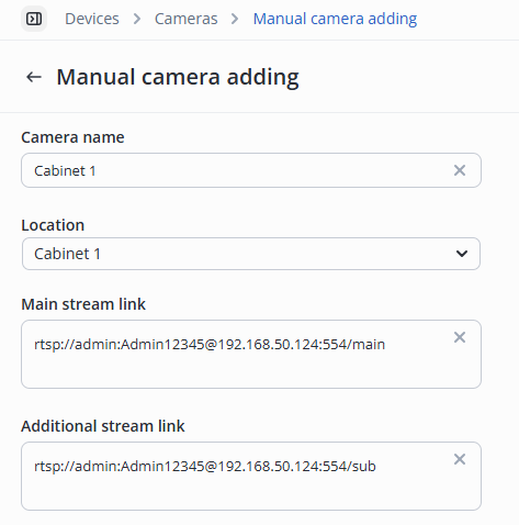
Click the Add camera manually button in the lower right corner.
Detailed settings are described in the Adding a camera document.
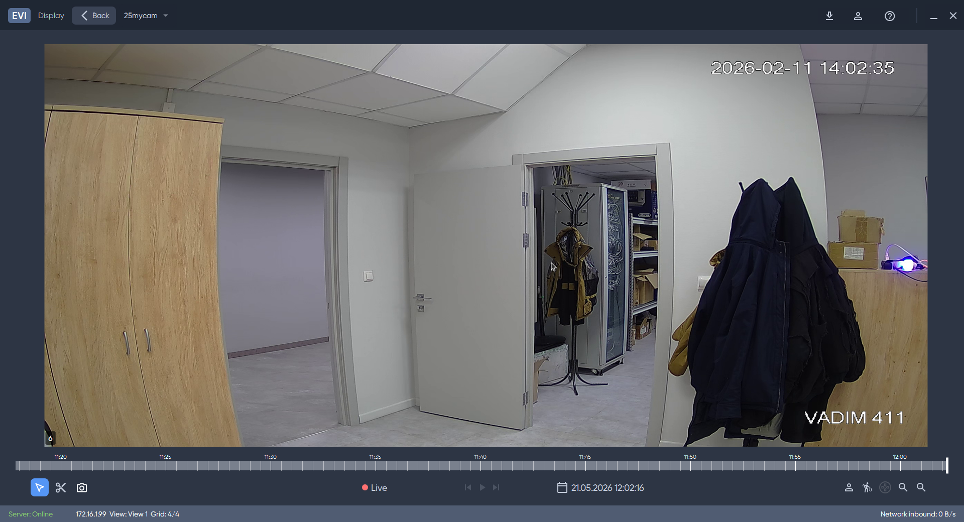
When editing camera functionality, a player is available in the browser to view LIVE stream and archive.
A more detailed description of the player can be found in the EVI Platform in a browser section.
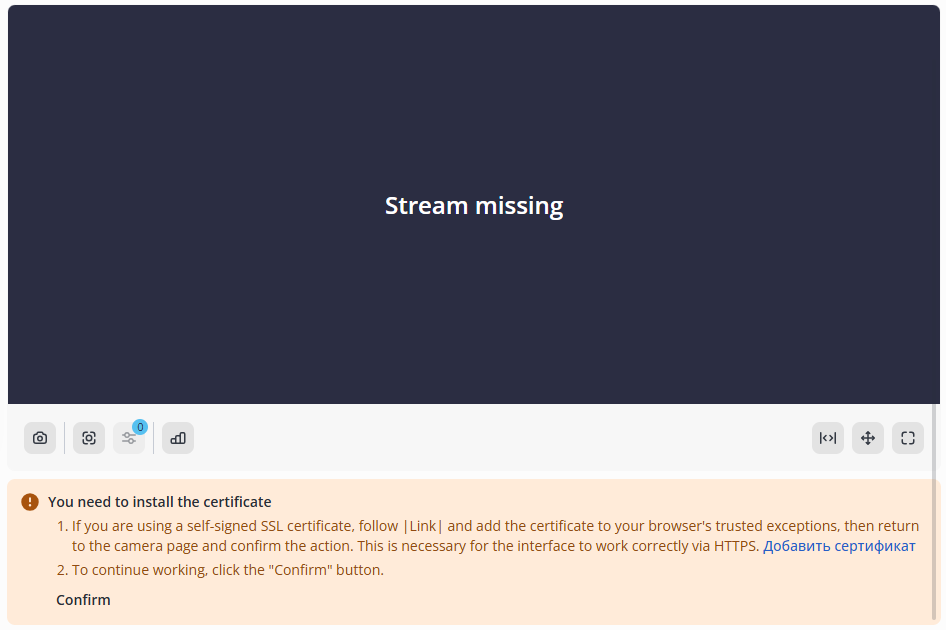
When using a self-signed certificate, it is necessary to confirm its exception in the player to view the video stream from the camera.
Detailed configuration is described in Recommendations for cameras with motion detector and Adding a camera sections.
Switch to the Video analytics page.
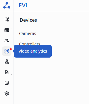
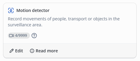
Click Edit next to the Motion detector model.
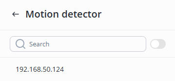
Select the desired camera from the list.
This section is used to configure the server-side motion detector.
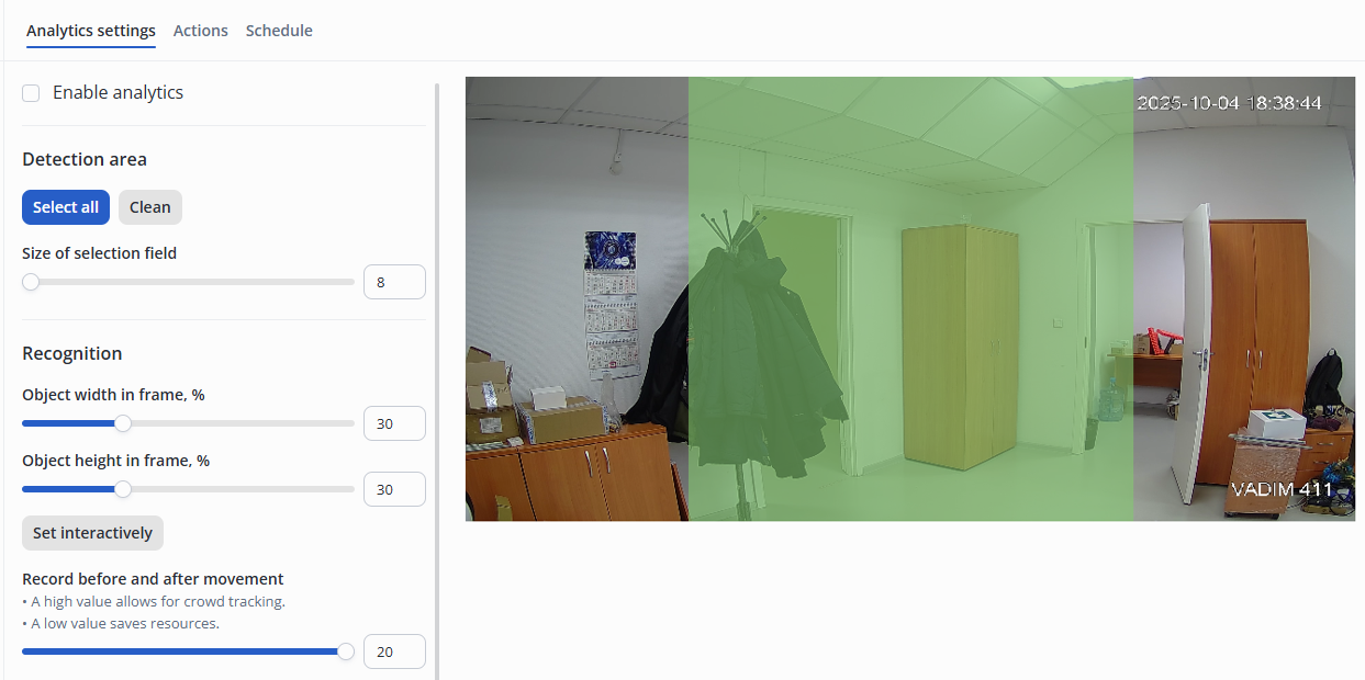
Configuration parameters:
To configure the motion detector grid, select camera areas by left-clicking on the camera image.
Use the right mouse button to erase an area.
Data from the camera is recorded to the server in the section specified in the evi-archive.conf configuration file, without using the SD card in the camera.
Cameras with "By movement" archive type will automatically switch to permanent archive recording type in case of problems with evi-analyzer service availability. When the problems with evi-analyzer service are eliminated, cameras with "By movement" archive type will automatically switch from permanent to "By movement" recording. |
Switch to the Actions tab and click Add.

Next, select the type of action – Record to archive, set the desired gap time for turning off the recording after movement.
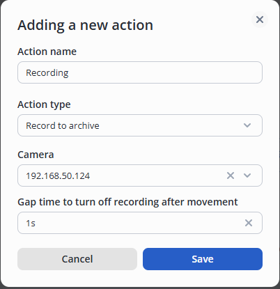
To save the settings, click the Save button at the bottom right of the screen.
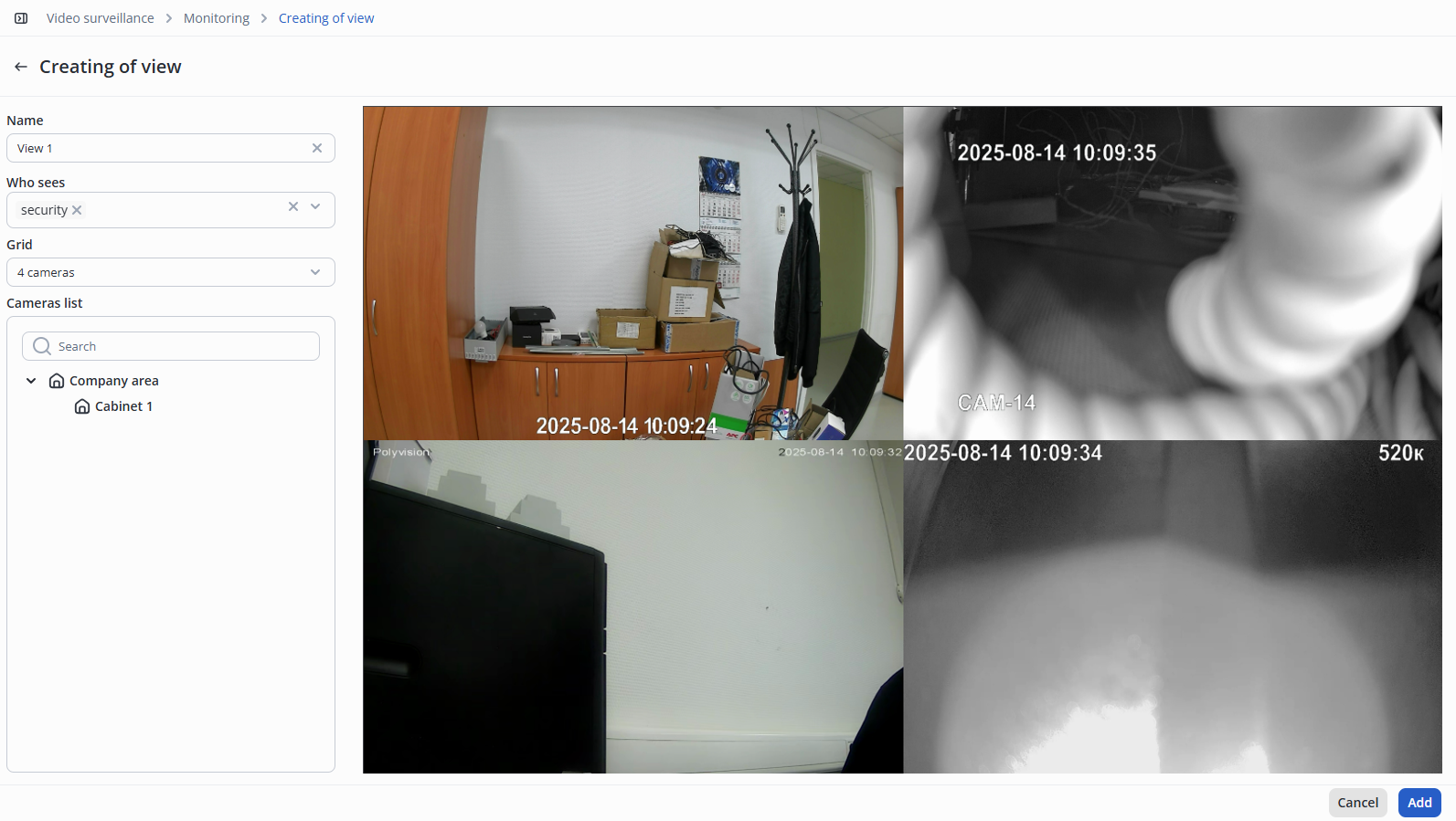
To create a view, switch to the Video surveillance section, select the Monitoring tab, and click the +Add view button.

In the Name field, enter a name for the view.
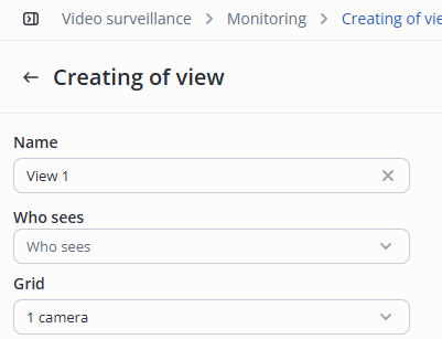
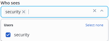
The drop-down list Who sees displays all users with the Security role. Select the users who will be able to have an access to the view. Roles are described in the System users section.
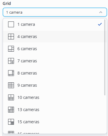
In the Grid drop-down list, select the number and layout of cameras that will be displayed in evi-video-client.
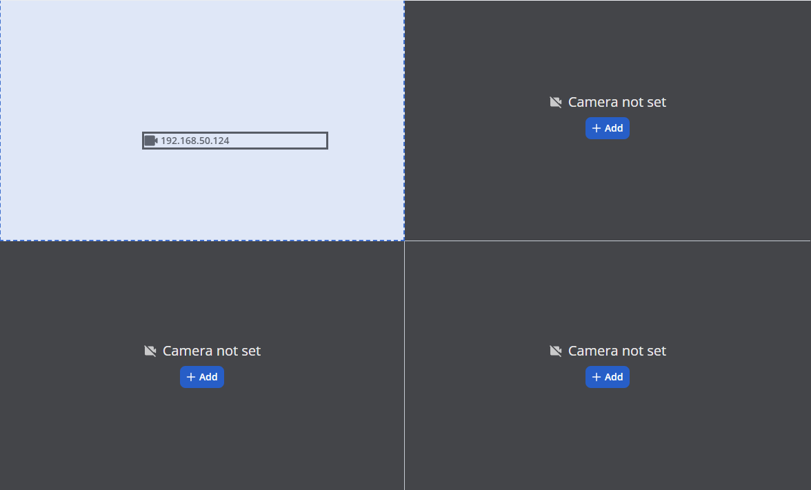
After making a selection, a camera layout grid will appear on the right side of the screen.
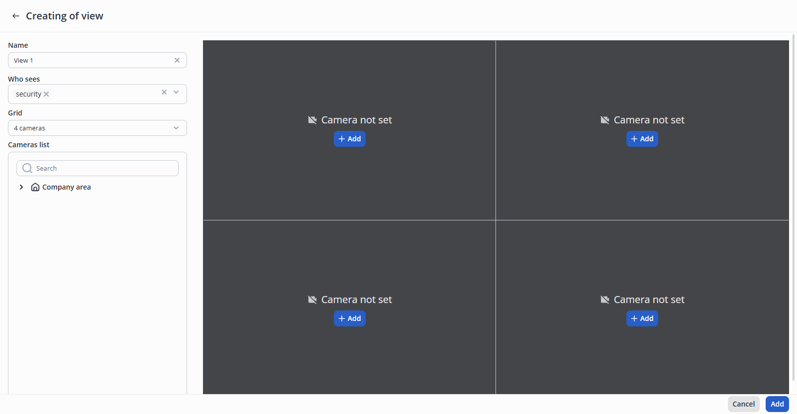
There are two ways to add a camera to a view.
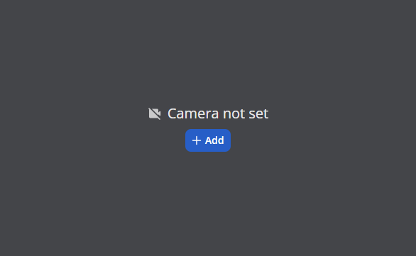
On the grid, click the Add button.
In the pop-up window that opens, open the drop-down list.
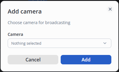
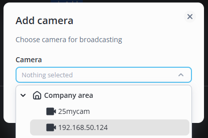
From the drop-down list, select the camera you want to add to the video view, then click the Add button.
Find the desired camera in the camera list.
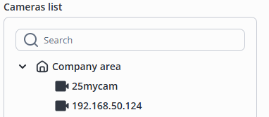
Hover the mouse cursor over it and hold down the left mouse button. Without releasing the left mouse button, drag the camera to the desired cell in the view grid. Release the left mouse button after selecting the view cell.
To create a view with the selected cameras, click the Add button.
Launch the application and wait for the window to appear where you can enter your username and password.
The user is created immediately after installing the EVI Platform. Before logging in, use the administrator account to add a Video view with cameras for this user. User – security; Password – password. |
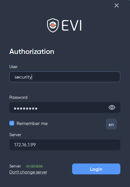
Click the Login button.
To view the recorded videos, click the video image from the camera with the left mouse button.
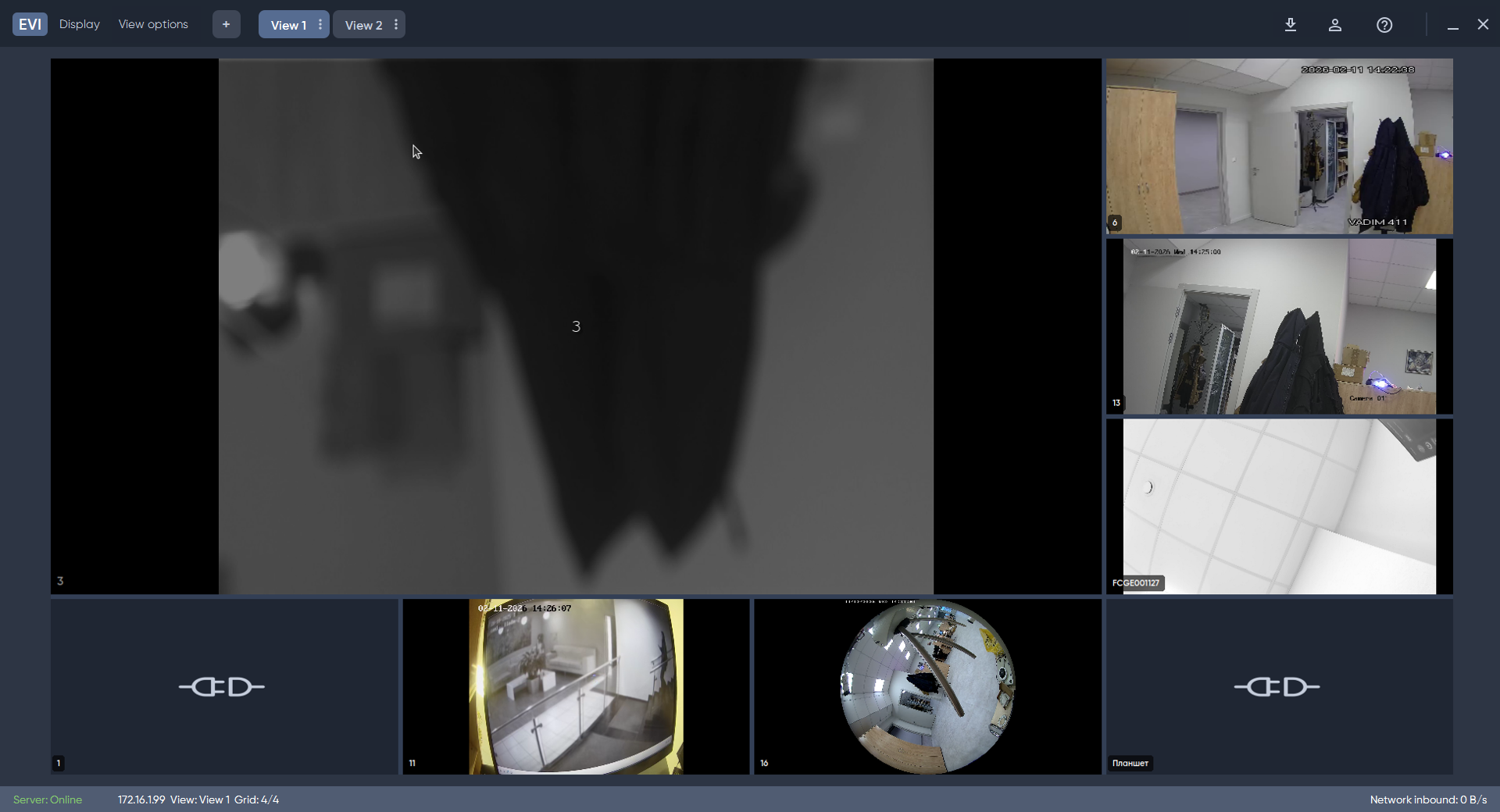
Select a section of the archive and press the Play button.
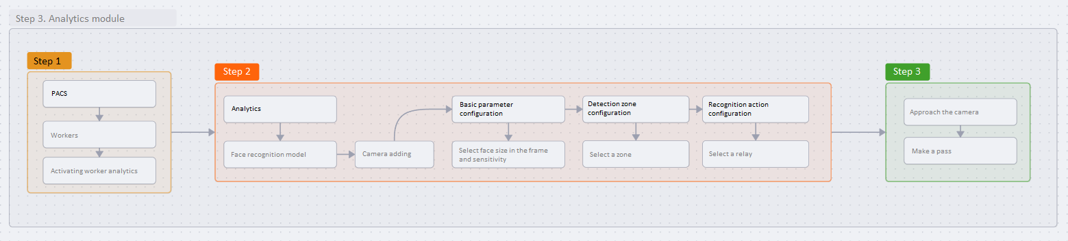
Detailed settings and recommendations for video analytics are described in the Video analytics module section.
Instructions for installing video analytics are provided in the Installing the video analytics module section of the Ubuntu 22.04.5 LTS page.
In this example, face pass is considered, if necessary, the worker can also pass through the turnstile using own pass.
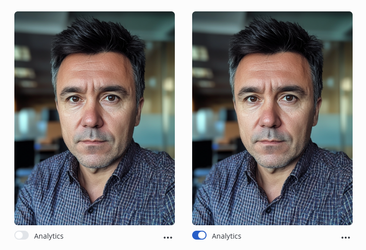
Switch to the Worker editing section.

To activate the worker's analytics, move the Analytics switch to the enabled position.
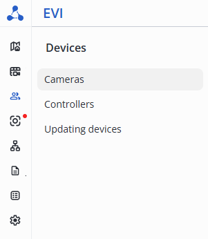
In the Devices section, go to the Cameras page.
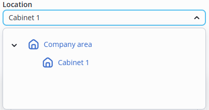
The camera location must correspond to the In location parameter of the relay to be controlled. |
Select the location of the camera.
Switch to the Video analytics page.
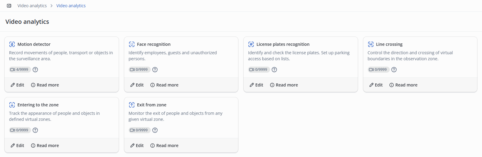
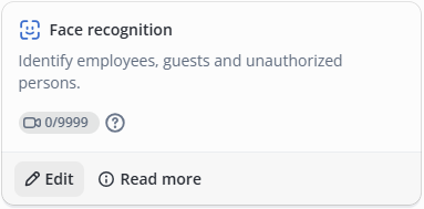
Click Edit at the Face recognition function.
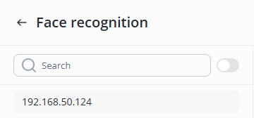
Select the desired camera from the list.
The parameter is selected by adjusting it on the live camera feed. To do this, place a person in the camera frame, positioning them directly in front of the lens, and select the area using the Set interactively button. |
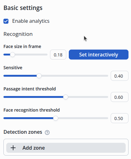
The recognition zone needs to be configured when the frame may contain multiple faces across the entire frame area.
An example of highlighting a typical area for facial recognition:
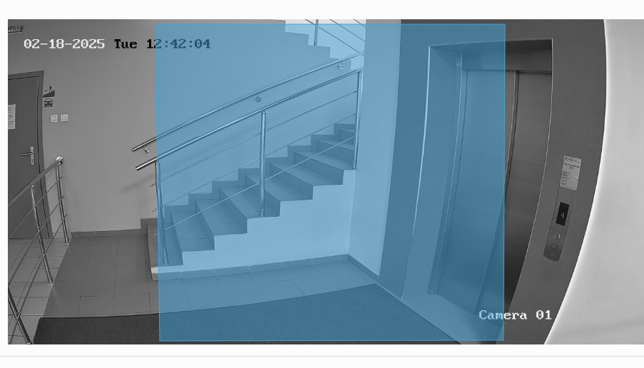
This image has the sides cut off so that the faces standing on the sides are not in the recognition area.
Switch to the Actions tab and click Add.

Next, select the action type – Relay, the required relay from the list and the relay status – Pass.
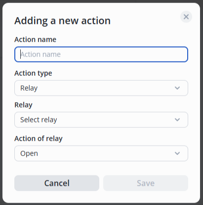
It is necessary to add the second camera in the same way and configure the passage through the turnstile in the opposite direction, using the second relay, to allow passage in both directions. |
Try to make a pass through the door. To do this, perform the following steps:
In the Journals section, the Passages page will display the worker's passage.

The Common page in the Journals section will display more detailed information about the worker passing through the door.