Firmware version 3.34.1
Introduction
MA4000-PX is a multifunctional modular node of subscriber access and aggregation. MA4000-PX is a new-generation device which incorporates various interfaces with a high density of ports for providing broadband service access. GPON technology is used for the subscriber access. ETTH (FTTB) technology is used when the device is in aggregation mode.
MA4000-PX subscriber access and aggregation node allows to create an economically profitable solution and may replace several GPON OLT LTP-8X.
This User Manual describes the purpose, general technical parameters, as well as configuring, monitoring and firmware replacement rules for MA4000-PX access node.
Product Description
Purpose
Multiservice access and aggregation node MA4000-PX is designed to construct GPON-based access networks. The system allows to construct a scalable, fault-resistant 'last mile' networks to ensure the highest safety standards, both in in urban and suburban areas. The access node manages subscriber units, traffic switching and connection to the transport network.
The central element of the MA4000-PX is the scalable L2+ Ethernet switch (PP4X), which works in cooperation with various interface modules. PLC8 optical access module is used to connect subscriber devices via GPON technology.
Key advantages of the modular architecture are as follows:
- a step-by-step network upgrade without interruptions;
- high capacity determined by an unblocked switching capacity of a node;
- handling basket modules as an integrated device.
Use cases
MA4000-PX operates as a subscriber access node. Connection with the subscriber devices is provided by the peripheral modules PLC8 featuring 8 PON ports, each of them allows connecting up to 64 subscribers. Traffic switching and connection to the transport network are ensured by PP4X central processor modules which are connected by the peripheral modules via common high-speed bus of the device. Connection with the higher level equipment is effected by means of 10G(SFP+) interfaces and 1G combined interfaces.

Figure 1 – MA4000-PX subscriber access/aggregation node use case
Delivery package
The delivery package is defined in the equipment delivery contract.
The standard delivery package includes:
- MA4000-PX equipment and SPTA set according to an order;
- User manual on CD (optional);
- Technical passport;
- Declaration of conformity.
In addition to MA4000-PX equipment, the delivery package may also include:
- RS-232 connection cable DB9F to DB9F;
- Power cord;
- DB-15M connector of the object communication interface;
- optical transceivers SFP 1Gb;
- optical transceivers SFP+ 10Gb.
MA4000-PX access node hardware
This section describes the design of MA4000-PX: it shows an exterior view of the front panel of PP4X Ethernet switch, PLC-8 interface module as well as side panels of a chassis; it describes connectors, LEDs and controls.
Chassis
MA4000-PX device is metal cased and consists of one 19” chassis with 9U height. The chassis is used for uniting modules of different functional purpose ensuring interaction of modules through high-speed 10 Gbps communication lines as well as for power distribution and supporting and monitoring temperature mode of the entire device.

Figure 2 – Front and rear views of MA4000-PX chassis

Figure 3 – Side view of MA4000-PX chassis
MA4000-PX electric power supply system does not include group devices, which would determine reliability level of the entire system as a whole. The power supply is arranged by the distribution principle – each module has its own power unit. Herewith the chassis operates only as a distributor of power to the modules.
The device has a front-to-rear ventilation system. Air flow diagram is shown in Figure 4.

Figure 4 – Air flow diagram

Figure 5 – Diagram of modules connections in a MA4000 chassis
The following designations are used in Figure 5:
- PLC – GPON interface module;
- PP4X – central switch module;
- Env – chassis controller.
The chassis composition depends on the use case. The chassis features 18 positions for modules installation. PP4X central switch module is mandatory for installation into the chassis. Up to two modules of this type can be installed to ensure the redundancy and increase the system productivity. Two central positions are intended for these modules installation (see Figure 6).

Figure 6 – MA4000-PX chassis view
The other 16 positions in the chassis are universal – any position may fit a PLC-8 interface module. Installation of the PLC-8 module is described in section GPON PLC8 interface module replacement.
To ensure interaction of modules, a cross-connect module is installed in the chassis. The module organizes interconnections between the central switches and interface modules. Each PP4X module features individual connection to the each interface module and to the neighbour module PP4X. The intermodular connections correspond to the high-speed communication channels operating at 10 Gbps speed. The system architecture shall be considered in detail in section MA4000-PX architecture.
The following elements are located in the left part of the chassis:
- Signalling connector (Telemetry input). The connector is intended for communication with an object, where the equipment is installed, and can be used for connecting various-purpose sensors with 'dry contacts' type interface as well for connecting different types of actuators.
- Two power input modules. In order to ensure the required level of reliability, the device is equiped with two power input modules, which can be connected to two different power sources. The modules ensure automatic changeover to the standby power supply in case one of the supplies fails and protection from incorrect connection of the power supply feeders. The modules design allows to replace them in the course of device operation in case of alarm. The device provides for monitoring tools for power supply modules, i.e. input voltage and consumed current.
- Grounding terminal.
Temperature control system of the device is designed to be used in combination with the air conditioning system of the equipment hall using hot and cold aisles principle. The ventilation system includes three fans arranged on the chassis rear wall (see Figure 2) and a controller to control the rotational speed of the fans. The fans controller module is installed inside the chassis.
The ventilation system performance is adjustable and can vary within the limits of 7 m3/min to 14 m3/min. The acoustic noise level — not more than 36 dB(A).
Basic technical parameters of the access platform are given in Table 1.
Table 1 – Main Specifications
General parameters | |
|---|---|
Types of modules | PP4X — control and switching module PLC8 — 8 linear interfaces GPON 2.5 Gbps |
Number of interface modules | up to 16 modules |
Bus type and performance | 34 × 10GBASE-KX (XAUI), 340 Gbps |
Control | |
Management interfaces | SNMP, CLI (Telnet, SSH, Serial) |
Physical specifications and ambient conditions | |
Power voltage | 36 .. 72 V |
Maximum power consumption | 850 W (at full load)1 chassis: 35 W PP4X: 70 W PLC8 without SFP2: 30 W PLC8 with SFP2: 40 W Fans: 18 W |
Weight | 25 kg max |
Dimensions | 480 × 400 ×350 mm |
Operating temperature range | -10 to +45 °C |
Operating humidity | relative humidity up to 80% |
Average lifetime | 20 years |
1 The maximum values for each of the modules have been considered when calculating the maximum power consumption at full load.
2 Measurements have been made for PLC8 boards, version 2v0.
PP4X central switch module
Central switch module is the main element of the platform, which generally manages and diagnoses peripheral modules, switching, aggregation and communication interface modules with higher level network equipment. Modules operate in the mode of load sharing and redundancy via two internal 10 Gbps interfaces.
The front panel external view, description of PP4X module connectors, LEDs and controls are shown in Figure 7.
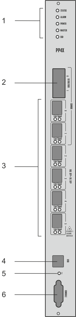
Figure 7 – Front panel external view, description of PP4X module connectors, LEDs and controls
Front panel element | Description | |
|---|---|---|
1 | Status | Device operation LED |
Alarm | Alarm LED | |
Power | Device power LED | |
Master | Device operation mode LED (master/slave) | |
SSD | SSD data storage device LED | |
2 | 10/100/1000 [0 .. 1] | 2 ports of Gigabit Ethernet (10/100/1000 Mbps) with RJ-45 connectors |
3 | [0 .. 5] | 6 slots for installing 10GBASE-X(SFP+)/ 1000BASE-X(SFP) SFP transceivers |
Link | Optical interface operation LED | |
Speed | Optical interface speed mode LED | |
4 | USB | Connector for connecting additional devices |
5 | F | Functional key that reboots the device and resets it to the factory default configuration:
|
6 | Console | RS-232 console port for local management of the device |
Two electrical Gigabit Ethernet interfaces with numbers 0, 1 and two optical interfaces with numbers 0, 1 are Combo ports. Combo ports may have only one active interface (electrical or optical) at the same time.
Technical specifications of the module are given in Table 2.
Table 2 – PP4X module technical specifications
Processor | |
|---|---|
Clock frequency | 1000 MHz |
Core quantity | 2 |
RAM | DDR2 SDRAM 512 MB 800 MHz |
Non-volatile memory | 1GB NAND Flash 2GB NAND Flash (since version 3v0) |
Interfaces | |
USB interface | Compatible with USB 2.0 specification |
Network interfaces | External connections 4 × 10GBASE-X (SFP+) 2 × (10/100/1000BASE-T/1000BASE-X (SFP)) Intermodular connections 16 × 10G XAUI (10GBASE-KX4) |
Optical transceivers | 1G SFP, 10G SFP+ |
Console port | RS-232, 115200 bps |
Ethernet switch | |
Bandwidth | 480 Gbps |
MAC table | 32K entries |
VLAN support | up to 4K in accordance with 802.1Q |
Quality of service (QoS) | 7 prioritized egress queus per port |
Number of ports | 24 ports up to 10 Gbps per port |
Port modes | Duplex/half-duplex 10/100/1000 Mbps for electrical ports Duplex mode 1/10 Gbps for optical ports |
Standards | IEEE 802.3 10BASE-T Ethernet IEEE 802.3u 100BASE-T Fast Ethernet IEEE 802.3ab 1000BASE-T Gigabit Ethernet IEEE 802.3z Fiber Gigabit Ethernet ANSI/IEEE 802.3 NWay auto-negotiation IEEE 802.3x Full Duplex and flow control IEEE 802.3ad Link aggregation IEEE 802.1p Protocol for Traffic Prioritization IEEE 802.1Q Virtual LANs IEEE 802.1ad Provider Bridges (QinQ) IEEE 802.1v VLAN Classification by Protocol and Port IEEE 802.3 ac VLAN tagging IEEE 802.1d MAC bridges IEEE 802.1w Rapid Reconfiguration of Spanning Tree IEEE 802.1s Multiple Spanning Trees IEEE 802.1x Port Based Network Access Control |
Maximum power consumption | 70 W |
PP4X module current status is displayed by Status, Alarm, Power, Master, SSD, Link, Speed LEDs. A list of LED statuses and the values thereof are shown in the following tables.
Table 3 – Light indication of the module state
LED | LED state | Device state |
|---|---|---|
Status | Solid green | Normal operation |
Green, flashing at 1 second interval | Operation in a limited mode, F button was pressed when starting the device | |
Solid red | The device is booting | |
Alarm | Off | No alarms |
Solid yellow | Non-critical alarm, one or more | |
Solid red | Critical module alarm | |
Power | Solid green | Module power is OK |
Solid red | Failure of one or more module power supply inputs | |
Off | Module power supply is not available | |
Master | Solid green | The device operates as a master device in the chassis |
Off | The device operates as a slave device | |
SSD | Solid green | Data storage carrier is connected |
Off | Carrier is not connected |
Table 4 – Combo-ports 0-1 status light indication
LED | LED state | Device state |
|---|---|---|
Link | Solid green | Connection to an oncoming device is present |
Flashing green | Data is being received or transmitted | |
Off | Port is not connected | |
Speed | Solid yellow | 1000 Mbps connection is established |
Off | If the Link LED is enabled, it means that connection at speed 10 or 100 Mbps is established |
Table 5 – Ports 2-5 status light indication
LED | LED state | Device state |
|---|---|---|
10 Gbps mode | ||
Link | Solid green | Connection to an oncoming device is present, transmitter is active |
Flashing green | Data transmission process | |
Speed | Solid yellow | 10 Gbps connection to an oncoming device is present |
Flashing yellow | Data reception | |
Indication in 1 Gbps mode | ||
Link | Solid green | Connection to an oncoming device is present |
Flashing green | Data exchange | |
Speed | Off | 1 Gbps connection to an oncoming device is present |
GPON PLC8 Interface Module
The PLC8 module is designed to organize broadband access to the data network via GPON technology at speeds of up to 2.5 Gbps in the direction to the user. This module is designed for use on the site of the 'last mile' and enables to connect up to 512 communication terminals (ONT). The front panel external view, description of PLC8 module connectors, LEDs and controls are given in Figure 8.
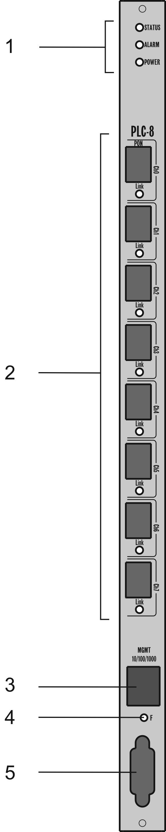
Figure 8 – Front panel external view, description of PLC8 module connectors, LEDs and controls
Front panel element | Description | |
|---|---|---|
1 | Status | Device operation LED |
Alarm | Alarm LED | |
Power | Device power LED | |
2 | PON [Ch0 .. Ch7] | 8 chassis for SFP modules of GPON |
Link | ONT connection LEDs | |
3 | MGMT 10/100/1000 | Gigabit Ethernet port (10/100/1000BASE-T) with RJ-45 connector for local control |
4 | F | Functional key that reboots the device and resets it to the factory default configuration:
|
5 | Console | RS-232 console port for local control of the device |
Table 6 – PLC8 module technical specifications
Processor | |
|---|---|
Clock frequency | 800 MHz |
Core quantity | 1 |
RAM | DDR2 SDRAM 256 MB 800 MHz |
Non-volatile memory | 32MB Serial Flash |
Interface | |
Network interfaces | External connections 2 × 10G XAUI (10GBASE-KX4) Intermodular connections 1 × 10/100/1000BASE-T RJ45 – Management port 8 × 2.5 GPON |
Console port | RS-232, 115200 bps |
SFP PON parameters | |
Connector type | SC/UPC |
Receiver sensitivity | from -28 to -8 dB |
Transmission medium | Single-mode fibre optical cable SMF 9/125, G.652 |
Optical power budget (up/downstream) | 26 dB/24.5 dB |
Minimal attenuation upstream/downstream | 11 dB/15 dB |
Optical emission spectral width upstream/downstream Δλ | 1 nm/1 nm |
Connection wave length upstream/downstream | 1310/1490 nm |
Connection speed upstream/downstream | 1.25/2.5 Gbps |
Splitting ratio | 1:4, 1:8, 1:16, 1:32, 1:64 |
Max. transmission distance | 40 km |
Ethernet switch | |
Switch performance | 128 Gbps |
MAC table | 16K entries |
VLAN support | up to 4K in accordance with 802.1Q |
Quality of service (QoS) | 7 prioritized egress queues per port |
Port modes | Duplex/half-duplex mode 10/100/1000 Mbps Duplex mode 10 Gbps for intermodular connections |
Standards | IEEE 802.3 10BASE-T Ethernet IEEE 802.3u 100BASE-T Fast Ethernet IEEE 802.3ab 1000BASE-T Gigabit Ethernet IEEE 802.3z Fiber Gigabit Ethernet ANSI/IEEE 802.3 NWay auto-negotiation IEEE 802.3x Full Duplex and flow control IEEE 802.3ad Link aggregation IEEE 802.1p Protocol for Traffic Prioritization IEEE 802.1Q Virtual LANs IEEE 802.1ad Provider Bridges (QinQ) IEEE 802.1v VLAN Classification by Protocol and Port IEEE 802.3 ac VLAN tagging IEEE 802.1d MAC bridges IEEE 802.1w Rapid Reconfiguration of Spanning Tree IEEE 802.1s Multiple Spanning Trees IEEE 802.1x Port Based Network Access Control ITU-T G.984x |
Maximum power consumption | PLC8 without SFP1: 30 W PLC8 with SFP1: 40 W |
Weight | up to 2.5 kg |
1 Measurements have been made for PLC8 boards, version 2v0.
PLC8 module current status is displayed by Status, Alarm, Power, Link LEDs. Table 7 provides possible statuses of LEDs.
Table 7 – light indication of the device
LED | LED state | Device state |
|---|---|---|
Status | Solid green | Normal operation |
Solid red | The device is booting | |
Alarm | Off | Normal operation |
Flashing red | Alarms, one or more | |
Solid red | Error on program core loading | |
Power | Solid green | Device power supply is enabled |
Link | Solid green | Connection with at least one ONT is established |
Solid red | Loss of communication with all ONTs | |
Off | Port is disabled |
Correct and error-free operation of GPON interface requires exact parameters to be chosen and set for each transceiver type. This can be done only under laboratory conditions by the terminal vendor. Table 8 lists SFP transceivers for which seamless terminal operation is guaranteed.
DDMI (Digital Diagnostic Monitoring Interface) provides information on transceiver parameters, such as temperature, power voltage, etc. DDMI also measures the level of ONT signal (RSSI). All compatible transceivers support this function.
Table 8 – List of compatible SFP transceivers
Vendor | SFP transceiver module | Class | DDMI |
|---|---|---|---|
NEOPHOTONICS | PTB38J0-6538E-SC | B+ | + |
NEOPHOTONICS | 38J0-6537E-STH1+ | C+ HP | + |
NEOPHOTONICS | 38J0-6537E-STH2+ | C+ HP | + |
NEOPHOTONICS | 38J0-6537E-STH3+ | C+ HP | + |
Ligent Photonics | LTE3680M-BC | B+ | + |
Ligent Photonics | LTE3680M-BH | B+ | + |
Ligent Photonics | LTE3680P-BC | C+ | + |
Ligent Photonics | LTE3680P-BH | C+ | + |
Ligent Photonics | LTE3680P-BC2 | C+ HP | + |
Fanghang | DLOLT43BCDS20 | B+ | + |
Fanghang | DLOLT43CCDS20 | C+ | + |
Fanghang | FH-DLT43CCDS20 | C+ | + |
MA4000-PX architecture
MA4000-PX platform is a switching device for Ethernet networks with a distributed switching system. If combined with ONT subscriber devices, MA4000-PX data transmission networks (from its architecture perspective) perform functions relating to access and aggregation levels.
MA4000-PX logical structure is shown in Figure 9.
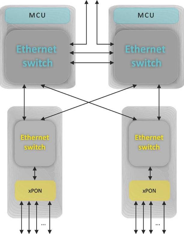
Figure 9 – MA4000-PX Access Platform Architecture
MA4000-PX is a two-level system of Ethernet switches.
The system centre has switches located on PP4X modules. They perform the aggregating function with respect to the modules of linear interfaces. The system may have one or two PP4X modules. The installation of two modules will help build a high-reliability system owing to the redundancy of switches and increase the system communications capacity due to distribution of data flows between the modules, the modules work in the stacking mode. PP4X modules stacking means there is a possibility to consolidate network interfaces, located at different modules, into trunk groups (LAG, LACP) and an integrated control interface.
The second system level: Ethernet switches located at modules of linear interfaces. These switches perform a function of aggregation with respect to the linear interfaces of a module, on which they are installed.
The interaction between modules occurs via 10Gbps connections. Each PP4X switch is connected to an interface module. Two PP4X are interconnected by two 10Gbps lines.
Access platform architecture is shown in Figure 9.
PP4X central switch module
Central switch module is the main element of the platform, which generally manages and diagnoses peripheral modules, switching, aggregation and communication interface modules with higher level network equipment. Modules operate in the mode of load sharing and redundancy via two internal 10 Gbps interfaces.
PP4X module block diagram is shown in Figure 10.

Figure 10 – PP4X module block diagram
The module comprises:
- Processor core incorporating CPU, random-access memory DDR, non-volatile memory NAND. The processor core controls local module resources, it also controls and monitors all modules incorporated into MA4000 device, stores and processes configuration data, controls and monitors the chassis. Interaction between operator and processor core during control and monitoring procedures can be achieved via RS232 console or via network interface. The connection to Ethernet switch being a part of the module is used as the processor network interface. The processor has an interface, shown as ‘shelf’ in the Figure, to provide interaction with the chassis controller. The USB interface is a universal one and can be used, e.g., for configuration data transferring and software update.
- Ethernet switch which ensures data transfer between devices and modules connected to its interfaces. The switch has 24 multimode ports which can operate at speed up to 12Gbps. The switch is controlled by a processor connected via PCI-Express interface.
- Data storage device SSD corresponds to a replaceable solid-state disk. Disks of different capacities may be used. SSD allows to store various-purpose data: configuration files of subscriber devices, system run-time journals, etc.
PP4X module features:
- Support for standard management interface through CLI, SNMP interfaces;
- Processing (changing, storing, archiving) configuration data for all device modules;
- Aggregate switch functions with the support of the following feature:
- MAC address learning/aging;
- MAC address quantity restriction;
- Unknown MAC address processing;
- Broadcast traffic restriction;
- Restricting multicast traffic;
- Quantity of multicast group up to 2000;
- Q-in-Q in accordance with IEEE 802.1ad;
- STP, RSTP, MSTP;
- Support for IGMP/MLD Proxy;
- Support for IGMP/MLD Snooping;
- Fast switching between TV programs (IGMP fast leave);
- Static routing1;
- Dynamic routing based on RIP, OSPF1 protocols;
- Bidirectional Forwarding Detect (BFD) for upstream interfaces1;
- Port isolation, Isolation of ports within one VLAN;
- Static (LAG) and dynamic (LACP) aggregation of network interfaces, including interfaces belonging to different PP4X modules;
- Data channels reservation with short recovery time (less than 1 sec) in case of failure.
- Interaction with external monitoring and control devices using Telnet, SSH, SNMP protocols;
- Collection of alarm data on interface modules and the entire device, forming accident and informational messages for monitoring systems;
- System run time logging and storaging in non-volatile memory;
- Device temperature and ventilation system control;
- Software update management for all modules of the device.
- There is a restriction (shaper) for the management interface – 500 packets per second. To ensure protection from ICMP flood, we have introduced additional restriction – 40 ICMP packets per second.
1 Not supported in the current firmware version
GPON PLC8 Interface Module
The purpose of PLC8 module is to shape the subscriber access transportation network based on GPON technology.
PLC8v2 module block diagram is shown in Figure 11.

Figure 11 – PLC8v2 module block diagram
The module includes:
- Two four-channel batch-mode processors used as GPON OLT shape up eight GPON interfaces in accordance with ITU-TG.984. Up to 64 ONT or ONU devices can be connected to each interface via optical splitters;
- Two packet Ethernet processors aggregating GPON transport flows and interacting via high-speed highway of MA4000-PX chassis with central switches. In order to ensure device reliability and increase throughput capability, PLC8 module is provided with two interfaces interacting with central switches (uplink) – one for each of them. These interfaces work in aggregated channel mode (trunk or LAG). If MA4000-PX includes only one central switch, one of the interfaces is not used;
- Processor, which tasks include coordination and monitoring of packet processors operation, processing network protocols, supporting protocols for MA4000 device centralized control.
PLC8v1 module block diagram is shown in Figure 12.

Figure 12 – PLC8v1 module block diagram
The module includes:
- Two four-channel batch-mode processors used as GPON OLT shape up eight GPON interfaces in accordance with ITU-TG.984. Up to 64 ONT or ONU devices can be connected to each interface via optical splitters;
- Packet Ethernet processor aggregating GPON transport flows and interacting via high-speed highway of MA4000-PX chassis with central switches. In order to ensure device reliability and increase throughput capability, PLC8 module is provided with two interfaces interacting with central switches (uplink) – one for each of them. These interfaces work in aggregated channel mode (trunk or LAG). If MA4000-PX includes only one central switch, one of the interfaces is not used;
- Processor, which tasks include coordination and monitoring of packet processors operation, processing network protocols, supporting protocols for MA4000 device centralized control.
Installation and connection
This Section provides safety instructions, procedures for equipment installation into a rack and connection to power supply.
Prior to beginning the work it is necessary to carefully study working instructions and recommendations contained in equipment documentation.
Along with the safety requirements specified in this document and other documents accompanying the equipment, all industry relevant laws and regulations as well as operating company’s individual requirements shall be observed when operating the equipment.
The personnel operating the equipment shall undergo relevant safety and operations training. Equipment may be handled by qualified personnel only.
In order to preclude personnel injuries and damage of equipment, all works shall be carried out in accordance with the following requirements.
General requirements
Equipment installation:
- devices should be installed in the premises, which help prevent unauthorized access to them;
- devices can be installed only above concrete or other surfaces that do not sustain combustion;
- prior to beginning operation the device should be put steadily on a steady surface – on the floor or in a telecommunication cabinet;
- special attention to grounding should be given during installation/uninstallation of the device. The grounding wire should be primarily connected to the device during installation and disconnected last during uninstallation;
- for trouble-free operation of the equipment, a proper ventilation should be ensured. There should be no foreign objects closer than 5 cm to ventilation openings available on equipment body;
- all the fasteners should be tightened sufficiently after completing installation works.
Grouding:
- operating the device without correctly arranged grounding is not allowed. The grounding should be arranged in accordance with Electrical Installations Code (EIC) requirements and shall be tested to comply with the Code requirements;
- a device or an equipment complex should be connected to the protective grounding prior to operation (prior to connecting power supply feeders). The section of grounding conductors should be at least than 10 mm2;
- in case additional instruments and devices are used together with the equipment which are powered from high-voltage mains, e.g., from 220 VAC mains, then such instruments should be reliably grounded for protecting personnel and preserving equipment integrity.
Power supplies:
- the device requires a DC power source;
- to connect power supplies, wires with sections corresponding to the maximum value of current used by a device should be used;
- adherence to polarity is mandatory when connecting power feeders;
- available power supplies should have protective devices to ensure quick load disconnection in case the maximum value for the device feed current had been exceeded;
- each power feeder should be connected via a device which allows to promptly switch off – a circuit breaker or any other device;
- the device features two power inputs and can be connected to one or both power supplies. In order to switch off the device completely, it is necessary to disable all used power supplies.
Personnel safety:
- no mounting or other works related to disconnection of cables from the device or disconnection of the device from the grounding circuits should be performed during thunderstorm;
- to lift or move the device hold it by the chassis elements. Do not load pushers by the basket weight at the front panels of modules and handles on the replacement in-feed modules and ventilation panel;
- two persons should be engaged to move the basket;
- to protect eyes from laser radiation, do not look into in the open optical ports. Infrared radiation of the lasers used in optical interfaces of devices can cause irreversible eye damage.
Personnel qualification:
- device installation, configuring and servicing shall be performed by qualified employees only;
- the device may be handle authorized personnel only;
- any changes to the device (replacement of modules, software replacement) can be made by properly qualified and attested personnel;
- any alarms or failures in equipment operation shall immediately be reported to the on-duty personnel.
Prior to perform any types of works, all sections of documentation should be carefully read.
Equipment installation
Preparing for installation
Prior to equipment installation ensure that mounting location requirements are met. No high temperatures, dust, harmful gases, combustible and explosive materials, sources of intensive electromagnetic radiation (radio stations, transformer substations, etc.), sources of loud sound shall be found at the places of equipment installation.
The installation place shall be compliant with the typical requirements to the places of telecommunication equipment installation.
If temperature in the premises without equipment exceeds 35 °C, an air conditioner it should be additionally installed. The air conditioner shall automatically start-up after blackouts. A stream of cooled air shall not blow right to the equipment, instead it shall be uniformly distributed within the premises.
The device ventilation is organized following a diagram shown in Figure 4.
The following conditions should be met for proper operation of the ventilation system:
- distance between the lower and the upper panels of the chassis and the closest neighbouring equipment should be at least 1U (44.45 mm);
- distance between the rear panel of the chassis and the rear panel of the wall should be at least than 200 mm;
- grounding shall be arranged in the installation premises, the power supply system shall correspond to equipment characteristics with respect to consumed power.
Position and mounting requirements
The device is intended to be installed in telecommunication cabinet. For maintenance operations, a free access to the device from the front and the rear should be provided.
Example for equipment arrangement is shown in Figure 13.
Figure 13 – Example of positioning
Installing into a rack
The chassis of the device has attachment brackets intended for installation into telecommunication cabinet (19-inch rack). The delivery set of the device includes fasteners.
The ventilation requirements above should be met when arranging equipment in a rack. Figure 14 shows an example for device arrangement in the rack.

Figure 14 – MA4000-PX rack installation
Laying and connecting cables
This Section explains an internal connections order to be made in the telecommunication cabinet.
Before connecting power feeders and communication lines to the device, grounding conductors should be connected first.
Telecommunication cabinet shall be grounded prior to perform works on feeding power to the devices.
At the next step power cables should be connected. One or two power feeders may be connected to the device. During connection works, adherence to polarity should be ensured at all the stages.
All power sources should be disabled when performing power connection works.
To supply power to the devices installed in the cabinet, a power distribution device should be used. The equipment wiring diagram with a distribution device depends on its parameters. An approximate cable laying diagram is shown in Figure 15.

Figure 15 – Cable laying and connecting and wire grounding diagram
- Red – wire connecting device terminal '+' with positive power supply pole;
- Blue – wire connecting device terminal '-' with negative power supply pole;
- Yellow – grounding wire (grounding terminals at the device and grounding bar are marked with a
 sign).
The next step involves connection of subscriber lines and data transmission lines. The lines should be connected in accordance with the design diagram.
Data transmission lines should be connected to the ports at PP4X control modules. An optical or copper wire can be used for connection works.
In case of laying optical cable outside the cabinet and leading it into the cabinet, measures should be taken to protect the cable from damages by means of laying cable in the protective corrugated pipe. Cable bending radius when laying should be not less than 40 mm. Cable organizers should be used for horizontal cable laying in the equipment approach area.
In case of laying copper (electric cable) special attention should be paid to protection of cable insulation and sheath from damage. The windows for cable feed-in into the cabinet should be free from sharp cutting edges. In all cases laying of signal cables and data transmission cables in the same bundle with power cables should be avoided.
Connecting to the CLI
Introduction
This section describes various connection methods for Command Line Interface (CLI) of the access node.
A serial port (hereafter – COM port) is recommended for preliminary adjustment of the access node.
Connecting to the CLI via COM port
This type of connection requires PC either to have an integrated COM port or to be supplied with an USB-COM adapter cable. The PC should also have a terminal program installed, e. g. HyperTerminal.
Step 1. Using the null modem cable, connect the CONSOLE port of the PP4X master module ('Master' LED indicator should be solid green) to the COM port of the PC, see Figure 16.
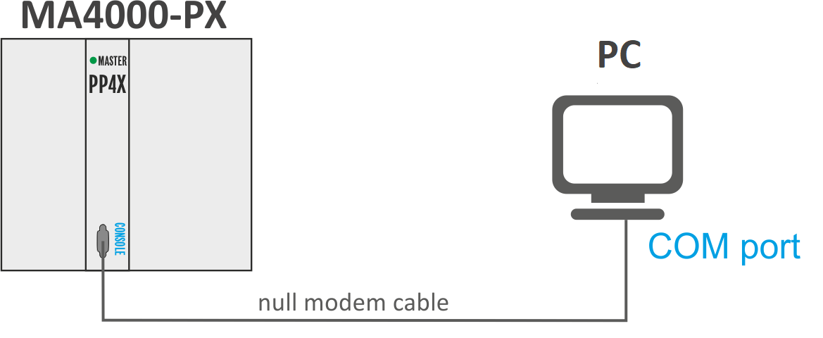
Figure 16 – Connecting access node to PC via COM port
Step 2. Launch the terminal program and create a new connection. Select the corresponding COM port in the 'Connect to' drop-down list. Assign the port settings according to the Table 9. Click OK.
Table 9 – COM port specifications
Parameters | Value |
|---|---|
Speed | 115200 |
Data bits | 8 |
Parity | none |
Stop bits | 1 |
Flow control | none |
Step 3. Press Enter. Log into the device CLI.
Factory settings:
- login: admin
- password: password
********************************************
*            Welcome to MA4000             *
********************************************

ma4000 login: admin
Password: ********


Technical support: http://eltex.nsk.ru/support
Wed Jan  8 11:58:08 T 2014

ma4000#
Connecting to the CLI via Telnet
The Telnet protocol connection is more flexible than the connection via COM port. Connection to CLI can be established directly at the device location or via an IP network with the help of a remote desktop.
This section considers direct connection to CLI at the terminal location. Remote connection is similar, but requires changes in the access node IP address that will be considered in detail in the Network settings section.
In order to be connected to the access node, a PC should have a Network Interface Card (NIC). The connection will additionally require the sufficient amount of network cable (Patching Cord RJ45) as it is not included in the delivery package.
Step 1. Connect the network cable to the Gigabit Ethernet port 0 or 1 (RJ-45 connector) of the PP4X master module ('Master' LED should be solid green) and to the PC's network card, see Figure 17.

Figure 17 – Connecting access node to PC with the network cable
Step 2. Assign IP settings for network connections:
- IP address: 192.168.1.1
- Subnet mask: 255.255.255.0

Figure 18 – Network connection configuration
Step 3. On the PC, click Start > Run. Enter the telnet command and IP address of the access node. IP address factory setting: 192.168.1.2. Click OK.

Figure 19 – Launching Telnet client
Step 4. Log into the access node CLI.
Factory settings:
- login: admin
- password: password
********************************************
*            Welcome to MA4000             *
********************************************

ma4000 login: admin
Password:

Technical support: http://eltex.nsk.ru/support
Mon Jan 13 13:40:02 T 2014

ma4000#
Connecting to the CLI via Secure Shell
Secure Shell (SSH) connection has functionality similar to the Telnet protocol. However, as opposed to Telnet, Secure Shell encrypts all traffic data, including passwords. This enables secure remote connection via public IP networks.
This section considers direct connection to CLI at the terminal location. Remote connection is similar, but requires changes in the access node IP address that will be considered in detail in the Network settings section.
In order to be connected to the access node, a PC should have a Network Interface Card (NIC). The PC should have an SSH client installed, e. g. PuTTY. The connection will additionally require the sufficient amount of network cable (Patching Cord RJ45) as it is not included in the delivery package.
Step 1. Perform Steps 1 and 2 from Section Connecting to CLI via Telnet protocol.
Step 2. Run PuTTY. Enter IP address of the access node.
- IP address factory setting: 192.168.1.2;
- Port – 22;
- Protocol type – SSH.
Click Open.

Figure 20 – SSH client startup
Step 3. Log into the access node CLI.
Factory settings:
- login: admin
- password: password
********************************************
*            Welcome to MA4000             *
********************************************

ma4000 login: admin
Password:


Technical support: http://eltex.nsk.ru/support
Mon Jan 13 13:40:02 T 2014

ma4000#
Getting started with the CLI
Introduction
CLI is the main means of communication between user and the access node. This section considers general rules in operations with CLI.
Command Line Interface (CLI) allows to perform the device management and monitor its operation and status. You will require the PC application supporting Telnet protocol operation or direct connection via the console port (e.g. HyperTerminal).
Command line operation rules
To simplify the use of the command line, the interface supports automatic command completion. This function is activated when the command is incomplete and the <Tab> character is entered.
Another function that helps to use the command line – context help. At any stage of entering a command, you can get a prompt about the following command elements by entering <?> character.
For the convenience of managing the device via a command line, the do command is used, which allows you to execute global level commands (ROOT) when you are at other levels of the command interface.
For example:
ma4000# configure		switch to the device configuration mode
ma4000(config)# vlan 1
ma4000(vlan-1)# do show vlan 1

   Vlans:
   ~~~~~~
VID    Name                   Tagged                           Untagged
-   -----------------   -----------------------------   ------------------------------
1    VLAN0001          slot-channel 0            (M)    front-port 1/0            (S)
                       slot-channel 1            (M)    front-port 1/1            (S)
                       slot-channel 2            (M)    front-port 1/2            (S)
…

                       plc-pon-port 0/7          (D)    -
                       plc-slot-channel 0/0      (D)    -
----   -------------   ------------------------------   ------------------------------

Membership type: (S) - static, (D) - dynamic, (M) - slot-channels in management vlan
To simplify the commands, the whole command system has a hierarchical structure. There are special branch commands for transition between levels of the hierarchy. This allows to use brief commands on each level. To designate a current level where a user is located, the system prompt string changes dynamically.
For example:
ma4000# configure		enter the device configuration mode
ma4000(config)#
ma4000(config)# exit	return to the highest command system layer
ma4000#
For the ease of command line use, shortcut keys listed in the Table 10 are supported.
Table 10 – Description of CLI shortcut keys
Shortcut key | Description |
|---|---|
Ctrl+D | In the nested section, return to the previous section ('exit' command); in the root section, exit the CLI ('logout' command). |
Ctrl+Z1 | Go to the root section |
Ctrl+A | Transition to the beginning of line |
Ctrl+E | Transition to the end of line |
Ctrl+U | Removal of characters to the left of a cursor |
Ctrl+K | Removal of characters to the right of a cursor |
Ctrl+C | Clear the line |
Ctrl+W | Remove a word |
Ctrl+B1 | Transition of a cursor one position backwards |
Ctrl+F1 | Transition of a cursor one position ahead |
1 Not supported in the current firmware version.
Command line interface enables user authorization and restricts access to commands depending on their access level, provided by the administrator.
You can create as many users as you like, access rights will be assigned individually to each user.
In factory configuration, the system includes one user with the 'admin' name and the 'password' password.
The system supports multi-user privileged access.
CLI commands structure
MA4000 command line interface command system is divided into the hierarchical levels – modes (view).
From the global ROOT mode, you can enter the device parameters' configuration mode – CONFIG mode. Only users with the access level 15 are able to enter the configuration mode.
To switch from the global mode ROOT, you should run the following commands:
ma4000# configure terminal
ma4000(config)#

Figure 21 – Command mode hierarchy
Top level of the command hierarchy is shown in the Table 11.
Table 11 – Command modes hierarchy (top level)
Level | Entry command | Prompt line view | Previous level |
|---|---|---|---|
Global mode (ROOT) | ma4000# | ||
MA4000 configuration management mode (CONFIG) | configure terminal | ma4000(config)# | ROOT |
Interface configuration | For detailed information see Table 12 | CONFIG | |
Profiles management | For detailed information see Table 13 | CONFIG | |
VLAN configuration (VLAN) | vlan | ma4000(vlan-N)# | CONFIG |
Table 12 – Interface configuration command modes
Level | Entry command | Prompt line view | Previous level |
|---|---|---|---|
PP4X module external uplink interface configuration (FRONT-PORT) | interface front-port | ma4000(front-port _)# | CONFIG |
Configuration of PLC8 module external GPON interfaces (GPON-PORT) | interface gpon-port | ma4000(gpon-port _)# | |
ONT GPON configuration (PLC ONT) | ont | ma4000(config)(if-ont-0/0/0)# | |
Configuration of PLC8 module external management interface (mgmt) (PLC FRONT-PORT) | interface plc-front-port | ma4000 (plc-front-port-x)# | |
Configuration of management interfaces located between the Ethernet switch and PLC8 module olt chips (PLC MGMT-PON-PORT) | interface plc-mgmt-pon-port | ma4000 (plc-mgmt-pon-port-x)# | |
Configuration of PON interfaces located between the Ethernet switch and PLC8 module OLT chips (PLC PON-PORT) | interface plc-pon-port | ma4000 (plc-pon-port-x)# | |
Configuration of the PLC8 module interface aggregation group used for connection to the PP4X module (PLC SLOT-CHANNEL) | Interface plc-slot-channel | ma4000(plc-slot-channel-x)# | |
Configuration of PLC8 module interfaces used for connection to PP4X (PLC SLOT-PORT) | interface plc-slot-port | ma4000 (plc-slot-port-x)# | |
LAG configuration of PP4X module uplink interfaces (PORT-CHANNEL) | interface port-channel | ma4000(port-channel-_)# | |
LAG configuration of PP4X module interfaces for PLC8 modules (SLOT-CHANNEL) | interface slot-channel | ma4000(slot-channel-_)# | |
Configuration of PP4X module interfaces for PLC8 modules (SLOT-PORT) | interface slot-port | ma4000(slot-port-_)# | |
Configuration of PP4X module internal stacking interfaces (STACK-PORT) | interface stack-port | ma4000(stack-port-_)# |
Table 13 – Device profile command mode description
Level | Entry command | Prompt line view | Previous level |
|---|---|---|---|
Address table profile configuration (PROFILE ADDRESS TABLE) | profile address_table | ma4000(config-address-table)(" NAME ")# | CONFIG |
ONT GEM port profile configuration (PROFILE CROSS CONNECT) | profile cross-connect | ma4000(config-cross-connect)("NAME")# | |
DBA profile configuration (PROFILE DBA) | profile dba | ma4000(config-dba)("NAME")# | |
DHCP relay agent profile configuration (PROFILE DHCP_RA) | profile dhcp_ra | ma4000(config-dhcp-ra)("NAME")# | |
ONT management profile configuration (PROFILE MANAGEMENT) | profile management profile management-by-name | ma4000(config-management)("NAME")# | |
DHCPv6 relay agent profile configuration (PROFILE DHCP_RA) | profile dhcpv6-ra | ma4000(config-dhcpv6-ra)("NAME")# | |
ONT port profile configuration (PROFILE PORTS) | profile ports | ma4000(config-ports)("NAME")# | |
PPPoE intermediate agent profile configuration (PROFILE PPPoE_IA) | profile pppoe_ia | ma4000(config-pppoe-ia)("NAME")# | |
ONT bandwidth management profile configuration (PROFILE SHAPING) | profile shaping | (config-shaping)("NAME")# | |
VLAN profile configuration (PROFILE VLAN) | profile vlan | ma4000(config-vlan)("NAME")# |
Configuring access node
Configuration structure
Introduction
A collection of all access node settings is referred to as configuration. This section provides information about the parts configuration consists of. It also defines the lifecycle of configuration and describes main operations which can be performed.
Configuration structure
The access node configuration can be conventionally divided into 3 parts. Figure 22 shows the configuration structure.

Figure 22 – The structure of access node configuration
- General system part. This group includes such settings as: network, service settings, user table, etc.
- SLOT – Slot configuration. Contains PLC8 interface module settings.
- Profiles – OLT and ONT profiles. Contains OLT and ONT profile settings, that could be assigned to the PLC8 interface modules and ONT subscriber terminals respectively.
Configuration lifecycle
There are several types of configuration in the system:
- CANDIDATE – a configuration under review.
- RUNNING – an active configuration. It refers to the current configuration of the access node.
- BACKUP – keeps the previous active configuration; used when you need to roll back configuration changes.
Figure 23 shows the diagram of configuration type changes.
Figure 23 – Diagram of configuration type changes
To apply changes made to the configuration, you should execute the commit command. After that, running configuration becomes backup configuration, and RUNNING is copied to BACKUP.
If you need to cancel configuration changes made, perform the rollback operation. After that, the CANDIDATE configuration will be deleted. Next time configuration changes will be based on the RUNNING configuration.
To validate the applied configuration, the operator should enter the confirm command. If the confirmation is not provided until the expiration of the confirmation timer (default value is 5 minutes), the device configuration will return to the state before the last commit command execution. You can roll back configuration changes before the timer expires. To do that, use the restore command.
Creating a configuration backup
Configuration backups allow the access node operation to be quickly restored after abnormal situations or replacement. Manual or triggered (on events) creation of backups is recommended at a regular basis.
Access node configuration is uploaded to a TFTP server available in management network. The copy command is used to upload the data. Pass the uploaded device configuration fs://backup and destination URI as parameters.
ma4000# copy fs://backup tftp://192.168.22.1/config
To create backups automatically, you have to configure special events (triggers).
Step 1. If necessary, define the configuration backup upload on each change (on the commit command execution) with the backup onchange command:
ma4000(config)# backup onchange
Step 2. If necessary, define the configuration backup upload on timer with the backup ontimer command. Set the configuration backup upload timer with the backup ontimer-period command. Pass the timer value in seconds as a parameter:
ma4000(config)# backup ontimer
ma4000(config)# backup ontimer-period 3600
Step 3. Specify the URI for configuration upload:
ma4000(config)# backup path tftp://192.168.22.1/config
Step 4. Apply and confirm changes:
ma4000(config)# do commit
ma4000(config)# do confirm
Recovering configuration
Access node configuration is restored from a TFTP server available in management network. The copy command is used to restore the data.
Step 1. Load configuration using the copy command. Pass the restored configuration source URI and fs://backup as parameters:
ma4000# copy tftp://192.168.22.1/config fs://backup
Step 2. Apply and confirm changes:
ma4000# commit
ma4000# confirm
Reseting configuration
To reset an access node configuration to factory settings, use the default command:
ma4000# default
    Entire candidate configuration will be reset to default, all settings will be lost upon commit. Additional firmware will be deleted.
Do you really want to continue ? y/n y
Network settings
Introduction
This section describes adjustment of network settings for an access node. Adjusting network settings enables remote control and integration with OSS/BSS systems.
Configuring network parameters
Adjustments of network settings are recommended to be done via COM port connection, described in Section Connecting to the CLI via COM port. This will prevent issues with connection loss before the access node being adjusted. Be very careful when using remote adjustment.
Step 1. Use the show management command to view the current network settings:
ma4000#show management
Network parameters :
        ip            192.168.0.1
        mask          255.255.255.0
        gateway       192.168.0.254
        vlan          1
Step 2. Switch to the configure view and set the access node name by using the hostname command:
ma4000# configure terminal
ma4000(config)# hostname ma4000
Step 3. Set the access node IP address by using the management ip command. Pass the IP address and the subnet mask as parameters:
ma4000(config)# management ip 192.168.22.22 255.0.0.0
Step 4. Set the default gateway by using the management gateway command:
ma4000(config)# management gateway 192.168.22.254
Step 5. Adjust the VLAN management of the access node by using the management vlan command, if necessary:
ma4000(config)# management vlan 9
Proper operation of the inband management function requires VLAN adjustment as described in section VLAN configuration.
Step 6. Set the lifetime of MAC addresses by using the mac address-table aging-time command. Pass time in seconds as a parameter:
ma4000(config)# mac address-table aging-time 600
Step 7. The network settings will change as soon as the configuration is applied. No access node reboot is needed:
ma4000(config)# do commit
ma4000(config)# do confirm
Managing users
Introduction
This section is devoted to management of the access node users.
The factory settings provide only one user, i. e. the device administrator.
login: admin
password: password
When you start to configure the access node, we recommend you to change the password of the admin user.
For security reasons, there is a strictly defined set of permissions, which can be delegated to access node users. For these purposes, each user gets his own level of privileges. Level 0 corresponds to a minimum set of permissions, Level 15 – to a maximum set of permissions.
CLI commands are ranked by the level of privileges. Level 0 commands are available to all users. Level 15 commands are available only to Level 15 users. Commands available to the user will correspond to his/her privilege level. Privilege list and description:
- view-switch – allows to view PP4X switch and slot configuration;
- view-alarm – allows to view active alarms, their configuration and event log;
- view-system – allows to view system settings: logging, user configuration, Tacacs;
- view-general: allows to view basic settings – management, firmware information, status of boards and log message reading;
- view-gpon – allows to view configuration and status of OLT chips, GPON ports, and OLT;
- view-ont – allows to view MAC tables and ONT counters;
- view-ont-profile – allows to view ONT profile configuration;
- view-switch-interfaces – enables Ethernet interface operation monitoring: counters; Ethernet port status, utilization and configuration; MAC table configuration;
- config-switch – enables switch configuration: LACP, QoS, STP;
- config-alarm – enables alarm configuration;
- config-system – enables configuration of system parameters: logging, user configuration, Tacacs;
- config-general – enables configuration of management parameters and operations with software;
- config-gpon – enables configuration of OLT profiles and configuration of OLT chip basic operation parameters;
- config-ont – enables ONT configuration: adding, removing, service activation;
- ont-operation – allows to execute specific ONT management commands: reboot, reconfiguration, firmware update;
- config-ont-profile – enables configuration of ONT profiles;
- config-switch-interfaces – enables Ethernet interface configuration: aggregation, enabling/disabling, VLAN operations.
Users list preview
To view the list of access node users, enter the show users config command:
ma4000# show users config

   System users
   ~~~~~~~~~~~~
User name              User privilege level
--------------------   ----------------------------------------
root                   15
admin                  15
remote                 15
linux                  0
4 system users.
The admin, root and linux users always exist and cannot be deleted or duplicated. The node supports up to 16 users.
Adding a new user
In order to operate effectively and safely, the access node, as a rule, requires one or several additional users. To add a new user, enter the user command in the configure view:
ma4000(config)# user operator
ma4000(config)# do commit
ma4000(config)# do show users

   System users
   ~~~~~~~~~~~~
User name              User privilege level
--------------------   ----------------------------------------
root                   15
admin                  15
remote                 15
linux                  0
operator               0
5 system users.
Pass the name of the new user to the user command as a parameter. The name should not be longer than 32 characters. The name should not contain special characters.
Changing user password
To change user password, enter the user command. Pass the user name and a new password as parameters:
ma4000(config)# user operator password newpassword
Maximum password length is 31 characters. If the password contains a space, use quotations for the password.
Viewing and changing user access rights
To manage user access rights, a user priority system is implemented.
A newly created user is granted with a minimal set of permissions:
ma4000(config)#  user  operator
ma4000(config)# do show users
ma4000(config)# do show users

   System users
   ~~~~~~~~~~~~
User name              User privilege level
--------------------   ----------------------------------------
root                   15
admin                  15
remote                 15
linux                  0
operator               0
5 system users.
To change the user priority level, enter the user command. Pass the user name and a new priority as parameters:
ma4000(config)# user operator privilege 15
ma4000(config)# do show users

   System users
   ~~~~~~~~~~~~
User name              User privilege level
--------------------   ----------------------------------------
root                   15
admin                  15
remote                 15
linux                  0
operator               15
5 system users.
Deleting a user
To delete a user, enter the no user command in the configure view. Pass the user name as a parameter:
ma4000# configure terminal
ma4000(config)# no user operator
ma4000(config)# do commit
ma4000(config)# do confirm
Configuring user session
Timeouts are used to limit the duration of CLI sessions. If no commands are executed before the timeout, the session will be closed automatically. Use the cli session-timeout from the configure view command. Pass the time period in minutes as a parameter.
ma4000(config)# cli session-timeout 300
Configuring user authentication
There are several methods of user authentication in the system:
- do not use authentication;
- local – use a local user database for authentication;
- tacacs+ – use TACACS+ server for authentication;
- radius – use RADIUS server for authentication.
Step 1. Define the default authentication procedure using the aaa authentication login command:
ma4000(config)# aaa authentication login default tacacs+
In this example, the system will attempt to perform authentication using the Tacacs+ server in the first place (see Section Tacacs+ configuration). If the server is unavailable, the authentication will be performed using the local user database.
Step 2. Switch to configuration of the connection method, e.g. the console:
ma4000(config)# line console
Step 3. Define the authentication procedure for the selected method. You can use the default authentication procedure or a custom procedure, created by analogy to the Step 1:
ma4000(config)# line console
ma4000(config-line-console)# login authentication default
Step 4. Apply the configuration by using the commit command:
ma4000(config)# do commit
ma4000(config)# do confirm
Network access restriction
To improve security and restrict access to the device by persons not intended for its maintenance, the management access-list functionality is used.
There are two options for this functionality: default allow (default behavior) – all non-restricted traffic will be processed, default deny – all unauthorized traffic will be discarded.
Example. Restrict access to the device for a specific subnet.
Let's forbid management of the device except by means of ssh protocol, traffic from subnet 10.0.0.0/24 coming to front-port 1/0.
Step 1. Restrict all unauthorized traffic:
ma4000(config)# management access-list default deny
Step 2. Configure restrictive criteria:
ma4000(config)# management access-list-ip
ma4000(acl-ip)# add allow ssh front-port 1/0 10.0.0.0 255.255.255.0
Step 3. Apply changes:
ma4000(acl-ip)# do commit
ma4000(acl-ip)# do confirm
Service configuration
SNMP configuration
Step 1. Enable SNMP agent using the ip snmp agent enable command:
ma4000(config)# ip snmp agent enable
Step 2. Define the SNMP device name using the ip snmp agent system name command:
ma4000(config)# ip snmp agent system name ma4000
Step 3. Define SNMPv3 EngineID:
ma4000(config)# ip snmp agent engine id test
Step 4. Define the SNMP trap destination server. Pass SNMP Trap version and destination IP address as parameters:
ma4000(config)# ip snmp agent traps informs 192.168.1.100
Step 5. Define SNMPv2 community, if necessary:
ma4000(config)# ip snmp agent community readonly public
Step 6. Add SNMPv3 users using the ip snmp agent user add command. Pass username, password (8-31 symbols) and access mode as parameters:
ma4000(config)# ip snmp agent user add test test ro
Step 7. If necessary, change the type of transport protocol for SNMP messages transmission. By default the messages are sent in UDP.
ma4000 (config)# ip snmp agent transport tcp
Step 8. Apply the configuration using the commit command:
ma4000(config)# do commit
ma4000(config)# do confirm
System log configuration
Step 1. Define the level of messages, that will be sent to the console and the remote CLI sessions (SSH and Telnet):
ma4000(config)# logging console debug
ma4000(config)# logging monitor debug
Step 2. Define the maximum system log file size. When the file size is exceeded, the system will perform the rotation:
ma4000(config)# logging file-size 1000
Step 3. Define the quantity of system log files of the same type:
ma4000(config)# logging max-files 5
Step 4. If necessary, perform the message level configuration for the files listed in the Table 24:
ma4000(config)# logging file pp debug
Step 5. If necessary, perform the message filter configuration for the files listed in the Table 24 using the match command. Use the destination command to define the destination for messages:
ma4000(config)# logging builtin-filter pp
ma4000(config-log-filter-pp)# match pp
ma4000(config-log-filter-pp)# destination file pp
ma4000(config-log-filter-pp)# destination host 192.168.1.100 port 55 transport udp
Step 6. If necessary, enable system log message forwarding to the remote SYSLOG server:
ma4000(config-log-filter-pp)# exit
ma4000(config)# logging host 192.168.1.120 port 55 transport udp debug
Step 7. If necessary, enable the system log file storage to the non-volatile memory:
ma4000(config)# logging storage persistent
Step 8. If necessary, configure the message level on each PLC:
ma4000(config)# logging filter slot2
ma4000(pp4x-config-log-filter-slot2)# facility any debug
ma4000(pp4x-config-log-filter-slot2)# exit
Step 9. Apply the configuration using the commit command:
ma4000(config)# do commit
ma4000(config)# do confirm
SSH configuration
Step 1. Enable SSH server using the ip ssh server command:
ma4000(config)# ip ssh server
Step 2. Apply the configuration by using the commit command:
ma4000(config)# do commit
ma4000(config)# do confirm
Telnet configuration
Step 1. Enable Telnet server using the ip telnet server command:
ma4000(config)# ip telnet server
Step 2. Specify the connection port using the ip telnet port command:
ma4000(config)# ip telnet port 9000
Step 3. Apply the configuration by using the commit command:
ma4000(config)# do commit
ma4000(config)# do confirm
Tacacs+ configuration
Step 1. Define the Tacacs server connection settings:
ma4000(config)# tacacs-server timeout 10
ma4000(config)# tacacs-server key 12345
ma4000(config)# tacacs-server encrypted key 98C7D37909
Step 2. Add Tacacs server into the list of utilized servers using the tacacs-server host command. Define the connection settings for this server:
ma4000(config)# tacacs-server host 192.168.1.200
ma4000(config-tacacs)# key 123
ma4000(config-tacacs)# timeout 12
ma4000(config-tacacs)# priority 0
ma4000(config-tacacs)# port-number 3000
Step 3. If necessary, enable accounting for commands entered by the user:
ma4000(config)# aaa accounting commands tacacs+
Step 4. If necessary, enable accounting for user logins/logouts:
ma4000(config)# aaa accounting start-stop tacacs+
Step 5. Apply the configuration using the commit command:
ma4000(config)# do commit
Radius configuration
Step 1. Define common parameters of connection to Radius servers:
ma4000(config)# radius-server timeout 10
ma4000(config)# radius-server key 12345
ma4000(config)# radius-server encrypted key 98C7D37909
Step 2. Add Radius server into the list of utilized servers using the radius-server host command. Define the connection settings for this server:
ma4000(config)# radius-server host 192.168.1.200
ma4000(config-radius)# key 123
ma4000(config-radius)# timeout 12
ma4000(config-radius)# priority 0
ma4000(config-radius)# port-number 3000
Step 3. Apply the configuration using the commit command:
ma4000(config)# do commit
SNTP configuration
Step 1. Enable time synchronization using the ip sntp client command:
ma4000(config)# ip sntp client
Step 2. Define the time synchronization server IP address using the ip sntp server command:
ma4000(config)# ip sntp server 192.168.1.254
Step 3. Specify the synchronization interval in minutes:
ma4000(config)# ip sntp poll-period 60
Step 4. Apply the configuration by using the commit command:
ma4000(config)# do commit
ma4000(config)# do confirm
Daylight saving change configuration
The device allows you to flexibly adjust the transition to daylight saving time and back. There are 2 possible configuration options:
- clock summer-time date – hard bind to a specific date.
Example: to schedule time transfer at +1 hour on December 3 at 00:00 and back on March 16 00:00 from 2015 to 2035.
clock summer-time date zone TEST start-day 3 start-month dec start-year 2015 start-time 00:00 end-day 16 end-month mar end-year 2035 end-time 00:00 hours 1 minutes 0
- clock summer-time recurring – bind to a floatation date
Example: to schedule time transfer for +1 hour on the third Saturday of November at 00:00 and back on the second Saturday of March at 00:00.
clock summer-time recurring zone TEST start-week 3 start-day sat start-month nov start-time 00:00 end-week 2 end-day sat end-month mar end-time 00:00 hours 1 minutes 00
VLAN Configuration
Introduction
This section describes VLAN configuration in the access node.
VLAN ( Virtual Local Area Network) is a group of devices, which communicate on the channel level and are combined into a virtual network, connected to one or more network devices (GPON terminals or switches). VLAN is a very important tool for creating a flexible and configurable logical network topology over the physical topology of a GPON network. VLAN has two or more switch interfaces. A VLAN member interface can be either tagged or untagged. An outgoing packet of a tagged interface has a VLAN tag. An outgoing packet of an untagged interface has no VLAN tags. For more details on interfaces configuration and rules see Section Interface configuration.
Adding a VLAN
Step 1. Switch to the access node configure view:
ma4000# configure terminal
Step 2. Add a VLAN by using the vlan command. Pass VID as a parameter:
ma4000(config)# vlan 100
CLI automatically switches view to work with the VLAN. The same command is used to configure existing VLANs.
Configuring VLAN
Step 1. Add tagged interfaces with the help of the tagged command. Pass interface type and number (or a range) as parameters. The interface types and numbers are given in Table 14:
ma4000(vlan-100)# tagged front-port 1/0
Step 2. Add untagged interfaces by using the untagged command if needed. Pass interface type and number (or a range) as parameters:
ma4000(vlan-100)# untagged front-port 1/1
Step 3. Delete all unnecessary interfaces from the VLAN with the help of the forbidden command. Pass interface type and number (or a range) as parameters:
ma4000(vlan-100)# forbidden front-port 1/2-3
Step 4. Enable IGMP snooping by using the ip igmp snooping enable command, if necessary:
ma4000(vlan-100)# ip igmp snooping slot 0-15 enable
ma4000(vlan-100)# ip igmp snooping pp4x enable
Step 5. Enable IGMP querier by using the ip igmp snooping querier enable command, if necessary:
ma4000(vlan-100)# ip igmp snooping querier enable
Step 6. Enable MLD snooping by using the ip mld snooping enable command, if necessary:
ma4000(vlan-100)# ipv6 mld snooping slot 0-15 enable
ma4000(vlan-100)# ipv6 mld snooping pp4x enable
Step 7. Enable MLD querier by using the ipv6 mld snooping querier enable command, if necessary:
ma4000(vlan-100)# ipv6 mld snooping querier enable
Step 8. For further convenience, specify a VLAN name by using the name command. To clear the name, use the no name command. The default name is VID.
ma4000(vlan-100)# name iptv
Step 9. If it is necessary to allow the user to move between ONTs (for example, to implement a PON service), you should disable the ONT blocking when a duplicate mac address is detected:
ma4000(vlan-100)# mac duplication allow
Step 10. Apply the configuration by using the commit command:
ma4000(vlan-100)# do commit
ma4000(vlan-100)# do confirm
Deleting VLAN
Step 1. Delete a VLAN by using the no vlan command. Pass VID (or its range) as a parameter:
ma4000(config)# no vlan 100
Step 2. Apply the configuration by using the commit command:
ma4000(config)# do commit
ma4000(config)# do confirm
PP4X stacking configuration
When using two PP4X modules, their configuration files will be synchronized. If PP4X master fails, PP4X slave will keep the running configuration.
The no stack sync-allow command allows to disable the configuration file synchronization for the stack.
If the configuration file synchronization is disabled, PP4X slave will be able to get and apply the configuration from the master device, but will not be able to save it to its own file system for the future use.
Enable the synchronization of configuration files using the stack sync-allow command:
ma4000# stack sync-allow
Command accepted. Automatic synchronization (if needed) will be performed in the background shortly.
Interface configuration
Introduction
This section describes the configuration of the access node interfaces.
Access node interfaces can be divided into two groups: Ethernet interfaces and GPON interfaces. Ethernet interfaces are used for access node connection to operator's network core. GPON interfaces are used for ONT connections.

Figure 24 – Access node interface name system
For accepted access node interface name system, see Table 14.
Table 14 – Access node interface name system and numbering
Interface name | Description | Range |
|---|---|---|
front-port | PP4X module external uplink interfaces | Specified as: U/P U – PP4X module number [1 .. 2] P – PP4X uplink interface number [0..5] |
port-channel | LAG of PP4X module uplink interfaces | [1..8] – aggregation group number |
slot-port | PP4X module interface for PLC8 GPON module connection | Specified as: U/P U – PP4X module number [1 .. 2] P – interface number for PLC8 module [0..15] |
slot-channel | LAG of PP4X module interfaces for PLC8 modules | [0..15] – PLC8 module number |
stack-port | PP4X module internal stacking interfaces | Specified as: U/P U – PP4X module number [1 .. 2] P – interface number for PP4X module [0..1] |
plc-slot-port | PLC8 module interfaces for connection to central switches – PP4X modules | Specified as: S/P S – PLC8 module number [0 .. 15] P – interface number for PP4X module [0..1] |
plc-slot-channel | PLC8 module interface LAG for connection to central switches – PP4X modules | Specified as: S/P S – PLC8 module number [0..15] P – module channel number [0] |
plc-front-port | PLC8 module external management interface (mgmt) | Specified as: S/P S – PLC8 module number [0..15] P – module channel number [0] |
plc-pon-port | Specified as: S/P S – PLC8 module number [0 .. 15] P – port number [0..7] | |
plc-mgmt-pon-port | Specified as: S/P S – PLC8 module number [0 .. 15] P – port number [0..1] | |
gpon-port | PLC8 module external GPON interfaces | Specified as: S/P S – PLC8 module number [0 .. 15] P – port number [0..7] |
ont | Interfaces for the subscriber-side ONT terminals | Specified as: S/P/I S – PLC8 module number [0..15] P – PLC8 module port number [0..7] I – ONT interface number [0..63] |
Ethernet interface configuration
Step 1. Switch to the view of the interface (of interface group), which settings should be changed:
ma4000(config)# interface front-port 1/0
Step 2. Enable the interface by using the no shutdown command. On the contrary, the shutdown command disables the interface:
ma4000(front-port-1/0)# no shutdown
Step 3. Enable or disable flow control (IEEE 802.3x PAUSE) by using the flow-control command:
ma4000(front-port-1/0)# flow-control on
Step 4. Enable or disable incoming packets filtering by using the ingress-filtering command. Only the packets of the VLANs, which have this interface, will pass the enabled filter. Other packets will be filtered out. If the filter is disabled, a packet will be processed regardless of its VID field:
ma4000(front-port-1/0)# ingress-filtering
Step 5. Specify a rule for VLAN tags processing for incoming packets by using the frame-types command. As a parameter, specify the packets to be allowed: either tagged (tagged only) or all (both tagged and untagged):
ma4000(front-port-1/0)# frame-types tagged
Step 6. Specify the port PVID – the VLAN, which will accommodate untagged packets:
ma4000(front-port-1/0)# pvid 100
Step 7. If necessary, enable or disable packets transfer from this interface to another one (or a range of interfaces) by using the bridging to command. Pass interface type and number (or a range) as parameters. The interface types and numbers are given in Table 14.
ma4000(front-port-1/0)# bridging to front-port 1/1
Step 8. Set automatic determination of speed and duplex of the interface either by using the speed auto command or manually:
ma4000(front-port-1/0)# speed auto
Step 9. Apply the configuration by using the commit command:
ma4000(front-port-1/0)# do commit
ma4000(front-port-1/0)# do confirm
GPON interface configuration
Step 1. Switch to the configure view:
ma4000# configure terminal
Step 2. Activate traffic encryption with the gpon olt encryption command if necessary. Specify the encryption key renewal period with the gpon olt encryption key-update command. Pass time period in seconds as a parameter:
ma4000(config)# gpon olt encryption
ma4000(config)# gpon olt encryption key-update 60
Step 3. Specify ONT authentification method with the gpon olt authentication command:
ma4000(config)# gpon olt authentication both
Step 4. Switch to GPON interface configuration:
ma4000(config)# interface gpon-port 0-7
Step 5. Enable or disable interfaces with the no shutdown or shutdown command respectively if necessary:
ma4000(config)(if-gpon-0-7)# no shutdown
Step 6. Activate FEC for the interface with the fec command, if necessary:
ma4000(config)(if-gpon-0-7)# fec
Step 7. Adjust time settings of optical transceivers if needed:
ma4000(config)(if-gpon-0-7)# optics use-custom
ma4000(config)(if-gpon-0-7)# optics ...
Optical transceivers should be adjusted only by agreement with Eltex Service Centre.
Step 8. Apply the configuration by using the commit command:
ma4000(config)(if-gpon-0-7)# do commit
Isolation group configuration
Introduction
Isolation group is the mechanism, that allows to restrict the traffic flow inside the VLAN. Isolation groups allow to configure one-way data transmission or divide interfaces located inside the VLAN into 2 logical groups. Operating principle is shown in Figure 25.
This functionality is incompatible with operation on Model 1.

Figure 25 – Isolation group operating principle
Isolation group configuration
Step 1. Specify the interface isolation group using the isolation group command. Pass the isolation group number as a parameter:
ma4000(config)# isolation group 0
Step 2. Add the required number of destination interfaces into the group using the allow command:
ma4000(pp4x-config-isolation-0)# allow front-port 1/0-2
Step 3. Repeat Steps 1 and 2 for another group:
ma4000(pp4x-config-isolation-0)# exit
ma4000(config)# isolation group 1
ma4000(pp4x-config-isolation-1)# allow front-port 1/3-5
Step 4. Go to the configuration mode for the required VLAN:
ma4000(pp4x-config-isolation-1)# exit
ma4000(config)# vlan 100
Step 5. Enable isolation with the isolation enable command:
ma4000(vlan-100)# isolation enable
Step 6. Enable the data transmission from the specific interface to the isolation group (destination interfaces) using the isolation assign command. Pass the source interface name and the isolation group number as parameters:
ma4000(vlan-100)# isolation assign front-port 1/0-2 group 0
ma4000(vlan-100)# isolation assign front-port 1/3-5 group 1
Step 7. Apply the configuration using the commit command:
ma4000(vlan-100)# do commit
ma4000(vlan-100)# do confirm
SELECTIVE Q-IN-Q configuration
Introduction
The SELECTIVE Q-IN-Q functionality allows to add an external SPVLAN (Service Provider's VLAN), replace the Customer VLAN, and deny traffic based on configurable filtering rules by internal VLAN (Customer VLAN) numbers.
SELECTIVE Q-IN-Q configuration
Step 1. Switch to the selective Q-in-Q configuration mode:
ma4000(config)# selective-qinq common
ma4000(config-selective-qinq)#
Attention! You can create only 1024 rules Selective Q-in-Q for PP4X board. To cover larger numbers of CVLANs, use 'ignore' function.
Step 2. Add external tag adding rules with the add-tag command. Pass the external tag VID and internal tag VID or range as parameters:
ma4000(config-selective-qinq)# add-tag svlan 20 cvlan 100-200
ma4000(config-selective-qinq)# add-tag svlan 30 cvlan ignore
Such configuration implies, that packets coming to an interface with CVLAN 100-200 tag will have the external tag 20 added to them, and all other packets falling outside the scope of this rule will have the external tag 30 added. Rules with 'ignore' option have a lower priority compared to rules with explicitly assigned CVLAN.
Step 3. And/or add VLAN translation rules:
ma4000(config-selective-qinq)# overwrite-tag new-vlan 1000 old-vlan 2000 ingress
ma4000(config-selective-qinq)# overwrite-tag new-vlan 2000 old-vlan 1000 egress
Step 4. Switch to the configuration of interfaces, that should use the selective Q-in-Q. Enable the function using the selective-qinq enable command:
ma4000(config-selective-qinq)# exit
ma4000(config)# interface front-port 1/3-5
ma4000(front-port-1/3-5)# selective-qinq enable
Step 5. Apply the configuration using the commit command:
ma4000(front-port-1/3-5)# do commit
ma4000(front-port-1/3-5)# do confirm
If the global Q-in-Q rule table is not sufficient for the purpose, and different interfaces require different settings, you should use Q-in-Q rule lists. You can configure these lists in the separate selective-qinq list <name> by analogy to the sequence shown. To assign the list for the interfaces, use the 'selective-qinq list <name>' command.
QoS configuration
The traffic prioritization method will be chosen depending on the configured system rules (IEEE 802.1p/DSCP).
Table 15 – Traffic prioritization methods
Priority | Description |
|---|---|
0 | All the priorities are equal |
1 | Packet selection according to IEEE 802.1p |
2 | Packet selection only according to IP ToS (Type of Service) on 3 level - support for Differentiated Services Codepoint (DSCP) |
3 | Interaction according to either 802.1p or DSCP/TOS |
Step 1. Define the queue, that will be used for packets without any preconfigured rules. The 0 queue has the least priority:
ma4000(config)# qos default 0 slot 0
Step 2. Set a traffic prioritization method by using qos type command. Pass the prioritization type as a parameter (see Table 15):
ma4000(config)# qos type 1 slot 0
Step 3. Using the qos map command, set rules for translation of 802.1p and DSCP/TOS to a queue number. Send field type and priorities lists as parameters:
ma4000(config)# qos map 1 0-4,15,63 to 6
ma4000(config)# do show qos
Priority assignment by NONE packet field, all priorities are equal
Default priority queue is 0
DSCP/TOS queues:
0:
1:
2:
3:
4:
5:
6: 0-4,15,63
802.1p queues:
0:
1:
2:
3:
4:
5:
6:
Step 4. Apply the configuration using the commit command:
ma4000(config)# do commit
ma4000(config)# do confirm
LAG configuration
Introduction
This section describes configuration of uplink interfaces aggregation. Link aggregation (IEEE 802.3ad) is a technology that allows multiple physical links to be combined into one logical link (aggregation group). Aggregation group has a higher throughput and is very reliable.
Figure 26 – Multiple physical links combined to an aggregation group
The access node supports two interface aggregation modes: static and dynamic. Static aggregation implies that all communication links of a group are always active. As for dynamic aggregation, link activity is dynamically determined during operation via LACP.
Table 16 – Operation modes of aggregation groups
Mode | Description |
|---|---|
static | link aggregation protocol is not used |
lacp | LACP is used |
The access node supports several load balancing algorithms within an aggregation group.
Table 17 – Load balancing modes
Mode | Description |
|---|---|
ip | based on IP address of sender and receiver |
ip-l4 | based on IP address of sender and receiver, and L4 |
mac | based on MAC address of sender and receiver |
mac-ip | based on MAC address and IP address of sender and receiver |
mac-ip-l4 | based on MAC address, IP address and L4 of sender and receiver |
The access node supports two LACP modes.
- Passive – MA40000 does not initiate creation of a logical link, but processes incoming LACP packets.
- Active – MA4000 creates an aggregated communication link and initiates parameters conformance. The parameters are coordinated if equipment operates in active or passive LACP modes.
LAG configuration
LAG configuration represents configuration of static aggregation or LACP. To configure LAG, perform the steps marked blue in Figure 27. LACP configuration requires all steps to be performed.

Figure 27 – LAG and LACP configuration procedure
Step 1. Create a port-channel logical interface by using the interface port-channel command.
As a parameter, pass the number of the interface being created. Up to eight logical interfaces can be created.
ma4000(config)# interface port-channel 1
ma4000(express-config-port-channel-1)#
Step 2. Set general interface parameters: speed, duplex, flow-control, etc. Interfaces configuration is described in detail in the Interface configuration section.
Step 3. Configure aggregation by using the mode command. Pass the operation mode as a parameter. Operation modes are specified in Table 16:
ma4000(express-config-port-channel-1)# mode lacp
Step 4. This step should only be performed for LACP configuration. Set a LACP system priority by using the lacp system-priority command. The no lacp system-priority command returns 32768 by default:
ma4000(express-config-port-channel-1)#exit
ma4000(config)# lacp system-priority 32768
Step 5. Specify load balance rules with the help of the port-channel load-balance command if needed. Pass the balance mode as a parameter. Balance modes are specified in Table 17.
ma4000(config)# port-channel load-balance ip
Step 6. Add physical interfaces into the logical one by using the channel-group command. As a parameter, pass the number of the logical interface:
ma4000(config)# interface front-port 1/3-5
ma4000(front-port-1/3-5)# channel-group 1 normal
Step 7. This step should only be performed for LACP configuration. Set a priority for the physical interface with the help of the lacp port-priority command if necessary. The no lacp port-priority command resets port priority to the default value of 32768. 1 is the highest priority.
ma4000(front-port-1/3-5)# no lacp port-priority
ma4000(front-port-1/3-5)# exit
ma4000(config)# interface front-port 1/3
ma4000(front-port-1/3)# lacp port-priority 256
Step 8. This step should only be performed for LACP configuration. Use the lacp mode command to set an active or passive LACP mode:
ma4000(front-port-1/3)# exit
ma4000(config)# interface front-port 1/3-5
ma4000(front-port-1/3-5)# lacp mode active
Step 9. This step should only be performed for LACP configuration. In case of the active LACP mode, set an interval for transmission of LACP control packets with the help of the lacp rate command. Pass slow (30 seconds) or fast (1 second) as a parameter:
ma4000(front-port-1/3-5)# lacp rate slow
Step 10. Apply the configuration by using the commit command:
ma4000(front-port-1/3-5)# do commit
ma4000(front-port-1/3-5)# do confirm
Spanning Tree configuration
Introduction
Spanning Tree Protocol (STP) is a network protocol. The main task of STP is to eliminate loops in the arbitrary Ethernet network topology with one or multiple network bridges connected with redundant links. STP solves this task by automatically blocking connections that are redundant for the full switch interconnection at the given moment of time.
Spanning Tree configuration may be applied globally, or for selected front interfaces of LAGs only.
Spanning Tree configuration
Step 1. Enable STP with the spanning-tree enable command:
ma4000(config)# spanning-tree enable
Step 2. Define the spanning tree protocol type: STP, MST or RSTP:
ma4000(config)# spanning-tree mode rstp
Step 3. Define the command forwarding delay using the spanning-tree fdelay command. Forwarding delay is the time, during which the port remains in 'Listening' and 'Learning' states prior to going into 'Forwarding' state:
ma4000(config)# spanning-tree fdelay 10
Step 4. Specify the sending time for hello packets using the spanning-tree hello1 command:
ma4000(config)# spanning-tree hello 2
1 Not used in this version (default value is 2)
Step 5. Define the STP bridge priority using the spanning-tree priority command:
ma4000(config)# spanning-tree priority 4096
Step 6. Set path value parameters for different interfaces:
ma4000(config)# interface front-port 1/3
ma4000(front-port-1/3)# spanning-tree pathcost 1
ma4000(front-port-1/3)# exit
ma4000(config)# interface front-port 1/4
ma4000(front-port-1/4)# spanning-tree pathcost 2
ma4000(front-port-1/4)# exit
Step 7. Define BPDU packet processing mode by the interface with disabled STP protocol.
Pass the operation mode as an argument.
- filtering – BPDU packets are filtrated on the interface with disabled STP;
- flooding – untagged BPDU packets are transmitted on the interface with disabled STP, tagged ones are filtrated.
ma4000(config)# spanning-tree bpdu flooding
Step 8. Define the maximum quantity of BDPU packets, that could be received by the device in a second of time, using the spanning-tree holdcount command:
ma4000(config)# spanning-tree holdcount 5
Step 9. If necessary, specify the BDPU packet timeout using the spanning-tree maxage command:
ma4000(config)# spanning-tree maxage 15
Step 10. If necessary, define the connection type as the edge link to the host (on configurable port/ports). In this case, data transmission is enabled automatically for the port, when the link is established:
ma4000(front-port 1/1)# spanning-tree admin-edge
Step 11. If necessary, define the automatic bridge identification for configured port(s):
ma4000(front-port 1/1)# spanning-tree auto-edge
Step 12. Apply the configuration using the commit command:
ma4000(config)# do commit
ma4000(config)# do confirm
Dual Homing configuration
Introduction
The operating principle of Dual Homing technology is similar to the Spanning Tree technology. However, the Spanning Tree technology has a major disadvantage. If there are more than 7 computers in a network, fault identification and performance restoration can take up to several minutes. During this time, the network will not be available. While it may not be significant for office networks, loss of control for several minutes at production and transportation facilities, and financial institutions may lead to catastrophe.
In case of Dual Homing technology, these operations will take up just 3 seconds. To make a decision about switching to the reserve, the state of the master port is used, and when the main channel falls, it automatically switches to the reserve. After switching to the backup channel, the device generates a frame for each record in the table of mac source = record in the table,
mac destination = 01:00:0c:cd:cd:cd. Then sends all these packages from the new interface.
Dual Homing configuration
Step 1. Switch to the selected interface or interface group configuration:
ma4000(config)# interface front-port 1/3
Step 2. Specify a redundant interface to which the switching will occur when the connection is lost on a primary one:
Redundancy is enabled only on those interfaces on which the SPANNING TREE protocol is disabled and VLAN Ingress Filtering is enabled. If the reserve is specified globally for the interface, it will be used for all VLANs. If another reserve is specified for some VLANs, this setting will take priority over the global setting.
ma4000(front-port-1/3)# backup interface front-port 1/4 vlan 10
Step 3. Specify the packet quantity per second, that will be sent into the active interface during the fallback:
ma4000(front-port-1/3)#exit
ma4000(config) backup-interface mac-per-second 200
Step 4. Specify the quantity of packet copies per second, that will be sent into the active interface during the fallback:
ma4000(config)# backup-interface mac-duplicate 4
Step 5. If necessary, configure the switching to the main interface, when the communication is restored:
ma4000(config)# backup-interface preemption
Step 6. Apply the configuration using the commit command:
ma4000(config)# do commit
LLDP configuration
Introduction
Link Layer Discovery Protocol (LLDP) is a Data link layer protocol that allows network devices to announce information about themselves and their capabilities to the network, as well as to collect this information about neighboring devices.
LLDP configuration
Step 1. Enable LLDP for operation using lldp enable command:
ma4000(config)# lldp enable
Step 2. Specify the amount of time for the receiver to keep LLDP packets before dropping them:
ma4000(config)# lldp hold-multiplier 5
This value will be transmitted to the receiving side in the LLDP update packets; and should be an increment for the LLDP timer. Thus, the lifetime of LLDP packets is calculated by the formula: TTL = min(65535, LLDP-Timer * LLDP-HoldMultiplier).
Step 3. Set LLDP reinitialization time:
ma4000(config)# lldp reinit 3
Step 4. Specify how frequently the device will send LLDP information updates:
ma4000(config)# lldp timer 60
Step 5. Specify the delay between the subsequent LLDP packet transmissions caused by the changes of values or status in the local LLDP MIB database:
ma4000(config)# lldp tx-delay 3
It is recommended that this delay be less than 0.25* LLDP-Timer.
Step 6. Set LLDP packet processing mode:
LLDP packet processing mode:
- filtering – LLDP packets are filtered if LLDP is disabled on the switch;
- flooding – LLDP packets are transmitted if LLDP is disabled on the switch.
ma4000(config)# lldp lldpdu flooding
Step 7. Apply the configuration using the commit command:
ma4000(config)# do commit
Multicast configuration
Introduction
The section describes peculiarities of IPTV service configuration.
Internet Group Management Protocol (IGMP) and MLD (Multicast Listener Discovery) are used in hosts and routers for multicasting support. It provides all systems of a physical network with relevant information: which hosts are included in groups and which group corresponds to a host.
IGMP snooping is a technique that allows network devices of the channel level (switches) to snoop IGMP requests from hosts to a group router in order to decide whether group traffic transmission to the corresponding interfaces should be started or stopped. When a switch snoops a host's IGMP request for connection to a multicast group, it adds the port the host is connected to into the group (for group traffic retranslation). Having snooped a leave_group request, the switch removes the corresponding port from the group.

Figure 28 – IGMP snooping is disabled
Figure 28 shows multicasting of IGMP traffic regardless of whether an end host needs the traffic or not. When IGMP snooping is enabled, the multicasting situation changes as follows: the switch will analyse all IGMP packets between connected devices and the routers the multicast traffic comes from. When the switch receives a consumer's IGMP request for connection to a multicast group, it adds the port the consumer is connected to into the group. And vice versa, having received a request for leaving a group, the switch removes the corresponding port from the group.

Figure 29 – IGMP snooping is enabled
As you may see from Figure 29, access node with enabled IGMP snooping translates multicast traffic only to those trees, that have sent the IGMP group connection request.
IGMP proxy is an IGMP client and group router at the same time (IGMP router). On the one hand, proxy requests an upstream router for group channels; on the other hand, it receives join/leave requests from hosts and replicates upstream traffic to the corresponding interfaces.
MLD protocol in IPv6 is similar to IGMP in IPv4, thus above information is relevant to MLD protocol too.
Multicast configuration
Step 1. Enable IGMP snooping by using the ip igmp snooping enable command:
ma4000(vlan-100)# ip igmp snooping enable
Step 2. Configure IGMP protocol settings for a specific slot:
ma4000(vlan-100)# ip igmp slot 0 query-interval 100
ma4000(vlan-100)# ip igmp slot 0 robustness 3
ma4000(vlan-100)# ip igmp slot 0 query-response-interval 125
ma4000(vlan-100)# ip igmp slot 0 last-member-query-interval 25
Step 3. Enable fast-leave feature, if necessary:
ma4000(vlan-100)# ip igmp snooping querier fast-leave
Step 4. Specify the source of multicast traffic:
ma4000(vlan-100)# ip igmp snooping mrouter add front-port 1/4
Step 5. Enable Querier for the specific VLAN, if necessary:
ma4000(vlan-100)# ip igmp snooping querier enable
Step 6. Define processing policy for the unrequested multicast traffic:
ma4000(vlan-100)# exit
ma4000(config)# ip igmp unregistered ip4-mc drop
Step 7. If necessary, enable IGMP proxy:
ma4000(config)# ip igmp proxy report enable
Step 8. Define the rules for proxying from one VLAN into another. Pass the group range, source vlan, and destination vlan as parameters:
ma4000(config)# ip igmp proxy report range 224.0.0.0 239.255.255.255 from 100 to 98
Step 9. Apply the configuration by using the commit command:
ma4000(config)# do commit
IPv6 Multicast configuration
Step 1. Enable MLD snooping by ipv6 mld snooping enable command:
ma4000(vlan-100)# ipv6 mld snooping enable
Step 2. Configure MLD protocol settings for a specific slot:
ma4000(vlan-100)# ipv6 mld slot 0 query-interval 100
ma4000(vlan-100)# ipv6 mld slot 0 robustness 3
ma4000(vlan-100)# ipv6 mld slot 0 query-response-interval 125
ma4000(vlan-100)# ipv6 mld slot 0 last-member-query-interval 25
Step 3. Enable fast-leave feature, if necessary:
ma4000(vlan-100)# ipv6 mld snooping querier fast-leave
Step 4. Specify the source of multicast traffic:
ma4000(vlan-100)# ipv6 mld snooping mrouter add front-port 1/4
Step 5. Enable Querier for the specific VLAN, if necessary:
ma4000(vlan-100)# ipv6 mld snooping querier enable
Step 6. Define processing policy for the unrequested multicast traffic:
ma4000(vlan-100)# exit
ma4000(config)# ipv6 mld unregistered ip6-mc drop
Step 7. If necessary, enable MLD proxy:
ma4000(config)# ipv6 mld proxy report enable
Step 8. Define the rules for proxying from one VLAN into another. Pass the group range, source vlan, and destination vlan as parameters:
ma4000(config)# ipv6 mld proxy report range ff15:: ff15::ffff from all to 30
Step 9. Apply the configuration by using the commit command:
ma4000(config)# do commit
DHCP Relay Agent configuration
Introduction
This section describes configuration of DHCP Relay Agent in the access node.
DHCP Relay Agent is used to provide a DHCP server with additional information about a received DHCP request. This may include information about the device running DHCP Relay Agent as well as information about the ONT, which sent the DHCP request. DHCP packets are modified by interception and further processing in the device CPU.
The DHCP server identifies the ONT by analyzing DHCP option 82 and DHCPv6 options 37 and 38. DHCP Relay Agent allows the option to be both transparently transmitted from the ONT and formed/rewritten according to a specified format. DHCP option 82 is especially useful for networks, which have no private VLANs dedicated for each user.
DHCP Relay Agent supports configurable formats for both Circuit ID and Remote ID. The format of the suboptions is configured with the help of the tokens listed in Table 18. DHCPv6 Relay Agent supports adjustable format for Interface ID and Remote ID suboptions. The configuration of suboption format is performed by using tokens represented in Table 19. The placeholders will be replaced with corresponding values, while the rest of the words will be passed as is.
Table 18 – DHCP Option 82 tokens
Token | Description |
|---|---|
%HOSTNAME% | The access node network name |
%SLOTID % | MA4000 slot number |
%MNGIP% | The IP address of the access node. |
%GPON-PORT% | The number of PON port from which DHCP request has been received |
%ONTID% | ID of the ONT, which sent the DHCP request |
%PONSERIAL% | Serial number of the ONT, which sent the DHCP request |
%GEMID% | ID of the GEM port the DHCP request arrived to |
%VLAN0% | External VID |
%VLAN1% | Internal VID |
%MAC% | MAC address of the ONT, which sent the request |
%OPT60% | DHCP option 60 received from the ONT |
%OPT82_CID% | Circuit ID received from the ONT |
%OPT82_RID% | Remote ID received from the ONT |
%DESCR% | ONT description |
Table 19 – DHCPv6 option 37 and 38 Tokens
Token | Description |
|---|---|
%HOSTNAME% | The access node network name |
%MNGIP% | The IP address of the access node |
%GPON-PORT% | The number of PON port from which DHCP request has been received |
%ONTID% | ID of the ONT, which sent the DHCP request |
%PONSERIAL% | Serial number of the ONT, which sent the DHCP request |
%GEMID% | ID of the GEM port the DHCP request arrived to |
%VLAN0% | External VID |
%VLAN1% | Internal VID |
%MAC% | MAC address of the ONT, which sent the request |
%SLOTID% | MA4000 slot number |
%DESCR% | ONT description |
In addition to DHCP option 82, DHCP Relay Agent has some more functions related to network security. It provides protection from DoS attacks by setting a threshold for intensity of DHCP messages, which are received from ONT. Exceeding the threshold blocks DHCP requests. The blocking time can be configured.
It also protects from illegal DHCP servers by controlling the source IP address of DHCP responses. Transmitted are only the DHCP responses, which arrived from IP addresses of trusted DHCP servers.
DHCP Relay Agent profiles management
A set of profiles is used for DHCP Relay Agent configuration. All VLANs use dhcp-ra-00 profile by default.
The configuration is flexible as it allows DHCP profiles to be assigned not only to a MA4000 slot, but separately to each VLAN as well. To assign a profile, the following steps should be taken.
Step 1. Assign the default profile for all VLANs with the help of the slot <id> profile dhcp-ra command:
ma4000# configure terminal
ma4000(config)# slot 0 profile dhcp-ra dhcp-ra-00
Step 2. Create a new DHCP Relay Agent profile with the help of the profile dhcp-ra command if necessary. Pass profile name as a parameter:
ma4000(config)# profile dhcp-ra dhcp-ra-01
ma4000(config-dhcp-ra)("dhcp-ra-01")# exit
Step 3. If necessary assign the newly created profile to the selected VLAN with the slot <id> profile dhcp-ra command. As a parameter, pass the profile name and VLAN ID:
ma4000(config)# slot 0 profile dhcp-ra dhcp-ra-01 vlan 100
Step 4. Check the changes by using the show slot <id> gpon olt configuration command:
ma4000(config) do show slot 0 gpon olt configuration
Profile pppoe-ia:                          pppoe-ia-00       OLT Profile PPPoE Intermediate Agent 0
Profile dhcp-ra:                           dhcp-ra-00        OLT Profile DHCP Relay Agent 0
Profile dhcp-ra per VLAN 100 [0]:
Profile:                                   dhcp-ra-01        OLT Profile DHCP Relay Agent 1
Step 5. Apply the changes by using the commit command:
ma4000(config)# do commit
DHCP Relay Agent profiles configuration
Step 1. Switch to the corresponding DHCP Relay Agent profile:
ma4000(config)# profile dhcp-ra dhcp-ra-01
Step 2. Enable DHCP traffic processing with the enable command:
ma4000(config-dhcp-ra)("dhcp-ra-01")# enable
Step 3. Enable insert/overwrite of DHCP option 82 with the help of the overwrite-option82 command if needed:
ma4000(config-dhcp-ra)("dhcp-ra-01")# overwrite-option82
Step 4. Specify the DHCP option 82 format with the help of the overwrite-option82 circuit-id and overwrite-option82 remote-id commands if needed. A list of possible tokens is given in Table 18:
ma4000(config-dhcp-ra)("dhcp-ra-01")# overwrite-option82 circuit-id "%PONSERIAL%"
ma4000(config-dhcp-ra)("dhcp-ra-01")# overwrite-option82 remote-id "%OPT82_RID%"
Step 5. Enable DoS attack protection with the help of the dos-block command if needed. Specify a threshold for the number of DHCP queries per second that will block queries when exceeded. Use the dos-block packet-limit command for it. Use the dos-block block-time command to specify the blocking time in seconds:
ma4000(config-dhcp-ra)("dhcp-ra-01")# dos-block
ma4000(config-dhcp-ra)("dhcp-ra-01")# dos-block  packet-limit  200
ma4000(config-dhcp-ra)("dhcp-ra-01")# dos-block block-time 300
Step 6. Set a list of trusted DHCP servers with the help of the trusted-primary and trusted-secondary commands. Specify a response timeout for DHCP servers by using the trusted-timeout command. Activate filters with the help of the trusted command:
ma4000(config-dhcp-ra)("dhcp-ra-01")# trusted primary 10.0.0.1
ma4000(config-dhcp-ra)("dhcp-ra-01")# trusted secondary 10.0.0.2
ma4000(config-dhcp-ra)("dhcp-ra-01")# trusted timeout 200
ma4000(config-dhcp-ra)("dhcp-ra-01")# trusted
Step 7. Apply the changes by using the commit command:
ma4000(config-dhcp-ra)("dhcp-ra-01")# do commit
To apply the changes, the OLT should be reconfigured.
DHCPv6 Relay Agent profiles management
A set of profiles is used for DHCPv6 Relay Agent configuration. All VLANs use dhcpv6-ra-00 profile by default.
The configuration is flexible as it allows DHCPv6 profiles to be assigned not only to a MA4000 slot, but separately to each VLAN as well. To assign a profile, the following steps should be taken.
Step 1. Assign the default profile for all VLANs with the help of the slot <id> profile dhcpv6-ra command:
ma4000# configure terminal
ma4000(config)# slot 0 profile dhcpv6-ra dhcpv6-ra-00
Step 2. Create a new DHCPv6 Relay Agent profile with the help of the profile dhcpv6-ra command if necessary. Pass profile name as a parameter:
ma4000(config)# profile dhcpv6-ra dhcpv6-ra-01
ma4000(config-dhcpv6-ra)("dhcpv6-ra-01")# exit
Step 3. If necessary assign the newly created profile to the selected VLAN with the slot <id> profile dhcpv6-ra command. As a parameter, pass the profile name and VLAN ID:
ma4000(config)# slot 0 profile dhcpv6-ra dhcpv6-ra-01 vlan 100
Step 4. Check the changes by using the show slot <id> gpon olt configuration command:
ma4000# show slot 1 gpon olt configuration
        Profile pppoe-ia:                              pppoe-ia-00       OLT Profile PPPoE Intermediate Agent 0
        Profile dhcp-ra:                               dhcp-ra-00        OLT Profile DHCP Relay Agent 0
        Profile dhcp-ra per VLAN:                       <list is empty>
        Profile dhcpv6-ra per VLAN:                       <list is empty>
        Profile dhcpv6-ra:                               dhcpv6-ra-00      OLT Profile DHCPv6 Relay Agent 0
Step 5. Apply the changes by using the commit command:
ma4000(config)# do commit
DHCPv6 Relay Agent profiles configuration
Step 1. Switch to the corresponding DHCP Relay Agent profile:
ma4000(config)# profile dhcpv6-ra dhcpv6-ra-01
Step 2. Enable DHCPv6 traffic processing with the enable command:
ma4000(config-dhcpv6-ra)("dhcpv6-ra-01")# enable
Step 3. If necessary, enable adding of DHCPv6 option 37 and 38 by add-suboptions command:
ma4000(config-dhcp-ra)("dhcp-ra-01")# add-suboptions
Step 4. If necessary, define DHCPv6 option 37 and 38 formats, using add-remote-id and add-interface-id commands. A list of possible tokens is given in Table 19:
ma4000(config-dhcpv6-ra)("dhcp-rav6-01")# add-interface-id "%PONSERIAL%"
ma4000(config-dhcpv6-ra)("dhcp-rav6-01")# add-remote-id "%OPT82_RID%"
Step 5. Enable DoS attack protection with the help of the dos-block command if needed. Specify a threshold for the number of DHCP queries per second that will block queries when exceeded. Use the dos-block packet-limit command for it. Use the dos-block block-time command to specify the blocking time in seconds:
ma4000(config-dhcpv6-ra)("dhcpv6-ra-01")# dos-block
ma4000(config-dhcpv6-ra)("dhcpv6-ra-01")# dos-block  packet-limit  200
ma4000(config-dhcpv6-ra)("dhcpv6-ra-01")# dos-block block-time 300
Step 6. Set a list of trusted DHCP servers with the help of the trusted-primary and trusted-secondary commands. Specify a response timeout for DHCP servers by using the trusted-timeout command. Activate filters with the help of the trusted command:
ma4000(config-dhcpv6-ra)("dhcp-rav6-01")# trusted primary 1010::1
ma4000(config-dhcpv6-ra)("dhcp-rav6-01")# trusted secondary 1010::2
ma4000(config-dhcpv6ra)("dhcp-rav6-01")# trusted timeout 200
ma4000(config-dhcpv6-ra)("dhcp-rav6-01")# trusted
Step 7. Apply the changes by using the commit command:
ma4000(config-dhcp-ra)("dhcp-ra-01")# do commit
To apply the changes, the OLT should be reconfigured.
Broadcast-unicast relay configuration
To reduce the broadcast traffic and avoid responses from illegal DHCP-servers, unicast messages can be configured to interact with the specified DHCP Relay Agent.
Step 1. Create L3 interface: define IP address on VLAN in which customer devices are located, using ip interface command (only for single-tag service):
ma4000(config)# vlan 2000
ma4000(vlan-2000)# ip interface 10.10.10.10/32
Step 2. Create an L3 interface by specifying the IP address of the VLAN, which is used for switching in the network where the DHCP server is located:
ma4000(config)# vlan 1209
ma4000(vlan-1209)# ip interface 192.168.209.240/24
Step 3. Specify the DHCP server address. If necessary, you can specify up to three addresses. If the address of the DHCP server are located after the router available after the specified L3 interface, configure a static route:
ma4000(vlan-1209)# relay 192.168.56.1
ma4000(vlan-1209)# relay 192.168.66.1
ma4000(vlan-1209)# relay 192.168.76.1
ma4000(config)# ip route allow 192.168.56.0/24 192.168.209.5
ma4000(config)# ip route allow 192.168.66.0/24 192.168.209.5
PPPoE Intermediate Agent configuration
Introduction
This section describes configuration of PPPoE Intermediate Agent of the access node.
PPPoE Intermediate Agent is used to provide BRAS with additional information about a received PADI request. This may include information about the node running PPPoE Intermediate Agent as well as information about the ONT, which sent the PADI request. PADI packets are modified by interception and further processing in the access node CPU.
BRAS analyses the Vendor Specific tag and identifies the ONT. PPPoE Intermediate Agent forms or rewrites the Vendor Specific tag using a specified format. Vendor Specific tags are especially useful for networks, which have no private VLANs dedicated for each user.
PPPoE Intermediate Agent supports configurable formats for Circuit ID and Remote ID. The format of the suboptions is configured with the help of the tokens listed in Table 20. The placeholders will be replaced with corresponding values, while the rest of the words will be passed as is.
Table 20 – Vendor Specific tag tokens
Token | Description |
|---|---|
%HOSTNAME% | The access node network name |
%SLOTID% | MA4000 slot number |
%MNGIP% | The IP address of the access node. |
%GPON-PORT% | The number of PON port from which PADI has been received |
%ONTID% | ID of the ONT, which sent the PADI request |
%PONSERIAL% | Serial number of the ONT, which sent the DHCP request |
%GEMID% | ID of the GEM port the PADI request arrived to |
%VLAN0% | External VID |
%VLAN1% | Internal VID |
%MAC% | MAC address of the ONT, which sent the request |
%DESCR% | First 20 characters of ONT configuration description |
In addition to vendor specific tag support, PPPoE Intermediate Agent has some more functions related to network security. It provides protection from DoS attacks by setting a threshold for intensity of PADI messages, which are received from ONT. Exceeding the threshold blocks PADI requests. The blocking time can be configured.
PPPoE Intermediate Agent also limits the number of simultaneous PPPoE sessions. The restriction can be set for both the total number of access node sessions and for every ONT separately.
PPPoE Intermediate Agent profiles configuration
To configure PPPoE Intermediate Agent:
Step 1. Switch to the PPPoE Intermediate Agent profile:
ma4000# configure terminal
ma4000(config)# profile pppoe-ia pppoe-ia-00
ma4000(config-pppoe-ia)("pppoe-ia-00")#
Step 2. Enable PPPoE traffic processing with the enable command:
ma4000(config-pppoe-ia)("pppoe-ia-00")# enable
Step 3. Specify the vendor specific tag format with the help of the format circuit-id and format remote-id commands. A list of possible tokens is given in Table 20:
ma4000(config-pppoe-ia)("pppoe-ia-00")# format circuit-id "%HOSTNAME%"
ma4000(config-pppoe-ia)("pppoe-ia-00")# format remote-id "%GEMID%"
Step 4. Enable DoS attack protection with the help of the dos-block command if needed. Specify a threshold for the number of DHCP queries per second that will block queries when exceeded. Use the dos-block packet-limit command for it. Use the dos-block block-time command to specify the blocking time in seconds:
ma4000(config-pppoe-ia)("pppoe-ia-00")# dos-block
ma4000(config-pppoe-ia)("pppoe-ia-00")# dos-block packet-limit 200
ma4000(config-pppoe-ia)("pppoe-ia-00")# dos-block block-time 300
Step 5. Set the limits of PPPoE sessions by using the sessions-limit command:
ma4000(config-pppoe-ia)("pppoe-ia-00")# sessions-limit 128 per-user 2
Step 6. If necessary, disable session monitoring with the command no sessions-monitoring enable:
ma4000(config-pppoe-ia)("pppoe-ia-00")# no sessions-monitoring enable
Step 7. Apply the changes by using the commit command:
ma4000(config-pppoe-ia)("pppoe-ia-00")# do commit
ma4000(config-pppoe-ia)("pppoe-ia-00")# do confirm
To apply the changes, the OLT should be reconfigured.
IP Source Guard configuration
Introduction
The IP Source Guard function allows restriction of unauthorised usage of IP addresses in the network by linking IP and MAC addresses of the source to a specific service on a specific ONT. There are two operation modes:
- To enable transmission of any traffic from clients, it is necessary to specify an explicit match between MAC and IP addresses of client equipment.
- Client equipment obtains its address via the DHCP protocol. Based on data exchange between client equipment and the DHCP server, a DCHP snooping table is generated on the OLT that contains MAC-IP-GEM port matches and information about lease period. Only the packets with source MAC and source IP fields matching the records in the DHCP snooping table are passed from the client. To support client equipment with static IP addresses, static entries can be created in the dynamic mode.
To enable the IP Source Guard functions, enable DHCP-RA. For more information on DHCP-RA, see DHCP Relay Agent Configuration section.
These functionality is not supported in Model 1 (for more information about models, see Service models)
When IP Source Guard is enabled, any non-IP traffic is forbidden.
IP Source Guard configuration
Step 1. Switch to the configure view:
ma4000# configure terminal
Step 2. Enable IP Source Guard and specify the mode:
ma4000(config)# ip source-guard enable
ma4000(config)# ip source-guard mode dynamic
Step 3. If necessary, disable IP Source-Guard for a particular VLAN:
ma4000(config)# ip source-guard ignore-vlan 1000
Step 4. Apply changes by the do commit command:
ma4000(config)# do commit
After the IPSG mode has been enabled/disabled/changed, the OLT is reconfigured automatically.
To add static matches, use the following command:
ma4000(config)# ip source-guard bind ip <IP> mac <MAC> interface-ont <ONT> service <NUM>
Where:
- IP – IP address of client equipment in X.X.X.X format,
- MAC – MAC address of client equipment in XX:XX:XX:XX:XX:XX format,
- ONT – ONT identifier in SLOT_ID/CNANNEL_ID/ONT_ID format,
- NUM – ONT service number, through which traffic with specific addresses will be transmitted, from 0 to 7.
To disable IP Source Guard and remove static matches, use the negative no command:
ma4000(config)# no ip source-guard enable
ma4000(config)# no ip source-guard bind
ma4000(config)# no ip source-guard bind ip <IP>
To view information about the status, mode, and static matches, use the show command:
ma4000# show slot 1 ip source-guard
    IP Source Guard:
        Enabled:                                       true
        Mode:                                          dynamic
        Bind [0]:
            Ip:                                        192.168.200.90
            Mac:                                       00:22:B0:50:59:71
            Interface-ont:                             1/0/4
            Service:                                   2
Configuring PLC line board traffic filtering
You can use access-list functionality to control traffic passing through line cards. There are two options of this functionality, access-list mode whitelist – all the non-restricted traffic will be processed, access-list mode blacklist (default behavior) – all the non-allowed traffic will be discarded.
Example: Restrict incoming http traffic on pon-port 8/0
Step 1. Create the list:
ma4000(config)# slot 8 access-list create deny_http
Step 2. Add rule in the list.
The port is specified in hex format.
ma4000(config)# slot 8 access-list filter add tcp-dport 0x50 deny_http
Step 3. Bind the list of rules to the interface:
ma4000(config)# slot 8 access-list bind plc-pon-port 8/0 deny_http
Step 4. Apply changes:
ma4000(acl-ip)# do commit
ma4000(acl-ip)# do confirm
To unbind the list from the interface, use the unbind command:
ma4000(config)# slot 8 access-list unbind plc-pon-port 8/0 deny_http
Service models
This section considers main terms and classification of service models.
Introduction
In general, a service model is based on a method which describes how the services are provided: 'VLAN for Subscriber' or 'VLAN for Service'. The VLAN for Service architecture means that a service VLAN (S-VLAN) is used to provide users with a certain service. The VLAN for Subscriber architecture implies that a client VLAN (C-VLAN) is used to provide a user with multiple services. These methods are often combined in practice and form a hybrid model, which uses S-VLAN and C-VLAN simultaneously.
VLAN for Subscriber architecture
A separate VLAN is used for each subscriber in the C-VLAN model. A dedicated C-VLAN is used to provide services to each user between the OLT and service routers. Service GEM ports are created for every OLT service between every ONT and the OLT. When a service request is generated upstream, records are added to the MAC table in the OLT according to C-VLAN. In case of downstream traffic, a corresponding GEM port is determined for a definite service according to the MAC table in the OLT.
If the destination address of the downstream transmission is unknown (broadcast or unknown unicast), i. e. the GEM port cannot be determined, two options are available:
- transmission through a dedicated broadcast GEM port;
- transmission to all GEM ports, which correspond to the services provided to the subscriber.
If destination address of downstream transmission is not known (broadcast or unknown unicast), i. e. the GEM port cannot be determined, it will be determined based on the method implemented in a definite service model.
The architecture of this service model is shown in Figure 30.

Figure 30 – 'VLAN for subscriber' service model architecture
VLAN for Service architecture
The S-VLAN model has a separate VLAN for every service. Consider its operation on an example of an abstract S-VLAN 100 service.
S-VLAN 100 is used between the OLT and service routers that is global for all subscribers in terms of this service. When a service request is generated upstream, records are added to the MAC table in the OLT according to S-VLAN and subscriber's MAC address. In case of downstream traffic, a corresponding subscriber of the service is determined based on the MAC table.
If the destination address of the downstream transmission is unknown (broadcast or unknown unicast), i. e. the GEM port cannot be determined, two options are available:
- transmission through a dedicated broadcast GEM port (traffic is transmitted to all subscribers);
- transmission to every subscriber through a GEM port corresponding to the service.
If destination address of downstream transmission is not known (broadcast or unknown unicast), i. e. the GEM port cannot be determined, it will be determined based on the method implemented in a definite service model.
The architecture of this service model is shown in Figure 31.
Figure 31 – 'VLAN for service' service model architecture
Operating principle
The configuration model concept is used for implementation of different service models in the access node. A configuration model defines general principles for data communication channelling for both OLT and ONTs.
- Model 1 is an implementation of the 'VLAN for Subscriber' service model. The model does not have dedicated broadcast GEM ports and uses U-VLAN on the ONT side.
- Model 2 is an implementation of the 'VLAN for Service' service model. This model uses a dedicated broadcast GEM port.
- Model 3 is an implementation of the 'VLAN for Service' service model. This model uses a dedicated broadcast GEM port. It differs from Model 2 by the order of S-VLAN to U-VLAN modification.
After changing the model, the OLT will be automatically reconfigured.
Table 21 – Service Models
VLAN for service | VLAN for subscriber | Broadcast to Unicast GEM | Dedicated Broadcast GEM | |
|---|---|---|---|---|
Model 1 | - | + | + | - |
Model 2 | - | + | - | + |
Model 3 | + | - | - | + |
Model 1
Consider an example of Model 1 implementation. The chart of this service model is shown in the Figure 32.

Figure 32 – Service model 1 chart
A C-VLAN is used between an ONT and service routers (BRAS, VoIP SR) that encapsulate services for one subscriber (one ONT), such as VoIP, Internet, and IPTV unicast. An S-VLAN that is global for all subscribers (ONTs) is used for the TR-069 management service. Corresponding GEM ports are created for every OLT service between the ONTs and OLT. A dedicated MC-VLAN is used for multicast transmissions.
The OLT casts C-VLAN (for VoIP, Internet, and IPTV unicast) or S-VLAN (for TR-069) and GEM port number for every service into a corresponding U-VLAN. An ONT associates the U-VLAN with corresponding ONT interfaces or program modules. For example, the TR-069 service is associated with a TR-069 client with the help of a corresponding interface. The VoIP, Internet, and IPTV unicast services can operate in the router or bridge modes depending on the ONT configuration. The chart shows all services configured in the router mode.
Broadcast and unknown unicast traffic is transmitted in this model by replicating a corresponding packet (broadcast or unknown unicast) to the OLT. C-VLAN replicates services to all associated GEM ports and at the same time translates data to the corresponding U-VLAN for each service. The TR-069 service is replicated between the corresponding GEM ports of all subscribers (ONTs). Thus, the model implements 'VLAN for Subscriber' for the VoIP, Internet, and IPTV unicast services, but uses 'VLAN for Service' for the TR-069 service.
Model 2
Consider an example of Model 2 implementation. The chart of this service model is shown in the Figure 33.

Figure 33 – Service model 2 chart
Dedicated S-VLANs are used between the OLT and service routers (BRAS, VoIP SR) for each of the following services: VoIP, Internet, IPTV unicast, TR-069. Dedicated S-VLANs are common for all subscribers (ONTs). Corresponding GEM ports are created for every OLT service between the ONTs and OLT. A dedicated MC-VLAN is used for multicast transmissions.
OLT transmits S-VLAN into a corresponding U-VLAN for each service. An ONT associates the U-VLAN with corresponding ONT interfaces or program modules. For example, the TR-069 service is associated with a TR-069 client with the help of a corresponding interface. The VoIP, Internet, and IPTV unicast services can operate in the router or bridge modes depending on the ONT configuration. The chart shows all services configured in the router mode.
All broadcast and unknown unicast traffic is redirected to a dedicated broadcast GEM port in this model. Broadcast and unknown unicast packets are sent to C-VLAN (for VoIP, Internet, and IPTV unicast services) in ONT. In general, the model is similar to model 3 except the one thing: transmission of C-VLAN to U-VLAN is performed on the OLT side; VoIP, Internet, and IPTV unicast traffic comes in U-VLAN to ONT.
Thus, the model implements VLAN for Service for the VoIP, Internet, IPTV unicast, and TR-069 services.
Model 3
Consider an example of Model 3 implementation.
The chart of this service model is shown in the Figure 34.
Dedicated S-VLANs are used between the OLT and service routers (BRAS, VoIP SR) for each of the following services: VoIP, Internet, IPTV unicast, TR-069. These S-VLANs are common for all subscribers (ONTs). Corresponding GEM ports are created for every OLT service between the ONTs and OLT. A dedicated MC-VLAN is used for multicast transmissions.
The VoIP, Internet, IPTV, and TR-069 unicast services are associated with S-VLAN in an ONT. The ONT transmits S-VLAN into a corresponding U-VLAN for each service. An ONT associates the U-VLAN with corresponding ONT interfaces or program modules. For example, the TR-069 service is associated with a TR-069 client with the help of a corresponding interface. The VoIP, Internet, and IPTV unicast services can operate in the router or bridge modes depending on the ONT configuration. The chart shows all services configured in the router mode.
All broadcast and unknown unicast traffic is redirected to a dedicated broadcast GEM port in this model. Broadcast and unknown unicast packets come to S-VLAN in the ONT. These packets are transmitted into the corresponding U-VLANs on the ONT side. In this case, broadcast and unknown unicast are replicated neither in the OLT nor in the ONT since every service has a separate S-VLAN for broadcast and unknown unicast traffic.
Figure 34 – Service model 3 chart
Thus, the model implements VLAN for Service.
Internet, IPTV unicast, TR-069 service is provided on a 'VLAN for service' principle.
Summary conversion table
For illustrative presentation there is an example of passing a service with two VLAN S:C labels.

Figure 35 – Summary conversion table
Model configuration
Step 1. Check the current configuration with the help of the show gpon olt command:
ma4000# show gpon olt
        Block duplicated mac:                          enabled
		DBA reduced latency:                           disabled
        Ont block time:                                5
        Dhcpra shaper:                                 100
        Datapath:
            Model:                                     model1
            Broadcast gem port:                        4095
            Multicast gem port:                        4094
        Encryption:
            Enable:                                    false
            Key update interval:                       1
        ONT authentication mode:                       both
        Auto reconfigure ont:                          true
        Auto reconfigure channel:                      true
        Auto reconfigure olt:                          true
        Ont sn format:                                 literal
Step 2. Set the model by using the gpon olt model command:
ma4000# configure terminal
ma4000(config)# gpon olt model 1
Step 3. Apply the changes by using the commit command:
ma4000(config)# do commit
ONT configuration
Introduction
This section describes general principles of ONT configuration. It also defines configuration profiles.
ONT is configured with the help of a profile, which defines high-level expression of data communication channels. All operations related to channel creation are performed automatically. The way the data communication channels are created depends on the selected service model (see Section Service models).
ONT configuration includes assignment of configuration profiles and specification of ONT specific parameters. Configuration profiles allow general parameters to be set for all or for a range of ONTs. Profile parameters may include, for instance, DBA settings, configuration of VLAN operations in OLT and ONT, settings of Ethernet ports in ONT. Specific ONT parameters allow each separate ONT to have its own settings specified. Such settings include, for example, GPON password, subscriber's VLAN.
General principles of configuration
Service is the key term of ONT configuration. This term completely includes a channel through which data is transferred from the interfaces located on the front panel of the terminal (see Section Interface configuration) to users' ports of ONT.
There are two service profiles: cross-connect and dba. The cross-connect profile creates a GEM service port, the dba profile allocates an Alloc-ID for this ONT and associates a corresponding GEM port to the Alloc-ID.
Table 22 – ONT profile description
Profile | Description |
|---|---|
cross-connect | Defines VLAN transformation in OLT and ONT |
dba | Defines upstream traffic parameters |
shaping | Defines restrictions for upstream and downstream service traffic |
management | Defines TR-69 management service parameters |
ports | Defines user port groups in ONT as well as IGMP and multicast parameters for user ports |

Figure 36 – ONT scope of operation
ONT profiles configuration
Cross-connect profile configuration
Step 1. To configure a cross-connect profile, first you need to specify whether the service will be routed (transmitted through an ONT router) or bridged (use bridge connection). This can be done by changing the model parameter.
Step 2. Then, you need to specify a service type in the type parameter. Some service types require the iphost-eid parameter to be set that allows you to choose a definite instance of IP interface in the ONT.
Step 3. A VLAN is configured in a cross-connect profile with the help of the following parameters: tag-mode, outer vid, outer-cos, inner-vid, u-vid, u-cos.
Step 4. tag-mode enables upstream Q-in-Q mode; outer-vid, outer-cos, and inner-vid specify internal and external Q-in-Q tags correspondingly. The CoS value of the internal tag is copied from the external one in this case. If the Q-in-Q mode is not used, only the outer-vid and outer-cos parameters are valid. The u-vid and u-cos parameters allow a tag to be specified, which will be used on the ONT side.
Step 5. The mac-table-entry-limit parameter allows restriction of records number in the MAC table of the OLT for this service.
Step 6. The priority-queue parameter allows allocation of all services of one T-CONT into queues with priorities (if ONT supports this method).
DBA profile configuration
This profile configures dynamic bandwidth allocation (DBA). These parameters allow specification of any T-CONT type described in G.984.3.
Step 1. First of all, choose service-class to define the basic DBA algorithm.
Step 2. After that, configure status-reporting to define the type of ONT queues status report.
Step 3. The fixed-bandwidth, guaranteed-bandwidth, and besteffort-bandwidth parameters define the fixed, guaranteed, and best-effort bandwidth correspondingly.
DBA configuration is described in detail in DBA configuration.
Shaper profile configuration
Configuration of this profile allows restriction of upstream and downstream services.
Step 1. Downstream restriction in OLT uses the policing algorithm. The restriction can either use one policer for all services or individual policers for each separate service. This is specified in the one-policer parameter. When one policer is used for all services, only policer 0 should be specified; otherwise, policers for all services should be adjusted.
Step 2. Upstream restriction in ONT uses the shaping algorithm. You can specify either a global shaper or individual shapers for unicast, multicast, and broadcast traffic (ONT functionality).
Ports profile configuration
The ports profile allows you to group ports in ONT. The profile also contains IGMP and multicast setting as they are separately adjusted for each port.
You can adjust up to 4 Ethernet ports and a VEIP virtual port, which will serve as a link between the OMCI and RG domains in ONT.
Step 1. Ethernet ports are grouped with the help of the bridge group parameter. Value 0 means that the port is associated with the RG domain (router). Other values mean port association with the OMCI domain, i. e. the port can be directly used in OLT to establish a data communication channel.
Step 2. IGMP and multicast configuration is described in details in Section Multicast configuration.
Management profile configuration
The management profile enables specific configuration of the TR-069 management protocol, namely configuration of a TR-client in ONT.
Step 1. The enable-omci-configuration parameter defines the TR client configuration which can be done either automatically with DHCP (all other parameters of the profile are not used in this case) or with OMCI using the profile settings.
Step 2. The url parameter corresponds to the address of the auto configuration server (ACS), which access parameters are defined by the username and password parameters.
The TR-069 protocol configuration is described in details in Section TR-069 management configuration.
ONT configuration procedure
Figure 37 shows a step-by-step procedure of ONT configuration.

Figure 37 – ONT configuration procedure
Step 1. Prior to proceed to ONT configuration, add an ONT into the OLT configuration. For an ONT to be added and configured, it does not need to be physically connected to the OLT. You can view the list of inactive ONTs with the help of the show interface ont unactivated command:
ma4000# show interface ont 0/0/0 unactivated

Slot 0 GPON-port 0 has no unactivated ONTs

Slot 0 total ONT count: 0
Step 2. To specify ONT settings, go to the corresponding view with the help of the interface ont command. Specify ONT serial number, password, or their combination:
ma4000# configure terminal
ma4000(config)# interface ont 0/0/0
ma4000(config)(if-ont-0/0/0)# serial ELTX5C00008C
ma4000(config)(if-ont-0/0/0)# password 0000000000
Step 3. Apply the configuration by using the commit command:
ma4000(config)(if-ont-0/0/0)# do commit
Step 4. OLT entry configuration has pre-defined ONT profiles which will be automatically assigned to ONT. View the ONT configuration by using the do show interface ont 0/0/0 configuration command:
ma4000(config)(if-ont-0/0/0)# do show interface ont 0/0/0 configuration

-----------------------------------
[ONT0/0] configuration
-----------------------------------

    Description:                                       ''
    Status:                                            UP
    Serial:                                            0000000000000000
    Password:                                          ''
    Fec up:                                            false
    Downstream broadcast:                              true
    Ber interval:                                      100000
    Ber update period:                                 60
    Rf port state:                                     no change
    Omci error tolerant:                               false
    Service [0]:
        Profile cross connect:                         crossconnect-00   ONT Profile Cross Connect 0
        Profile dba:                                   dba-00            ONT Profile DBA 0
    Service [1]:
        Profile cross connect:                         unassigned
        Profile dba:                                   unassigned
    Service [2]:
        Profile cross connect:                         unassigned
        Profile dba:                                   unassigned
    Service [3]:
        Profile cross connect:                         unassigned
        Profile dba:                                   unassigned
    Service [4]:
        Profile cross connect:                         unassigned
        Profile dba:                                   unassigned
    Service [5]:
        Profile cross connect:                         unassigned
        Profile dba:                                   unassigned
    Service [6]:
        Profile cross connect:                         unassigned
        Profile dba:                                   unassigned
    Service [7]:
        Profile cross connect:                         unassigned
        Profile dba:                                   unassigned
    Profile shaping:                                   shaping-00        ONT Profile Shaping 0
    Profile ports:                                     ports-00          ONT Profile Ports 0
    Profile management:                                management-00     ONT Profile Management 0
    Profile scripting:                                 unassigned
    Custom model:                                      none
    Template:                                          unassigned
	Pppoe sessions unlimited:                          false
    Ports:
        Port [0]:
            shutdown:                                  false
            PoE:
                Enable:                                false
                Pse class control:                     0
                Power priority:                        high
        Port [1]:
            shutdown:                                  false
            PoE:
                Enable:                                false
                Pse class control:                     0
                Power priority:                        high
        Port [2]:
            shutdown:                                  false
            PoE:
                Enable:                                false
                Pse class control:                     0
                Power priority:                        high
        Port [3]:
            shutdown:                                  false
            PoE:
                Enable:                                false
                Pse class control:                     0
                Power priority:                        high
Model 1
Consider configuration of a data communication channel which is based on model 1 and implements 'VLAN for Subscriber'. Figure 38 shows a configuration of two abstract services with subscriber C-VLAN 200 and U-VLAN 10 and 11 for each service correspondingly.
Figure 38 – Service abstract representation for Model 1
Step 1. Assign a service model:
ma4000# configure terminal
ma4000(config)# gpon olt model 1
Step 2. Create a Service1 cross-connect profile to configure the first service. Configure a bridged service and specify a bridged group which will be associated with an ONT port. Configure U-VLAN with the help of the set u-vid command (it equals 10 for the first service in this case):
ma4000(config)# profile cross-connect Service1
ma4000(config-cross-connect)("Service1")# bridge
ma4000(config-cross-connect)("Service1")# bridge group 1
ma4000(config-cross-connect)("Service1")# user vid 10
Step 3. Check the changes made:
ma4000(config-cross-connect)("service1")# do show profile cross-connect service1
    Name:                                              'service1'
    Description:                                       'ONT Profile Cross Connect 1'
    Model:                                             ont
    Bridge group:                                      1
    Tag mode:                                          single-tagged
    Outer vid:                                         1
    Outer cos:                                         unused
    Inner vid:                                         -
    U vid:                                             10
    U cos:                                             unused
    Mac table entry limit:                             unlimited
    Type:                                              general
    IP host index:                                     0
    Priority queue:                                    0
Step 4. By analogy with the described above, create another cross-connect profile (Service2) for the second service and configure it with U-VLAN 11:
ma4000(config)# profile cross-connect Service2
ma4000(config-cross-connect)("Service2")# bridge
ma4000(config-cross-connect)("Service2")# bridge group 1
ma4000(config-cross-connect)("Service2")# user vid 11
Step 5. Check the changes made:
ma4000(config-cross-connect)("service2")# do show profile cross-connect service2
    Name:                                              'service2'
    Description:                                       'ONT Profile Cross Connect 2'
    Model:                                             ont
    Bridge group:                                      1
    Tag mode:                                          single-tagged
    Outer vid:                                         1
    Outer cos:                                         unused
    Inner vid:                                         -
    U vid:                                             untagged
    U cos:                                             unused
    Mac table entry limit:                             unlimited
    Type:                                              general
    Iphost eid:                                        0
    Priority queue:                                    0
Step 6. Set the DBA parameters. To do this, create a dba profile and adjust the corresponding settings. We set a value of a guaranteed bandwidth in this example:
ma4000(config)# profile dba AllServices
ma4000(config-dba)("AllServices")# bandwidth guaranteed 500
Step 7. Check the changes made:
ma4000(config-dba)("AllServices")# do show profile dba AllServices
    Name:                                              'AllServices'
    Description:                                       'ONT Profile DBA 2'
    Dba:
        Sla data:
            Service class:                             type5
            Status reporting:                          nsr
            Alloc size:                                0
            Alloc period:                              0
            Fixed bandwidth:                           0
            Guaranteed bandwidth:                      500
            Besteffort bandwidth:                      1244000
Step 8. Bind bridge group to ONT port. To do this, create a ports profile and assign value 1 to the bridge group parameter for the eth 0 port:
ma4000(config)# profile ports Ports1
ma4000(config-ports)("Ports1")# port 0 bridge group 1
Step 9. Check the changes made:
ma4000(config-ports)("Ports1")# do show profile ports Ports1

Name:                                              'Ports1'
    Description:                                       'ONT Profile Ports 2'
    Multicast IP version:                              IPv4
    Igmp settings:
        Version:                                       IGMP v3
        Mode:                                          snooping
        Immediate leave:                               false
        Robustness:                                    2
        Querier ip:                                    0.0.0.0
        Query interval:                                125
        Query response interval:                       100
        Last member query interval:                    30
    Mld settings:
        Version:                                       MLD v2
        Mode:                                          snooping
        Immediate leave:                               false
        Robustness:                                    2
        Querier ipv6:                                  ::
        Query interval:                                125
        Query response interval:                       100
        Last member query interval:                    10
    Veip:
        Multicast enable:                              false
        Multicast port settings:
            Upstream igmp vid:                         1
            Upstream igmp prio:                        0
            Upstream igmp tag control:                 pass
            Downstream multicast vid:                  1
            Downstream multicast prio:                 0
            Downstream multicast tag control:          pass
            Max groups:                                0
            Max multicast bandwidth:                   0
    Port [0]:
        Speed:                                         auto
        Duplex:                                        auto
        Bridge group:                                  1
        Spanning tree for bridge group:                false
        Multicast enable:                              false
        Multicast port settings:
            Upstream igmp vid:                         1
            Upstream igmp prio:                        0
            Upstream igmp tag control:                 pass
            Downstream multicast vid:                  1
            Downstream multicast prio:                 0
            Downstream multicast tag control:          pass
            Max groups:                                0
            Max multicast bandwidth:                   0
        Shaper downstream:
            Enable:                                    false
            Commited rate:                             1000000
        Shaper upstream:
            Enable:                                    false
   Commited rate:                             1000000
Step 10. Assign the created profiles in the ONT:
ma4000(config)# interface ont 0/0/0
ma4000(config)(if-ont-0/0/0)# service 0 profile dba AllServices
ma4000(config)(if-ont-0/0/0)# service 0 profile cross-connect Service1
ma4000(config)(if-ont-0/0/0)# service 1 profile dba AllServices
ma4000(config)(if-ont-0/0/0)# service 1 profile cross-connect Service2
ma4000(config)(if-ont-0/0/0)# profile ports Ports1
ma4000(config)(if-ont-0/0/0)# do show interface ont 0/0/0 configuration

-----------------------------------
[ONT0/0/0] configuration
-----------------------------------

    Description:                                       ''
    Status:                                            UP
    Serial:                                            0000000000000000
    Password:                                          ''
    Fec up:                                            false
    Downstream broadcast:                              true
    Ber interval:                                      100000
    Ber update period:                                 60
    Rf port state:                                     no change
    Omci error tolerant:                               false
    Service [0]:
        Profile cross connect:                         Service1          ONT Profile Cross Connect 4
        Profile dba:                                   AllServices       ONT Profile DBA 2
    Service [1]:
        Profile cross connect:                         Service2          ONT Profile Cross Connect 3
        Profile dba:                                   AllServices       ONT Profile DBA 2
      Profile shaping:                                   shaping-00        ONT Profile Shaping 0
    Profile ports:                                     Ports1            ONT Profile Ports 1
    Profile management:                                management-00     ONT Profile Management 0
    Profile scripting:                                 unassigned
    Custom model:                                      none
    Template:                                          unassigned
Step 11. 'VLAN for Subscriber' requires a C-VLAN to be assigned for this ONT (subscriber). Assign C-VLAN 200 for both services by using the set custom cross-connect command:
ma4000(config)(if-ont-0/0/0)# service 0 custom cvid 200
ma4000(config)(if-ont-0/0/0)# service 1 custom cvid 200
ma4000(config)(if-ont-0/0/0)# do show interface ont 0/0/0 configuration

-----------------------------------
[ONT0/0/0] configuration
-----------------------------------

    Description:                                       ''
    Status:                                            UP
    Serial:                                            0000000000000000
    Password:                                          ''
    Fec up:                                            false
    Downstream broadcast:                              true
    Ber interval:                                      100000
    Ber update period:                                 60
    Rf port state:                                     no change
    Omci error tolerant:                               false
    Service [0]:
        Profile cross connect:                         Service1          ONT Profile Cross Connect 4
        Profile dba:                                   AllServices       ONT Profile DBA 2
        Custom vlan:                                   200
        Custom CoS:                                    unused
    Service [1]:
        Profile cross connect:                         Service2          ONT Profile Cross Connect 3
        Profile dba:                                   AllServices       ONT Profile DBA 2
        Custom vlan:                                   200
        Custom CoS:                                    unused
…
Step 12. Apply the changes by using the commit command:
ma4000(config)(if-ont-0/0/0)# do commit
Step 13. Configure VLAN 200 in the switch view (see Section VLAN configuration):
ma4000# configure terminal
ma4000(config)# vlan 200
ma4000(vlan-200)# tagged front-port 1/0
ma4000(vlan-200)# tagged slot-channel 0
ma4000(vlan-200)# tagged plc-pon-port 0/0-7
ma4000(vlan-200)# tagged plc-slot-channel 0/0
ma4000(vlan-200)# exit
ma4000(vlan-200)# do commit
Model 2
Configuration of the Model 2 is the same as for Model 3. Abstract view is represented in section 28.2.2.
Model 3
A service model which classified as model 3 implements the 'VLAN for Service' principle. Figure 39 shows an abstract service configured with S-VLAN 30.

Figure 39 – Service abstract representation for Model 3
Step 1. Assign a service model:
ma4000# configure terminal
ma4000(config)# gpon olt model 3
Step 2. Create a Service3 cross-connect profile to configure the first service. Configure a bridged service and specify the bridged group the ONT port will be associated with:
ma4000(config)# profile cross-connect Service3
ma4000(config-cross-connect)("Service3")# bridge
ma4000(config-cross-connect)("Service3")# bridge group 1
Step 3. To assign an S-VLAN, use the outer vid 30 command:
ma4000(config-cross-connect)("Service3")# outer vid 30
Step 4. Specify U-VID in order to have untagged traffic coming from the ONT port:
ma4000(config-cross-connect)("Service3")# user vid untagged
Step 5. Check the changes made:
ma4000(config-cross-connect)("Service3")# do show profile cross-connect Service3
    Name:                                              'Service3'
    Description:                                       'ONT Profile Cross Connect 3'
    Model:                                             ont
    Bridge group:                                      1
    Tag mode:                                          single-tagged
    Outer vid:                                         30
    Outer cos:                                         unused
    Inner vid:                                         -
    U vid:                                             untagged
    U cos:                                             unused
    Mac table entry limit:                             unlimited
    Type:                                              general
    IP host index:                                     0
    Priority queue:                                    0
Step 6. Set the DBA parameters. To do this, create a dba profile and adjust the corresponding settings. We set a value of a guaranteed bandwidth in this example:
ma4000(config)# profile dba AllServices
ma4000(config-dba)("AllServices")# bandwidth guaranteed 500
Step 7. Check the changes made:
ma4000(config-dba)("AllServices")# do show profile dba AllServices
    Name:                                              'AllServices'
    Description:                                       'ONT Profile DBA 2'
    Dba:
        Sla data:
            Service class:                             type5
            Status reporting:                          nsr
            Alloc size:                                0
            Alloc period:                              0
            Fixed bandwidth:                           0
            Guaranteed bandwidth:                      500
            Besteffort bandwidth:                      1244000
Step 8. Bind bridge group to ONT port. To do this, create a ports profile and assign value 1 to the bridge group parameter for the eth 0 port:
ma4000(config)# profile ports Ports1
ma4000(config-ports)("Ports1")# port 0 bridge group 1
Step 9. Check the changes made:
ma4000(config-ports)("Ports1")# do show profile ports Ports1
    Name:                                              'Ports1'
    Description:                                       'ONT Profile Ports 1'

…

    Port [0]:
        Bridge group:                                  1
        Spanning tree for bridge group:                false
        Multicast enable:                              false
        Multicast port settings:
            Upstream igmp vid:                         1
            Upstream igmp prio:                        0
            Upstream igmp tag control:                 pass
            Downstream multicast vid:                  1
            Downstream multicast prio:                 0
            Downstream multicast tag control:          pass
            Max groups:                                0
            Max multicast bandwidth:                   0
        Shaper downstream:
            Enable:                                    false
            Commited rate:                             1000000
        Shaper upstream:
            Enable:                                    false
            Commited rate:                             1000000
…
Step 10. Assign the created profiles in the ONT:
ma4000(config)# interface ont 0/0/1
ma4000(config)(if-ont-0/0/1)# service 0 profile dba AllServices
ma4000(config)(if-ont-0/0/1)# service 0 profile cross-connect Service1
ma4000(config)(if-ont-0/0/1)# profile ports Ports1
ma4000(config)(if-ont-0/0/1)# do show interface ont 0/0/1 configuration

-----------------------------------
[ONT0/0/1] configuration
-----------------------------------

    Description:                                       ''
    Status:                                            UP
    Serial:                                            0000000000000000
    Password:                                          '0000000000'
    Fec up:                                            false
    Downstream broadcast:                              true
    Ber interval:                                      100000
    Ber update period:                                 60
    Rf port state:                                     no change
    Omci error tolerant:                               false
    Service [0]:
        Profile cross connect:                         Service1          ONT Profile Cross Connect 4
        Profile dba:                                   AllServices       ONT Profile DBA 2
        Profile shaping:                                   shaping-00        ONT Profile Shaping 0
    Profile ports:                                     Ports1            ONT Profile Ports 1
    Profile management:                                management-00     ONT Profile Management 0
    Profile scripting:                                 unassigned
    Custom model:                                      none
    Template:                                          unassigned
	Pppoe sessions unlimited:                          false
    Ports:
        Port [0]:
            shutdown:                                  false
            PoE:
                Enable:                                false
                Pse class control:                     0
                Power priority:                        high
        Port [1]:
            shutdown:                                  false
            PoE:
                Enable:                                false
                Pse class control:                     0
                Power priority:                        high
        Port [2]:
            shutdown:                                  false
            PoE:
                Enable:                                false
                Pse class control:                     0
                Power priority:                        high
Step 11. Apply changes by the commit command:
ma4000(config)(if-ont-0/0/1)# do commit
Step 12. Configure S-VLAN 30 in the switch view (see Section VLAN configuration):
ma4000# configure terminal
ma4000(config)# vlan 30
ma4000(vlan-30)# tagged front-port 1/0
ma4000(vlan-30)# tagged slot-channel 0
ma4000(vlan-30)# tagged plc-pon-port 0/0-7
ma4000(vlan-30)# tagged plc-slot-channel 0/0
ma4000(vlan-30)# exit
ma4000(vlan-30)# do commit
Tunnelling configuration
Simple profiles in the tag-mode, single-tag or double-tag modes are aimed at mapping the traffic, which is transmitted to the gem port and tagged as user vid or untagged, into the traffic tagged outer vid or outer:inner vid respectively.
Models 2 and 3 allow traffic tunnelling configuration, which extends the range of possible GPON applications in operator's network.
Using the profiles tagged as selective-tunnel allows a tag to be added to incoming packets with a certain set of user vid tags. The profiles tagged as tunnel allow a tag to be added to incoming packets with any user-vid tags.
Consider the following diagram and its configuration as an example.

Figure 40 – Communication diagram
VLAN 300 (multicast) and QinQ VLAN 1100 and 1200 (Internet) come to the uplink OLT. It is necessary to let them pass to the switch integrated in the OLT via SFP-ONU. In addition, a corporate client is connected to the splitter via SFP-ONU that sends a random set of VLANs to be passed to remote devices after removing tags of these VLANs at the ONT LAN port. To organise a tunnel for this client, VLAN 500 is selected in the operator's network.
Consider the procedure of OLT configuration for the above diagram.
Step 1. Configure the switch:
interface plc-pon-port 0/0
  bridging to plc-pon-port 0/1
exit
interface plc-pon-port 0/1
  bridging to plc-pon-port 0/0
exit
vlan 300
  name VLAN0300
  tagged plc-pon-port 0/0
  tagged front-port 1/0
exit
vlan 500
  name VLAN0500
  tagged plc-pon-port 0/0
  tagged plc-pon-port 0/1
  tagged front-port 1/0
exit
vlan 1100
  name VLAN1100
  tagged plc-pon-port 0/0
  tagged front-port 1/0
exit
vlan 1200
  name VLAN1200
  tagged plc-pon-port 0/0
  tagged front-port 1/0
exit
Step 2. Configure cross-connect profiles:
profile cross-connect "cc-tunnel"
bridge
bridge group "10"
tag-mode tunnel
exit
profile cross-connect "cc-selecttunnel"
bridge
bridge group "10"
tag-mode selective-tunnel
exit
profile cross-connect "cc-single"
bridge
bridge group "10"
user vid "300"
exit
profile cross-connect "cc-double"
bridge
bridge group "10"
tag-mode double-tagged
exit
Step 3. Configure ports profiles:
profile ports "bridge-10"
port    0 bridge group "10"
exit
Step 4. Set up the address-table profile by specifying the VLANs used for tunnels and assign the profile to GPON ports:
profile address-table "at-tunnel"
s-vlan 1100 use c-vlan
s-vlan 1200 use c-vlan
s-vlan 500 use c-vlan
exit interface gpon-port 0/0
profile address-table "at-tunnel"
exit
interface gpon-port 0/1
profile address-table "at-tunnel"
exit
Step 5. Set up the SFP-ONU to be used for switch connection:
interface ont 0/0/0
serial "454C545300000001"
service 0 profile cross-connect "cc-tunnel"
service 0 profile dba "dba-00"
service 1 profile cross-connect "cc-selecttunnel"
service 1 profile dba "dba-00"
service 2 profile cross-connect "cc-single"
service 2 profile dba "dba-00"
profile ports "bridge-10"
service 0 custom svid "1100"
service 1 custom svid "1200"
service 1 selective-tunnel uvid 201-203
service 2 custom svid "300"
Step 6. Set up the SFP-ONU to be used for connection of the corporate client:
interface ont 0/0/1
serial "454C545300000002"
service 0 profile cross-connect "cc-tunnel"
service 0 profile dba "dba-00"
profile ports "bridge-10"
service 0 custom svid "500"
Step 7. Set up the ONTs to be used for connection of remote offices:
interface ont 0/1/0
serial "454C545800000002"
service 0 profile cross-connect "cc-double"
service 0 profile dba "dba-00"
profile ports "bridge-10"
service 0 custom cvid "10"
service 0 custom svid "500"
exit
interface ont 0/1/1
serial "454C545800000003"
service 0 profile cross-connect "cc-double"
service 0 profile dba "dba-00"
profile ports "bridge-10"
service 0 custom cvid "20"
service 0 custom svid "500"
The number of UVIDs processed in all selective-tunnel services on one ONT does not exceed 42.
The VLANs used for tunnel services cannot be used for other types of services within one GPON channel.
The tunnel service is the last one to be configured on the ONT, therefore the user-vid used by other services will not be processed by the tunnel service.
The traffic with a random user-vid tag should not contain additional 802.1q tags. Otherwise, it will be declined by any service provided for this user-vid.
It is impossible to use double-tagged and tunnel services simultaneously on one terminal.
It is not recommended to use untagged traffic for tunnelling.
DBA configuration
Introduction
This section considers DBA configuration for ONT.
GPON technology implies that all ONTs of one GPON channel use common communication medium (fibre). It is necessary to provide a mechanism that will ensure data transfer from all ONTs without collisions. The mechanism is called dynamic bandwidth allocation (DBA) and ensures allocation of time intervals in OLT for data transfer to ONTs.
A logical unit of the DBA algorithm is Alloc-ID (allocation) with a corresponding T-CONT (traffic counter) on the ONT side. Data transfer parameters (frequency, transmission window) are separately configured for every Alloc-ID (T-CONT) and are referred to as service level agreement (SLA).
G.984.3 provides several SLA combinations called T-CONT type. There are the following T-CONT types:
- T-CONT type 1 with a fixed bandwidth only. It is suitable for traffic, which is transferred at a constant speed (or with very low variations) and is sensitive to delays and jitter.
- T-CONT type 2 with a guaranteed bandwidth only.
This type is suitable for bursty traffic with a well defined upper bound, without strict delay and jitter restrictions.
- T-CONT type 3 is a counter with a guaranteed bandwidth and a possibility to allocate a best-effort bandwidth. This type is suitable for bursty traffic with peak values that requires a certain throughput to be guaranteed.
- T-CONT type 4 allows allocation of a best-effort bandwidth without fixed or guaranteed bandwidths. This type is suitable for bursty traffic with peak values that does not require any guaranteed throughput.
- T-CONT type 5 is a counter with fixed and guaranteed bandwidths and a possibility to allocate a best-effort bandwidth. This type summarises all other types and is suitable for most types of traffic.
The terminal allows configuring up to 256 general allocations, 64 allocations for OMCI service traffic and 128 CBR (constant bitrate) type allocations per channel. When one ONT is connected, one allocation will be assigned as a default one. Thus, if 64 ONT are connected, 64 service allocations will be assigned on the channel. 256 general allocations is enough for data processing, but not enough for more than 4 services processing in the own allocation. You need to follow the rule: Amax = 256 / N – 1, where Amax — the maximum quantity of allocations for user data of an ONT, N — the quantity of ONTs on a channel. If the calculated amount of services exceeds ONT Amax, configure a combination of multiple services into a single allocation. For more detailed information, see Services in one T-CONT.
DBA parameters are configured in the dba profile. These parameters allow specification of any T-CONT type described in G.984.3. First of all, choose service-class to define the basic DBA algorithm. After that, configure status reporting to define the type of ONT queues status report. The fixed bandwidth, guaranteed-bandwidth, and besteffort-bandwidth parameters define the fixed, guaranteed, and best-effort bandwidth correspondingly. Table 23 shows the correspondence between the dba profile settings and T-CONT types.
Table 23 – DBA profile configuration and T-CONT types
T-CONT type 1 | T-CONT type 2 | T-CONT type 3 | T-CONT type 4 | T-CONT type 5 | |
|---|---|---|---|---|---|
service-class | cbr | voip | type5 | type5 | type5 |
status-reporting | - | + | + | + | + |
fixed-bandwidth | + | - | - | - | + |
guaranteed-bandwidth | - | + | + | - | + |
besteffort-bandwidth | - | - | + | + | + |
The following rules apply to dba profile assignment:
- When an ONT service is assigned a dba profile, an Alloc-ID is created for the ONT on the OLT side, and a corresponding T-CONT is configured on the ONT side.
- If different ONTs are assigned the same profile, they will each have a separate Alloc-ID created with the same allocation parameters.
- If different services of one ONT are assigned the same alloc profile, the services will operate with one allocation.
- If different services of one ONT are assigned different dba profiles, the services will operate with different allocations. The number of Alloc-IDs created for an ONT equals the number of alloc profiles assigned to it.
DBA profiles assignment
Services in different T-CONTs
Two Alloc-ID will be allocated for ONTs in the OLT. Each service will operate in its allocation. There will be two T-CONTs on the ONT side corresponding to the allocations.
Step 1. Each ONT should have two services in different T-CONTs. To do this, assign two dba profiles by using the profile dba command:
ma4000# configure terminal
ma4000(config)# profile dba ServiceInternet
ma4000(config-dba)("ServiceInternet")# exit
ma4000(config)# profile dba ServiceVoIP
ma4000(config-dba)("ServiceVoIP")# exit
Step 2. Assign the profiles to services by using the service <id> profile dba command:
ma4000(config)(if-ont-0/0/0)# service 0 profile dba ServiceInternet
ma4000(config)(if-ont-0/0/0)# service 1 profile dba ServiceVoIP
You will obtain the following configuration:
ma4000(config)(if-ont-0/0/0)# do show interface ont 0/0/0 configuration

…
    Service [0]:
        Profile cross connect:                         Service1          ONT Profile Cross Connect 4
        Profile dba:                                   ServiceInternet   ONT Profile DBA 3
        Custom vlan:                                   200
        Custom CoS:                                    unused
    Service [1]:
        Profile cross connect:                         Service2          ONT Profile Cross Connect 3
        Profile dba:                                   ServiceVoIP       ONT Profile DBA 4
        Custom vlan:                                   200
        Custom CoS:                                    unused
 …
Step 3. Apply the changes by using the commit command:
ma4000(config)(if-ont-0/0/0)# do commit
Services in one T-CONT
One Alloc-ID will be allocated for ONTs in the OLT. ONT will have one T-CONT configured. The T-CONT will be used to transfer traffic from multiple services. Traffic priority will be based on the value of the priority queue field of the corresponding cross-connect profiles.
Step 1. Each ONT should have three services in one T-CONT. To do this, assign a dba profile by using the profile dba command:
ma4000(config)# profile dba AllServices
Step 2. Assign the profile to three services by using the service <id> profile dba command:
ma4000(config)(if-ont-0/0/1)# service 0 profile dba AllServices
ma4000(config)(if-ont-0/0/1)# service 1 profile dba AllServices
ma4000(config)(if-ont-0/0/1)# service 2 profile dba AllServices
You will obtain the following configuration:
ma4000(config)(if-ont-0/0/1)# do show interface ont 0/0/1 configuration

…
    Service [0]:
        Profile cross connect:                         Service1          ONT Profile Cross Connect 4
        Profile dba:                                   AllServices       ONT Profile DBA 2
    Service [1]:
        Profile cross connect:                         unassigned
        Profile dba:                                   AllServices       ONT Profile DBA 2
    Service [2]:
        Profile cross connect:                         unassigned
        Profile dba:                                   AllServices       ONT Profile DBA 2
…
Step 3. Apply the changes by using the commit command:
ma4000(config)(if-ont-0/0/1)# do commit
One profile for multiple ONTs
This is a typical scenario in most cases, when similar services require the same DBA parameters on different ONTs.
Step 1. Define a dba profile by using the profile dba command:
ma4000(config)# profile dba ServiceInternet
ma4000(config-dba)("ServiceInternet")#
Step 2. Assign the profile to the corresponding service of every ONT by using the service <id> profile dba command:
ma4000(config)# interface ont 0/0/0-1
ma4000(config)(if-ont-0/0/0-1)# service 0 profile dba ServiceInternet
You will obtain the following ONT configurations:
ma4000(config)(if-ont-0/0/0-1)# do show interface ont 0/0/0-1 configuration

-----------------------------------
[ONT0/0/0] configuration
-----------------------------------

…
    Service [0]:
        Profile cross connect:                         Service1          ONT Profile Cross Connect 4
        Profile dba:                                   ServiceInternet   ONT Profile DBA 3
        Custom vlan:                                   200
        Custom CoS:                                    unused
…
-----------------------------------
[ONT0/0/1] configuration
-----------------------------------

…
    Service [0]:
        Profile cross connect:                         Service1          ONT Profile Cross Connect 4
        Profile dba:                                   ServiceInternet   ONT Profile DBA 3
…
Step 3. Apply the changes by using the commit command:
ma4000(config)(if-ont-0/0/0-1)# do commit
Profiles assignment example
Consider two ONTs, which need to have the following three services: Internet, VoIP, SecurityAlarm. The VoIP service should operate in a separate allocation (a definite throughput should be ensured). The Internet and SecurityAlarm services may operate in one allocation.
This configuration implies that the OLT allocates two Alloc-IDs to each ONT. The Internet and SecurityAlarm services operate in one allocation, the VoIP service uses another one. Each ONT has two T-CONT configured which correspond to the Alloc-IDs of the ONT. Traffic priority between the Internet and SecurityAlarm services on the ONT side is based on the priority-queue value of the ServiceInternet and ServiceAlarm cross-connect profiles, which were assigned to the services.
Step 1. Define two dba profiles by using the profile dba command:
ma4000(config)# profile dba ServiceVoIP
ma4000(config-dba)("ServiceVoIP")# exit
ma4000(config)# profile dba OtherServices
ma4000(config-dba)("OtherServices")#
Step 2. Assign profiles to the corresponding services of each ONT by using the service <id> profile dba command:
ma4000(config)# interface ont 0/0/0-1
ma4000(config)(if-ont-0/0/0-1)# service 0 profile dba OtherServices
ma4000(config)(if-ont-0/0/0-1)# service 1 profile dba ServiceVoIP
ma4000(config)(if-ont-0/0/0-1)# service 2 profile dba OtherServices
You will obtain the following ONT configurations:
ma4000(config)(if-ont-0/0/0-1)# do show interface ont 0/0/0-1 configuration

-----------------------------------
[ONT0/0/0] configuration
-----------------------------------
…
    Service [0]:
        Profile cross connect:                         Service1          ONT Profile Cross Connect 4
        Profile dba:                                   ServiceVoIP       ONT Profile DBA 4
        Custom vlan:                                   200
        Custom CoS:                                    unused
    Service [1]:
        Profile cross connect:                         Service2          ONT Profile Cross Connect 3
        Profile dba:                                   ServiceVoIP       ONT Profile DBA 4
        Custom vlan:                                   200
        Custom CoS:                                    unused
    Service [2]:
        Profile cross connect:                         unassigned
        Profile dba:                                   OtherServices     ONT Profile DBA 5
…

-----------------------------------
[ONT0/0/1] configuration
-----------------------------------

…
    Service [0]:
        Profile cross connect:                         Service1          ONT Profile Cross Connect 4
        Profile dba:                                   ServiceVoIP       ONT Profile DBA 4
    Service [1]:
        Profile cross connect:                         unassigned
        Profile dba:                                   ServiceVoIP       ONT Profile DBA 4
    Service [2]:
        Profile cross connect:                         unassigned
        Profile dba:                                   OtherServices     ONT Profile DBA 5
…
Step 3. Apply the changes by using the commit command:
ma4000(config)(if-ont-0/0/0-1)# do commit
DBA parameters configuration
T-CONT type 1 configuration
Consider configuration of a 100 Mbps fixed bandwidth.
Step 1. Specify a T-CONT type by using the sla class command:
ma4000(config)# profile dba dba-00
ma4000(config-dba)("dba-00")# sla class cbr
Step 2. Specify a type of status reports for ONT queues by using the sla status-reporting command:
ma4000(config-dba)("dba-00")# sla status-reporting nsr
Step 3. Set fixed bandwidth parameters by using the bandwidth fixed command. Set other bandwidth parameters to 0.
The bandwidth has a value in Kbps (1000 bps) and is not rounded down to 64 Kbps.
ma4000(config-dba)("dba-00")# bandwidth fixed 100000
ma4000(config-dba)("dba-00")# bandwidth guaranteed 0
ma4000(config-dba)("dba-00")# bandwidth besteffort 0
Step 4. Check the parameters:
ma4000(config-dba)("dba-00")# do show profile dba dba-00
    Name:                                              'dba-00'
    Description:                                       'ONT Profile DBA 0'
    Dba:
        Sla data:
            Service class:                             cbr
            Status reporting:                          nsr
            Alloc size:                                0
            Alloc period:                              0
            Fixed bandwidth:                           100000
            Guaranteed bandwidth:                      0
            Besteffort bandwidth:                      0
Step 5. Apply the changes by using the commit command:
ma4000(config-dba)("dba-00")# do commit
T-CONT type 2 configuration
Consider configuration of a 100 Mbps guaranteed bandwidth.
Step 1. Specify a T-CONT type by using the sla class command:
ma4000(config)# profile dba dba-00
ma4000(config-dba)("dba-00")# sla class voip
Step 2. Specify a type of status reports for ONT queues by using the sla status-reporting command:
ma4000(config-dba)("dba-00")# sla status-reporting nsr
Step 3. Set guaranteed bandwidth parameters by using the bandwidth guaranteed command.
Set other bandwidth parameters to 0.
The bandwidth has a value in Kbps (1000 bps) and is not rounded down to 64 Kbps.
ma4000(config-dba)("dba-00")# bandwidth fixed 0
ma4000(config-dba)("dba-00")# bandwidth guaranteed 100000
ma4000(config-dba)("dba-00")# bandwidth besteffort 0
Step 4. Check the parameters:
ma4000(config-dba)("dba-00")# do show profile dba dba-00
    Name:                                              'dba-00'
    Description:                                       'ONT Profile DBA 0'
    Dba:
        Sla data:
            Service class:                             voip
            Status reporting:                          nsr
            Alloc size:                                0
            Alloc period:                              0
            Fixed bandwidth:                           0
            Guaranteed bandwidth:                      100000
            Besteffort bandwidth:                      0
Step 5. Apply the changes by using the commit command:
ma4000(config-dba)("dba-00")# do commit
T-CONT type 3 configuration
Consider configuration of a 100 Mbps guaranteed bandwidth with a possibility of allocation of a 200 Mbps best-effort bandwidth.
Step 1. Specify a T-CONT type by using the sla class command:
ma4000(config)# profile dba dba-00
ma4000(config-dba)("dba-00")# sla class type5
Step 2. Specify a type of status reports for ONT queues by using the sla status-reporting command:
ma4000(config-dba)("dba-00")# sla status-reporting nsr
Step 3. Set guaranteed bandwidth parameters by using the bandwidth guaranteed command.
Set best-effort bandwidth parameters by using the bandwidth besteffort command. Set other bandwidth parameters to 0.
The bandwidth has a value in Kbps (1000 bps) and is not rounded down to 64 Kbps.
ma4000(config-dba)("dba-00")# bandwidth fixed 0
ma4000(config-dba)("dba-00")# bandwidth guaranteed 100000
ma4000(config-dba)("dba-00")# bandwidth besteffort 200000
Step 4. Check the parameters:
ma4000(config-dba)("dba-00")# do show profile dba dba-00
    Name:                                              'dba-00'
    Description:                                       'ONT Profile DBA 0'
    Dba:
        Sla data:
            Service class:                             type5
            Status reporting:                          nsr
            Alloc size:                                0
            Alloc period:                              0
            Fixed bandwidth:                           0
            Guaranteed bandwidth:                      100000
            Besteffort bandwidth:                      200000
Step 5. Apply the changes by using the commit command:
ma4000(config-dba)("dba-00")# do commit
T-CONT type 4 configuration
Consider configuration of a 200 Mbps best-effort bandwidth without allocation of a guaranteed bandwidth.
Step 1. Specify a T-CONT type by using the sla class command:
ma4000(config)# profile dba dba-00
ma4000(config-dba)("dba-00")# sla class type5
Step 2. Specify a type of status reports for ONT queues by using the sla status-reporting command:
ma4000(config-dba)("dba-00")# sla status-reporting nsr
Step 3. Set best-effort bandwidth parameters by using the bandwidth besteffort command.
Set other bandwidth parameters to 0.
The bandwidth has a value in Kbps (1000 bps) and is not rounded down to 64 Kbps.
ma4000(config-dba)("dba-00")# bandwidth fixed 0
ma4000(config-dba)("dba-00")# bandwidth guaranteed 0
ma4000(config-dba)("dba-00")# bandwidth besteffort 200000
Step 4. Check the parameters:
ma4000(config-dba)("dba-00")# do show profile dba dba-00\
    Name:                                              'dba-00'
    Description:                                       'ONT Profile DBA 0'
    Dba:
        Sla data:
            Service class:                             type5
            Status reporting:                          nsr
            Alloc size:                                0
            Alloc period:                              0
            Fixed bandwidth:                           0
            Guaranteed bandwidth:                      0
            Besteffort bandwidth:                      200000
Step 5. Apply the changes by using the commit command:
ma4000(config-dba)("dba-00")# do commit
T-CONT type 5 configuration
Consider configuration of a 100 Mbps fixed bandwidth and a 200 Mbps guaranteed bandwidth with a possibility of allocation of a 1244 Mbps best-effort bandwidth.
Step 1. Specify a T-CONT type by using the sla class command:
ma4000(config)# profile dba dba-0
ma4000(config-dba)("dba-00")# sla class type5
Step 2. Specify a type of status reports for ONT queues by using the sla status-reporting command:
ma4000(config-dba)("dba-00")# sla status-reporting nsr
Step 3. Specify fixed bandwidth parameters with the set dba sla-data fixed bandwidth command, guaranteed bandwidth parameters with the set dba sla-data guaranteed bandwidth command, and best-effort bandwidth parameters with the set dba sla-data besteffort bandwidth command:
The bandwidth has a value in Kbps (1000 bps) and is not rounded down to 64 Kbps.
ma4000(config-dba)("dba-00")# bandwidth fixed 100000
ma4000(config-dba)("dba-00")# bandwidth guaranteed 200000
ma4000(config-dba)("dba-00")# bandwidth besteffort 1244000
Step 4. Check the parameters:
ma4000(config-dba)("dba-00")# do show profile dba dba-00
    Name:                                              'dba-00'
    Description:                                       'ONT Profile DBA 0'
    Dba:
        Sla data:
            Service class:                             type5
            Status reporting:                          nsr
            Alloc size:                                0
            Alloc period:                              0
            Fixed bandwidth:                           100000
            Guaranteed bandwidth:                      200000
            Besteffort bandwidth:                      1244000
Step 5. Apply the changes by using the commit command:
ma4000(config-dba)("dba-00")# do commit
RG ONT configuration
Introduction
This section considers issues related to configuration of Residential Gateway (RG) ONTs. The section introduces the notion of Bridged and Routed services.
Consider the concept of OMCI and RG management domains. These terms are determined in TR-142 Issue 2. In terms of management domains, an ONT is considered as a device, which operates in the OMCI domain only. The devices, which operate in both management domains (i. e. have an integrated router), are denoted as ONT/RG. Everything that refers to the OMCI domain can be applied to both ONT and ONT/RG devices. For this reason, we will further denote ONT/RG as ONT. If an ONT is configured without the RG domain (without a router), skip all steps concerning RG.
Figure 41 shows an ONT/RG scheme and its management domains.
Figure 41 – ONT/RG management domains
Bridged service is a service, which configuration requires the OMCI management domain only, i. e. it can be completely configured with the help of the OMCI protocol in ONT. Routed service is a service, which configuration requires both the OMCI and RG management domains.
In addition to configuration in access node, a routed service requires the RG domain to be configured by using one of the following methods:
- Pre-defined configuration – subscriber is provided with an ONT having fixed configuration;
- Local ONT configuration using WEB interface;
- ONT configuration using the TR-069 protocol and auto configuration server (ACS).
Contact ONT vendor for information about RG domain configuration.
ONT is connected to RG using a Virtual Ethernet interface point (VEIP), which corresponds to the TR-069 WAN interface (described in TR-098) on the RG side. VEIP is represented by a virtual port in access node parameters. The port has the same configuration procedure as Ethernet ports in the ports profile.
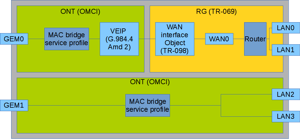
Figure 42 – Services configuration in ONT and RG domains
Figure 42 shows two services (each with a corresponding GEM port on the ONT side), with one of them being routed and using both the OMCI and RG management domains and the other one being bridged and using only OMCI for configuration. Access node configuration includes configuration of bridge interfaces (green areas in the figure) and distribution of LAN ports between the management domains.
The bridge parameter of the cross-connect profile is responsible for association of a service with a management domain. Being set, the bridge parameter creates a bridged service (the bridge group parameter is the bridge number in this case). When no bridge is set, a routed service is created (there is only one bridge associated with RG; it has a special bridge number – 0).
Mixed configuration
Consider an example of ONT configuration, which simultaneously uses both management domains. Port numbers and the internal structure are shown in Figure 42.
Step 1. Create a VLAN for services on the switch. VLAN configuration is described in detail in VLAN configuration:
ma4000(config)# vlan 20
ma4000(vlan-20)# tagged front-port 1/0
ma4000(vlan-20)# tagged slot-channel 0
ma4000(vlan-20)# tagged plc-pon-port 0/0-7
ma4000(vlan-20)# tagged plc-slot-channel 0/0
ma4000(vlan-20)# exit
ma4000(config)# vlan 30
ma4000(vlan-30)# tagged front-port 1/0
ma4000(vlan-30)# tagged slot-channel 0
ma4000(vlan-30)# tagged plc-pon-port 0/0-7
ma4000(vlan-30)# tagged plc-slot-channel 0/0
Step 2. Specify 3 as a service model value corresponding to the VLAN for Service model by using the gpon olt model command:
ma4000# configure terminal
ma4000(config)# gpon olt model 3
Step 3. Define cross-connect profiles for services:
ma4000(config)# profile cross-connect RG-service
ma4000(config-cross-connect)("RG-service")# exit
ma4000(config)# profile cross-connect OMCI-service
ma4000(config-cross-connect)("OMCI-service")#
ma4000(config-cross-connect)("OMCI-service")# exit
Step 4. Define the dba profile. DBA parameters are not important for the purposes of this section. Thus, we will not configure DBA parameters, just use the default values. We will also assign one profile to both services that means that upstream services will operate with one T-CONT. DBA configuration is described in detail in DBA configuration:
ma4000(config)# profile dba basic
ma4000(config-dba)("basic")# exit
Step 5. Create ports profile:
ma4000(config)# profile ports 2RG-2OMCI
ma4000(config-ports)("2RG-2OMCI")# exit
Step 6. Configure routed service. Use one VLAN 20 on both the OLT and ONT sides. Specify a routed service by using the no bridge command. Configure a cross-connect profile for the routed service:
ma4000(config)# profile cross-connect RG-service
ma4000(config-cross-connect)("RG-service")# no bridge
ma4000(config-cross-connect)("RG-service")# type general
ma4000(config-cross-connect)("RG-service")# tag-mode single-tagged
ma4000(config-cross-connect)("RG-service")# outer vid 20
ma4000(config-cross-connect)("RG-service")# outer cos unused
ma4000(config-cross-connect)("RG-service")# user vid untagged
ma4000(config-cross-connect)("RG-service")# mac-table-limit unlimited
ma4000(config-cross-connect)("RG-service")# priority 0
Step 7. Configure bridged service. Use one VLAN 30 on both the OLT and ONT sides. Specify a bridged service by using the no bridge command. Set 1 as the OMCI bridge number. Configure a cross-connect profile for the bridged service:
ma4000(config)# profile cross-connect OMCI-service
ma4000(config-cross-connect)("OMCI-service")# bridge
ma4000(config-cross-connect)("OMCI-service")# bridge group 1
ma4000(config-cross-connect)("OMCI-service")# type general
ma4000(config-cross-connect)("OMCI-service")# tag-mode single-tagged
ma4000(config-cross-connect)("OMCI-service")# outer vid 30
ma4000(config-cross-connect)("OMCI-service")# outer cos unused
ma4000(config-cross-connect)("OMCI-service")# user vid untagged
ma4000(config-cross-connect)("OMCI-service")# mac-table-limit unlimited
ma4000(config-cross-connect)("OMCI-service")# priority 1
You specified different priority queue values for the services. The routed service will have a higher priority than the bridged service as they work with one T-CONT.
Step 8. Configure ports profile. According to Figure 42, we need to associate the first two LAN ports with the RG management domain, while the other two should be associated with the OMCI domain and bound to bridge 1:
ma4000(config)# profile ports 2RG-2OMCI
ma4000(config-ports)("2RG-2OMCI")# port 0 bridge group 0
ma4000(config-ports)("2RG-2OMCI")# port 1 bridge group 0
ma4000(config-ports)("2RG-2OMCI")# port 2 bridge group 1
ma4000(config-ports)("2RG-2OMCI")# port 3 bridge group 1
Step 9. Set the ONT configuration. Create an ONT configuration. ONT management is described in details in Section ONT configuration:
ma4000(config)# interface ont 0/0/0
ma4000(config)(if-ont-0/0/0)#
Step 10. Assign created profiles. Assign the cross-connect RG-service profile to service 0 and the cross-connect OMCI-service profile to service 1:
ma4000(config)# interface ont 0/0/0
ma4000(config)(if-ont-0/0/0)# serial ELTX10203040
ma4000(config)(if-ont-0/0/0)# service 0 profile cross-connect RG-service
ma4000(config)(if-ont-0/0/0)# service 0 profile dba basic
ma4000(config)(if-ont-0/0/0)# service 1 profile cross-connect OMCI-service
ma4000(config)(if-ont-0/0/0)# service 1 profile dba basic
ma4000(config)(if-ont-0/0/0)# profile ports 2RG-2OMCI
Step 11. Use the show interface ont <id> configuration command to check the created configuration:
ma4000(config)(if-ont-0/0/0)# do show interface ont 0/0/0 configuration

-----------------------------------
[ONT0/0/0] configuration
-----------------------------------

    Description:                                       ''
    Status:                                            UP
    Serial:                                            ELTX10203040
…

   Service [0]:
        Profile cross connect:                         RG-service        ONT Profile Cross Connect 6
        Profile dba:                                   basic             ONT Profile DBA 6
        Custom vlan:                                   200
        Custom CoS:                                    unused
    Service [1]:
        Profile cross connect:                         OMCI-service      ONT Profile Cross Connect 7
        Profile dba:                                   basic             ONT Profile DBA 6
        Custom vlan:                                   200
        Custom CoS:                                    unused
…
    Profile shaping:                                   shaping-00        ONT Profile Shaping 0
    Profile ports:                                     2RG-2OMCI         ONT Profile Ports 2
    Profile management:                                management-00     ONT Profile Management 0
    Profile scripting:                                 unassigned
    Custom model:                                      none
    Template:                                          unassigned
	Pppoe sessions unlimited:                          false
    Ports:
        Port [0]:
            shutdown:                                  false
            PoE:
                Enable:                                false
                Pse class control:                     0
                Power priority:                        high
        Port [1]:
            shutdown:                                  false
            PoE:
                Enable:                                false
                Pse class control:                     0
                Power priority:                        high
        Port [2]:
            shutdown:                                  false
            PoE:
                Enable:                                false
                Pse class control:                     0
                Power priority:                        high
        Port [3]:
            shutdown:                                  false
            PoE:
                Enable:                                false
                Pse class control:                     0
                Power priority:                        high
Step 12. Apply changes by the commit command:
ma4000(config)(if-ont-0/0/0)# do commit
As a result, you will have the mixed configuration of the ONT. One of the services is managed completely by the OMCI domain (the bridged service), LAN2 and LAN3 ports on the ONT are connected as bridges. The second service is managed by both OMCI and RG (the routed service; the RG domain can be configured, for instance, through the WEB interface on the ONT). LAN0 and LAN1 ports are connected to RG ONT.
High Speed Internet configuration
Configuration of the High Speed Internet (HSI) service does not have any peculiarities and can be easily performed as described in Section ONT configuration.
Multicast configuration
Introduction
This section describes peculiarities of multicast service configuration for model 1 and model 3.
Model 1 Multicast configuration
This section provides an example of multicast service configuration for model 1.
An STB, which works in VLAN 14, is connected to an ONT port in this example. Upstream IGMP packets arrive to VLAN 14 though a GEM port and the OLT changes VLAN 14 to subscriber's VLAN 200. As we have a multicast server in VLAN 98 in our example, we need to configure a proxy on the switch to translate IGMP packets from VLAN 200 to VLAN 98 (for more information, see VLAN configuration). The multicast service comes downstream to the ONT port in VLAN 98 and changes to VLAN 14.
For more information on general configuration principles of data communication channels, see Section ONT configuration.
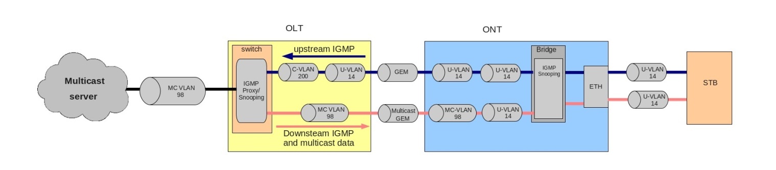
Figure 43 – Model 1 Multicast
Step 1. Specify the ONT serial number in the configuration:
ma4000# configure terminal
ma4000(config)# interface ont 0/0/0
ma4000(config)(if-ont-0/0/0)# serial ELTX01234567
ma4000(config)(if-ont-0/0/0)# exit
Step 2. Assign a service model:
ma4000(config)# gpon olt model 1
Step 3. Create an UsIGMP cross-connect profile to configure the service, which will be used to send IGMP requests upstream. Configure a bridged service and specify the bridged group (it equals 1 in our example) the ONT port will be associated with; specify U-VLAN 14:
ma4000(config)# profile cross-connect UsIGMP
ma4000(config-cross-connect)("UsIGMP")# bridge
ma4000(config-cross-connect)("UsIGMP")# bridge group 1
ma4000(config-cross-connect)("UsIGMP")# user vid 14
ma4000(config-cross-connect)("UsIGMP")# do show profile cross-connect UsIGMP
    Name:                                              'UsIGMP'
    Description:                                       'ONT Profile Cross Connect 8'
    Model:                                             ont
    Bridge group:                                      1
    Tag mode:                                          single-tagged
    Outer vid:                                         1
    Outer cos:                                         unused
    Inner vid:                                         -
    U vid:                                             14
    U cos:                                             unused
    Mac table entry limit:                             unlimited
    Type:                                              general
    Iphost eid:                                        0
    Priority queue:                                    0
Step 4. Bind bridge group to ONT port. To do this, create a ports profile and assign value 1 to the bridge group parameter for the LAN1 port:
ma4000(config)# profile ports Ports1
ma4000(config-ports)("Ports1")# port 1 bridge group 1
Step 5. Enable multicasting and configure VLAN replacement rules for the ONT port:
ma4000(config-ports)("Ports1")# port 1 multicast
ma4000(config-ports)("Ports1")# port 1 igmp downstream vid 14
ma4000(config-ports)("Ports1")# port 1 igmp downstream tag-control replace-vid
ma4000(config-ports)("Ports1")# port 1 igmp upstream vid 14
ma4000(config-ports)("Ports1")# port 1 igmp upstream tag-control replace-vid
Step 6. You also need to configure VLAN 98 multicasting and specify the group range:
ma4000(config-ports)("Ports1")# igmp multicast dynamic-entry 0 vid 98
ma4000(config-ports)("Ports1")# igmp multicast dynamic-entry 0 group 224.0.0.0 239.255.255.255
ma4000(config-ports)("Ports1")# do show profile ports Ports1
    Name:                                              'Ports1'
    Description:                                       'ONT Profile Ports 1'
    Igmp settings:
        Version:                                       3
        Mode:                                          snooping
        Immediate leave:                               false
        Robustness:                                    2
        Querier ip:                                    0.0.0.0
        Query interval:                                125
        Query response interval:                       100
        Last member query interval:                    10
        Multicast dynamic entry [0]:
            Vlan id:                                   98
            First group ip:                            224.0.0.0
            Last group ip:                             239.255.255.255
…
    Port [1]:
        Bridge group:                                  1
        Spanning tree for bridge group:                false
        Multicast enable:                              true
        Multicast port settings:
            Upstream igmp vid:                         14
            Upstream igmp prio:                        0
            Upstream igmp tag control:                 replace vid
            Downstream multicast vid:                  14
            Downstream multicast prio:                 0
            Downstream multicast tag control:          replace vid
            Max groups:                                0
            Max multicast bandwidth:                   0
        Shaper downstream:
            Enable:                                    false
            Commited rate:                             1000000
        Shaper upstream:
            Enable:                                    false
            Commited rate:                             1000000
            Commited rate:                             1000000
…
Step 7. Assign the created profiles in the ONT. Configure a custom-cross-connect profile, specify C-VLAN 200, and apply the configuration:
ma4000(config)# interface ont 0/0/0
ma4000(config)(if-ont-0/0/0)# service 0 profile cross-connect UsIGMP
ma4000(config)(if-ont-0/0/0)# profile ports Ports1
ma4000(config)(if-ont-0/0/0)# service 0 custom cvid 200
ma4000(config)(if-ont-0/0/0)# do commit
Step 8. Add VLAN 98 and VLAN 200. Enable IGMP snooping:
ma4000# configure terminal
ma4000(config)# vlan 200
ma4000(vlan-200)# tagged front-port 1/0
ma4000(vlan-200)# tagged slot-channel 0
ma4000(vlan-200)# tagged plc-pon-port 0/0-7
ma4000(vlan-200)# tagged plc-slot-channel 0/0
ma4000(vlan-200)# ip igmp snooping enable
ma4000(vlan-200)# exit
ma4000(config)# vlan 98
ma4000(vlan-98)# tagged front-port 1/0
ma4000(vlan-98)# tagged slot-channel 0
ma4000(vlan-98)# tagged plc-pon-port 0/0-7
ma4000(vlan-98)# tagged plc-slot-channel 0/0
ma4000(vlan-98)# ip igmp snooping enable
ma4000(vlan-98)# exit
Step 9. Configure IGMP proxy for IGMP packets transmission from VLAN 200 to VLAN 98. Apply the configuration:
ma4000(config)# ip igmp proxy report enable
ma4000(config)# ip igmp proxy report range 224.0.0.0 239.255.255.255 from 200 to 98
ma4000(config)# ip igmp snooping enable
ma4000(config)# do commit
Model 3 Multicast configuration
Consider configuration of a multicast service for Model 3.
In our example, the multicast server operates in VLAN 98. An STB, which works in VLAN 14, is connected to an ONT port. Upstream IGMP packets pass through VLAN 14 to ONT, where VLAN 14 is replaced by the service VLAN 98. The data goes through the GEM port upwards. The multicast service comes downstream to the ONT port in VLAN 98 and changes to VLAN 14. For more information on general configuration principles of data communication channels, see Section ONT configuration.

Figure 44 – Model 3 Multicast
Step 1. Specify the ONT serial number in the configuration:
ma4000# configure terminal
ma4000(config)# interface ont 0/0/0
ma4000(config)(if-ont-0/0/0)# serial ELTX01234567
ma4000(config)(if-ont-0/0/0)# exit
Step 2. Assign a service model:
ma4000(config)# gpon olt model 3
Step 3. Create an UsIGMP cross-connect profile to transfer IGMP requests upstream. Configure a bridged service and specify the bridged group (it equals 1 in our example) the ONT port will be associated with. Specify U-VLAN 14 and S-VLAN 98:
ma4000(config)# profile cross-connect UsIGMP
ma4000(config-cross-connect)("UsIGMP")# bridge
ma4000(config-cross-connect)("UsIGMP")# bridge group 1
ma4000(config-cross-connect)("UsIGMP")# outer vid 98
ma4000(config-cross-connect)("UsIGMP")# user vid 14
ma4000(config-cross-connect)("UsIGMP")# do show profile cross-connect UsIGMP
    Name:                                              'UsIGMP'
    Description:                                       'ONT Profile Cross Connect 8'
    Model:                                             ont
    Bridge group:                                      1
    Tag mode:                                          single-tagged
    Outer vid:                                         98
    Outer cos:                                         unused
    Inner vid:                                         -
    U vid:                                             14
    U cos:                                             unused
    Mac table entry limit:                             unlimited
    Type:                                              general
    Iphost eid:                                        0
    Priority queue:                                    0
Step 4. Bind bridge group to ONT port. To do this, create a ports profile and assign value 1 to the bridge group parameter for the LAN1 port:
ma4000(config)# profile ports Ports1
ma4000(config-ports)("Ports1")# port 1 bridge group 1
Step 5. Enable multicasting and configure VLAN replacement rules for the ONT port:
ma4000(config-ports)("Ports1")# port 1 multicast
ma4000(config-ports)("Ports1")# port 1 igmp downstream vid 14
ma4000(config-ports)("Ports1")# port 1 igmp downstream tag-control replace-vid
ma4000(config-ports)("Ports1")# port 1 igmp upstream vid 98
ma4000(config-ports)("Ports1")# port 1 igmp upstream tag-control replace-vid
Step 6. You also need to configure VLAN 98 multicasting and specify the group range:
ma4000(config-ports)("Ports1")# igmp multicast dynamic-entry 0 vid 98
ma4000(config-ports)("Ports1")# igmp multicast dynamic-entry 0 group 224.0.0.0 239.255.255.255
ma4000(config-ports)("Ports1")# do show profile ports Ports1
    Name:                                              'Ports1'
    Description:                                       'ONT Profile Ports 1'
    Igmp settings:
        Version:                                       3
        Mode:                                          snooping
        Immediate leave:                               false
        Robustness:                                    2
        Querier ip:                                    0.0.0.0
        Query interval:                                125
        Query response interval:                       100
        Last member query interval:                    10
        Multicast dynamic entry [0]:
            Vlan id:                                   98
            First group ip:                            224.0.0.0
            Last group ip:                             239.255.255.255
…
    Port [1]:
        Bridge group:                                  1
        Spanning tree for bridge group:                false
        Multicast enable:                              true
        Multicast port settings:
            Upstream igmp vid:                         98
            Upstream igmp prio:                        0
            Upstream igmp tag control:                 replace vid
            Downstream multicast vid:                  14
            Downstream multicast prio:                 0
            Downstream multicast tag control:          replace vid
            Max groups:                                0
            Max multicast bandwidth:                   0
        Shaper downstream:
            Enable:                                    false
            Commited rate:                             1000000
        Shaper upstream:
            Enable:                                    false
            Commited rate:                             1000000
…
Step 7. Assign the created profiles in the ONT and apply the configuration:
ma4000(config)# interface ont 0/0/0
ma4000(config)(if-ont-0/0/0)# service 0 profile cross-connect UsIGMP
ma4000(config)(if-ont-0/0/0)# profile ports Ports1
ma4000(config)(if-ont-0/0/0)# do commit
Step 8. Add VLAN 98 and enable IGMP snooping:
ma4000(config)# vlan 98
ma4000(vlan-98)# tagged front-port 1/0
ma4000(vlan-98)# tagged slot-channel 0
ma4000(vlan-98)# tagged plc-pon-port 0/0-7
ma4000(vlan-98)# tagged plc-slot-channel 0/0
ma4000(vlan-98)# ip igmp snooping enable
ma4000(vlan-98)# exit
ma4000(config)# ip igmp snooping enable
ma4000(config)# do commit
VoIP configuration
VoIP service is configured in a usual way for routed services. The procedure is described in detail in ONT configuration. All the general steps of service configuration are applied to VoIP as well.
MA4000-PX supports telephony configuring via OMCI (ONT made by ELTEX are not supported). The procedure is described in details in Appendix A. VoIP configuration section.
TR-069 management configuration
Introduction
This section describes configuration of a data communication channel for the CPE management service via the TR-069 protocol.
An ONT management channel can be established in one of the two modes: Inband and OutOfBand. Inband is the preferred mode as it is simpler. Contact your ONT vendor for information about operation capabilities of both modes.
ONT management via TR-069 is a special service. All general steps of service configuration apply to TR-069 management. Operator's actions required for services configuration are described in detail in ONT configuration.
As opposed to other services, the management service requires the management type in the cross-connect profile. You also need to specify the Iphost eid parameter. As a rule, it should be equal to 0.
Configuration of a TR-069 Inband management
This mode is characterised by its simple implementation. Management traffic goes through the same bridge as user traffic. Figure 45 shows a part of the OMCI layout. Arrows show the traffic flow.

Figure 45 – TR-069 Inband management channel
Step 1. Set the management type in the cross-connect profile:
ma4000(config)# profile cross-connect TR069
ma4000(config-cross-connect)("TR069")# type management
ma4000(config-cross-connect)("TR069")# no bridge
Step 2. Set the IP Host identifier to 0:
ma4000(config-cross-connect)("TR069")# iphost eid 0
Step 3. Check the changes made:
ma4000(config-cross-connect)("TR069")# do show profile cross-connect TR069
    Name:                                              'TR069'
    Description:                                       'ONT Profile Cross Connect 10'
    Model:                                             ont-rg
    Bridge group:                                      -
    Tag mode:                                          single-tagged
    Outer vid:                                         1
    Outer cos:                                         unused
    Inner vid:                                         -
    U vid:                                             untagged
    U cos:                                             unused
    Mac table entry limit:                             unlimited
    Type:                                              management
    Iphost eid:                                        0
    Priority queue:                                    0
Step 4. Apply the changes by using the commit command:
ma4000(config-cross-connect)("TR069")# do commit
Configuration of a TR-069 OOB management channel
Not all ONT vendors support creation of Inband management channels via TR-069. To solve this, a capability to create an OutOfBand management channel was developed as an alternative. The main peculiarity of the mode is that is uses a separate bridge for management. Figure 46 shows a part of the OMCI layout. Arrows show the traffic flow.
Step 1. Set the management type in the cross-connect profile:
ma4000(config)# profile cross-connect TR069
ma4000(config-cross-connect)("TR069")# type management
Step 2. Set the ont model of the cross-connect profile. Specify a separate bridge group:
ma4000(config-cross-connect)("TR069")# bridge
ma4000(config-cross-connect)("TR069")# bridge group 20
Step 3. Set the IP Host identifier to 0:
ma4000(config-cross-connect)("TR069")# iphost eid 0
Step 4. Check the changes by using the show command:
ma4000(config-cross-connect)("TR069")# do show profile cross-connect TR069
    Name:                                              'TR069'
    Description:                                       'ONT Profile Cross Connect 10'
    Model:                                             ont
    Bridge group:                                      20
    Tag mode:                                          single-tagged
    Outer vid:                                         1
    Outer cos:                                         unused
    Inner vid:                                         -
    U vid:                                             untagged
    U cos:                                             unused
    Mac table entry limit:                             unlimited
    Type:                                              management
    Iphost eid:                                        0
    Priority queue:                                    0
Step 5. Apply the changes by using the commit command:
ma4000(config-cross-connect)("TR069")# do commit

Figure 46 – TR-069 OutOfband management channel
TR-069 client parameters configuration
To configure TR-069 client parameters, use the management profile:
ma4000# show profile management management-00
    Name:                                              'management-00'
    Description:                                       'ONT Profile Management 0'
    Enable omci configuration:                         true
    Url:                                               ''
    Username:                                          ''
    Password:                                          ''
When the DHCP server transmits the TR-069 parameters via option 43, there is no need to transfer them via OMCI. Disable this phase with the no omci-configuration command.
Otherwise, specify TR-069 client parameters explicitly.
Step 1. Enable TR-069 configuration:
ma4000# configure terminal
ma4000(config)# profile management management-00
ma4000(config-management)("management-00")# omci-configuration
Step 2. Set the connection parameters:
ma4000(config-management)("management-00")# url http://acs-tele.com:9595/acs
ma4000(config-management)("management-00")# username acs
ma4000(config-management)("management-00")# password acsacs
Step 3. Check the changes made:
ma4000(config-management)("management-00")# do show profile management management-00
    Name:                                              'management-00'
    Description:                                       'ONT Profile Management 0'
    Enable omci configuration:                         true
    Url:                                               'http://acs-tele.com:9595/acs'
    Username:                                          'acs'
    Password:                                          'acsacs'
Step 4. Apply the changes by using the commit command:
ma4000(config-management)("management-00")# do commit
ONT configuration templates
Introduction
It is not always convenient, especially for large-scale operators, to build ONT configuration from separate profiles for each subscriber. This process is painstaking and risky in a certain sense, as it is highly prone to operator error.
As a rule, such companies employ at least one service plan with pre-defined ONT profiles. This section describes ONT templates, an effective solution to simplify the work of subscriber service specialists.
The essence of configuration templates is simple. Network administrator prepares required quantity of templates for the quantity of service plans. Configuration template contains detailed profile list and a set of ONT parameters. Subscriber service specialist or OSS/BSS system assigns the template to an ONT and identifies additional configuration parameters if necessary. As a rule, configuration assignment is performed in one click or by using one command.
Preparing ONT configuration template
Step 1. Define an ONT configuration template:
ma4000(config)# template HSI-100-CaTV
ma4000(ont-template)("HSI-100-CaTV")#
Step 2. Set the ONT configuration. Template configuration does not have any peculiarities and exactly follows the ONT configuration process described in ONT configuration:
ma4000(ont-template)("HSI-100-CaTV")# service 0 profile dba AllServices
ma4000(ont-template)("HSI-100-CaTV")# service 0 profile cross-connect Service1
ma4000(ont-template)("HSI-100-CaTV")# service 1 profile dba AllServices
ma4000(ont-template)("HSI-100-CaTV")# service 1 profile cross-connect Service2
ma4000(ont-template)("HSI-100-CaTV")# profile ports Ports1
…
Step 3. Disable all configuration parameters that should be specified explicitly for the ONT with the undefine command, if necessary:
ma4000(ont-template)("HSI-100-CaTV")# undefine rf-port-state
…
Step 4. Apply the changes:
ma4000(ont-template)("HSI-100-CaTV")# do commit
ONT configuration template assignment
Step 1. Switch to the ONT view. You can use a range of ONT IDs for group operations if necessary:
ma4000(config)# interface ont 0/0/0-10
ma4000(config)(if-ont-0/0/0-10)#
Step 2. Assign an ONT configuration template by using the template command:
ma4000(config)(if-ont-0/0/0-10)# template HSI-100-CaTV
Step 3. Define individual ONT parameters not specified in the template if necessary:
ma4000(config)(if-ont-0/0/0-10)# rf-port-state enabled
Step 4. Apply the changes:
ma4000(config)(if-ont-0/0/0-10)# do commit
ONT configuration preview with templates
You can view the ONT configuration using the same command: show interface ont <id> configuration. You can distinguish the template parameters from the general ones by [T](Template) markers. In this example, Rf port state is the only general parameter:
ma4000(config)(if-ont-0/0/0-10)# do show interface ont 0/0/0 configuration

-----------------------------------
[ONT0/0/0] configuration
-----------------------------------

    Description:                                       ''
    Enabled:                                           true
    Serial:                                            ELTX01234567
    Password:                                          '0000000000'
[T] Fec up:                                            false
[T] Downstream broadcast:                              true
[T] Ber interval:                                      100000
[T] Ber update period:                                 60
    Rf port state:                                     enabled
[T] Omci error tolerant:                               false
    Service [0]:
[T]     Profile cross connect:                         Service1          ONT Profile Cross Connect 4
[T]     Profile dba:                                   AllServices       ONT Profile DBA 2
        Custom vlan:                                   200
        Custom CoS:                                    unused
    Service [1]:
[T]     Profile cross connect:                         Service2          ONT Profile Cross Connect 3
[T]     Profile dba:                                   AllServices       ONT Profile DBA 2
        Custom vlan:                                   200
        Custom CoS:                                    unused
[T] Profile shaping:                                   shaping-00        ONT Profile Shaping 0
[T] Profile ports:                                     Ports1            ONT Profile Ports 1
[T] Profile management:                                management-00     ONT Profile Management 0
[T] Profile scripting:                                 unassigned
    Custom model:                                      none
    Template:                                          HSI-100-CaTV      ONT Template 1
	Pppoe sessions unlimited:                          false
	Ports:
        Port [0]:
            shutdown:                                  false
            PoE:
                Enable:                                false
                Pse class control:                     0
                Power priority:                        high
        Port [1]:
            shutdown:                                  false
            PoE:
                Enable:                                false
                Pse class control:                     0
                Power priority:                        high
        Port [2]:
            shutdown:                                  false
            PoE:
                Enable:                                false
                Pse class control:                     0
                Power priority:                        high
        Port [3]:
            shutdown:                                  false
            PoE:
                Enable:                                false
                Pse class control:                     0
                Power priority:                        high
ONT licensing
Introduction
By default, OLT supports only Eltex ONTs operation. To enable any third-party ONTs, OLT requires a license. To purchase the license, contact Eltex Marketing Department.
If a third-party ONT is connected to OLT without a license, the following entry will be made in the log file:
2017-01-18 05:11:39 pmchal: error: [ONT2/0] License is not valid, configuration will not continue
Loading a license file to OLT
A license is a text file of the following format:
{
	"version":	"<VER>",
	"type":	"all",
	"count":	"<count>",
	"sn":	"<SN>",
	"mac":	"<MAC>",
	"sign":	"<hash>"
}
Where:
- VER – license file version number;
- count – number of third-party ONTs that can run on OLT;
- SN – LTP serial number;
- MAC – LTP MAC address;
- hash – license file digital signature.
There are two ways to load a license to OLT:
- Use the copy command:
ma4000# copy tftp://<IP>/<PATH> fs://license
    Download file from TFTP-server..
License successfully installed. Please reboot device for changes to make effect
Where:
- IP – TFTP server IP address;
- PATH – license file path on TFTP server.
2. Use CLI:
ma4000# license set """<license>"""
License successfully installed. Please reboot device for changes to make effect
Where:
- license – full content of the license file including curly brackets.
To view information about the license on the device, use the show command:
ma4000#  show license
Active license information:
    License valid:               yes
    Version:                     1.1
    Carrier:                     Eltex Enterprise LLC
    Licensed vendor:             all
    Licensed ONT count:          unlimited
    Licensed ONT online:         2
    SN:
                                 OL02000000
  Mac:
                                 A8:F9:4B:00:00:00
The license file remains after device reload, firmware update, and configuration load. If OLT is reset to factory settings, the license is also deleted.
ONT ports management
Introduction
This chapter describes management of Ethernet ports via OMCI. You may switch Ethernet ports on and off on a connected ONT, manage and control PoE as power source .
If PoE ports are suported on ONTs you may manage ports:
- enable/disable PoE on ports;
- control power class;
- priority management.
All the attributes mentioned above are transmitted via OMCI (ITU-T G.988 ME 11 "PPTP Ethernet UNI").
Managing ONT Ethernet ports
ONT Ethernet ports managment involves enabling/disabling of these ports and implements with the help of [no] port <port number> shutdown command, where <port number> is the number of needed port "0–3".
Step 1. For disabling an Ethernet port use the following commands:
MA4000(config)# interface ont 10/4/0
MA4000(config)(if-ont-10/4/0)# port 0 shutdown
MA4000(config)(if-ont-10/4/0)# do commit
MA4000(config)(if-ont-10/4/0)# do confirm
Step 2. Make sure the changes has been applied:
MA4000(config)(if-ont-10/4/0)# do show interface ont 10/4/0 configuration
...
    Pppoe sessions unlimited:                          false
    Ports:
        Port [0]:
            shutdown:                                  true
            PoE:
                Enable:                                false
                Pse class control:                     0
                Power priority:                        high
        Port [1]:
            shutdown:                                  false
            PoE:
                Enable:                                false
                Pse class control:                     0
                Power priority:                        high
        Port [2]:
            shutdown:                                  false
            PoE:
                Enable:                                false
                Pse class control:                     0
                Power priority:                        high
        Port [3]:
            shutdown:                                  false
            PoE:
                Enable:                                false
                Pse class control:                     0
                Power priority:                        high
Step 3. To enable an Ethernet port do the following:
MA4000(config)# interface ont 10/4/0
MA4000(config)(if-ont-10/4/0)# no port 0 shutdown
MA4000(config)(if-ont-10/4/0)# do commit
MA4000(config)(if-ont-10/4/0)# do confirm
Manading PoE on ONT ports
Managing PoE on ONT ports is implemented by using port <port number> poe enable pse-class-control <class> power-priority <level> command, where
- <port number> — the number of port "0-3";
- <class> — power class "0-5";
- <level> — priority level "critical/high/low".
Enabling PoE on ONT ports
For enabling Po Eon ONT ports, use the following commands:
MA4000(config)(if-ont-10/4/0)# port 0 poe enable
MA4000(config)(if-ont-10/4/0)# do commit
MA4000(config)(if-ont-10/4/0)# do confirm
Power class control
This attribute might be used for limiting of power class. Available values:
- 0 — power supply is enabled and has a default power level for this port;
- 1 — power supply is enabled on the level of power class 0;
- 2 — power supply is enabled on the level of power class 1;
- 3 — power supply is enabled on the level of power class 2;
- 4 — power supply is enabled on the level of power class 3;
- 5 — power supply is enabled on the level of power class 4.
For changing the power class of PoE on the ports, use the following commands:
MA4000(config)(if-ont-10/4/0)# port 0 poe pse-class-control 0
MA4000(config)(if-ont-10/4/0)# do commit
MA4000(config)(if-ont-10/4/0)# do confirm
Managing PoE priority
This attribute manages port priority according to powewr management algorythm. The priority set by this attribute might be used by management system which prevents electrical current overloads. To avoid overloads, the system will disable ONTs LAN ports starting with the ports with the lowest PoE priority.
Available values:
- critical;
- high (default value);
- low.
To change the PoE priority in the ONT ports, do the following:
MA4000(config)(if-ont-10/4/0)# port 0 poe power-priority low
MA4000(config)(if-ont-10/4/0)# do commit
MA4000(config)(if-ont-10/4/0)# do confirm
General information
Viewing current access node firmware version
To view information on the current version of access node firmware, use the show firmware command:
ma4000# show firmware

   Firmware status:
   ~~~~~~~~~~~~~~~~
Unit   Image   Running   Boot          Version               Date
----   -----   -------   -----------   -------------------   ---------------------
1      0       No                      3 24 0 448 44346      26-Nov-2015 08:26:00
1      1       Yes       *             3 24 0 451 44381      26-Nov-2015 12:06:47
2      0       No                      3 24 0 448 44346      26-Nov-2015 08:26:00
2      1       Yes       *             3 24 0 451 44381      26-Nov-2015 12:06:47

"*" designates that the image was selected for the next boot
View information on access node
To view information about PP4X modules, use the show system information command. PP4X module number shall be specified as a parameter.
ma4000# show system information 1
System information (1):
Uptime (d:h:m:s): 3:7:33:38
CPU load (1/5/15 minutes): 0.31/1.29/1.41
RAM (total/free), Mbytes: 498/25
Partition '/' (total/free), Mbytes: 57/21
Partition '/mnt/tools' (total/free), Mbytes: 1024/932
Partition '/mnt/config' (total/free), Mbytes: 64/59
Partition '/mnt/log' (total/free), Mbytes: 128/117
Temperature (SFP): 22C
Temperature (CPU): 32C
Temperature (Switch) : 44C
Firmware version: 3.24.0.451 r44381 12:06:40 26/11/2015
Linux version: Linux version 2.6.22.18 (jenkins@xpon.eltex.loc) (gcc version 4.3.2 (sdk3.2rc1-ct-ng-1.4.1) ) #1 Thu Nov 26 18:21:10 NOVT 2015
MAC address: a8:f9:4b:81:82:20
Serial number: OL02000032
To view information about the chassis, use the show system environment command:
ma4000# show system environment
MFC board status: ok
MFC board version: 0x2
MFC firmware:
Status: 0x00 (ok)
Version: 8 2 1 1 5 05/11/2013
Timestamp (UTC): 05-Nov-2013 12:19:22
Fan configured speed, %: 56
Fan minimum speed, %: 15
Fan speed levels, %: 15 25 36 46 57 68 78 89 100
Fan0 Fan1 Fan2
Status: ok ok ok
RPM: 3678 3624 3582
Feeder1 Feeder2
Status: ok REVERSED
Current, A: 4.25 0.00
Voltage, V: -54.18 1.73
Shelf voltage, V: -53.48
Feeder1 Feeder2
Status: REVERSED ok
Current, A: 0.00 1.00
Voltage, V: 1.92 -53.69
Shelf voltage, V: -54.35
Viewing interface modules status
To view information on interface modules, use the show shelf command:
ma4000# show shelf Shelf status ~~~~~~~~~~~~ Slot # Configured Type Detected Type Version Serial # Link State Slot State ------ --------------- ------------- ------------ ----------- ---------- ------------ 0 plc8 plc8 3.24.0.451 OL04001750 up Operational 1 none none 0.0.0.0 down Absent 2 none none 0.0.0.0 down Absent 3 none none 0.0.0.0 down Absent 4 none none 0.0.0.0 down Absent 5 none none 0.0.0.0 down Absent 6 none none 0.0.0.0 down Absent 7 none none 0.0.0.0 down Absent 8 none none 0.0.0.0 down Absent 9 none none 0.0.0.0 down Absent 10 none none 0.0.0.0 down Absent 11 none none 0.0.0.0 down Absent 12 none none 0.0.0.0 down Absent 13 none none 0.0.0.0 down Absent 14 none none 0.0.0.0 down Absent 15 none none 0.0.0.0 down Absent
Viewing access node uptime
To view access node operating time, use the show uptime command.
ma4000# show uptime up 3 days, 7:35
Checking network connection
To check network connection, use the ping command. As a parameter, pass the IP address of the node to be checked.
ma4000# ping 192.168.1.254 PING 192.168.1.254 (192.168.1.254): 56 data bytes 64 bytes from 192.168.1.254: seq=0 ttl=64 time=0.422 ms 64 bytes from 192.168.1.254: seq=1 ttl=64 time=0.426 ms 64 bytes from 192.168.1.254: seq=2 ttl=64 time=0.360 ms 64 bytes from 192.168.1.254: seq=3 ttl=64 time=0.397 ms 64 bytes from 192.168.1.254: seq=4 ttl=64 time=0.404 ms --- 192.168.1.254 ping statistics --- 5 packets transmitted, 5 packets received, 0\% packet loss round-trip min/avg/max = 0.360/0.401/0.426 ms
Access node operation log
To view a list of logs, use the show log command:
ma4000# show log Log files ~~~~~~~~~ ## Name Size in bytes Date of last modification ---- -------------------- ---------------- ------------------------- 1 daemon 450 Thu Dec 14 17:55:38 2017 2 pp 126432 Thu Dec 14 17:55:12 2017 3 slot0 65934 Thu Dec 14 17:55:12 2017 ---- -------------------- ---------------- ------------------------- Total files: 2
Table 24 – Operation logs purpose
Name | Description |
|---|---|
daemon | Log messages of MA4000 auxiliary services get saved in the log |
pp | Log messages of master PP4X module get saved in the log |
pp-other | Log messages of slave PP4X module get saved in the log |
slot | Log messages of definite interface module get saved in the log |
To view operation log, use the show log command. Pass the log name as a parameter.
ma4000# show log pp 2014-09-11 16:58:10 rebootd started 2014-09-11 16:58:10 cli-mgr <main> 2014-09-11 16:58:10 cli-mgr <climgr_initialize> 2014-09-11 16:58:10 cli-mgr <main_loop> 2014-09-11 16:58:10 switch %SWITCH: starting up 2014-09-11 16:58:10 switch %SWITCH: start 2014-09-11 16:58:10 syslog-ng syslog-ng starting up; version='3.2.3' 2014-09-11 16:58:10 switch %STARTUP: init 2014-09-11 16:58:10 switch %STARTUP: Position is left 2014-09-11 16:58:10 switch %STARTUP: ShelfId is 15 2014-09-11 16:58:10 switch %FACTORY: reading factory settings... 2014-09-11 16:58:10 switch %FACTORY: OK 2014-09-11 16:58:10 switch %PARSE-CFG: processing configuration file "/tmp/boot.conf.1"... 2014-09-11 16:58:10 switch %PARSE-CFG: Operation successful. 2014-09-11 16:58:10 switch %PARSE-CFG: Operation successful. 2014-09-11 16:58:10 switch %PARSE-CFG: Operation successful. 2014-09-11 16:58:10 switch %PARSE-CFG: Operation successful. 2014-09-11 16:58:10 switch %PARSE-CFG: Operation successful. 2014-09-11 16:58:10 switch %PARSE-CFG: Operation successful. 2014-09-11 16:58:10 switch %PARSE-CFG: parse config: ...done. 2014-09-11 16:58:11 switch Device[0] ID 0xE00D11AB revision B1 or above ...
The log messages can be filtered. To do this, use the show log <journal> grep command. The command takes a string as a parameter that is used for search in the log. Only the messages containing the string will be displayed on the screen.
ma4000# show log pp grep pp4x 2014-09-11 16:58:57 switch %FIRMWARE: by entering 'firmware pp4x confirm unit 1' command in the CLI. 2014-09-11 16:59:46 switch %FIRMWARE: 'firmware pp4x confirm unit 1' command entered.
Active alarms log
Introduction
The system of logging is built on a central application systemdb, which organizes interfaces to events database (DB). All emerging events both from interface boards and PP4X switch itself are sent into systemdb to be saved in the base.
All events are divided into 2 types: one-time and state changing events. One-time events are saved in the base and generate SNMP trap, if necessary. State changing events imply the following: if the state has changed (e.g., Link Flapping has been found on interface) and this state is normalized, then we will get a new event indicating situation improvement. State changing events, if they are alarms, are to be added into a list of active alarms during registration in the base. If situation gets corrected the alarm will be removed from active alarms.
Alarm generation and registration
An event can get into the system of logging by two methods: it can be generated at PP4X itself, or on one of interface boards in MA4000 basket. All codes of events in the basket are entered into a common list for convenience to promptly get SNMP OID code for any event.
Alarm/Event structure
- Alarm code – code of alarm MA4000, an integer value which can range from 1000 to 7000. PP4X uses a range from 1000 to 3000.
- Time – time of occurrence of alarm of this type. Number in seconds since the beginning of the era.
- Priority – alarm rate. An integer from 0 to 3.
- Text – a text field with description up to 255 characters. The name of alarm as well as auxiliary parameters are always preserved in Text field.
- Params – array of 4 integers specific for every particular alarm or notification.
The Active field will indicate, whether this particular alarm is currently active. The alarm will be active from the time of arriving of the first alarm of this type until arrival of an event for its normalization. E.g.: the state will always be Active for ALARM_LINK_CHANGED after dropping the port unless ALARM_LINK_CHANGED event arrives indicating that the port has recovered again.
Time field – time of occurrence of the event.
Alarms rates
- Critical – Critical, level 0. Basket operation functionality is disturbed.
- Major – High, level 1. Separate basket modules operation is affected.
- Minor – Low, level 2. Non-critical problems in separate modules.
- Notify – Notification, level 3. Not an alarm, informs on the event that occured.
Alarms
Alarms from MA4000_ALARM_SLOT family are generated in case of non-standard situations with interface modules in the basket.
All of them feature the following parameters:
- 0 – slot number
- 1 – device type code
- 2 – device version (hw, major, minor)
3 – build of device version
Name: MA4000_ALARM_SLOT_INVALID
Description: Alarm occurring when board type in a slot does not correspond to basket configuration.
Alarm rate: Major
Name: MA4000_ALARM_SLOT_DOWN
Description: Alarm in case of link (slot-channel) drop towards interface board.
Alarm rate: Critical
Name: MA4000_ALARM_SLOT_ERROR
Description: Alarm in case of error in connection with interface board. May be caused due to board pending.
Alarm rate: Critical
Name: MA4000_ALARM_PP4X_UNIT_LOST
Description: Alarm on unplanned loss of one of PP4X units in a basket.
Alarm rate: Critical
Parameters:
- 0 – number of a missing unit;
- 1 – right or left unit is missing.
Name: MA4000_ALARM_SYNC_DISALLOWED
Description: Alarm when configuration synchronization between PP4X units in a basket is disallowed.
Alarm rate: Critical
Parameters:
- 0 – number of a unit, with which synchronization is disallowed.
Name: MA4000_FAN_CONTROLLER_FAIL
Description: Alarm at fan controller failure.
Alarm rate: Major
Parameters: none.
Name: MA4000_CONFIG_SAVE_FAIL
Description: Alarm at error of PP4X configuration saving to memory.
Alarm rate: Major
Parameters: none.
Name: MA4000_ALARM_LINK_DOWN
Description: Alarm as a result of link drop on PP4X.
Alarm rate: Minor
Parameters:
- 0 – interface idb ID.
Name: MA4000_PORT_CNTR_ERRORS_FOUND
Description: Alarm at revealing errors at PP4X ports.
Alarm rate: Minor
Parameters:
- 0 – idb ID of port, where errors have been detected.
Name: MA4000_FAN_FAIL
Description: Alarm at failure of one of the basket fans.
Alarm rate: Major
Parameters:
- 0 – Number of a failing basket fan.
Alarms normalization
Name: MA4000_ALARM_SLOT_OK
Description: Notification on interface board being in a normal operation state. It clears all other alarms of MA4000_ALARM_SLOT family for this slot.
Alarm rate: Notify
Name: MA4000_ALARM_PP4X_UNIT_LOST_OK
Description: Notification on revealing PP4X unit lost earlier in the basket.
Alarm rate: Notify
Parameters:
- 0 – number of a found unit;
- 1 – right or left unit is found.
Name: MA4000_ALARM_SYNC_DISALLOWED_OK
Description: Notification on allowing configuration synchronization with this unit. It clears alarm MA4000_ALARM_SYNC_DISALLOWED.
Alarm rate: Notify
Parameters:
- 0 – number of a unit, with which synchronization is allowed.
Name: MA4000_FAN_CONTROLLER_FAIL_OK
Description: Notification on restoring serviceability of fans controller.It clears alarm MA4000_FAN_CONTROLLER_FAIL. It clears alarm MA4000_FAN_CONTROLLER_FAIL.
Alarm rate: Notify
Parameters: none.
Name: MA4000_ALARM_LINK_UP
Description: Notification on a link appearing at port PP4X. It clears alarm MA4000_ALARM_LINK_DOWN for this port.
Alarm rate: Notify
Parameters:
- 0 – interface idb ID.
Name: MA4000_PORT_CNTR_ERRORS_FREE
Description: Notification on discontinued errors at ports PP4X. It clears alarm MA4000_PORT_CNTR_ERRORS_FOUND.
Alarm rate: Notify
Parameters:
- 0 – idb ID of a port, where no more errors have been detected.
Name: MA4000_FAN_OK
Description: Notification on restoring serviceability of fan. It clears alarm MA4000_FAN_FAIL.
Alarm rate: Notify
Parameters:
- 0 – number of the fan that has restored its operability.
Notifications
Name: MA4000_ALARM_BUFFER_OVERFLOW
Description: A system event occurring in case of alarm queue overflow prior to saving into database.
Alarm rate: Notify
Parameters:
- 0 – number of alarms lost.
Name: MA4000_ALARM_REBOOT_STACK
Description: Notification on entire basket reboot by a command.
Alarm rate: Notify
Parameters: none.
Name: MA4000_ALARM_REBOOT_UNIT
Description: Notification on a separate unit reboot by a command.
Alarm rate: Notify
Parameters:
- 0 – unit number;
- 1 – whether this unit was a master.
Name: MA4000_ALARM_REBOOT_FW_TIMER
Description: Notification on expired confirmation timer after firmware update on PP4X board.
Alarm rate: Notify
Parameters:
- 0 – unit number.
Name: MA4000_ALARM_OMS
Description: Family of notifications on errors at loading/unloading basket configuration through EMS network control system.
Alarm rate: Notify
Parameters:
- 0 – type of command, which reached completion with an error. Configuration downloading or uploading to a remote server;
- 1 – field is constant. Indication that the error has occurred during file operation;
- 2 – code of error, with which operation reached completion.
Name: MA4000_ALARM_OMS_OK
Description: Notification for the EMS network control system on successful downloading/uploading of configuration.
Alarm rate: Notify
Parameters: none.
Name: MA4000_ALARM_FW_UPDATE_FAIL
Description: Notification on the error occurred during updating firmware version and libraries for interface boards in MA4000 basket.
Alarm rate: Notify
Parameters:
- 0 – code of error, with which operation reached completion.
Name: MA4000_ALARM_FW_UPDATE_OK
Description: Notification on successful updating of firmware version and libraries for interface boards in MA4000 basket.
Alarm rate: Notify
Parameters: none.
Name: MA4000_ALARM_FW_CONFIRM_NEEDED
Description: Notification sent to the EMS network control system after updating firmware on PP4X informing on the necessity to perform a confirm command.
Alarm rate: Notify
Parameters:
- 0 – unit number.
Name: MA4000_CONFIG_APPLIED
Description: Notification on PP4X configuration applied.
Alarm rate: Notify
Parameters:
- 0 – current number of configuration revision
Name: MA4000_CONFIG_SAVED
Description: Notification on PP4X configuration saved to flash memory.
Alarm rate: Notify
Parameters: none.
Name: MA4000_CONFIG_RESTORE
Description: Notification on restoration of PP4X configuration or interface board to a previous version. It is a result of a restore command; also appears in case of expiry of a timer set for a confirm command.
Alarm rate: Notify
Parameters:
- 0 – type of device, which has rolled back configuration;
- 1 – slot number (if it is interface board).
Name: MA4000_CSCD_MASTER_CHANGED
Description: Notification on a change of a master in basket.
Alarm rate: Notify
Parameters:
- 0 – number of a new master unit;
- 1 – RH or LH unit became a master.
PP4X monitoring
PP4X resource status
To view the command dispatcher information, use the show cmd-dispatcher command:
ma4000# show cmd-dispatcher
Command Dispatcher memory state:
overload count 0
errors 0
size of element 1192
free 500
length 500
To view the event dispatcher information, use the show evt-dispatcher command:
ma4000# show evt-dispatcher
Command Dispatcher memory state:
overload count 0
errors 0
size of element 992
free 500
length 500
To view the system queue identifiers, use the show queue command:
ma4000# show queue Registered queues: command top manager id 1 event exchange id 2 control exchange id 3 mac sync event descriptors id 4 mac sync control descriptors id 5 cscd event descriptors id 6 cscd command descriptors id 7 config manager event descriptor id 8 config manager command descript id 9 pstate check event descriptors id 10 pstate check control descriptor id 11 sshd event descriptors id 12 telnetd event descriptors id 13 firmware manager event descript id 14 firmware manager command descri id 15 maep cmd descriptors id 16 maep evt descriptors id 17 vlan cmd descriptors id 18 vlan evt descriptors id 19 acsd event descriptors id 20 fan event descriptors id 21 arp event descriptors id 22 arp command descriptors id 23 iprouting event descriptors id 24 iprouting command descriptors id 25 igmp snooping event descriptors id 26 igmp snooping command descripto id 27 snmpag evt descriptors id 28 snmpag cmd descriptors id 29 bonding event descriptors id 30 bonding command descriptors id 31 dhcp client event descriptors id 32 dhcp proxy event descriptors id 33 dhcp proxy command descriptors id 34 dhcp server event descriptors id 35 stp event descriptors id 36 stp command descriptors id 37 lldp event descriptors id 38 lldp command descriptors id 39 sntp client event descriptors id 40 Total queues 40
To view the state of the selected queue, use the show queue command with the queue identifier as a parameter.
ma4000# show queue 0
Queue event top manager :
tx count 17
rx count 17
overload count 0
read from empty count 0
pipe read errors 0
pipe write errors 0
size of element 4
free 500
length 500
MAC table preview
To view the MAC address table, use the show mac pp4 command:
ma4000# show mac pp4 Mac table ~~~~~~~~~ ## VID MAC address Port ------ ---- ----------------- ---------------------------------------- 1 1 00:80:c2:00:00:00 0/CPU 2 1 00:80:c2:00:01:01 slot-channel 0 3 1 a8:f9:4b:88:50:40 slot-channel 0 4 1 00:80:c2:00:01:02 slot-channel 1 5 1 00:80:c2:00:01:03 slot-channel 2 6 1 00:80:c2:00:01:04 slot-channel 3 7 1 00:80:c2:00:01:05 slot-channel 4 8 1 00:80:c2:00:01:06 slot-channel 5 9 1 00:80:c2:00:01:07 slot-channel 6 10 1 00:80:c2:00:01:08 slot-channel 7 11 1 00:80:c2:00:01:09 slot-channel 8 12 1 00:80:c2:00:01:0a slot-channel 9 13 1 00:80:c2:00:01:0b slot-channel 10 14 1 00:80:c2:00:01:0c slot-channel 11 15 1 00:80:c2:00:01:0d slot-channel 12 16 1 00:80:c2:00:01:0e slot-channel 13 17 1 00:80:c2:00:01:0f slot-channel 14 18 1 00:80:c2:00:01:10 slot-channel 15 19 30 a8:f9:4b:82:8b:80 port-channel 1 20 30 a8:f9:4b:82:99:80 port-channel 1 21 30 a8:f9:4b:c0:2a:7a slot-channel 0 22 199 a8:f9:4b:81:85:b0 1/CPU 23 199 a8:f9:4b:81:85:f0 2/CPU 24 199 00:15:17:e4:27:ca port-channel 1 25 199 a8:f9:4b:82:8b:80 port-channel 1 26 199 a8:f9:4b:84:d0:c0 port-channel 1 27 1101 00:15:17:e4:27:ca port-channel 1 28 1101 1c:bd:b9:d8:08:e5 port-channel 1 29 1101 a8:f9:4b:84:f5:40 port-channel 1 30 1200 00:15:17:e4:27:ca port-channel 1 31 1200 00:aa:bb:cc:dd:ee port-channel 1 32 1200 08:60:6e:6d:1a:97 port-channel 1 33 1200 a8:f9:4b:03:53:67 port-channel 1 34 1200 a8:f9:4b:03:54:b1 port-channel 1 35 1200 a8:f9:4b:03:66:2d port-channel 1 36 1200 a8:f9:4b:03:74:08 port-channel 1 37 1200 a8:f9:4b:03:74:a3 port-channel 1 38 1200 a8:f9:4b:2a:58:e7 port-channel 1 39 1200 a8:f9:4b:2a:59:37 port-channel 1 40 1200 a8:f9:4b:2a:59:57 port-channel 1 41 1200 a8:f9:4b:2a:59:8f port-channel 1 42 1200 a8:f9:4b:2a:75:b2 port-channel 1 43 1200 a8:f9:4b:2a:75:e2 port-channel 1 44 1200 a8:f9:4b:2a:76:4a port-channel 1 45 1200 a8:f9:4b:2a:76:8a port-channel 1 46 1200 a8:f9:4b:2a:76:aa port-channel 1 47 1200 a8:f9:4b:2a:76:fa port-channel 1 48 1200 a8:f9:4b:2a:77:8a port-channel 1 49 1200 a8:f9:4b:2a:77:fa port-channel 1 50 1200 a8:f9:4b:2a:78:3a port-channel 1 51 1200 a8:f9:4b:2a:78:42 port-channel 1 52 1200 e0:d9:e3:58:0c:57 port-channel 1 53 1342 1c:bd:b9:d8:08:e5 port-channel 1 54 4094 a8:f9:4b:81:85:b0 1/CPU 55 4094 a8:f9:4b:81:85:f0 2/CPU 55 valid mac entries ma4000# show mac pp4 include vlan 30 Mac table ~~~~~~~~~ ## VID MAC address Port ------ ---- ----------------- ---------------------------------------- 1 30 a8:f9:4b:82:8b:80 port-channel 1 2 30 a8:f9:4b:82:99:80 port-channel 1 3 30 a8:f9:4b:c0:2a:7a slot-channel 0 3 valid mac entries ma4000# show mac slot 0 include vlan 30 Mac table ~~~~~~~~~ ## VID MAC address Port ------ ---- ----------------- ---------------------------------------- 1 30 a8:f9:4b:c0:2a:7a plc-pon-port 0/0 2 30 a8:f9:4b:81:85:b0 plc-slot-channel 0/0 3 30 a8:f9:4b:82:8b:80 plc-slot-channel 0/0 4 30 a8:f9:4b:82:99:80 plc-slot-channel 0/0 4 valid mac entries
PP4X interface status preview
To view the PP4X interface status, use the show interface <id> status command:
PP4X interfaces include: front-port, slot-port.
ma4000# show interface front-port 1/0-5 status Interface Status Media Speed Duplex Flow control --------- ------ ----- ----- ------ ------------ front-port 1/0 up copper 1 Gbps full no front-port 1/1 down none 10 Mbps half no front-port 1/2 down none 10 Mbps half no front-port 1/3 down none 10 Mbps half no front-port 1/4 down none 10 Mbps half no front-port 1/5 down none 10 Mbps half no ma4000# show interface slot-channel 0-15 status Interface Status Media Speed Duplex Flow control --------- ------ ----- ----- ------ ------------ slot-channel 0 up none 10 Gbps full no slot-channel 1 down none 10 Mbps full no slot-channel 2 down none 10 Mbps full no slot-channel 3 down none 10 Mbps full no slot-channel 4 down none 10 Mbps full no slot-channel 5 down none 10 Mbps full no slot-channel 6 down none 10 Mbps full no slot-channel 7 down none 10 Mbps full no slot-channel 8 down none 10 Mbps full no slot-channel 9 down none 10 Mbps full no slot-channel 10 down none 10 Mbps full no slot-channel 11 down none 10 Mbps full no slot-channel 12 down none 10 Mbps full no slot-channel 13 down none 10 Mbps full no slot-channel 14 down none 10 Mbps full no slot-channel 15 down none 10 Mbps full no
PP4X interface statistics preview
Step 1. To view the PP4X interface statistics, execute the show interface <id> counters command:
PP4X interfaces include: front-port, slot-port.
ma4000# show interface front-port 1/0-5 counters Port UC recv MC recv BC recv Octets recv --------------- -------------------- -------------------- -------------------- -------------------- front-port 1/0 518876 700984 621179 355511502 front-port 1/1 0 0 0 0 front-port 1/2 0 0 0 0 front-port 1/3 0 0 0 0 front-port 1/4 0 0 0 0 front-port 1/5 0 0 0 0 Port UC sent MC sent BC sent Octets sent --------------- -------------------- -------------------- -------------------- -------------------- front-port 1/0 72143 32429 65 16839599 front-port 1/1 0 0 0 0 front-port 1/2 0 0 0 0 front-port 1/3 0 0 0 0 front-port 1/4 0 0 0 0 front-port 1/5 0 0 0 0
Step 2. For detailed statistics, use the show interface <id> counters detail command:
ma4000# show interface front-port 1/0 counters detail Counter Value ------------------------------ -------------------- UC sent 127 MC sent 13 BC sent 8 Octets sent 11899 UC recv 182 MC recv 131 BC recv 50 Octets recv 40473 Bad octets recv 0 MAC transmit err 0 Bad frames recv 0 Frames 64 octets pass 47 Frames 65-127 octets pass 320 Frames 128-255 octets pass 142 Frames 256-511 octets pass 2 Frames 512-1023 octets pass 0 Frames 1024-max octets pass 0 Excessive collisions 0 Unrec MAC cntr recv 0 FC sent 0 Good fc recv 0 Drop events 0 Undersize packets 0 Fragments packets 0 Oversize packets 0 Jabber packets 0 MAC receive err 0 Bad CRC 0 Collisions 0 Late collisions 0 Bad FC recv 0 Current load Kbits sent/sec 1 Current load Kbits recv/sec 3 Current load frames sent/sec 2 Current load frames recv/sec 5 5:00 average Kbits sent/sec 0 5:00 average Kbits recv/sec 1 5:00 average frames sent/sec 0 5:00 average frames recv/sec 1
Step 3. To view the interface load, execute the show interface <id> utilization command. Command output shows the load for the last period, defined by the load-average command:
ma4000# show interface front-port 1/0 utilization Last utilization counters ~~~~~~~~~~~~~~~~~~~~~~~~~ Port Kbits sent/sec Kbits recv/sec Frames sent/sec Frames recv/sec ------------- --------------- ------------------ ------------------- ---------------- front-port 1/0 2 3 3 5 5m:00s utilization average ~~~~~~~~~~~~~~~~~~~~~~~~~~ Port Kbits sent/sec Kbits recv/sec Frames sent/sec Frames recv/sec ------------- ---------------- ----------------- ------------------- ---------------- front-port 1/0 0 1 0 1
Interface mirroring
Port mirroring is used to duplicate the traffic on monitored ports by sending ingress or and/or egress packets to the controlling port. Users can define a controlled port and controlling ports and select the type of the traffic (ingress or egress), which will be sent to the controlling port. In this example, all the traffic from the slot-port 0 will be forwarded to the front-port 1/5, where it may be viewed using protocol analyzers (e.g. wireshark).
Configuration of the controlled port
Step 1. Define mirroring parameters for the inbound and outbound traffic:
ma4000# configure terminal ma4000(config)# mirror rx interface slot-port 0 ma4000(config)# mirror tx interface slot-port 0
Step 2. Apply the configuration by using the commit command:
ma4000(config)# do commit
Configuration of the controlling port
Step 1. Configure mirroring and traffic analysis for any front-port:
ma4000(config)# mirror rx analyzer front-port 1/5 ma4000(config)# mirror tx analyzer front-port 1/5
Step 2. Apply the configuration by using the commit command:
ma4000(config)# do commit
PLC8 monitoring
GPON OLT state
Step 1. To view the state of GPON OLT, use the show slot <SLOT> gpon olt state command:
ma4000# show slot 0 gpon olt state
Device count: 2
Gpon-ports per device: 4
Driver version: 1.2.561
Device 0:
Firmware version: 2.3.37.1036
Hardware version: 5211.2
Device 1:
Firmware version: 2.3.37.1036
Hardware version: 5211.2
GPON OLT parameters are listed and described in Table 25.
Table 25 – GPON OLT parameters
Parameter | Description |
|---|---|
Device count | The number of OLT chips |
Channels per device | The number of channels in one OLT chip |
Firmware version | OLT chip firmware version |
Hardware version | OLT chip hardware version |
GPON interface state
Step 1. To view the state of GPON interfaces, use the show interface gpon-port <SLOT>/0-7 state command:
ma4000# show interface gpon-port 0/0-7 state
Reading: ........
Gpon-ports status information:
Gpon-port: 0 1 2 3 4 5 6 7
State: OK OK OK OK OK OK OK OK
ONT count: 2 0 0 0 0 0 0 0
ONT autofind: enabled enabled enabled enabled enabled enabled enabled enabled
SFP vendor: NEOPHOTONICS n/a Ligent n/a n/a n/a n/a n/a
SFP product number: 38J0-6537E-ST+ n/a LTE3680M-BC n/a n/a n/a n/a n/a
SFP vendor revision: 1.0 n/a 1.0 n/a n/a n/a n/a n/a
SFP temperature [C]: 36 n/a 44 n/a n/a n/a n/a n/a
SFP voltage [V]: 3.15 n/a 3.15 n/a n/a n/a n/a n/a
SFP tx bias current [mA]: 10.72 n/a 17.09 n/a n/a n/a n/a n/a
SFP tx power [dBm]: 5.31 n/a 3.89 n/a n/a n/a n/a n/a
Table 26 – GPON interface parameters
Parameter | Description |
|---|---|
Channel | Channel number |
State | Channel state |
ONT count | The number of ONTs in the channel |
SFP vendor | SFP vendor |
SFP product number | SFP model |
SFP vendor revision | SFP revision |
SFP temperature | SFP temperature in Celsius degrees |
SFP voltage | SFP voltage in volts |
SFP tx bias current | Bias current in mA |
SFP tx power | Transmission power in dBm |
Table 27 – GPON interface states
Value | Description |
|---|---|
INITED | The channel is initialised |
CFGINPROGRESS | The channel configuration is in progress |
CFGFAILED | The channel configuration completed with error |
OK | The channel is in operation |
FAILED | The channel is out of operation |
DISABLED | The channel is disabled |
Step 3. To view the state of only GPON interface, execute the show interface gpon-port <SLOT>/<ID> state command:
ma4000# show interface gpon-port 0/0 state
Reading: .
Gpon-port status information:
Gpon-port: 0
State: OK
ONT count: 2
ONT autofind: enabled
SFP vendor: NEOPHOTONICS
SFP product number: 38J0-6537E-ST+
SFP vendor revision: 1.0
SFP temperature [C]: 36
SFP voltage [V]: 3.15
SFP tx bias current [mA]: 10.72
SFP tx power [dBm]: 5.31
MAC table preview
Step 1. To view the table of MAC addresses on the 2nd GPON interfaces slot 0 , execute the show mac interface gpon-port 0/2 command:
ma4000# show mac interface gpon-port 0/2 Mac table ~~~~~~~~~ ## ONT Serial ONT ID GPON-port GEM UVID CVID SVID MAC -- --------------------- ------ --------- --- ---- ---- ---- ----------------- 1 454C54581A000035 40 2 640 10 302 1105 A8:F9:4B:5A:BD:15 2 454C54581A000035 40 2 643 9 9 1105 A8:F9:4B:5A:BD:14 3 454C54581C002D0A 35 2 603 9 9 1105 A8:F9:4B:71:66:49 4 454C54585C0104B0 39 2 635 9 9 1105 A8:F9:4B:C2:30:BA 5 454C54581A025A1F 63 2 825 12 305 1105 A8:F9:4B:6E:A4:02 6 454C54585F000010 38 2 627 9 9 1105 A8:F9:4B:C0:00:59 7 454C54581A025A1F 63 2 827 9 9 1105 A8:F9:4B:6E:A4:00 8 454C54581A025A1F 63 2 824 10 305 1105 A8:F9:4B:6E:A4:01 8 valid mac entries
Statistics for GPON interfaces
Step 1. To view statistics on GPON interfaces, use the show interface gpon-port counters command:
show interface gpon-port 0/0-7 counters
## Downstream counters for channels: 0 1 2 ...
2 RX DS octets 1627665 1627665 1627665
3 RX DS packets 21044 21044 21044
5 RX DS octets for channel 1627665 0 0
6 RX DS packets for channel 21044 0 0
8 TX DS octets 13585411 0 0
9 TX DS packets 266867 0 0
11 DS octets 1422563 0 0
12 DS packets 20261 0 0
13 DS unicast packets 18424 0 0
14 DS multicast packets 958 0 0
15 DS broadcast packets 879 0 0
16 DS packet dropped 383 0 0
## Upstream counters for channels: 0 1 2
2 TX US octets 1704580 0 0
3 TX US packets 19966 0 0
5 US octets 1457760 0 0
6 US packets 19560 0 0
7 US unicast packets 18709 0 0
8 US multicast packets 400 0 0
9 US broadcast packets 451 0 0
10 US packed dropped 50 0 0
11 Packet dropped (CRC) 0 0 0
13 TX US octets reassembly 17909382 0 0
14 TX US packets reassembly 265915 0 0
Statistics for OLT V interfaces
Step 1. To view statistics of OLT V interfaces (ethernet interfaces that are connected to a switch interface module), execute the show interface gpon-port <SLOT>/0-7 counters v-interface command:
ma4000# show interface gpon-port 0/0-7 counters v-interface
## Downstream counters for channels: 0 1 2 3 4 5 6 7
1 RX Alignment errors 0 0 0 0 0 0 0 0
2 RX Pause frames 0 0 0 0 0 0 0 0
3 RX CRC-32 errors 0 0 0 0 0 0 0 0
4 RX Oversize errors 0 0 0 0 0 0 0 0
5 RX Bad FCS 0 0 0 0 0 0 0 0
6 RX Too long frames 0 0 0 0 0 0 0 0
7 RX Undersize errors 0 0 0 0 0 0 0 0
8 RX Range errors 0 0 0 0 0 0 0 0
9 RX Ok frames 21229 0 0 0 2 0 0 0
10 RX total frames 21229 0 0 0 2 0 0 0
11 RX 64 octets frames 0 0 0 0 0 0 0 0
12 RX 65-127 octets frames 20715 0 0 0 2 0 0 0
13 RX 128-255 octets frames 65 0 0 0 0 0 0 0
14 RX 256-511 octets frames 404 0 0 0 0 0 0 0
15 RX 512-1023 octets frames 42 0 0 0 0 0 0 0
16 RX 1024-1518 octets frames 3 0 0 0 0 0 0 0
17 RX 1519-MAX octets frames 0 0 0 0 0 0 0 0
18 RX Total unicast packets 18994 0 0 0 0 0 0 0
19 RX Total multicast packets 966 0 0 0 0 0 0 0
20 RX Total broadcast packets 1269 0 0 0 2 0 0 0
22 RX Total octets 1641763 0 0 0 152 0 0 0
24 RX Ok octets 1641763 0 0 0 152 0 0 0
25 RX FIFO overflow errors 0 0 0 0 0 0 0 0
26 RX Bad FCS and <64 octets 0 0 0 0 0 0 0 0
27 RX Frame errors 0 0 0 0 0 0 0 0
## Upstream counters for channels: 0 1 2 3 4 5 6 7
1 TX frames without errors 20146 0 0 0 0 0 0 0
2 TX valid pause frames 0 0 0 0 0 0 0 0
3 TX frames with errors 0 0 0 0 0 0 0 0
4 TX good unicast packets 19274 0 0 0 0 0 0 0
5 TX good multicast packets 404 0 0 0 0 0 0 0
6 TX good broadcast packets 468 0 0 0 0 0 0 0
8 TX octets 1719437 0 0 0 0 0 0 0
Multicast statistics
Step 1. To view statistics of MC flows, execute the show interface gpon-port <SLOT>/<PORT> igmp groups command. As a parameter, pass the channel number. Pass the interface interval as a parameter:
ma4000# show interface gpon-port 0/0 igmp groups All IGMP groups (4): # Channel Serial Multicast address Start Stop 1 0 ELTX1A025A08 239.255.255.250 2014.04.17 13:54:54 2014.04.17 14:22:07 2 0 ELTX1A025A08 239.255.255.250 2014.04.17 14:26:06 2014.04.17 14:32:48 3 0 ELTX1A025A08 239.255.255.250 2014.04.17 14:36:35 2014.04.17 14:42:53 4 0 ELTX1A025A08 239.255.255.250 2014.04.17 14:46:57 2014.04.17 15:37:05
ONT monitoring
ONT configurations list
Step 1. To view active ONT configurations, use the show interface ont <SLOT>/<PORT> configured command:
ma4000# show interface ont 0/0 configured
-----------------------------------
Slot 0 GPON-port 0 ONT configured list
-----------------------------------
## Serial ONT ID GPON-port Status RSSI[dBm] Version EquipmentID Description
1 ELTX5C090878 0 0 OFFLINE n/a n/a n/a
2 ELTX1A002E79 1 0 OK -30.97 3.25.1.1225 NTP-RG-1402G-W:rev.C
3 ELTX5F0003B0 2 0 OK -28.65 3.25.4.915 NTU-2V
List of empty ONT configurations
Step 1. To view ONT empty configurations, execute the show interface ont <SLOT>/<PORT> unconfigured command:
ma4000# show interface ont 0/0 unconfigured Slot 0 GPON-port 0 has no unconfigured ONTs Slot 0 total ONT count: 0
List of connected ONTs
Step 1. To view the list of online ONTs, use the show interface ont <SLOT>/<PORT> online command:
ma4000# show interface ont 0-15/0-7 online Slot 0 GPON-port 0 has no online ONTs Slot 0 GPON-port 1 has no online ONTs Slot 0 GPON-port 2 has no online ONTs Slot 0 GPON-port 3 has no online ONTs Slot 0 GPON-port 4 has no online ONTs Slot 0 GPON-port 5 has no online ONTs Slot 0 GPON-port 6 has no online ONTs Slot 0 GPON-port 7 has no online ONTs Slot 0 total ONT count: 0
Table 28 – ONT status description
ONT status | Description |
|---|---|
UNACTIVATED | ONT has no configurations |
ALLOCATED | ONT detected |
AUTHINPROGRESS | ONT authentication is in progress |
AUTHFAILED | Authentication failed |
AUTHOK | Authentication successfully completed |
PRECONFIG | Preparing ONT for configuration |
CFGINPROGRESS | ONT configuration is in progress |
CFGFAILED | Configuration failed |
OK | ONT is in operation |
BLOCKED | ONT is blocked |
MIBRESET | ONT MIB reset |
FAILED | ONT has a critical failure |
FWUPDATING | ONT firmware update is in progress |
DISABLED | ONT is disabled (technically blocked) |
List of disconnected ONTs
Step 1. To view the list of disconnected ONTs, execute the show interface ont <SLOT>/<PORT> offline command. If necessary, pass the number of the GPON interface as a parameter.
ma4000# show interface ont 0-15/0-7 offline
-----------------------------------
Slot 0 GPON-port 0 ONT offline list
-----------------------------------
## Serial ONT ID Assigned channel Description
1 0000000000000000 0 0
Slot 0 GPON-port 1 has no offline ONTs
Slot 0 GPON-port 2 has no offline ONTs
Slot 0 GPON-port 3 has no offline ONTs
Slot 0 GPON-port 4 has no offline ONTs
Slot 0 GPON-port 5 has no offline ONTs
Slot 0 GPON-port 6 has no offline ONTs
Slot 0 GPON-port 7 has no offline ONTs
Slot 0 total ONT count: 1
ONT statistics
To view ONT statistics, use the show interface ont <SLOT>/<PORT>/<ID> counters command. Pass the number of requested statistical data (see Table 29) and ONT ID as parameters.
ma4000# show interface ont 0/0/0 counters gem-port-nctp-performance-monitoring
-----------------------------------
[ONT0/0/0] counters
-----------------------------------
## Downstream counters for cross-connects: 0 1 ... 7 MC BC
1 Finished intervals 23 --- ... --- --- 23
2 Received GEM frames 0 --- ... --- --- 0
4 Received payload bytes 0 --- ... --- 0
## Upstream counters for cross-connects: 0 1 ... 7 MC BC
1 Finished intervals 23 --- ... --- --- 23
2 Transmitted GEM frames 0 --- ... --- --- 0
4 Transmitted payload bytes 0 --- ... --- --- 0
Table 29 – ONT statistics types
Statistics type | Description | Scope |
|---|---|---|
cross-connect | GEM port statistics | OLT |
gem-port-performance-monitoring | GEM port statistics | ONT |
gem-port-nctp-performance-monitoring | GEM port statistics | ONT |
ethernet-performance-monitoring-history-data | ETH port statistics (G.984.4) | ONT |
ethernet-performance-monitoring-history-data2 | ETH port statistics (G.984.4) | ONT |
ethernet-performance-monitoring-history-data3 | ETH port statistics (G.984.4) | ONT |
gal-ethernet-performance-monitoring-history-data | Statistics on transition of from GEM to ETH | ONT |
fec-performance-monitoring-history-data | Statistics on redundant coding | ONT |
ethernet-frame-extended-performance-monitoring | ETH port statistics (G.988) | ONT |
multicast-subscriber-monitor | Multicast statistics | ONT |
ONT bit error rate
Bit error rate (BER) is the rate of errors in data transmission.
To view BER on reception at the ONT, use the show interface gpon-port <slot>/<port> downstream-ber command. As a parameter, pass the number of the GPON interface.
ma4000# show interface ont 0-15/0-7 downstream-ber
-----------------------------------
Slot 0 GPON-port 0 BER table
-----------------------------------
No records
-----------------------------------
Slot 0 GPON-port 1 BER table
-----------------------------------
No records
-----------------------------------
Slot 0 GPON-port 2 BER table
-----------------------------------
No records
-----------------------------------
Slot 0 GPON-port 3 BER table
-----------------------------------
No records
-----------------------------------
Slot 0 GPON-port 4 BER table
-----------------------------------
No records
-----------------------------------
Slot 0 GPON-port 5 BER table
-----------------------------------
No records
-----------------------------------
Slot 0 GPON-port 6 BER table
-----------------------------------
No records
-----------------------------------
Slot 0 GPON-port 7 BER table
-----------------------------------
No records
PWR IN modules replacement
This section describes the replacement procedure for one of the PWR IN modules without actual shutdown of the access node.
Step 1. Use the show system environment command to ensure that the power supply is present on both feeders:
ma4000# show system environment
MFC board status: ok
MFC board version: 0x2
MFC firmware:
Status: 0x00 (ok)
Version: 8 2 1 1 5 05/11/2013
Timestamp (UTC): 05-Nov-2013 12:19:22
Fan configured speed, %: auto
Fan current speed, %: 57
Fan minimum speed, %: 15
Fan speed levels, %: 15 25 36 46 57 68 78 89 100
Fan0 Fan1 Fan2
Status: ok ok ok
RPM: 1824 1818 1860
Feeder1 Feeder2
Status: ok ok
Current, A: 0.52 1.00
Voltage, V: -51.25 -53.75
Shelf voltage, V: -54.28
Step 2. Disable the power supply on one of the feeders using the power distribution device (depends on the project).
Step 3. Use the voltmeter gauge to make sure, that there is no voltage on the input terminals of the PWR IN module.
Step 4. Disconnect cables from the power module input terminals.
Step 5. Remove the screw that holds the power input module in the chassis. Pull out the module bracket and remove it from the chassis.
Step 6. Install a new PWR IN module into the chassis. Fasten the screw that holds the power input module in the chassis.
Step 7. Connect cables to the input terminals of the power module observing correct polarity.
Step 8. Power up the disabled feeder.
Step 9. Use the show system environment command to ensure that the power supply is present on both feeders.
MFC module replacement
You can replace the MFC module without actual shutdown of the access node.
Step 1. Remove the screw that holds the MFC module in the chassis.
Step 2. Pull out the module bracket and remove it from the chassis. Fans will switch to maximum performance mode.
Step 3. Install a new MFC module into the chassis. Fasten the screw that holds the MFC module in the chassis.
Step 4. Use the show system environment command to ensure that the new module has been successfully identified by the system. Fans will switch to normal performance mode:
ma4000# show system environment
MFC board status: ok
MFC board version: 0x2
MFC firmware:
Status: 0x00 (ok)
Version: 8 2 1 1 5 05/11/2013
Timestamp (UTC): 05-Nov-2013 12:19:22
Fan configured speed, %: auto
Fan current speed, %: 57
Fan minimum speed, %: 15
Fan speed levels, %: 15 25 36 46 57 68 78 89 100
Fan0 Fan1 Fan2
Status: ok ok ok
RPM: 1824 1818 1860
Feeder1 Feeder2
Status: ok ok
Current, A: 0.52 1.00
Voltage, V: -51.25 -53.75
Shelf voltage, V: -54.28
PP4X central switch module replacement
You can replace PP4X modules without actual shutdown of the access node only when there are two PP4X modules installed in the rack.
Step 1. If the module to be replaced is the master module, you should change the master for this access node:
ma4000# stack master change
Step 2. Make sure, that the master has been changed successfully for this access node:
ma4000# show stack Stack Units ~~~~~~~~~~~ Unit Position Role Prio MAC Address Version ---- -------- ------ ---- ----------------- -------------------- *1 Left MASTER 240 a8:f9:4b:81:85:b0 3 26 1 83 47784 2 Right BACKUP 208 a8:f9:4b:81:85:f0 3 26 1 83 47784 Synchronization state in the stack: Enabled Stack-channel State ~~~~~~~~~~~~~~~~~~~ Interface Status -------------------- -------------------- stack-port 1/0 up stack-port 1/1 up
Also, you may check the 'Master' LED indicator on the PP4X front panel – it should be solid green.
Step 3. Disconnect all optical and electric patch cords from the module to be replaced. Also, make sure to protect the connectors with the dust caps.
Step 4. Remove all SFP transceivers from the PP4X module. SFP transceiver removal procedure is described in details in section SFP transceivers replacement.
Step 5. Remove the screws located on the module ejectors. Push the bottom ejector down and pull the top ejector up. Pull out the module and remove it from the chassis, Figure 47.
Step 6. Install a new PP4X module in reversed order, Figure 47.
To prevent the board damage, install/remove boards to/from the chassis carefully, do not apply any force.
Do not allow the components of the board being installed to touch the board installed next to it.
If the board meets resistance while sliding through the guides, remove the board and try to install it again.
After all modules has been installed into the rack, secure the connection with screws, see Figure 47.
Step 7. Install SFP transceivers back into the PP4X module. SFP transceiver installation procedure is described in details in section SFP transceivers replacement.
Step 8. Reconnect optical and electric patch cords according to the wiring documentation.
Step 9. Check the state of PP4X module using the show stack command.
Step 10. If necessary, change the master module back with the stack master change command.
GPON PLC8 interface module replacement
You can replace the PLC8 modules without actual shutdown of the access node.
Step 1. Disconnect all optical patch cords from the module to be replaced. Also, make sure to protect the connectors with the dust caps.
Step 2. Remove all SFP transceivers from the PLC8 module. SFP transceiver removal procedure is described in details in section SFP transceivers replacement.
Step 3. Remove the screws located on the module ejectors. Push the bottom ejector down and pull the top ejector up. Pull out the module and remove it from the chassis, Figure 47.
Step 4. Install a new PLC8 module in reversed order, Figure 47.

Figure 47 – Installing board into MA4000-PX
To prevent the board damage, install/remove boards to/from the chassis carefully, do not apply any force.
Do not allow the components of the board being installed to touch the board installed next to it.
If the board meets resistance while sliding through the guides, remove the board and try to install it again.
After all modules has been installed into the rack, secure the connection with screws, see Figure 47.
Step 5. Install SFP transceivers back into the PLC8 module. SFP transceiver installation procedure is described in details in section SFP transceivers replacement.
Step 6. Reconnect optical patch cords according to the wiring documentation.
Step 7. Check the state of PLC8 module using the show shelf command. Replaced module should be in the Operational state:
ma4000# show shelf Shelf status ~~~~~~~~~~~~ Slot# Configured Type Detected Type Version Serial # Link State Slot State ----- -------------- ------------- ------- --------- ---------- ------------ 0 plc8 plc8 3.26.3.83 OL04001768 up Operational 1 none none 0.0.0.0 down Absent 2 none none 0.0.0.0 down Absent 3 none none 0.0.0.0 down Absent 4 none none 0.0.0.0 down Absent 5 none none 0.0.0.0 down Absent 6 none none 0.0.0.0 down Absent 7 none none 0.0.0.0 down Absent 8 none none 0.0.0.0 down Absent 9 none none 0.0.0.0 down Absent 10 none none 0.0.0.0 down Absent 11 none none 0.0.0.0 down Absent 12 none none 0.0.0.0 down Absent 13 none none 0.0.0.0 down Absent 14 none none 0.0.0.0 down Absent 15 none none 0.0.0.0 down Absent
SFP transceivers replacement
SFP transceivers can be installed when the device is turned on or off.
Step 1. Insert an SFP transceiver into a slot. SFP transceivers are set as shown in Figure 48.

Figure 48 – SFP transceivers installation
Step 2. Push the module. When it is in place, you should hear a distinctive 'click'.

Figure 49 – Installed SFP transceivers
To remove a transceiver, perform the following actions:
Step 1. Unlock the module's latch.

Figure 50 – Opening SFP transceiver latch
Step 2. Remove the module from the slot.

Figure 51 – SFP transceivers removal
PP4X firmware update
Firmware Update via CLI
Introduction
Firmware files are stored in the non-volatile memory (flash memory).
The flash memory can store up to two firmware files simultaneously. The first file is active and used at the device startup. The second file is a backup file. Storing two firmware files in flash memory allows to protect the device, if one of the files becomes corrupted for some reason.
Another active file can be chosen in the following circumstances:
- When the active firmware file corruption is detected;
- On the operator's command;
- When the device firmware update is performed;
- When the automatic roll back to the previous version of the firmware is activated .
To use new firmware version:
- Copy the new device firmware file into the device flash memory;
- Set this file as active firmware file;
- Reboot the device.
Use CLI commands to perform these operations.
New firmware version installation procedure
If there are two devices installed in a rack, we strongly recommend to use the same firmware version on both devices. This way you will be able to perform the firmware update simultaneously on both devices.
Firmware update procedure:
Step 1. Copy the firmware file located on the external TFTP server into the flash memory of the device using the copy1 command:
Command format: copy tftp://<ip>/<path> fs://firmware
where
- <ip> – TFTP server IP address;
- <path> – file path on TFTP server.
Step 2. Set the inactive firmware file as active using the firmware select image-alternate unit1 command:
Command format: firmware select image-alternate unit <unit>
where <unit> is the PP4X module number; possible values [1-2].
If the firmware file has been copied into the flash memory of both devices at Step 1, you have to enter this command twice and pass numeric values 1 or 2 as the <unit> parameter.
Step 3. Reboot devices with updated firmware:
- If the firmware has been updated on both devices, enter the reboot system1 command
- If the firmware has been updated only on one of the devices and this device is the stack master, enter the reboot master1
- If the firmware has been updated only on one of the devices and this device is the stack slave, enter the reboot slave1
You may also use the reboot system command for cases 'b' and 'c'. However, note that the reboot system command reboots the entire device.
Step 4. Make sure that the new firmware version is working correctly after devices' startup.
Use the show firmware1 command to check the state of the firmware file installed during Steps 1-3 – it should be in 'TESTING' state:
MA4000# show firmware Firmware status: ~~~~~~~~~~~~~~~~ Unit Image Running Boot Version Date ---- ----- ------- ----------- ------------------- --------------------- 1 0 No FALLBACK* 1 3 2 267 40378 03-Oct-2014 20:10:03 1 1 Yes TESTING 1 3 2 323 40564 20-Oct-2014 20:12:02 2 0 Yes TESTING 1 3 2 323 40564 20-Oct-2014 20:12:02 2 1 No FALLBACK* 1 3 2 267 40378 03-Oct-2014 20:10:03 "*" designates that the image was selected for the next boot MA4000#
Step 5. Confirm the successful completion of the firmware update with the firmware confirm1 command:
Command format: firmware confirm
1 Basic level command (ROOT), help string appearance: ma4000#
If the device has the new firmware version installed and the 'firmware confirm' command is not executed within 5 minutes after its startup, the device will be automatically rebooted. At that, the active firmware file (new firmware version) will be marked as inactive by the bootloader and the active firmware file (previous firmware version) will be marked as active. After that, the active firmware file will be loaded.
Example of the new firmware version installation procedure
Source data:
- Firmware file is located on the TFTP server;
- TFTP server IP address 192.168.0.100;
- path to the firmware file on TFTP server: pp4x/firmware.pp4x;
- firmware update is required for devices with stack numbers 1 and 2.
Step 1. Copy the firmware file located on the external TFTP server into the flash memory of both devices:
copy tftp://192.168.0.100/pp4x/firmware.pp4x fs://firmware
Step 2. Configure the inactive firmware file as active:
ma4000# firmware select image-alternate unit 1 ma4000# firmware select image-alternate unit 2
Step 3. Reboot devices with updated firmware. Firmware update has been performed on both devices, thus you should reboot both devices:
ma4000# reboot system
Step 4. Make sure, that the firmware update has been completed successfully. Check contents of devices' flash memory:
MA4000# show firmware Firmware status: ~~~~~~~~~~~~~~~~ Unit Image Running Boot Version Date ---- ----- ------- ----------- ------------------- --------------------- 1 0 No 1 3 2 267 40378 03-Oct-2014 20:10:03 1 1 Yes * 1 3 2 323 40564 20-Oct-2014 20:12:02 2 0 Yes * 1 3 2 323 40564 20-Oct-2014 20:12:02 2 1 No 1 3 2 267 40378 03-Oct-2014 20:10:03 "*" designates that the image was selected for the next bootMA4000#
Step 5. Confirm, that the firmware update has been completed successfully:
ma4000# firmware confirm
Firmware update via bootloader (U-Boot)
As a rule, firmware update is performed through the command line interface (CLI), provided by means of the device firmware.
If necessary, you can update the firmware via the command line interface, provided by means of the bootloader.
Firmware update via bootloader
Step 1. Connect the device (through the CONSOLE port) to PC with RS-232 (DB-9F) cable.
Step 2. Connect the device (one of the ports 0-5) to the TFTP server or the router, that will establish connection to TFTP server.
Step 3. Run the terminal emulation application on PC (HyperTerminal, TeraTerm) and perform the following actions:
- Select the corresponding serial port.
- Set the data transfer rate to 115200 baud.
- Specify the data format: 8 data bits, 1 stop bit, non-parity.
- Disable hardware and software data flow control.
Step 4. Turn the device on. Wait until the text "Autobooting in 3 seconds, press 'stop' for stop" appears on the PC screen. Enter the stop command. Make sure, that the command prompt is displayed on the screen ('PP4X>').
Step 5. Define TFTP server IP address:
set serverip <IP-addr>
Step 6. Define the device IP address:
set ipaddr <IP-addr>
Default IP address of the device is 192.168.0.2
Step 7. Define the gateway IP address for access to TFTP server. If the device IP address and TFTP server IP address belong to different subnets:
set gatewayip <IP-addr>
Step 8. Make sure, that the device is successfully connected to TFTP server:
ping <IP-addr TFTP-server>
Step 9. If the connection was successful, you will see the following message:
host <IP-addr TFTP-server> is alive
Step 10. If there is no connection, you will see the following message:
ping failed; host <IP-addr TFTP-server> is not alive
Depending on the IP filtering settings of TFTP server, gateway or intermediate routers, connection test may result in 'ping failed' message, regardless of a working connection between TFTP server and the device.
Step 11. Set the path to the firmware file on TFTP sever:
set fw_name <path>
By default, path to the firmware file on TFTP sever appears as follows: pp4x/firmware.pp4x.
Step 12. Copy the firmware file from TFTP server to the device flash memory and mark the firmware file as active:
run upgrade
Step 13. Wait until 'run upgrade' command finishes ('PP4X>' will appear).
Command execution time is approximately 90 seconds.
Step 14. Make sure, that the following messages were shown during the run upgrade command execution:
2 of 2 kernel images successfully installed 2 of 2 filesystem images successfully installed Firmware installation finished.
Step 15. Reboot the device:
reset
Step 16. Wait until the device startup procedure finishes. Log in (enter user name and password).
If the device configuration matches the default configuration, log in using the following data: user name — 'admin', password — 'password'.
Step 17. Make sure, that the required firmware version is located in the device flash memory and defined as active, using the show firmware command.
Possible abnormal situations during the firmware upgrade via bootloader
The following message appears when the run upgrade command is entered:
Loading: T T T T T T T T T T Retry count exceeded; starting again
Reason: TFTP server is not available.
Solution: Make sure, that TFTP server or intermediate equipment, such as routers, are configured and operating properly. Abort the run upgrade command execution; press <Ctrl+C>. Check, if 'serverip', 'ipaddr', 'gatewayip' parameters are defined correctly. Retry the run upgrade command execution.
The following message appears when the run upgrade command is entered:
ERROR: installing new firmware is allowed only in CURRENT state. Type "image rollback" to switch to CURRENT state.
Reason: Firmware update attempt using the boot system command was taken earlier. At that, the 'confirmed' parameter has been specified, that matches the firmware update mode with the user confirmation request ('boot confirm') after the reboot.
Error message means that the reboot was not performed after the boot system command entry or that the confirmation was not received ('boot confirm').
Solution: Enter the image rollback command. Roll back to the previous firmware version will be performed: the active firmware file will be marked as inactive, and the inactive firmware file will be marked as active. After that, retry the run upgrade command execution.
PP4X firmware emergency recovery
After the user has specified the file with new firmware version as the active file and executed the device reboot command, the device will be loaded with the new firmware version. If you experience problems while operating with the new firmware version, you can use automatic rollback procedure, that allows you to restore the previous firmware version.
When device starts up with the new firmware version, it waits for the firmware update confirmation from the user with the following command: firmware confirm1.
If the confirmation is not provided within 5 minutes after the device startup, it will be rebooted automatically, and will be rolled back to the previous firmware version on the next startup:
If the device operation is interrupted before executing the confirmation command (firmware confirm1), the device will be rolled back to the previous firmware version on the next startup.
Device operation may be interrupted for one of the following reasons:
- User has executed the device reboot command;
- Device power supply has been switched off;
- Device has performed an emergency reboot.
1 Basic level command (ROOT), help string appearance: ma4000#
ONT firmware update
Introduction
This section describes different methods of ONT firmware update using the OMCI protocol.
Overview
Figure 52 shows the ONT firmware update infrastructure.
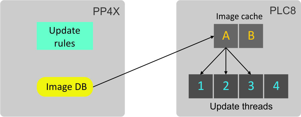
Figure 52 – ONT firmware update infrastructure
The 128 MB ONT firmware files storage is located at PP4X module. The maximum size of an ONT firmware file is 24 MB. When a file is stored in the storage, it can be used by PLC8 modules. See section ONT firmware files management for detailed description of file management schemes for ONT firmware.
At the start of the ONT firmware update the firmware file is copied to the cache of PLC8 module. This takes about 1-2 minutes. Then an update stream transfers the file to ONT in small parts via OMCI. File transfer takes more time – usually about 10 minutes for a 16 MB file with window size of 96 kB. Thus, the firmware update for an ONT may totally take up to 12 minutes.
When the update is completed, the update file is not removed from the cache and can be used again later. This reduces the time required for further updates. However, the file can be replaced when both caches are full and a new firmware file should be used. To be replaced, the file should not be used by any update streams. If there are no unused files, the update operation will be put in a queue. It means that up to 4 ONTs with different firmware files can be simultaneously updated for each PLC8 module.
An access node can also update ONT firmware automatically. To control the mode, the following settings are provided. See section ONT firmware auto update configuration for description. There are two ONT auto update modes.
The immediate mode allows all ONTs to be updated within the shortest possible time because they are updated one by one. The mode's disadvantage is the necessary ONT reboot after activation of a new firmware image and, consequently, possible interruptions in operation of services.
The postpone mode is more delicate: a new update is performed only after the previously updated ONT firmware has been activated. User does not encounter any occasional difficulties with services operation. This mode may take more time to update all ONTs.
A decision to launch ONT update is made based on auto update rules. Every auto update rule contains the following information:
- unique rule name, which allows rule modification;
- ONT type (the Equipment-ID field);
- firmware version1, which indicates that the firmware should be updated;
- name of the file from the ONT firmware files storage that should be used for update;
- rule scope: global or local.
ONT firmware auto update can be activated/deactivated based on global or local rules. For more details on auto update rules see section ONT auto update rules.
1 Firmware version field allows negation, i. e. the use of the prefix "!". This allows using of complex rules such as: if firmware version is not equal 1.2.3, use the 1_2_3.bin file for update.
ONT firmware files management
To download the firmware file, use the copy command and specify the file name and the address of the TFTP server as parameters:
ma4000# copy tftp://192.168.1.100/ntp-rg-d3.20.2.169.fw.bin fs://ont-firmware Download file from TFTP-server.. .......................................... .......................................... ONT firmware vendor is Eltex Corporation, version 3.20.2.169 Write downloaded file to flash memory.. .......................................... ..........................................
Being downloaded, the ONT firmware file is moved to ONT firmware files storage in PP4X and can be used by PLC8 modules.
Use the show firmware ont command to view the content of the ONT firmware files storage in PP4X:
ma4000# show firmware ont ONT firmware images: ~~~~~~~~~~~~~~~~~~~~ # Filename Version Hardware ----- ------------------------------ ----------------------------- --------------- 1 ntp-rg-revb-d3.20.2.174.fw.bin ---- ------------------------------ ----------------------------- --------------- 2 ntp-rg-revb-d3.20.2.170.fw.bin ---- ------------------------------ ----------------------------- --------------- 3 ntp-rg-d3.20.2.169.fw.bin ---- ------------------------------ ----------------------------- --------------- 4 ntp-rg-d3.20.2.165.fw.bin ---- ------------------------------ ----------------------------- ---------------
To remove a firmware file, use the firmware ont delete image command with the file's name:
ma4000# firmware ont delete image ntp-rg-d3.20.2.165.fw.bin Firmware deleting finished.
ONT firmware manual update
This method is used to update the ONTs which are activated at the time of update.
To perform a forced update of an ONT, use the update ont command with the ONT's ID and name of the ONT firmware file available in PP4X storages:
ma4000# update ont 0/0 ntp-rg-r3.20.2.123.fw.bin Task for updated successfully created. ONT firmware will be updated in 20 minutes or more
A task will be created to update the ONT firmware with the specified ID. The task will end with an error for the ONTs, which are not connected.
ONT firmware auto update configuration
ONT auto update modes
ONT auto update has two modes: immediate and postpone.
Step 1. Activate the update mode by the firmware ont auto update command:
ma4000# firmware ont auto update postpone
Step 2. Apply the changes by using the commit command:
ma4000# commit
You can view the configured mode with the help of the show firmware ont auto update state command:
ma4000# show firmware ont auto update state Auto-update ONT: postpone
Step 3. To disable the ONT firmware auto update, use the no firmware ont auto update enable command:
ma4000# no firmware ont auto update enable
ONT auto update rules
Step 1. Use the firmware ont auto update add command to add a new auto update rule. Specify the rule's unique name, ONT type (Equipment-ID), firmware version to be updated, name of the file in the ONT firmware files storage to be used in the update, and the mode as parameters:
ma4000# firmware ont auto update add name2 NTP-RG 1.1.1 filename global
Step 2. To display the list of auto update rules, use the show firmware ont auto update entries command:
ma4000# show firmware ont auto update entries Description EquipmentID FWVersion FileName Mode Rule1|NTP-RG-1402G-W|3.20.2.123|ntp-rg-d3.20.2.124.fw.bin|global Rule2|NTP-RG-1402G-W|3.20.2.124|ntp-rg-d3.20.2.125.fw.bin|global
Step 3. Use the firmware ont auto update delete command to remove an auto update rule:
ma4000# firmware ont auto update delete Rule1
APPENDIX A. Configuring services on ONT Ericsson, Atron, CIG
Introduction
Starting with version 3.30.0, ONT support has been added for Ericsson T063G, Ericsson T073G, Atron RFT620, Atron PSG590, CIG G-25A-J80. In setting up services on these ONTs, there are some features presented below.
VoIP configuration
To configure VoIP, you need to create two new profiles: cross-connect type voice, profile voice.
Step 1. Create required profiles:
MA4000(config)# profile cross-connect "VOICE-ERCS"
MA4000(config-cross-connect)("VOICE-ERCS")# description "For VOICE ont Ericsson"
MA4000(config-cross-connect)("VOICE-ERCS")# bridge
MA4000(config-cross-connect)("VOICE-ERCS")# bridge group "5"
MA4000(config-cross-connect)("VOICE-ERCS")# outer vid 354
MA4000(config-cross-connect)("VOICE-ERCS")# user vid 354
MA4000(config-cross-connect)("VOICE-ERCS")# type "voice"
MA4000(config-cross-connect)("VOICE-ERCS")# exit
MA4000(config)#
MA4000(config)# profile voice "voice-00-ERCS"
MA4000(config-voice)("voice-00-ERCS")# sip proxy "123.test.ru"
MA4000(config-voice)("voice-00-ERCS")# sip outbound-proxy "172.20.20.201"
MA4000(config-voice)("voice-00-ERCS")# sip domain "123.test.ru"
MA4000(config-voice)("voice-00-ERCS")# exit
Step 2. Assign profiles to ONT and configure additional VoIP data:
MA4000(config)# interface ont 0/2 MA4000(config)(if-ont-0/2)# service 0 profile cross-connect "VOICE-ERCS" dba "dba-00" MA4000(config)(if-ont-0/2)# profile voice "voice-00-ERCS" MA4000(config)(if-ont-0/2)# voice port 0 number "402153" MA4000(config)(if-ont-0/2)# voice port 0 authentication username "402153" MA4000(config)(if-ont-0/2)# voice port 0 authentication password "QFxy2EzfVdrL1"
Step 3. If necessary, configure Value Added Services for the ONT:
MA4000(config)(if-ont-0/2)# voice fax-mode t38 MA4000(config)(if-ont-0/2)# voice features call-presentation special-dialtone MA4000(config)(if-ont-0/2)# voice features call-presentation visual MA4000(config)(if-ont-0/2)# voice features call-presentation call-forward MA4000(config)(if-ont-0/2)# voice features call-progress 3way MA4000(config)(if-ont-0/2)# voice features call-progress transfer MA4000(config)(if-ont-0/2)# voice features call-progress hold MA4000(config)(if-ont-0/2)# voice features call-progress park MA4000(config)(if-ont-0/2)# voice features call-progress emergency-hold MA4000(config)(if-ont-0/2)# voice features call-progress 6way MA4000(config)(if-ont-0/2)# voice features call-wait enable MA4000(config)(if-ont-0/2)# voice features call-wait call-id-annonce MA4000(config)(if-ont-0/2)# voice features cid call-number MA4000(config)(if-ont-0/2)# voice features cid call-name MA4000(config)(if-ont-0/2)# voice features cid cid-number MA4000(config)(if-ont-0/2)# voice features cid cid-name
Step 4. Apply changes:
MA4000(config)(if-ont-0/2)# do commit