Subscriber terminal
NTU-MD500P
Software version 2.4.7 (09.2022)
List of changes
Document version | Software | Release date | Changes |
|---|---|---|---|
| Version 1.1 | 2.4.7 | 09.2022 | Second publication |
Version 1.0 | 1.0.1 | 04.2021 | First publication |
Introduction
GPON network belongs to one of the varieties of passive optical PON networks. This is one of the most modern and effective solutions for "last mile", which allows significant savings on cable infrastructure and provides data transmission speed of up to 2.5 Gbps downlink and 1.25 Gbps uplink. The use of GPON-based solutions in access networks makes it possible to provide end users with new IP services together with traditional ones.
The main advantage of GPON is the use of a single line terminal (OLT) for multiple subscriber devices (ONT). OLT is a converter of Gigabit Ethernet and GPON interfaces, which serves to connect the PON network with higher-level data transmission networks. The ONT device is designed to connect customers' equipment to broadband access services. It can be used in residential areas and business centers.
The user manual describes the purpose, main technical specifications, configuration rules and monitoring of the optical network terminal NTU-MD500P.
Notes and Warnings
The tips contain important information or recommendations for using and configuring the device.
The notes contain additional information on using and configuring the device.
Warnings inform of the situations when actions may harm the device or a user, lead to fault operation of the device or data loss.
Product Description
Purpose
NTU-MD500P is an optical network terminal that has four 10/100/1000BASE-T ports with support for IEEE 802.3at PoE+ technology. NTU-MD500P provides up to 30 W of power on 10/100/1000BASE-T ports with a PoE power budget of 65 W.
Support for PoE technology allows NTU-MD500P to supply power via UTP cable to IP phones, wireless access points, IP cameras and other PoE-enabled devices.
The advantage of GPON technology is the optimum use of bandwidth. This technology is the next step to provide new high-speed internet connection at home and in offices. Designed to deploy a network inside a home or building, NTU-MD500P provides reliable connection with high bandwidth over long distances for users living and working in remote apartment buildings and business centers.
Overview
NTU-MD500P has the following interfaces:
- 1 PON SC/APC port for connecting to the operator's network (WAN);
- 4 Ethernet RJ-45 LAN ports (10/100/1000BASE-T) for connecting network devices (LAN).
NTU-MD500P supports the following functions:
- PoE management and monitoring via OMCI:
- ONU-G::PSE overload yellow;
- ONU-G::PSE overload red;
- Physical path termination point Ethernet UNI::Power control;
- Power over Ethernet control::Operational state;
- Power over Ethernet control::Power detection status;
- Power over Ethernet control::Power classification status;
- Power over Ethernet control::Current Power Consumption;
- Power over Ethernet control::AVC;
- Power over Ethernet control::Power priority.
- Network functions:
- support for TR-069;
- operation in "bridge" or "router" mode;
- PPPoE (auto, PAP-, CHAP-, MSCHAP-authorization);
- IPoE (DHCP client and static);
- DNS (Domain Name System);
- DynDNS (Dynamic DNS);
- UPnP (Universal Plug and Play);
- VPN in L2TP mode;
L2TP over IPsec;
IPsec (trasport mode);
NAT (Network Address Translation);
- NTP (Network Time Protocol);
- QoS (quality of service mechanisms);
- IGMP-snooping;
- IGMP proxy;
- VLAN according to IEEE 802.1Q.
- Firmware update via TR-069, OMCI, HTTP, TFTP;
- Remote monitoring and configuration:
- SNMP-agent OLT;
- CLI OLT.
The figure below shows the use case of NTU-MD500P.
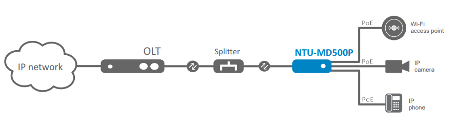
Figure 1 — NTU-MD500P use case
Technical specifications
The main technical parameters of the terminal are given in Table 1:
Table 1 — Technical specifications
| Parameters of LAN Ethernet interfaces | |
Number of interfaces | 4 |
|---|---|
Electrical connector | RJ-45 |
Data rate | Auto-detection, 10/100/1000 Mbps, duplex/half duplex |
Supported standards | IEEE 802.3i 10BASE-T Ethernet |
| PON interface parameters | |
Number of interfaces | 1 |
| Supported standards | ITU-T G.984.x Gigabit-capable passive optical networks (GPON) |
| Connector type | SC/APC corresponds to ITU-T G.984.2, ITU-T G.984.5 Filter, FSAN Class B+, SFF-8472 |
| Transmission medium | Fiber optic cable SMF — 9/125, G.652 |
| Split ratio | Up to 1:128 |
| Maximum distance | 20 km |
| Transmitter: | 1310 nm |
| 1244 Mbps |
| From +0.5 dBm to +5 dBm |
| 1 nm |
| Receiver: | 1490 nm |
| 2488 Mbps |
| From -8 to -28, BER≤1.0x10⁻¹⁰ |
| Optical overload of the receiver | -8 dBm |
| Management | |
| Local management | Web, CLI |
| Remote control | TR-069, OMCI |
| Firmware update | OMCI, TR-069, HTTP, TFTP |
| Access restriction | By password |
| General parameters | |
| Power supply | 110-250 V AC, 50-60 Hz |
| Maximum power consumption | 80 W |
| Operating temperature range | From 0 to +40 °C |
| Relative humidity | No more than 80% |
| Dimensions (W × H × D) | 267 × 44 × 178 mm |
| Form factor | 19", size 1U |
| Weight | 1.56 kg |
Design
This section describes design and indicators layout of the device. Images of the front, back and side panels of the device are shown in the section, connectors, LED indicators and controls are described.
NTU-MD500P is enclosed in a metal case suitable for 19” rack, the height of the case is 1U.
Front panel layout
The device front panel layout is shown in Figure 2.
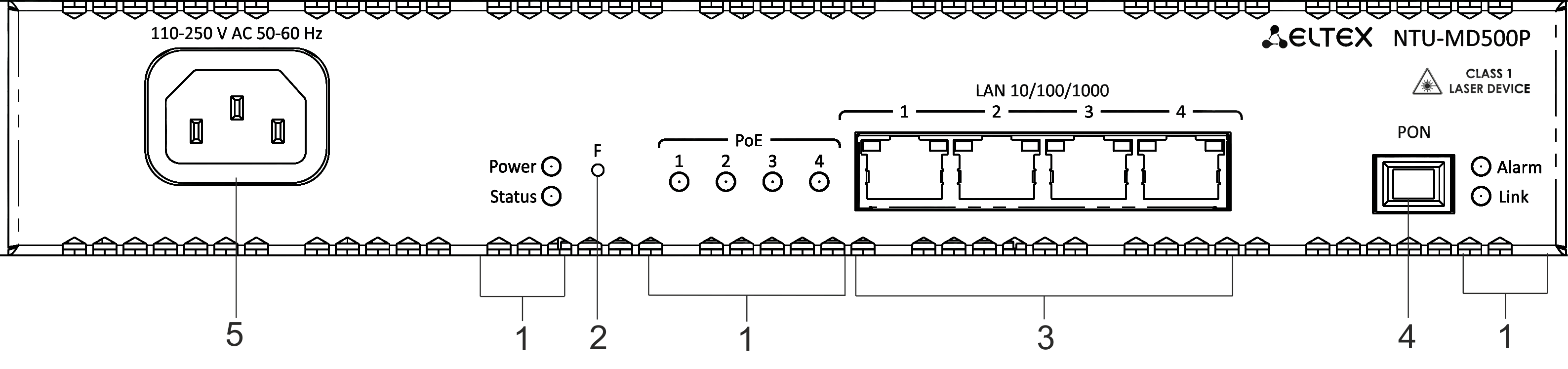
Figure 2 — NTU-MD500P front panel
Table 2 — Description of connectors and front panel controls
№ | Front panel element | Description | |
|---|---|---|---|
1 | Power | Device power indicator | |
Status | Device operation indicator | ||
Alarm | Indicator of optical signal absence | ||
Link | Indicator of optical interface operation | ||
PoE 1-4 | Status indicators of PoE ports | ||
2 | F | Functional button to restart the device and reset to factory settings: - pressing the button for less than 10 seconds restarts the device; - pressing the button for more than 10 seconds resets the device to the factory settings. | |
3 | LAN 10/100/1000 1..4 | 4 RJ-45 ports for connecting network devices | |
4 | PON | PON SC port (socket) of the GPON optical interface | |
5 | 110-250 V AC 50-60 Hz | Connector for AC power source | |
Side and back panels of the device
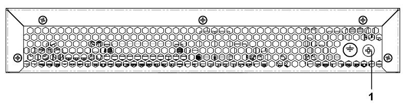
Figure 3 — NTU-MD500P back panel
№ | Back panel element | |
|---|---|---|
1 | Earth bonding point | |
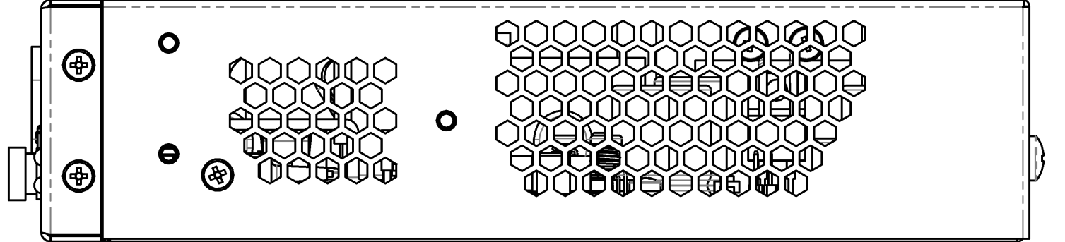
Figure 4 — NTU-MD500P left-side panel
There are ventilation grilles on the side and back panels of the device, which serve to remove heat. Do not cover the ventilation grilles, it can lead to overheating of the device components and cause malfunctioning. See recommendations for device installation in the Installing and connecting NTU-MD500P section.
Light indication
System indicators (Power, Status, Alarm, Link) are used to determine the operation status of the device nodes.
Table 3 — Light indication of device status
| Indicator name | Indicator status | Device status |
|---|---|---|
| Power | Solid green | The power is on, the device is operating normally |
| Off | The power is off | |
| Status | Solid red | The moment the drivers are lauching |
| Solid green | The device has a configuration which differs from the default one | |
| Green, flashing slowly | The default configuration is set on the device | |
| PoE 1-4 | Solid green | The PoE consumer is connected, the power supply is in on (the indicator corresponds to a port). |
Solid red | PoE error on port | |
Off | PoE consumer is not connected | |
| Alarm | Off | Normal operation of the device |
| Solid red | There is no optical signal | |
| Link | Off | The device is loading |
| Green, flashing fast | Getting settings via OMCI | |
| Solid green | The device has been successfully configured via OMCI. | |
| Green, flashing slowly | Configuration is absent (authorization) | |
| Red, flashing slowly | No signal from OLT | |
| LAN P1..P4 | Green | 10/100 Mbps connection has been established |
| Orange | 1000 Mbps connection has been established | |
| Flashing | The process of packet data transmission |
Delivery package
The basic delivery package of NTU-MD500P device includes:
- Subscriber terminal NTU-MD500P;
- Power cord with euro plug C-13, 1.8 m;
- Mounting kit for installing into 19" rack;
- Technical passport.
Installing and connecting NTU-MD500P
Operating conditions and installation procedure
This chapter describes procedure of installation into 19'' rack and connection to a power supply.
Safety requirements
General requirements
When working with the device, it is necessary to comply with safety regulations for the operation with electrical installations.
It is forbidden to work with the device to persons who are not allowed to operation in accordance with the safety requirements.
- The operation of the device must be carried out by engineering and technical personnel who have received special training.
- Connect only fault-free auxiliary equipment to the terminal.
- The terminal is designed for twenty-four-hour operation under the following conditions:
- ambient temperature from 0 to +40 ° C;
- relative humidity up to 80 % at 25 °C;
- atmospheric pressure from 6.0×10⁴ Pa to 10.7×10⁴ Pa (from 450 to 800 mm Hg).
- Do not expose the device to mechanical shocks and vibrations, as well as smoke, dust, water, chemicals.
- In order to avoid overheating of the device components and disruption of its operation, it is forbidden to cover the ventilation grilles and place objects on the surface of the device.
Electrical safety requirements
- Before connecting the terminal to a power source, it is necessary to ground the device case using the earth bonding point (Figure 3). A grounding wire must be securely fixed to the earth bonding point. The resistance value between the earth bonding point and ground bus must not exceed 0.1 Ohm. Before connecting measuring instruments and a PC to the device, they must be previously grounded. The potential difference between the device case and measuring instruments should not exceed 1 V.
- Before turning on the device, make sure that the cables are intact and securely attached to the connectors.
- When installing or removing the case, make sure that the power supply of the device is switched off.
Installation procedure
Before installing and switching on, it is necessary to check the device for visible mechanical damage. In case of damage, stop installing the device, draw up an appropriate report and contact the supplier. If the device has been exposed to low temperature for a long period of time, it should be kept at room temperature for two hours before operation. After a long stay of the device in high humidity conditions, it is necessary to keep it under normal conditions for at least 12 hours before switching on.
Mounting
The terminal package includes brackets for installation in a rack and screws for fixing brackets to the device case. To install the brackets:
- Step 1. Align the four screw holes on the bracket with the same holes on the side panel of the device.
- Step 2. Using a screwdriver, attach the bracket with screws to the case.
- Step 3. Repeat steps 1 and 2 for the second bracket.
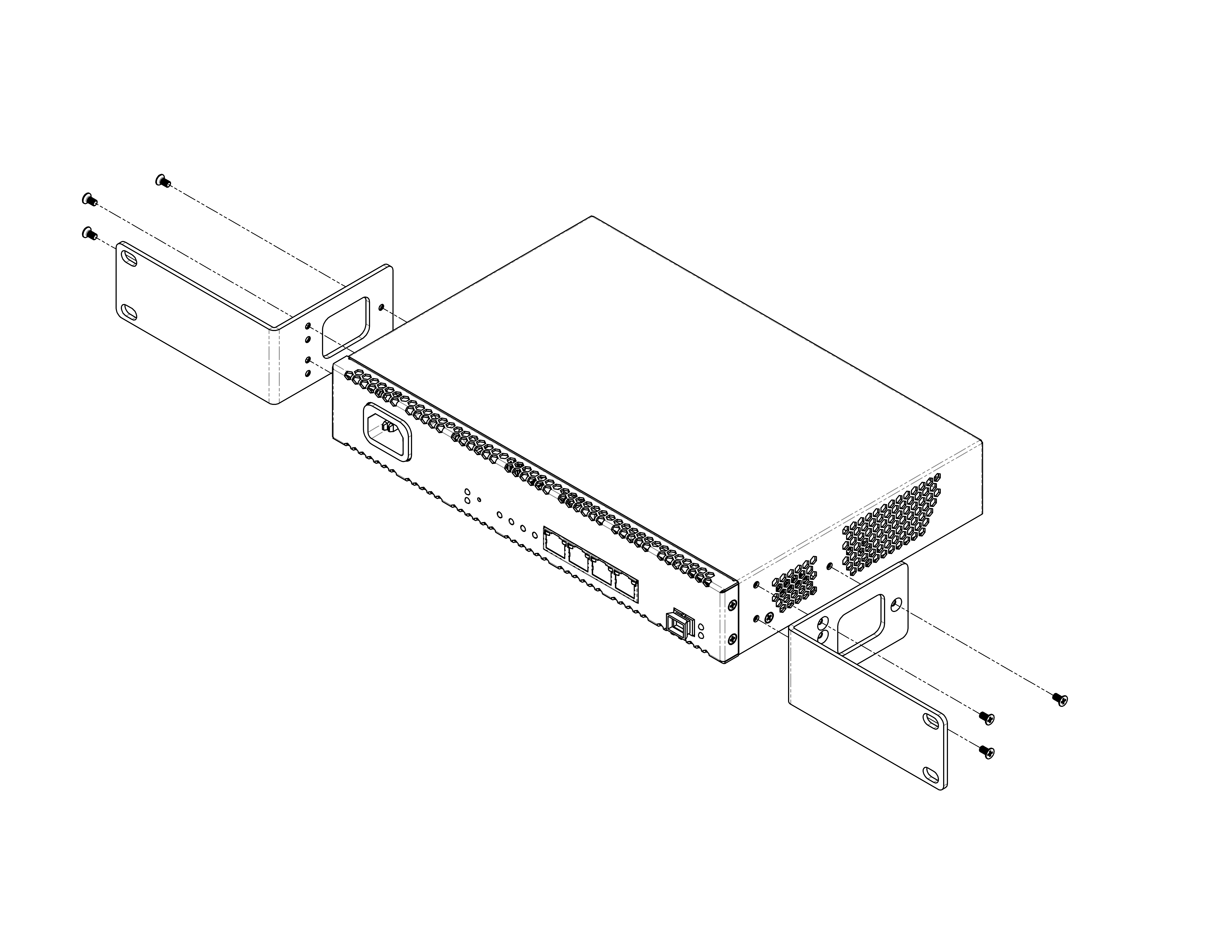
Figure 5 — Mounting brackets
Installing into a rack
To install the device in a rack:
- Step 1. Attach the device to the vertical rails of the rack.
- Step 2. Align the holes of the brackets with the holes on the rack rails. Use the holes in the rails at the same level on both sides of the rack so that the device will be positioned strictly horizontally.
- Step 3. Use a screwdriver to attach the device to the rack with screws.
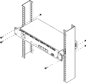
Figure 6 — Mounting brackets
The device has horizontal ventilation. Ventilation grilles are located on the side panels of the device. Do not cover the ventilation grilles to avoid overheating of the device components and malfunctioning.
To avoid overheating and provide the necessary ventilation, the device must be placed so that there is at least 10 cm of free space above and below it.
Connecting the device
1. Connect LAN port of NTU-MD500P and Ethernet port of your PC using an Ethernet cable.
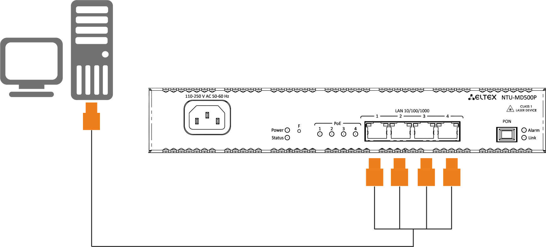
Figure 7 — Connecting the device to the computer
2. Connect the optical cable provided by the Internet service provider to the PON connector of the device.
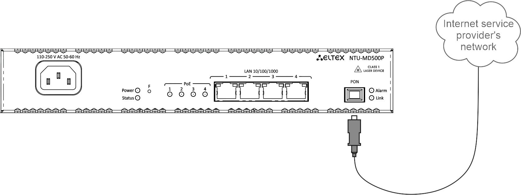
Figure 8 — Connecting the device to an Internet service provider's network
3. Connect the terminal to 220 V power supply network using the power adapter included into the delivery package. Wait until the device is fully loaded.
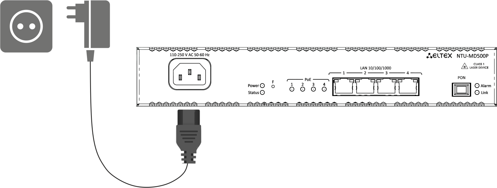
Figure 9 — Connecting the device to the power supply
Device architecture
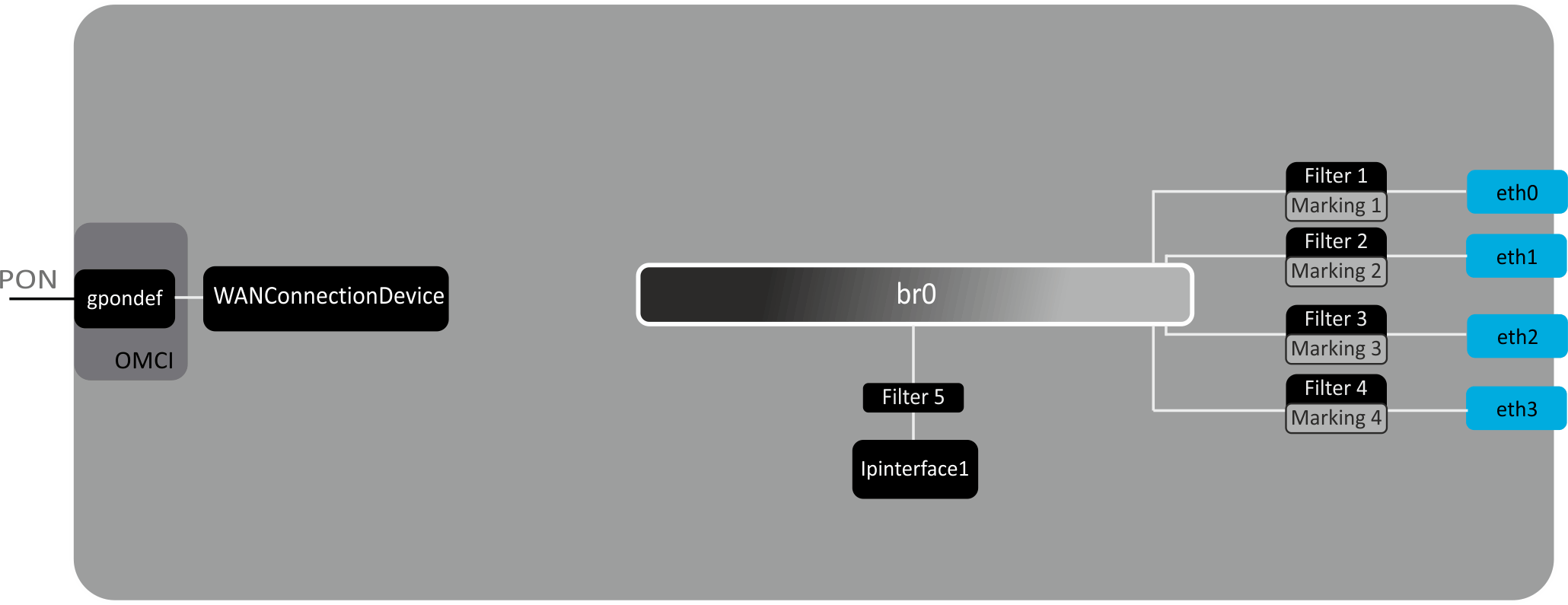
Figure 10 — Logical architecture of the device with the factory configuration
The main elements of the device:
- Optical transceiver (SFF module) is designed to convert an optical signal into an electrical one;
- Processor (PON chip) — is a converter of Ethernet and GPON interfaces.
In the factory configuration, the following logic blocks are present (Figure 10):
- Br0;
- eth0…3;
- IPInterface1.
The br0 block in this case is intended for combining LAN ports into one group.
The eth0..3 blocks are physically Ethernet ports with an RJ-45 connector for connecting a PC, STB or other network devices. Logically included in the br0 block.
The Filter and Marking blocks are designed to put local interfaces in one group (in the br0 block). These blocks are responsible for the traffic transmission rules, the Filter blocks are responsible for incoming traffic on the interface, the Marking blocks are responsible for outgoing traffic.
The ipinterface1 block is a logical object where IP address for access to the local network is stored, as well as a DHCP server that distributes addresses to clients.
Configuring the device via web interface. Admin access.
Getting started
To configure the device, you need to connect the device via a web browser:
- Open a web browser (web page viewer), for example, Firefox, Google Chrome.
Type the device IP address in the browser's address bar
The default IP address: 192.168.0.1, subnet mask: 255.255.255.0
If the connection is successful, a page with the authorization request will be displayed in the browser window:

Enter username and password
Default user name — admin, password — password.
- Click the "Login" button. The starting page of the device's web interface will be displayed in the browser window.
Changing the password
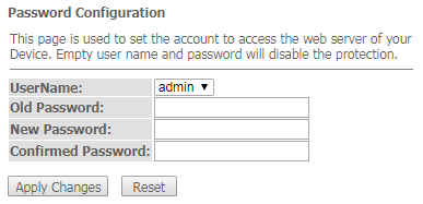
In order to avoid unauthorized access, it is recommended to change the password for further operation. To change the password in the menu Admin, section "Password", in the field "Old Password" enter the current password in the fields "New Password" and "Confirm new password" enter a new password. To save changes, click the Apply Changes button.
Elements of the web interface
General view of the device configuration window is shown below.
The user interface can be divided into 3 parts :
- The navigation tree of the device settings menu.
- The main window of selected section settings.
- Change user button.
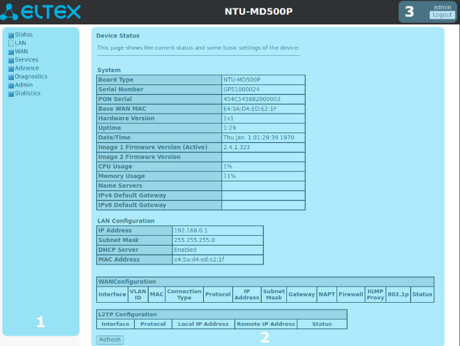
Status menu. Device information
Device submenu. General information on the device
The section displays general information on the device, the main parameters of LAN and WAN interfaces.
Status → Device
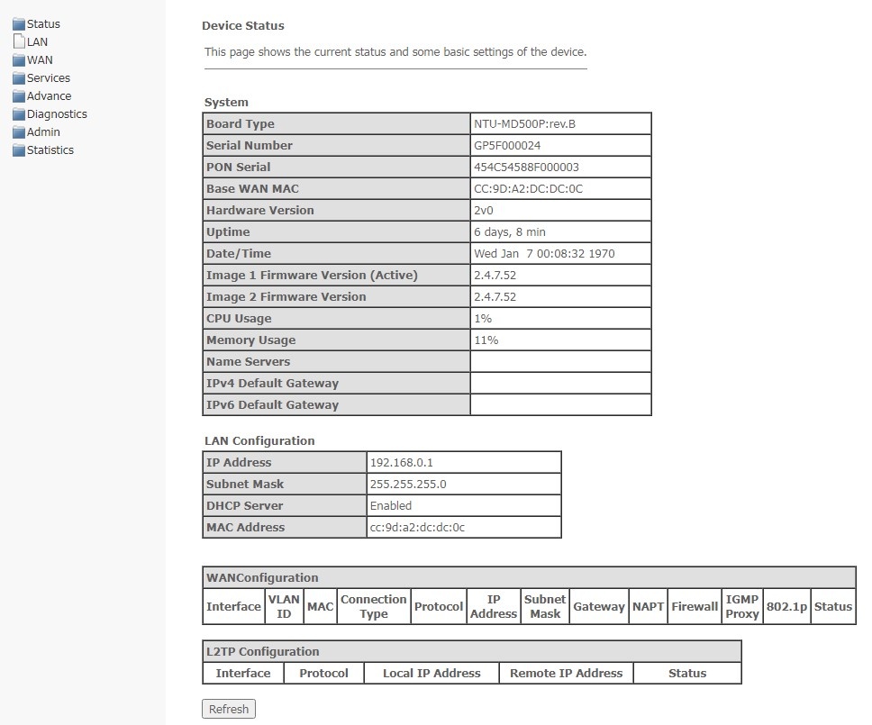
System
Board Type — hardware model;
Serial Number — serial number of the device;
PON Serial — serial number of the device in PON network;
Base WAN MAC — WAN MAC address of the device;
Hardware Version — hardware version of the device;
Uptime — device operation time;
Date/Time — the current time on the device;
Image 1 Firmware Version (Active) — current firmware version;
Image 2 Firmware Version — backup software version;
CPU Usage — percentage of CPU usage;
Memory Usage — percentage of memory usage;
Name Servers — name of DNS server;
IPv4 Default Gateway;
IPv6 Default Gateway.
LAN Configuration
IP Address — IP address of the device;
Subnet Mask — network mask of the device;
DHCP Server — status of DHCP server;
MAC Address — MAC address of the device.
WAN Configuration
- Interface — interface name;
- VLAN ID — VLAN ID of the interface;
- MAC — MAC address of the interface;
- Connection Type;
- Protocol — the protocol used;
- IP Address — IP address of the interface;
- Subnet Mask;
- Gateway;
- NAPT — NAPT state;
- Firewall — firewall status;
- IGMP Proxy — IGMP Proxy status;
- 802.1p — 802.1p mark;
- Status — interface status.
L2TP Configuration
- Interface — interface name;
- Protocol — the protocol used;
- Local IP Address — the IP address of the L2TP interface;
- Remote IP Address — server IP address;
- Status — interface status.
To update the data on the page, click Refresh.
IPv6 Status submenu. IPv6 System Information
The section displays the current status of the IPv6 system.
Status → IPv6
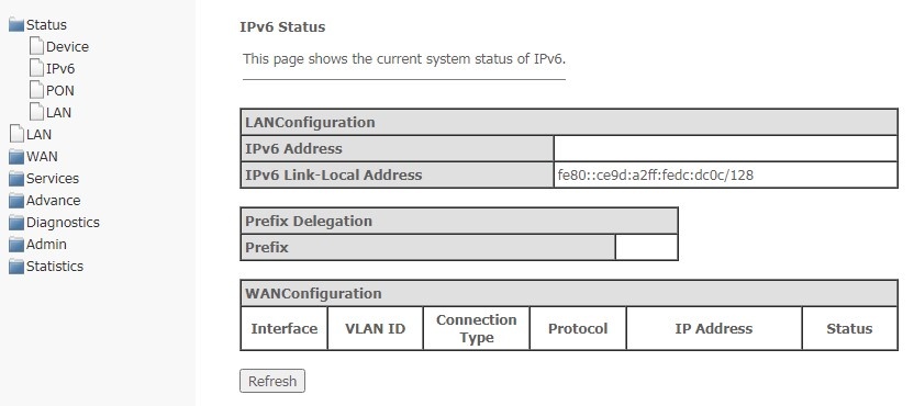
LAN Configuration
IPv6 Address;
IPv6 Link-Local Address — local IPv6 address.
Prefix Delegation
- Prefix — prefix of IPv6 address.
WAN Configuration
- Interface — interface name;
- VLAN ID — VLAN ID of the interface;
- Connection Type;
- Protocol — the protocol used;
- IP Address — IP address of the interface;
- Status — interface status.
To update the data on the page, click Refresh.
PON submenu. Optical module status
The section shows the current state of the PON interface.
Status → PON
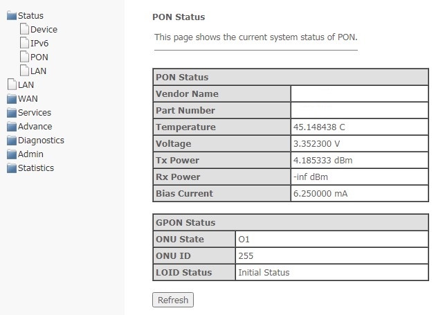
PON Status
- Vendor Name — PON chipset vendor's name;
- Part Number — part number of PON chipset;
- Temperature — current temperature;
- Voltage;
- Tx Power — transmission power;
- Rx Power — signal power at reception;
- Bias Current.
GPON Status
- ONU State — a status of authorization on OLT (O1 -> O2 -> O3 -> O4 -> O5 );
- ONU ID — device ID on OLT;
- LOID Status — authorization status on OLT (Initial -> Standby -> Serial Number -> Ranging - Operation).
To update the data on the page, click Refresh.
LAN submenu. Information on the status of LAN interface
In this section, you can view the main parameters of LAN interfaces.
Status → LAN
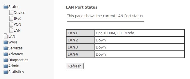
To update information in the table, click Refresh.
LAN menu. Configuring LAN interface
In this section, you can configure the main characteristics of wired and wireless LAN interfaces.
LAN
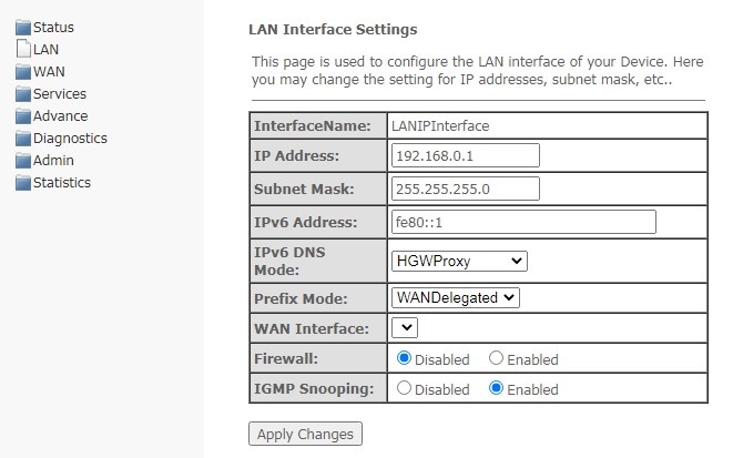
- InterfaceName — interface name;
- IP Address — IP address of the interface;
- Subnet Mask — interface subnet mask;
- IPv6 Address;
- IPv6 DNS Mode — configure the mode of domain names usage:
- HGWProxy — configure DNS mode for IPv6;
WANConnection — use the WAN interface to get the DNS server address;
Static — specify a static DNS server address (IPv6 DNS1, IPv6 DNS2).
- Prefix Mode — configure prefix reception mode (from WAN interface or statically):
- WANDelegated — the option of delegating prefixes received from the provider;
- Static — specify prefix statically.
- WAN Interface — select WAN interface to be used when WANDelegated.
- Firewall (Enabled/Disabled) — enable/disable firewall for LAN interface;
- IGMP Snooping (Enabled/Disabled) — enable/disable IGMP Snooping.
To save changes, click Apply Changes.
WAN menu. Configuring WAN interface
PON WAN submenu
In this section, you can configure the PON WAN parameters.
WAN → PON WAN
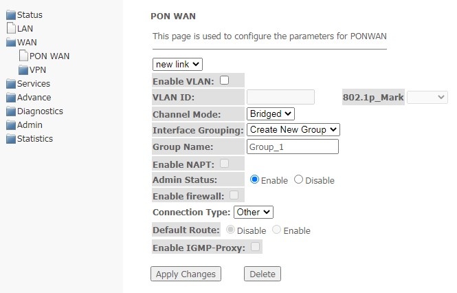
- Enable VLAN;
- VLAN ID — VLAN identification number;
- 802.1p_Mark — 802.1p priority;
- Channel Mode — VLAN interface operation mode;
- Bridged;
- IPoE — getting an address via the DHCP protocol;
- PPPoE — installing a point-to-point tunnel over Ethernet.
- Interface Grouping — select a group of interfaces;
- Group name — name of the interface group;
- Enable NAPT — enable NAPT (Network address port translation) function;
- Admin Status (Enable/Disable) — enable/disable administrative status;
- Enable Firewall;
- Connection Type — type of service provided on the WAN;
- Default Route (Enable/Disable) — enable/disable the use of the selected interface as a default gateway;
- Enable IGMP-Proxy — enable interception and forwarding of IGMP messages.
To save changes, click Apply Changes, to delete — Delete.
VPN submenu
L2TP submenu. Setting up an L2TP VPN
In this section, you can configure the virtual connection parameters L2TP VPN. The L2TP protocol is used to create a secure connection channel over the Internet between a remote user's computer and a local computer.
WAN → VPN → L2TP
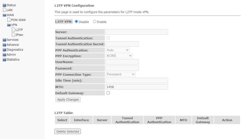
L2TP VPN is a mode in which access to the Internet is carried out through a tunnel using the L2TP protocol. When Enable is selected, the following parameters will be available for editing:
- Server — L2TP server address (domain name or IP address in IPv4 format);
- Tunnel Authentication — enable authentication;
- Tunnel Authentication Secret — authentication key;
- PPP Authentication — select authentication protocol used on L2TP server to validate connections;
- PPP Encryption — select data encryption protocol to be used (only for the CHAPMSv2 authentication method);
- UserName — the username for authorization on L2TP server;
- Password — password for authorization on L2TP server;
- PPP Connection Type;
- Idle Time (min) — idle time in seconds, breaks an inactive connection after a specified time (only for establishing a connection on demand (dial-on-demand));
- MTU — the maximum size of the data block transmitted over the network (the recommended value is 1462);
- Default Gateway — select whether the created tunnel will be a default L2TP gateway.
To save changes, click Apply Changes.
In the L2TP Table, you may view the status of a virtual L2TP VPN connection. To delete a certain entry, select the position and click Delete Selected.
IPsec submenu. Configuring IP Security
This page is used to configure settings for VPN in IPsec mode.
WAN → VPN → IPsec
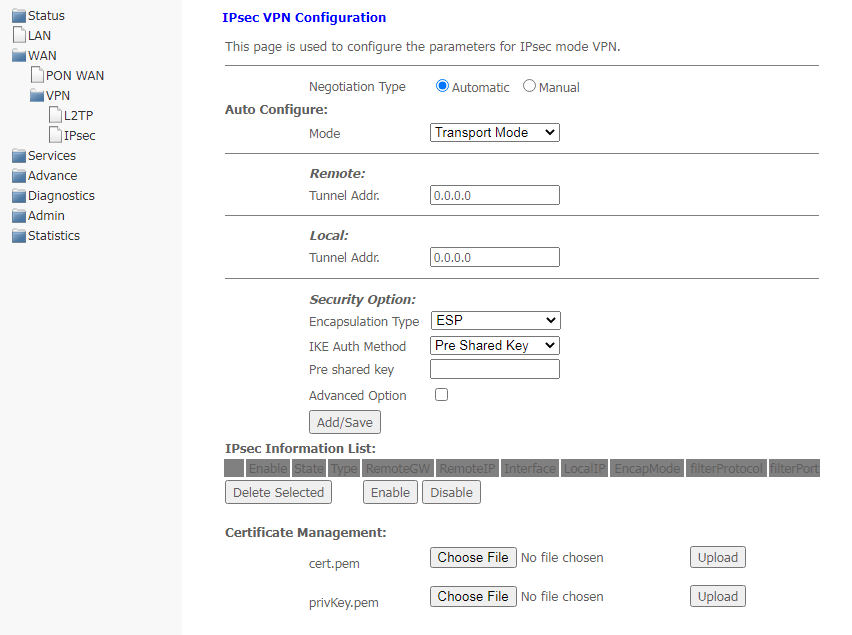
- Negotiation Type — select the type of negotiation: automatic or manual one;
- Negotiation Type — Automatic:
- Mode — IPsec operation mode (only transport mode is supported);
- Remote Tunnel Addr. — server IP address;
- Local Tunnel Addr. — local IP address;
- Security Option:
- Encapsulation Type;
- IKE Auth Method — IKE authentication method (Pre-shared key or Certificate);
- Pre shared key — set shared key (if using Pre-shared key method);
- Advanced Option — set up advanced security options:
- Filter Option:
- Protocol;
- Port.
- IKE Phase 1 — setting up the first phase:
- Negotiation Mode — negotiation mode: main or aggressive;
- Keepalive Time — session uptime in seconds;
- IKE Algorithm 1-4 — select key exchange algorithms.
- IKE Phase 2 — setting up the second phase:
- pfs_group mode — select PFS(DH) group;
- Encrypt Algorithm — encryption algorithm;
- Auth Algorithm — authentication algorithm;
- Keepalive Time — session uptime in seconds;
- Keepalive Byte — bytes to keep session active, KB.
- Filter Option:
- Negotiation Type — Manual:
- Mode — IPsec operation mode (only transport mode is supported);
- Remote Tunnel Addr. — server IP address;
- Local Tunnel Addr. — local IP address;
- Security Option:
- Encapsulation Type;
- Encapsulation Type — ESP:
- ESP Encrypt Algorithm — ESP encryption algorithm;
- ESP Encrypt Key — ESP encryption key;
- ESP Auth Algorithm — ESP authentication algorithm;
- ESP Auth Key — ESP authentication key.
- Encapsulation Type — AH:
- AH Auth Algorithm — AH authentication algorithm (md5 or sha1);
- AH Auth — AH authentication key.
- Encapsulation Type — ESP+AH:
- ESP Encrypt Algorithm — ESP encryption algorithm;
- ESP Encrypt Key — ESP encryption key;
- ESP Auth Algorithm — ESP authentication algorithm;
- ESP Auth Key — ESP authentication key;
- AH Auth Algorithm — AH authentication algorithm;
- AH Auth — AH authentication key.
- Encapsulation Type — ESP:
- Encapsulation Type;
- Advanced Option — set up advanced security options;
- Filter Option:
- Protocol;
- Port.
- Negotiation Type — Automatic:
- Certificate Management — select and download a management certificate. Click Select File to select the certificate then click Upload.
To save changes, click Add/Save.
In the table IPsec Information List, you can view, enable, disable and delete (Delete Selected) the created rules.
Services menu. Configuring services
DHCP Settings submenu. Configuring DHCP
In this section, a DHCP server or a DHCP repeater is configured.
- DHCP Mode — select operation mode:
- NONE — DHCP is disabled;
- DHCP Server — operation in the DHCP server mode;
- DHCP Relay — operation in the DHCP relay mode.
Services → DHCP (DHCP Server is selected)
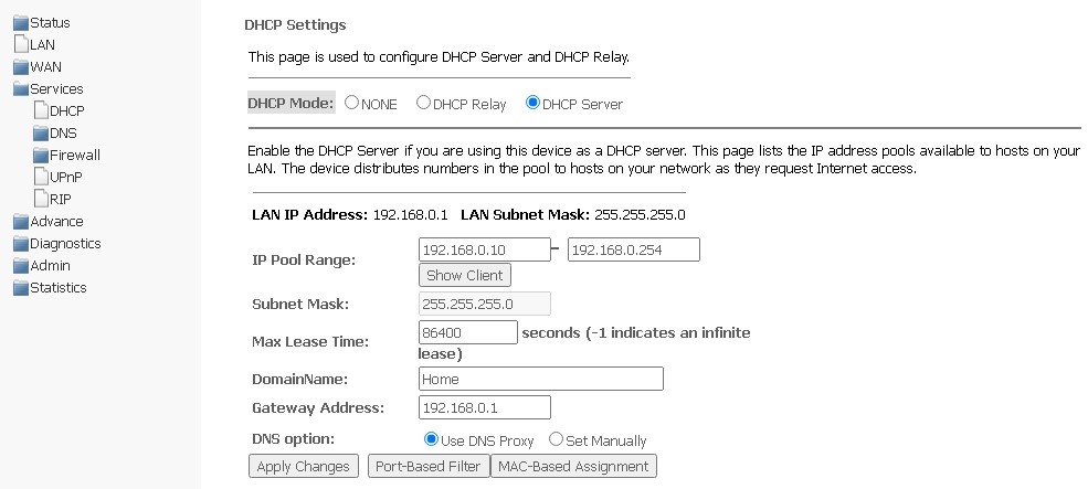
- IP Pool Range — the range of addresses issued to clients;
- Show Client — a button for viewing clients who have leased addresses. When enabled, a table with information about the DHCP clients leased addresses is displayed;
- Subnet Mask — subnet mask;
- Max Lease Time — maximum lease time, -1 for timeless lease;
- DomainName — domain name;
- Gateway Address — gateway address;
- DNS option — defines DNS operation:
- Use DNS relay — the ONT address will be issued as DNS and all requests will be relayed via ONT;
- Set manually — set DNS manually.
To save changes, click Apply Changes.
Port-Based Filter configures filtering according to ports, MAC-Based Assignment — according to MAC addresses.
Services → DHCP (DHCP Relay is selected)
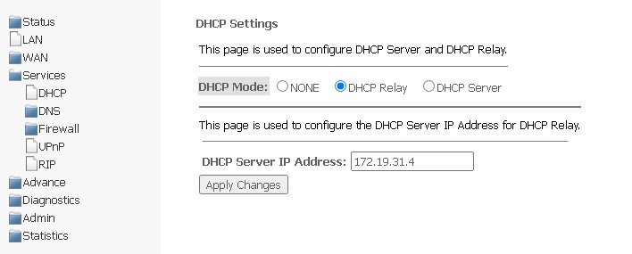
- DHCP Server IP Address — IP address of remote DHCP server, which will be used for DHCP Relay.
To save changes, click Apply Changes.
DNS submenu
Dynamic DNS submenu. Dynamic Domain Name System Settings
Dynamic DNS (dynamic domain name system) allows updating information on DNS server in real time and (optionally) in automatic mode. It is used to assign a permanent domain name to a device (computer, router, for example NTU-RG) having dynamic IP address. IP address might be obtained via IPCP in PPP connections or via DHCP.
Dynamic DNS is often used in local networks, where clients receive an IP address via DHCP, and then register their names in the local DNS server.
Services → DNS → Dynamic DNS
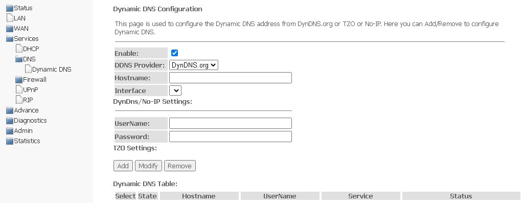
- Enable — when selected, DHCP server is used (network devices will receive IP addresses dynamically, from the range below);
- D-DNS Provider — select the type of D-DNS service (provider): DynDNS.org, No-IP.com;
- Hostname/Intereface — if you use another provider, you should specify the name (Hostname) and address (Interface) of the provider manually.
DynDns/No-IP Settings:
- UserName — user name;
- Password — password for authorization on the service selected for D-DNS operation.
The section displays Dynamic DNS Table with a list of available DNS and its parameters. To add an entry, click Add. To change/delete a position, select it and click Modify or Remove.
Firewall submenu. Configuring the firewall
ALG On-Off Configuration submenu. Enabling disabling ALG services.
In this section, you can enable or disable ALG and Pass Through services.
Services → Firewall → ALG
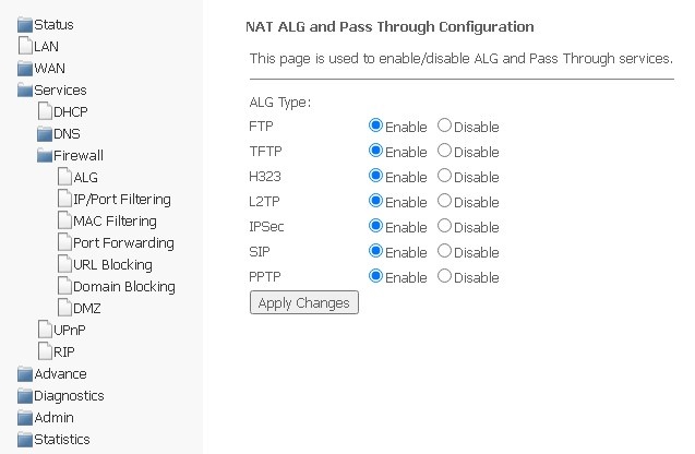
Please, do not forget to click Apply changes, to save changes made.
IP/Port Filtering submenu. Configuring address filtering
Address filtering settings are available in this menu. The IP filtering function allows you to filter traffic passing through the router according to IP addresses and ports. The use of such filters can be useful to protect or put restrictions on the local network.
Services → Firewall → IP/Port Filtering
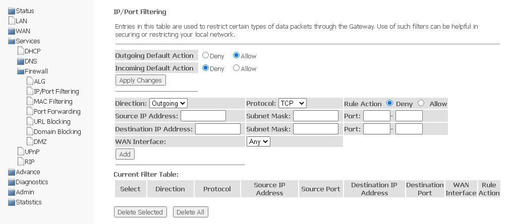
Default settings
- Outgoing Default Action Deny/Allow — filtering of outgoing packets;
- Incoming Default Action Deny/Allow — filtering of incoming packets.
To save changes made, click Apply Changes.
To add a filter, complete the appropriate fields and click Add:
- Direction — direction of packet transmission (outgoing/incoming);
- Protocol — filtering protocol;
- Rule Action — packet processing policy (Deny/Allow);
- Source IP Address;
- Subnet mask;
- Port.
- Destination IP Address;
- Subnet mask;
- Port.
- WAN Interface — incoming interface.
The added filters are displayed in Current Filter Table. The entries in this table are used to restrict certain types of data packets through the gateway. To delete a certain filter, select an entry and click the Delete selected button, to delete all filters — Delete All.
MAC Filtering submenu. MAC address filtering settings
The section helps to configure filtration based on MAC addresses, which allows you to forward or block traffic according to MAC address of the source and recipient.
Services → Firewall → MAC Filtering
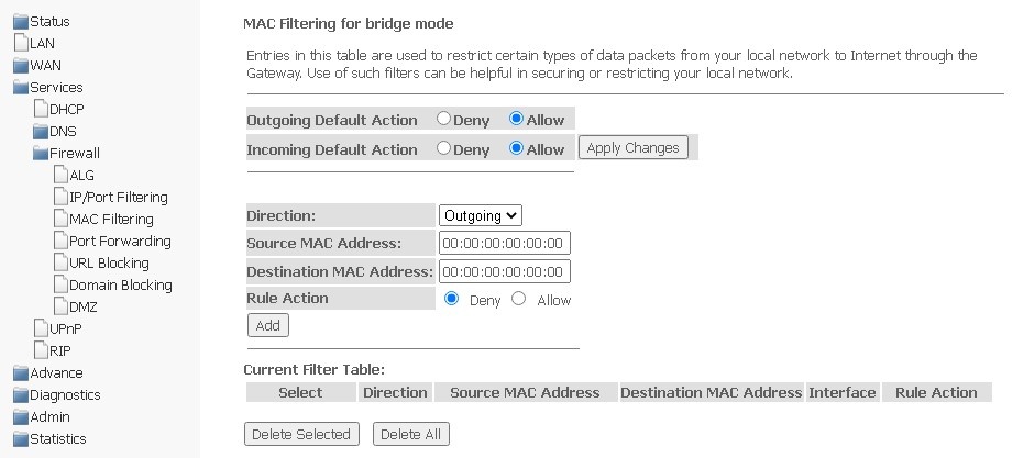
- Outgoing Default Action — default packet processing policy for outgoing traffic (Deny (drop out) / Allow (transmit));
- Incoming Default Action — default packet processing policy for incoming traffic (Deny (drop out) / Allow (transmit)).
To save changes, click Apply Changes.
To add a filter, complete the appropriate fields and click Add button:
- Direction — direction of packet transmission (outgoing/incoming);
- Source MAC Address — add source MAC address for which you want to set restriction/access.
- Destination MAC Address — add destination MAC address for which you want to set restriction/access.
- Rule Action — packet processing policy (Deny (drop out) / Allow (transmit));
- WAN Interface — incoming interface.
The added filters are displayed in the filter table below — Current Filter Table. The Rule action field displays the type of rule created (Allow or Deny traffic transmission). To delete a certain rule in the list, select it and click Delete Selected, to delete the entire list, click Delete All.
Port Forwarding submenu. Configuring port forwarding
This section contains Current Port Forwarding Table displaying information on port forwarding. Entries in this table allow you to automatically redirect shared network services to a specific computer behind the NAT firewall. These settings are only necessary if you want to deploy a host, such as a web server or mail server, on a private LAN behind the NAT firewall of the router you are using. To save changes, click Apply Changes.
Services → Firewall → Port Forwarding 
To add an entry to Current Port Forwarding Table, select Enable and complete the appropriate fields:
- Application — there are presets in the menu for port forwarding of different applications;
- Comment — write comment for the entry;
- Local IP — the local IP address to which the forwarding will be performed;
- Local port from/to — specify range of the local device ports for forwarding;
- Protocol — select protocol (TCP, UDP or both);
- Remote port from/to — specify initial port of the incoming connection. The field "Remote port to" will be filled in automatically;
- Interface — select interface;
- NAT-loopback — NAT loop allows you to transfer requests from the local network to the router, so, for example, you can check the operation of the created rules.
After completing the fields to add an entry, click Add. To delete a certain entry, select it and click the Delete Selected button, to delete the entire table — Delete All.
URL Blocking submenu. Configuring the Internet access restriction
The URL filter performs full analysis and control for access to certain Internet resources. In this section you may set and view a list of prohibited/allowed URLs to visit. Here you can add a prohibited/permitted FQDN (Fully Qualified Domain Name) with the Add button, keyword filtering is also possible. The added restrictions are displayed in URL Blocking Table and Keyword Filtering Table, to delete a specific URL or keyword from the table, click on it, and then on the Delete Selected button. To remove all restrictions, click Delete All.
Services → Firewall → URL Blocking
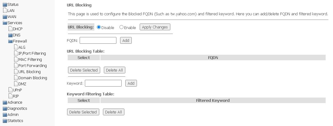
- URL Blocking (Enable/Disable) — enabling/disabling URL-Blocking;
- FQDN (Fully Qualified Domain Name) — full domain name;
- Keyword — keyword.
To save changes, click Apply Changes.
Domain Blocking submenu. Setting up Domain Blocking
This section is used to specify domain blocking.
Services → Firewall → Domain blocking
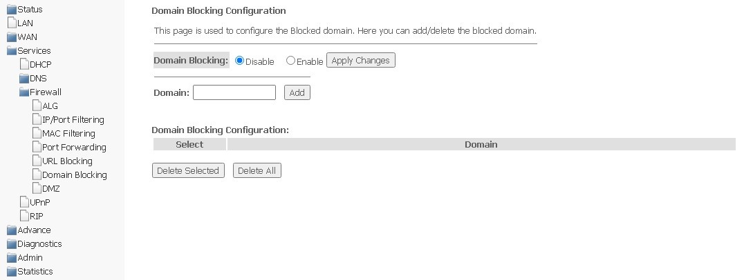
To block a domain, select Enable, complete the Domain field and click the Add button.
- Domain Blocking (Enable/Disable) — enable/disable blocking;
- Domain — domain name.
To save changes, use the Apply Changes button. All blocked domains are listed in the Domain Blocking Configuration table, to remove the block for a certain domain, select it and click Delete Selected, to remove all restrictions, click Delete All.
DMZ submenu. Configuring demilitarized zone
When setting IP address in the DMZ Host IP Address field, all requests from the external network that do not meet the Port Forwarding rules will be sent to the DMZ host (a trusted host with the specified address located in the local network).
Services → Firewall → DMZ
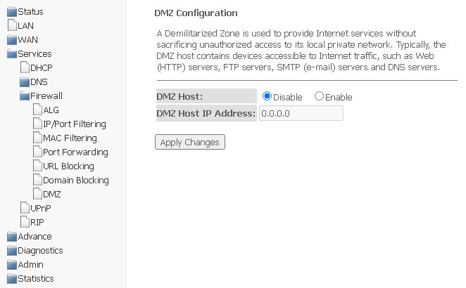
- DMZ Host (Enable/Disable) — enabling/disabling the host;
- DMZ Host IP Address — IP address.
To save changes, click the Apply Changes button.
UPnP submenu. Automatic configuration of network devices
In this section, you may configure the Universal Plug and Play (UPnP) function. UPnP provides compatibility with network equipment, software, and peripherals.
Services → UPnP
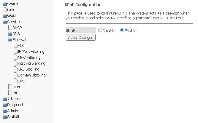
To use UPnP, you need to configure NAT on the active WAN interface.
- UPnP (Enable/Disable) — enable/disable UPnP function;
- WAN Interface — WAN interface on which the UPnP function will be enabled.
To save settings, click Apply Changes.
RIP submenu. Configuring dynamic routing
In this section you may select interfaces on devices that will use RIP and its version. Enable RIP if you are using this device as a RIP-enabled device to communicate with other users using the RIP Dynamic Routing protocol.
Services → RIP
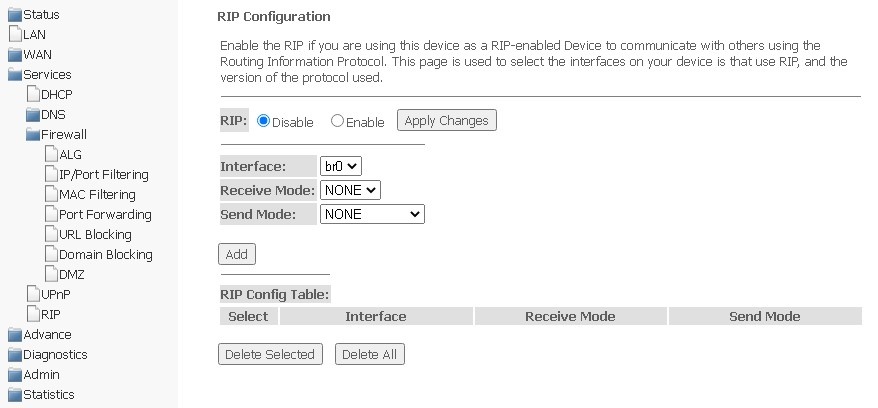
- RIP (Enable/Disable) — enabling/disabling the use of the RIP dynamic routing protocol;
To accept and save settings, click Apply Changes.
- Interface — the interface on which RIP will be launched;
- Receive Mode — incoming packet processing mode (NONE, RIP1, RIP2, both);
- Send Mode — transmission mode (NONE, RIP1, RIP2, RIP1 COMPAT).
RIP-enabled interfaces are displayed in RIP Config Table. To delete all entries in the table, click Delete All, to delete a certain entry from the list, select it and click Delete Selected.
Advance menu. Advanced settings
ARP Table submenu. Viewing the ARP protocol cache
The section displays a table of learned MAC addresses. The efficiency of ARP operation largely depends on the ARP cache, which is present on each host. The cache contains Internet addresses and their corresponding hardware addresses. The lifetime of each entry in the cache is 5 minutes from the moment the entry was created.
Advance → ARP table
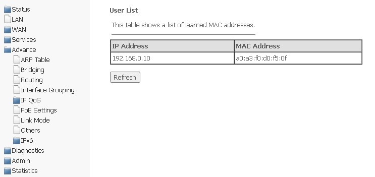
- IP Address — the client's IP address;
- MAC Address — the MAC address of the client.
To update information in the table, click Refresh.
Bridging submenu. Configuring Bridging parameters
In this section, you may configure bridge parameters. Here you can configure the lifetime of addresses in the MAC table, as well as enable/disable the 802.1d Spanning Tree protocol.
Advance → Bridging
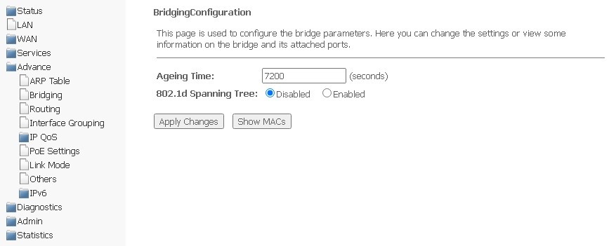
- Aging Time — lifetime of addresses (sec);
- 802.1d Spanning Tree (Enable/Disable) — enabling/disabling 802.1d Spanning Tree protocol.
To save changes, click Apply Changes.
To view information on the bridge and its connected ports, click Show MACs.
Advance → Bridging → Show MACs
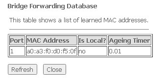
- Port — port number;
- MAC Address — MAC address;
- Is Local — local address;
- Aging Timer — address lifetime.
To update information in the table, click Refresh, to close — Close.
Routing submenu. Configuring routing
The section is used to configure static routing.
Advance → Routing
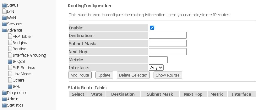
To add a static route, select Enable, complete the appropriate fields and click Add Route.
- Enable — add a route;
- Destination — destination address;
- Subnet Mask — subnet mask;
- Next Hop — next node;
- Metric — metric;
- Interface — interface.
Added static routes are displayed in Static Route Table. To update the information in the table, click Update, to delete an entry from the table, select it and click Delete Selected.
To view the routes that the device frequently accesses, click Show Routes, then IP Route Table will be displayed.
Advance → Routing → Show Routes
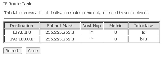
To update information in the table, click Refresh, to close it, click Close.
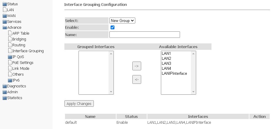
Interface grouping submenu. Combining interfaces into groups
In this section, you can combine interfaces into different groups. By default, all interfaces are in the same group. To transfer the interface to a new group, you should:
- Select a new group from the list below;
- Select interfaces from the list of Available interfaces;
- Press the arrow ← to move the interfaces to the group;
- Apply actions by clicking Apply Changes.
Advance → Interface grouping
IP QoS submenu. Configuring the quality of services provided (QoS)
QoS Policy submenu. Setting up QoS Queues
In this section, you can configure QoS queue policies for traffic processing.
Advance → IP QoS → QoS Policy
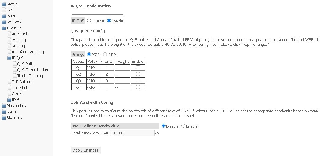
- IP QoS (Enable/Disable) — enable/disable configuration of QoS queues;
- Policy — select policy:
- PRIO — strict queue processing is used when selecting the PRIO policy. The smaller queue corresponds to the highest priority;
- WRR — weighted queue processing will be used when selecting the WRR policy. By default, weight for queues is distributed as 40:30:20:10.
QoS Bandwidth Config
Is used to configure the bandwidth of individual services.
- User defined Bandwidth (Enable/Disable) — enable restriction;
- Total Bandwidth Limit, (kb) — bandwidth limit, kbit.
To save changes, click Apply Changes.
QoS Classification submenu. Configuring traffic classification rules
On this page, you can specify according to which fields and their values the packet will be classified, as well as which hardware queue it will eventually belong to.
Advance → IP QoS → QoS Classification
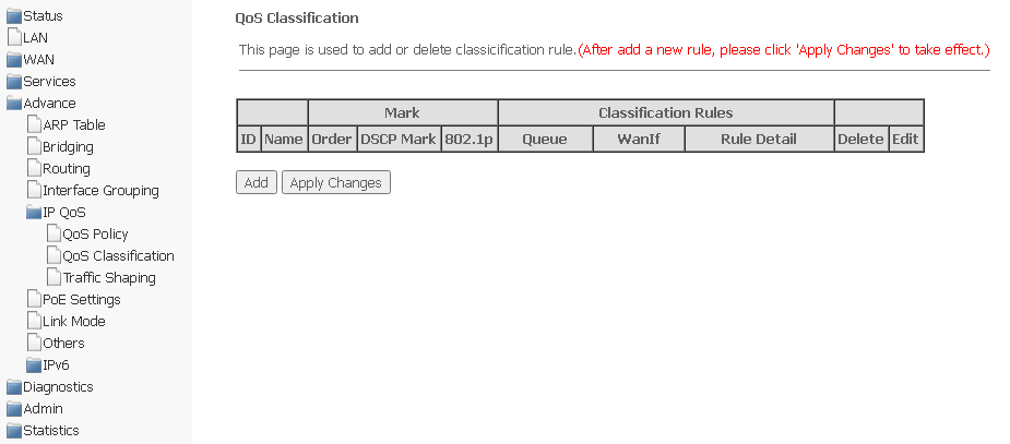
To add a rule, click Add and complete the appropriate fields.
Advance → IP QoS → QoS Classification → Add
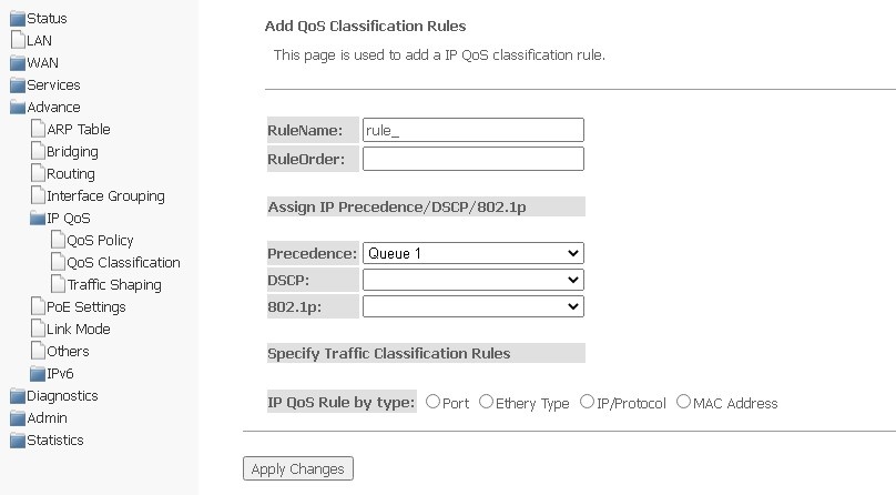
- RuleName — rule name;
- RuleOrder — sequence number.
Assing IP Precedence/DSCP/802.1p — setting up the assignment of IP fields.
- Precedence — queue selection;
- DSCP — priority in the IP packet header;
- 802.1p — priority label in 802.1Q .
Specify Traffic Classification Rules — select traffic classification rule.
- IP QoS Rule by type — select classification rule according to the type:
- Port — according to port;
- Physiacl Port — select physical port.
- Ethery Type — according to Ethertype;
- IP/Protocol — via IP protocol;
- IPv4:
- Protocol — select protocol;
- Source IP — source IP address;
- Source Mask — source mask;
- Destination IP — Destination IP address;
- Destination Mask — destination mask;
- Source Port — source port;
- Destination Port — destination port.
- IPv6:
- Protocol — select protocol;
- Source IP — source IP address;
- Source Prefix Length — the length of the source prefix;
- Destination IP — Destination IP address;
- Destination Prefix Length — the length of the destination prefix;
- Source Port — source port;
- Destination Port — destination port.
- IPv4:
- MAC Address — according to MAC address.
- Source MAC — Source MAC address;
- Destination MAC — destination MAC address.
- Port — according to port;
To save changes, click Apply Changes.
Traffic Shaping submenu. Configuring traffic
In this section, you can specify traffic restrictions according to certain rules.
Advance → IP QoS → Traffic Shaping
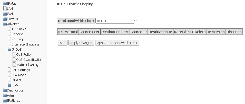
Total Bandwidth Limit (kb) — total bandwidth limit, kbit.
To add, click Add and complete the appropriate fields.
Advance → IP QoS → Traffic Shaping → Add
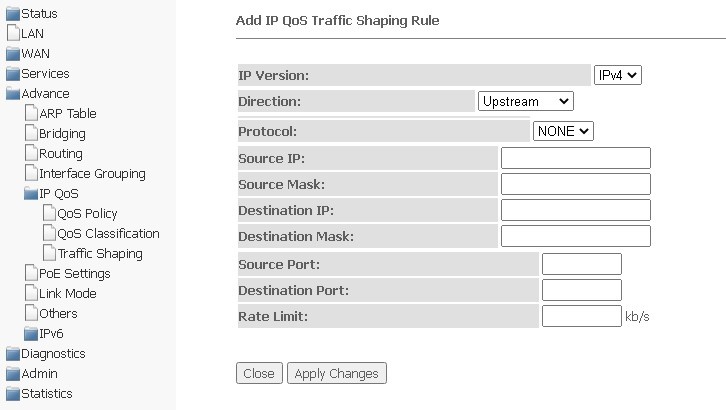
- IP Version — select the IP version;
- Direction — selection of the flow type, descending or ascending;
- Protocol — protocol;
- Source IP — source IP address;
- Source Mask/Prefix Length — mask/prefix length of the source subnet;
- Destination IP — destination IP address;
- Destination Mask/Prefix Length — mask/prefix length of the destination subnet;
- Source Port — source port;
- Destination Port — destination port;
- Rate Limit (kb/s) — speed limit, kbps.
To save the changes, click Apply Changes, to cancel, click Close.
PoE Settings submenu. Configuring PoE ports
This page is used to configure PoE settings. Here, you can enable/disable PoE on LAN ports; to do this, you need to select Enable or Disable.
Advance → PoE Settings
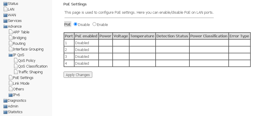
- Port — LAN port number (1-4);
- PsE enabled:
- Enabled — PoE is enabled;
- Disabled — PoE is disabled.
- Power — power consumption, W;
- Voltage — voltage, V;
- Temperature — temperature, °C;
- Detection Status — PoE port status;
- Power Classification — the power class of the connected PoE device;
- Error Type — type of error.
To save changes, click Apply Changes.
Link mode submenu. Configuring LAN ports
In this section, you can set the mode of LAN ports operation. LAN1/2/3/4 fields are used to set up the operation mode. Available modes are 10M Half Mode, 10M Full Mode, 100M Half Mode, 100M Full Mode and Auto Mode (auto detection mode).
Advance → Link mode
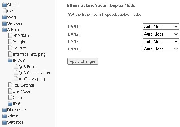
To save changes, click Apply Changes.
Others submenu. Additional settings
In this section, you can configure end-to-end IP transmission for WAN interfaces, as well as enable/disable JumboFrame transmission.
Advance → Others
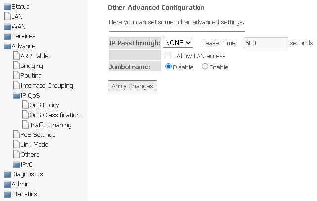
To save changes, click Apply Changes.
IPv6 submenu. Configuring IPv6 protocol
In this section, you can enable/disable IPv6; to do this, select Enable or Disable.
Advance → IPv6
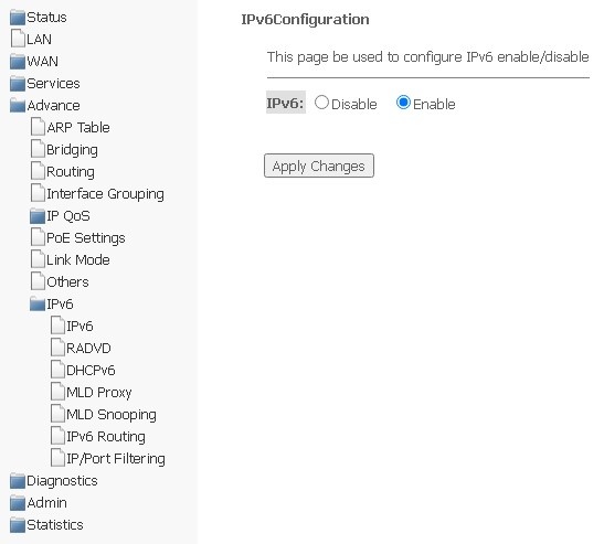
To save changes, click Apply Changes.
RADVD submenu. Configuring RADVD
The section is used to configure RADVD (Router Advertisement Daemon).
Advance → IPv6 → RADVD
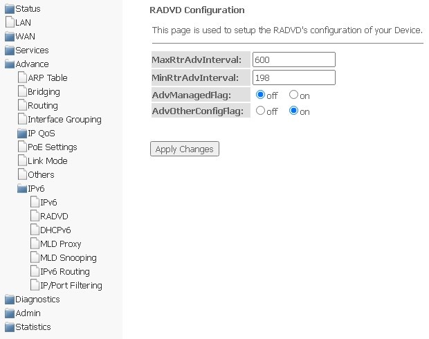
- MaxRtrAdvInterval — maximum interval for sending RA (Router Advertisement);
- MinRtrAdvInterval — minimum interval for sending RA;
- AdvManagedFlag — enable/disable sending Managed flag to RA;
- AdvOtherFlag — enable/disable sending Other RA flag.
To save changes, click Apply Changes.
DHCPv6 submenu. Configuring DHCPv6 Server
The section is used to configure DHCPv6 server. By default, it works in auto-configuration mode (DHCPServer(Auto)) via prefix delegation.
Advance → IPv6 → DHCPv6
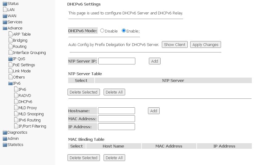
- DHCPv6 Mode — enable/disable the operation of DHCPv6 server;
- NTP Server IP — specify the IP address of NTP server for time synchronization;
- Hostname — specify the hostname;
- MAC Address — specify client's MAC address to bind the IP address;
- IP Address — specify client's IP address to bind to the MAC address.
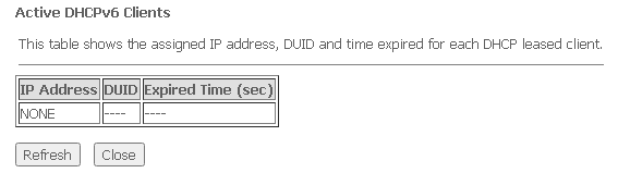
To save changes, click Apply Changes. Show Client button is used to view a table of active IP addresses of DHCPv6 server.
Advance → IPv6 → DHCPv6 → Show Client
MLD proxy submenu. Configuring MLD proxy function
In this section, you can enable/disable the operation of the MLD-proxy; to do this, you need to select Enable or Disable.
Advance → IPv6 → MLD proxy
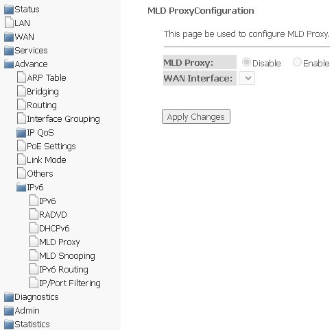
To save changes, click Apply Changes.
MLD snooping submenu. Setting up the MLD snooping function
In this section, you can enable/disable MLD-snooping; to do this, you need to select Enable or Disable.
Advance → IPv6 → MLD snooping
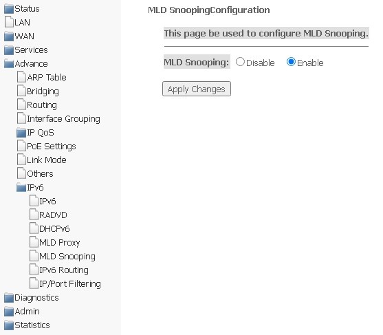
To save changes, click Apply Changes.
IPv6 routing submenu. Configuring IPv6 routes
Static IPv6 routes are configured in this section.
Advance → IPv6 → IPv6 routing
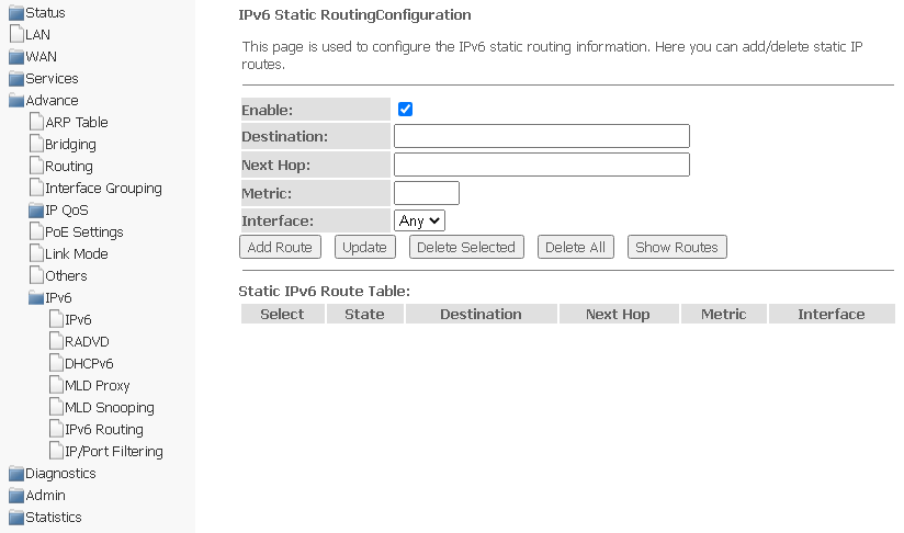
- Enable — add a route;
- Destination — destination address;
- Next Hop — next node;
- Metric — metric;
- Interface — interface.
To add IPv6 routing, complete the appropriate fields and click Add Route. The added routes are displayed in Static IPv6 Route Table, to update the information, click Update. To delete the entire table, click Delete All, to delete one route, select it and click Delete Selected. The Show Routes button displays a table of static IPv6 routes that the network usually accesses.
Advance → IPv6 → IPv6 routing → Show Routes
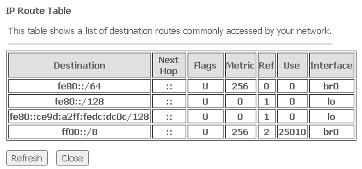
- Destination — network destination;
- Next Hop — next node;
- Flags — flags;
- Metric — metric;
- Ref — route source;
- Use — route usage;
- Interface — the interface through which the specified route is accessible.
To update the table, click Refresh, to close the window — Close.
IPv6 IP/Port filtering submenu. Configuring packet filtering
The page is used to configure filtering of data packets transmitted through the gateway.
Advance → IPv6 → IP/Port filtering
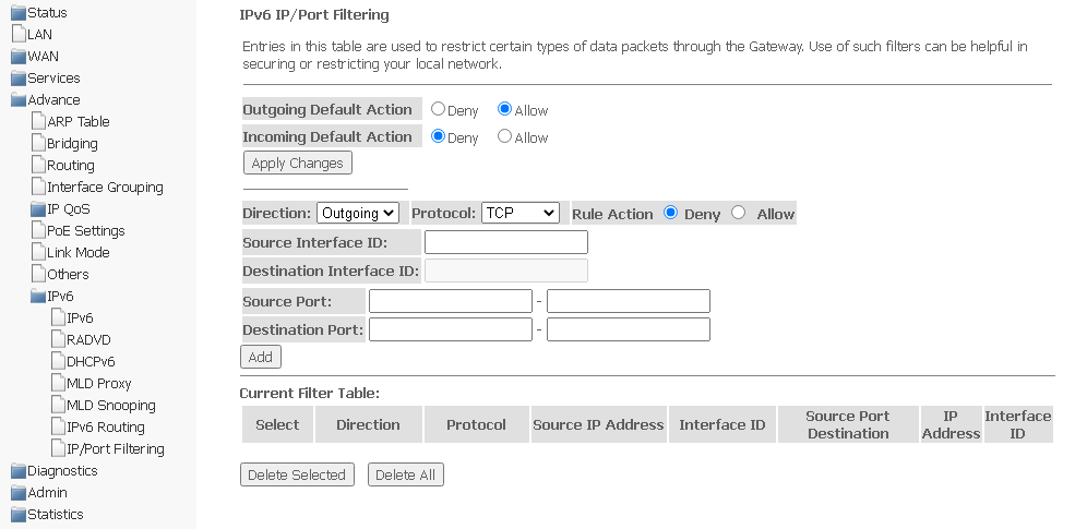
- Outgoing Default Action Deny/Allow — filtering of outgoing packets;
- Incoming Default Action Deny/Allow — filtering of incoming packets.
To save changes, click Apply Changes.
- Direction — direction of packet transmission (outgoing/incoming);
- Protocol — select protocol;
- Rule Action — packet processing policy (Deny — drop out; Allow — transmit);
- Source Interface ID — source interface;
- Destination Interface ID — destination interface;
- Source Port;
- Destination Port.
To add a filter, complete the appropriate fields and click Add. The added filters are displayed in Current Filter Table. To delete the entire table, click the Delete All button; to delete one filter, select it and click Delete Selected.
Diagnostics menu
The section is for diagnostics of access to various network nodes.
Ping submenu. Checking the availability of network devices
The section is designed to check the availability of network devices using the Ping utility.
Diagnostics → Ping
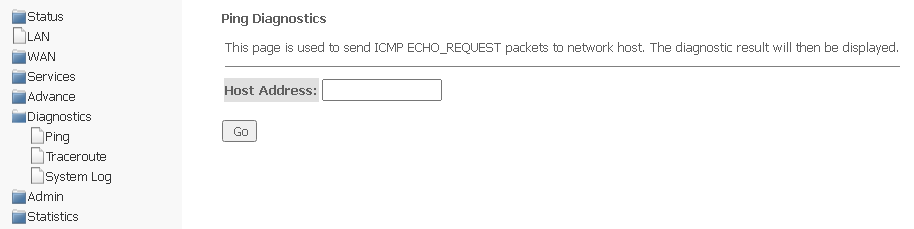
To check the availability of the connected device, enter its IP address in the Host Address field and click Go.
Traceroute submenu. Network diagnostics
The section is intended for network diagnostics by sending UDP packets and receiving a message about port availability/unavailability.
Diagnostics → Traceroute
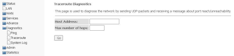
To diagnose a network, you should enter an IP address of the connected device in the Host address field and the maximum number of hops for a packet.
System Log submenu. Logging system events
The section is intended for configuring/saving/viewing logging of system events. Logging can be disabled/enabled by selected Disable or Enable.
Diagnostics → System Log
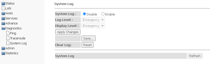
- Log Level — logging level;
- Display Level — log display level;
- Clear log — clear the log.
To save the log to the local storage, click the Save button.
Admin menu
Device management section. In this menu, passwords, time, configurations and other settings are configured.
Settings submenu. Restore and reset settings
Admin → Settings → Backup Settings

In the section, you can copy the current settings to a file (Backup Settings) by clicking Backup Settings to File.
Admin → Settings → Update Settings
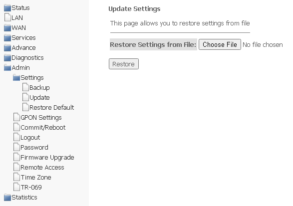
In the section, you can restore settings from a file that was saved earlier (update settings). Click Choose File to select a file, then click Restore.
Admin → Settings → Restore Default
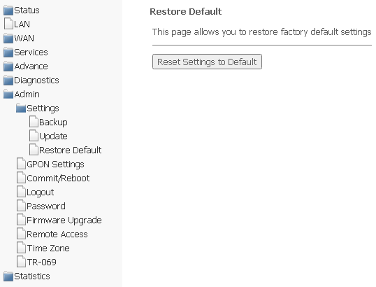
In this section, you can reset the current settings to the factory default settings (Restore Default), to do this, click Reset Settings to Default.
GPON Setting submenu. Configuring access to GPON
In this section, you can specify a password to activate the device on OLT.
Admin → GPON Setting
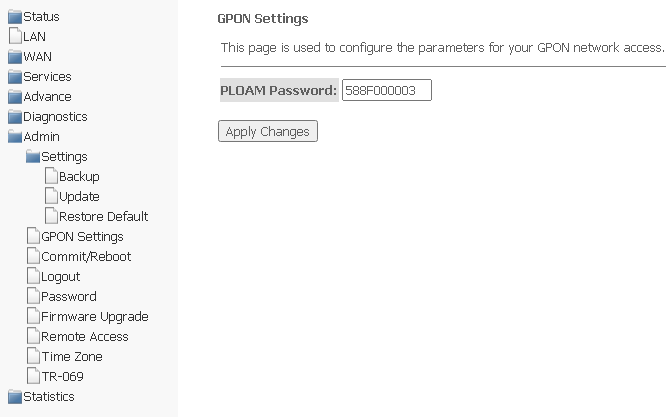
- PLOAM Password — password to activate the terminal on OLT.
To save the changes, click Apply Changes.
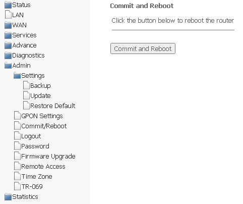
Commit/Reboot submenu. Saving changes and restarting the device
Click Commit and Reboot to reboot the device or to save changes to the system memory. It may take several minutes to restart the device.
Admin → Commit/Reboot
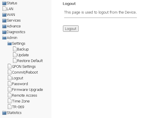
Logout submenu. Log out the account
In the section it is possible to log out the account by clicking Logout.
Admin → Logout
Password submenu. Setting up access control (setting passwords)
In this section, you may change the password for access to the device.
Admin → Password
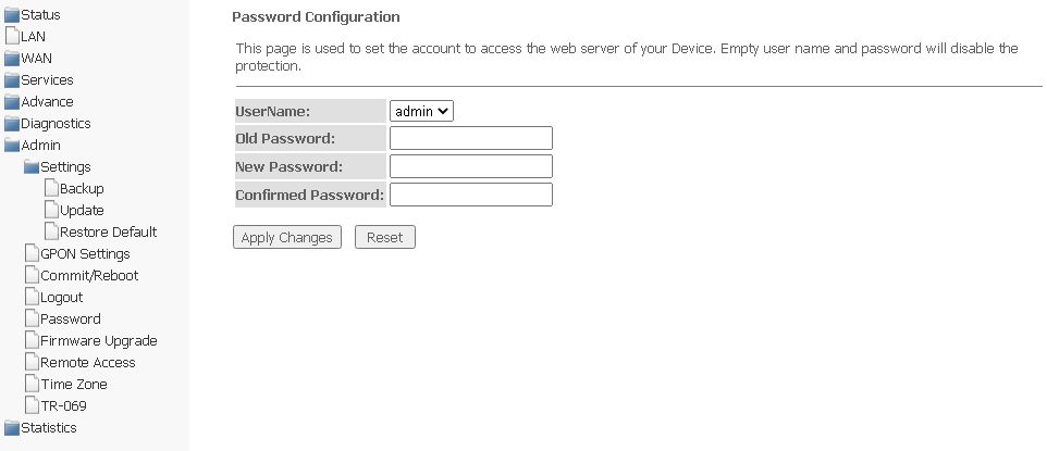
To change the password, enter the current password to the Old Password field, then the new password to New Password and to Confirmed Password.
To save changes, click Apply Changes; to reset the value, click Reset.
Firmware upgrade submenu. Software Update
To update the software, select the software file using the Choose File button and click Upgrade. To reset the value, use Reset.
Admin → Firmware upgrade
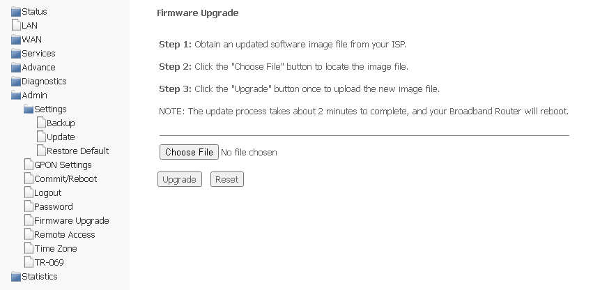
During the update process, it is not allowed to turn off the device's power or restart it. The update process may take several minutes, after which the device automatically reboots.
Remote Access submenu. Configuring remote access rules
In the section it is possible to configure remote access rules using HTTP/Telnet/ICMP protocols.
Admin → Remote Access
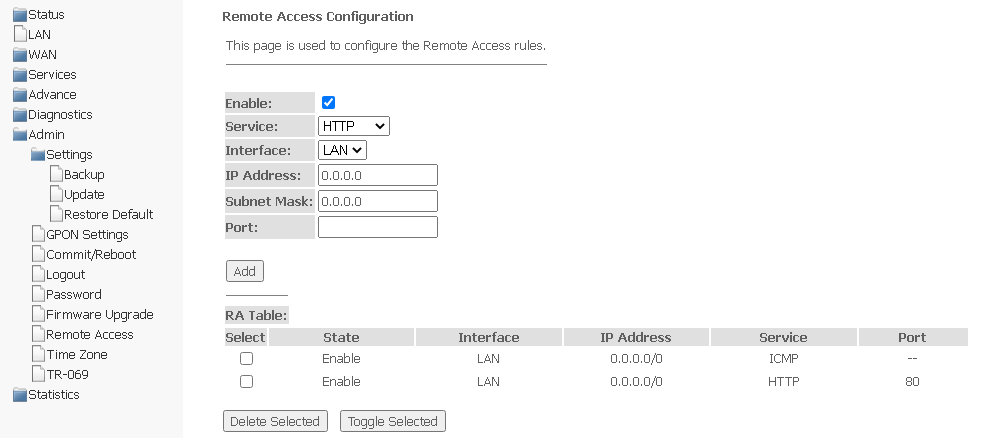
- Enable — add a rule;
- Service — select protocol;
- Interface — an interface to which the rule applies;
- IP Address — source IP address;
- Subnet Mask — subnet mask;
- Port — destination port.
To add a rule, complete the appropriate fields and click Add. The added rules are displayed in RA Table. To activate/deactivate the selected rule, click the Toggle selected button. To delete one rule, select it in the column Select and click Delete Selected.
Time zone submenu. Configuring system time
In this section you may configure system time, synchronization with Internet servers of the exact time is also available.
Admin → Time zone
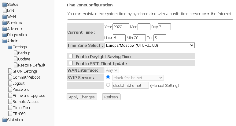
- Current time — current time;
- Time Zone Select — time zone;
- Enable Daylight Saving Time — daylight saving time;
- Enable SNTP Client Update — enable SNTP time synchronization;
- WAN Interface — the interface through which the time is updated;
- SNTP Server is the preferred time server.
To save changes, click the "Apply Changes" button, and to update the information, click the "Refresh" button.
TR-069 submenu. Configuring TR-069
The section is used to specify the data for configuring the device via TR-069.
Admin → TR-069
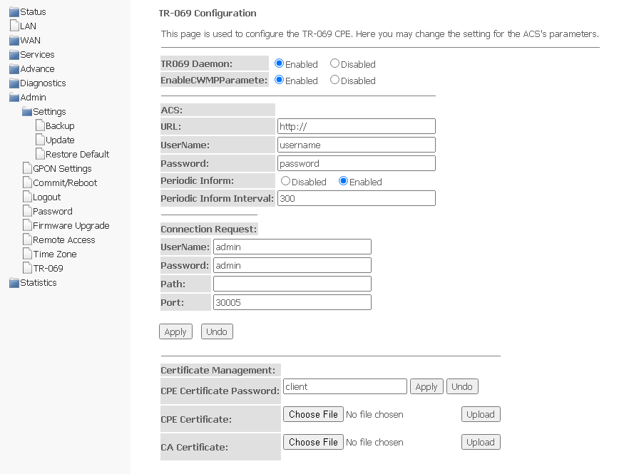
- TR069 Daemon — enable/disable TR-069 daemon;
- EnableCWMPParamete (Enabled/Disabled) — permission/prohibition of CWMP settings;
- ACS — configuring the ACS server;
- URL — URL for connection;
- UserName — the name of the user to access the server;
- Password — the user's password to access the server;
- Periodic Inform — enabling/disabling the frequency of sending messages;
- Periodic Inform Interval — the time interval of sending messages.
Connection Request — authorization data for connecting the server to ONT.
- UserName — user name;
- Password — password for connection;
- Path — connection path;
- Port — port to connect to.
Certificate Management — certificate management.
- CPE Certificate Password — certificate password;
- CPE Certificate — select certificate for CPE;
- CA Certificate — select certificate for CA.
To save changes, click Apply, to reset — Undo.
To upload a file, click Choose File to select a file, then click Upload.
Statistics menu. Information about the traffic on the device ports
Interface submenu. Information about counters and errors
The section displays counters/errors in packets for each interface:
Statistics → Interface
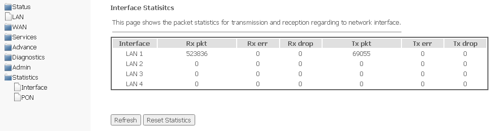
- Interface — interface;
- Rx pkt — received packets;
- RX err — reception errors;
- Rx drop — dropped on reception;
- Tx pkt — packets sent;
- Tx err — sending error;
- Tx drop — dropped during transmission.
To update the data on the page, click Refresh.
PON submenu
The section displays counters for the optical interface:
Statistics → PON

The following statistics are available:
- Bytes Sent;
- Bytes Received;
- Packets Sent;
- Packets Received;
- Unicast Packet Sent;
- Unicast Packet Received;
- Multicast Packets Sent;
- Multicast Packets Received;
- Broadcast Packet Sent;
- Broadcast Packet Received;
- FEC Errors;
- HEC Errors;
- Packets Dropped;
- Pause Packets Sent;
- Pause Packets Received.