For configuration, use an already added controller or add a new one (see Connecting the IPA-ER controller section).
It is necessary to connect the controller according to the Turnstile scheme from the section Controller connection schemes and create location.
Relay configuration
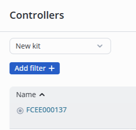
Enter the Controllers page in the Devices section in the web interface.
Click on the name of the controller FCEE000137.
Swith to the Relay tab.
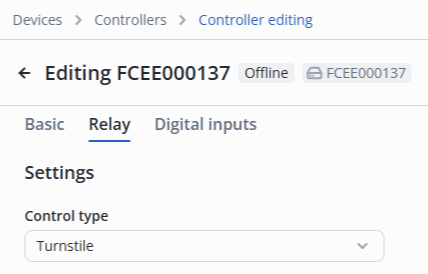
Select the Turnstile control type in the Settings section.
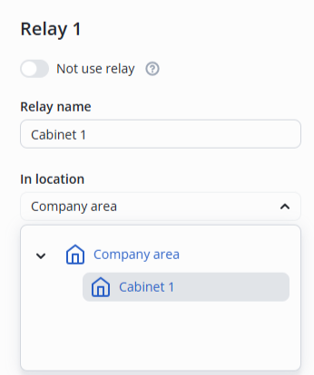
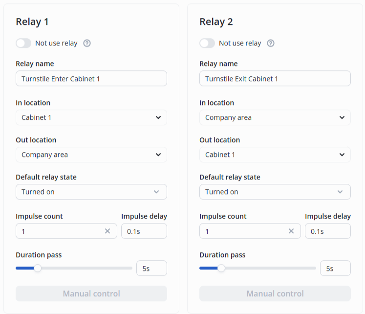
Relay 1
Specify the name of the relay — Turnstile Enter Cabinet 1.
For Relay 1, select the following:
- In location: Cabinet 1;
- Out location: Company area.
Relay 2
Specify the name of the relay — Turnstile Exit Cabinet 1.
For Relay 2, select the following:
- In location: Company area;
- Out location: Cabinet 1.
The final configuration looks as follows:
Digital inputs configuration
Switch to the Digital inputs tab.
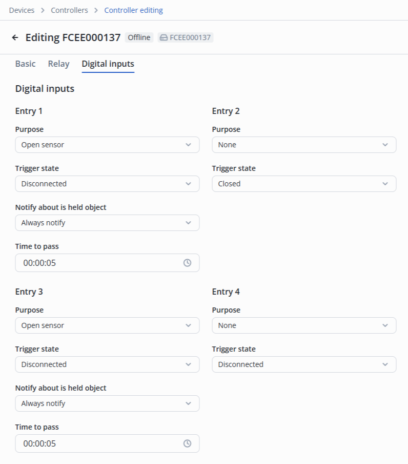
Configure as described below:
- Entry 1 — Open sensor, Trigger state — Disconnected. Notification of object being held — Always notify (by default). Time to pass — 00:00:05 (by default);
- Entry 2 — None;
- Entry 3 — Open sensor, Trigger state — Disconnected. Notification of object being held — Always notify (by default). Time to pass — 00:00:05 (by default);
- Entry 4 — None.
Click the Save button in the lower right corner.
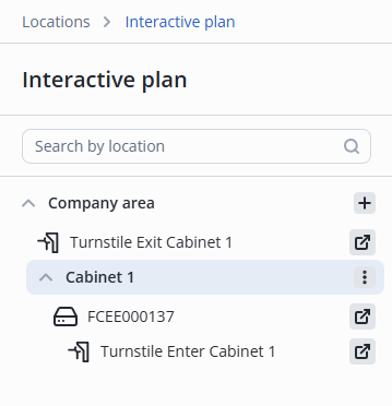
After that, on the Interactive plan page Relay 1 will display with the name Turnstile Entrance Cabinet 1, which controls the turnstile.
Beforehand, open the folder using the ![]() button next to its name.
button next to its name.
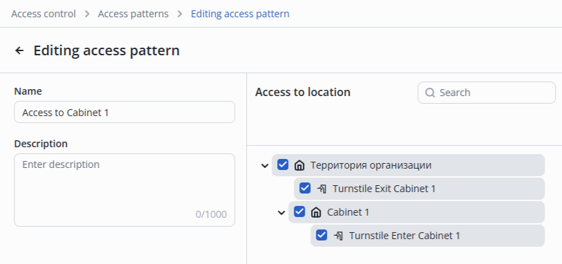
Then it is necessary to add both relays of the controller to the Access to Cabinet 1 access pattern .
Click the Save button in the lower right corner.
After successful addition, a notification will appear at the bottom middle of the screen to indicate that the operation was successful.
After that, it is possible to add a worker and pass through the turnstile, similar to passing through the door.