The most popular diagrams of connection of the IPA-ER PACS controller to the passage points are provided below.
Door
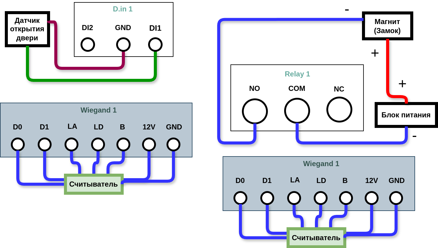
Diagram 1 — Door with 2 readers
| Object | Control type | Reader | Relay | Sensors | Magnet | Additional devices |
|---|---|---|---|---|---|---|
| Door | One door | 2 | 1 | Open sensor — 1 | 1 | - |
In this diagram, the plus is connected directly to the magnet and the minus is connected through the relay.
The door opening sensor must be connected to D.in1 to register worker passages (in the Access log in the EVI Platform).
- Digital input 1 — Sensor, Trigger state — Disconnected;
- Digital input 2 — None;
- Digital input 3 — None;
- Digital input 4 — None.
Diagram 2 — Door with 1 reader and 1 button
| Object | Control type | Reader | Relay | Sensors | Magnet | Additional devices |
|---|---|---|---|---|---|---|
| Door | One door | 1 | 1 | Open sensor — 1 | 1 | Button — 1 |
In this diagram, only one side of the IPA-ER device is used.

It is necessary to configure the Digital Inputs in the Controller settings in the EVI web interface:
- Digital input 1 — Sensor Trigger state — Disconnected;
- Digital input 2 — Button Trigger state — Closed;
- Digital input 3 — None;
- Digital input 4 — None.
Turnstile diagrams
Diagram 3 — Turnstile
| Object | Control type | Reader | Relay | Sensors | Magnet | Additional devices |
|---|---|---|---|---|---|---|
| Turnstile | Turnstile | 2 | 2 | - | - | - |
To connect the turnstile, the following diagram is used.

It is necessary to configure the Digital Inputs in the Controller settings in the EVI web interface:
- Digital input 1 — Open sensor Trigger state — Disconnected;
- Digital input 2 — None;
- Digital input 3 — Open sensor Trigger state — Disconnected;
- Digital input 4 — None.